Abstract
The intrinsic high electrical resistivity of diamond-like carbon (DLC) films prevents their use in certain applications. The addition of metal or nitrogen during the preparation of the DLC films leads to a lower resistivity of the films, but it is usually accompanied by several disadvantages, such as a potential contamination risk for surfaces in contact with the film, a limited area that can be coated, deteriorated mechanical properties or low deposition rates of the films. To avoid these problems, DLC films have been prepared by plasma source ion implantation using aniline as a precursor gas, either in pure form or mixed with acetylene. The nitrogen from the precursor aniline is incorporated into the DLC films, leading to a reduced electrical resistivity. Film properties such as hardness, surface roughness and friction coefficient are nearly unchanged as compared to an additionally prepared reference sample, which was deposited using only pure acetylene as precursor gas.
1. Introduction
Diamond-like carbon (DLC) films offer many advantageous properties, such as biocompatibility, a high hardness, a low wear rate and a low friction coefficient [1,2,3]. Their electrical resistivity spans a wide range, from 1 to 1014 Ω m [3], with the value depending markedly on the preparation method of the films. Several methods are suitable for the deposition of DLC films, such as ion beam deposition, sputtering, cathodic arc, pulsed laser deposition (PLD), and plasma-enhanced chemical vapor deposition (PECVD) [2]. Nevertheless, it is usually difficult to achieve a low electrical resistivity. In some applications, however, the DLC should be conductive at least to some extent. When coating a transport jig, which is used for semiconductor wafers, with a DLC film, it is essential that no electrostatic charges are present on the jig’s surface since otherwise it will attract dust particles. Furthermore, a three-dimensional sample such as a transport jig has to be coated on all sides. Having a large diameter, however, it is not easy to rotate a transport jig in front of a small, directional coating device such as a magnetron source. Therefore, plasma source ion implantation (PSII) is the method of choice for coating samples like this. PSII works well on three-dimensional samples because it attracts ions from a plasma by a high voltage connected to the sample [4]. Apart from the feasibility of conformal coating, other advantages of PSII include a high ion current density, low deposition temperature, easy scale-up for the treatment of large areas and relatively short processing times. Disadvantages are the lack of mass separation of the ions, a non mono-energetic implant energy, and a limited treatment of insulating samples [4,5].
To prepare conductive DLC films, usually metals [6] or nitrogen [7] are incorporated into a DLC film. However, this also introduces several disadvantages. Metal-containing DLC films possess a higher surface roughness [8,9] and in most cases a higher friction coefficient [6]. Depending on the type of metal and its amount, the hardness of the films might be lower [8,10]. If semiconductors are in contact with the surface of a metal-containing DLC film, they might be contaminated by the release of metal atoms from the film. Even trace impurities of metals affect the overall device quality of semiconductors [11]. Furthermore, most deposition methods for metals are directional, and thus they limit the ability to coat three-dimensional samples homogeneously.
Using nitrogen instead of a metal, most of the problems mentioned above can be avoided. Typically, nitrogen is added to the preparation process in the form of nitrogen gas (N2) facilitating the homogeneous coating of three-dimensional samples with nitrogen-containing DLC (N-DLC) films by PSII. However, the deposition rate is considerably lower when N2 is present as precursor because of the sputtering that occurs when nitrogen ions hit the sample surface [10,12]. The addition of nitrogen to DLC films lowers their hardness [7,10,13].
There have been reports on the deposition of conductive DLC films by using a PSII process with a bipolar pulse, with [14] and without [15] the addition of nitrogen. The positive pulse leads to a bombardment of the sample by electrons. Combined with a large negative pulse, which was found to be more effective in reducing the resistivity of the samples [16], this heats the sample to a temperature of about 400 °C. This temperature is not suitable for all substrates and, in fact, negates one of the main advantages of PSII, namely its low deposition temperature.
Rarely, other gases that can act simultaneously as a carbon source and as a nitrogen source have been used. Examples are pyridine (C6H5N) [17], which required high substrate temperatures to be effective in reducing the electrical resistivity, and pyrrole (C4H5N) [18], which produced films with an electrical resistivity not lower than 550 Ω m. Here, we investigated the feasibility of the use of a novel precursor, aniline (C6H7N). Aniline offers several advantages: it is liquid at room temperature and easy to evaporate. It possesses carbon–nitrogen bonds, yet is safer and easier to handle than some other organic molecules that contain nitrogen. Based on results regarding the use as precursors of aromatic hydrocarbons, i.e., benzene and toluene, a high deposition rate can be expected [19,20], together with a high hardness [21]. To investigate the influence of the aniline on the film properties, three different types of samples were prepared: using only aniline, only acetylene (C2H2) and mixing aniline and acetylene in different flow ratios.
2. Materials and Methods
The DLC films were prepared in a homemade PSII system as shown in Figure 1. The gases were introduced via separate feed lines and regulated to a pressure of 1.6 Pa. The acetylene line was equipped with a mass flow controller (MFC), whereas the aniline line had a leak valve with manual control. By changing the flow rates of aniline and acetylene, the composition of the films was varied, i.e., a higher acetylene flow rate corresponds to a lower aniline flow rate. In the results section, only the acetylene flow rate will be reported since only this flow rate could be metered easily. The samples were placed on a conductive sample holder that was connected to a high voltage pulse generator. A pulse of −18 kV was used. A higher voltage leads to a higher deposition rate, a better film adhesion and lower residual stress within the film [22]. To comply with the limitation of the duty cycle of the pulser of 1%, a pulse length of 100 µs and a repetition rate of 100 Hz was used. The deposition time ranged from 85 to 152 min. The varying times were selected to compensate, at least partially, for different deposition rates with changing precursor composition.
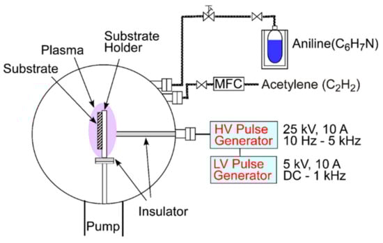
Figure 1.
Schematic of the plasma source ion implantation (PSII) system used for the deposition.
The film thickness was determined by profilometer measurements scanning over the border of coated and non-coated parts of the sample. The latter originated from the holding mechanism. The composition of the samples and the bonding was evaluated by X-ray photoelectron spectroscopy (XPS, Kratos AXIS Ultra, Shimadzu Corporation, Kyoto, Japan). The values are from a depth near the surface, i.e., after sputtering for 10 s with a 2 keV Ar ion beam. Depth profiles were recorded by secondary ion mass spectrometry (SIMS, ims 5f, CAMECA, Courbevoie, France) using Cs as primary ions with 5.5 keV energy. Positive Cs clusters of the type CsX+ were detected. The relative hydrogen content of the samples was estimated by comparing the hydrogen and carbon intensities with those of a standard sample with 19 at % hydrogen (value from elastic recoil detection analysis, ERDA, HRBS-1000, Kobe Steel Ltd., Tokyo, Japan). The carbon bonding was investigated by Raman spectroscopy (WITec alpha 300R, WITec, Ulm, Germany) using a laser with 532 nm wavelength and a power of 1 mW. After a linear background correction of the spectra, peaks were fitted with Gaussian functions. The hardness of the films was measured via nanoindentation (Hysitron, Minneapolis, MN, USA). Area scans of 1 × 1 µm2 yielded the average surface roughness Ra of the films (Nanoscope III, Digital Instruments, Santa Barbara, CA, USA). A tribometer with a ball-on-disk setup (Standard Tribometer, CSEM Instruments, Peseux, Switzerland) was used to record the friction coefficient of the films during a test with a tungsten carbide ball, a force of 2 N and a rotation speed of 100 mm/s. The electrical resistivity of the films was measured with a four-point probe station (1 mm probe spacing; 3458A, Agilent Technologies Japan Ltd., Tokyo, Japan).
3. Results
The thickness of the films varied between 111 and 322 nm. The deposition rate for a process with pure aniline gas was about 150 nm/h. This value decreased with increasing acetylene flow, as depicted in Figure 2. With an acetylene flow of 6 sccm, the deposition rate is only about 60 nm/h.
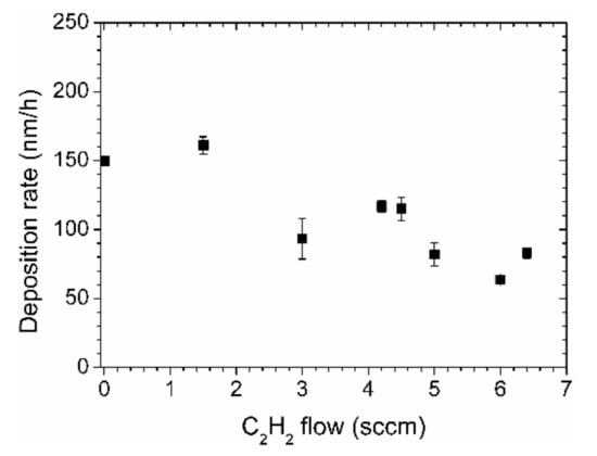
Figure 2.
Deposition rates of nitrogen-containing diamond-like carbon (N-DLC) films prepared by aniline and acetylene.
Even though the ratio of nitrogen to carbon in aniline is 1:6, the nitrogen content in the N-DLC films deposited by aniline is only about 3.5 at % as determined by XPS, Figure 3. The N concentration decreases linearly with the acetylene flow, down to about 1.5 at %. Those values represent the concentration near the surface of the samples, after a short cleaning step by ion bombardment to remove surface contaminations.
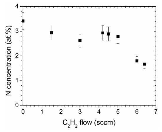
Figure 3.
Nitrogen concentrations of the N-DLC films as determined by X-ray photoelectron spectroscopy (XPS).
That the elemental distribution with depth is reasonably constant can be seen in the depth profile, Figure 4. The intensities of the matrix elements, C, H, and N run parallel. Oxygen possesses only small intensities except for the interface where a larger content is present, probably due to the natural oxide layer of the silicon wafer. When interpreting the data, it should be remembered that absolute intensities in SIMS measurements cannot be directly converted to concentrations. However, changes in relative intensity ratios of cesium clusters give a fairly accurate picture of the changes in relative concentrations [23]. Taking the average values of CsN+/CsC+ for most of the depth profile (neglecting the surface and the interface region), and plotting them in Figure 5 versus the nitrogen concentrations as determined by XPS, a near linear relationship can be derived. Therefore, the nitrogen concentrations as depicted in Figure 3 are representative of the entire layer.
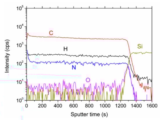
Figure 4.
Secondary ion mass spectrometry (SIMS) depth profile of the N-DLC film prepared with pure aniline. The displayed intensities are the ones of the CsX+ clusters.
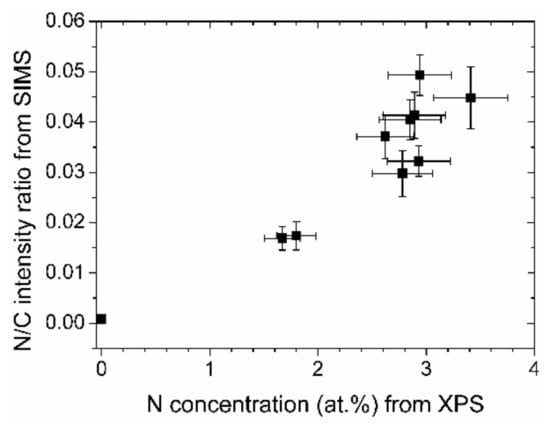
Figure 5.
Absolute and relative nitrogen concentrations of the (N-)DLC samples from XPS and SIMS measurements, respectively.
The relative hydrogen content of the samples, expressed by the CsH+/CsC+ ratio of the depth profiles is shown in Figure 6. The more nitrogen the DLC films contain, the less hydrogen is present. The absolute values of the hydrogen concentration are quite low. The intensity ratio of a standard sample with 19 at % hydrogen has a higher ratio as indicated by the line in Figure 6.
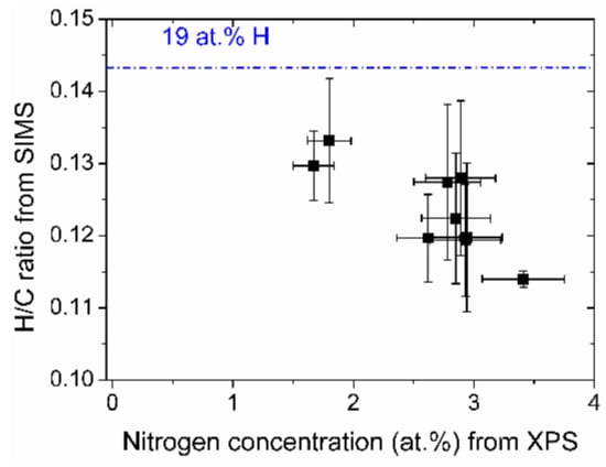
Figure 6.
Relative hydrogen content vs. nitrogen concentration of the (N-)DLC samples. The value of the hydrogen/carbon ratio of a sample containing 19 at % hydrogen is indicated by a line.
In the Raman spectra, the films show the typical broad peak of DLC films, with the D and the G peak around 1330 and 1550 cm−1, respectively, Figure 7a. The G peak corresponds to the in-plane bond-stretching motion of pairs of C sp2 atoms, whereas the D peak is characteristic of the A1g symmetry breathing mode of C in aromatic ring structures, which is only active in the presence of disorder. Even though both peaks originate from sp2 carbon, the area ratio of the peaks, ID/IG, is correlated to the sp3 content of the sample [24]. The intensity ratio ID/IG has a value of about 1.2 for a sample prepared by pure acetylene. By adding aniline, the value increases to about 1.6 for the highest nitrogen concentration, Figure 7b.
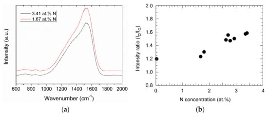
Figure 7.
(a) Raman spectra of two N-DLC samples with different nitrogen contents; (b) area ratio ID/IG of the D and the G peak from the Raman spectra vs. nitrogen concentration of the (N-)DLC samples.
In the high-resolution XPS spectra in Figure 8, recorded after the Ar ion sputtering mentioned above, the C1s peak shows sp2 and sp3 bonding at 284 and 284.8 eV, respectively. The ratio sp2/sp3 as evaluated from the peak areas is about 1.4. There are smaller contributions of C=N (285.3 eV) and C–N bonding (288.2 eV), too. In the N1s spectrum, two differently coordinated nitrogen bonds are visible, a two-coordinated one around 398 eV and a three-coordinated one around 400 eV.
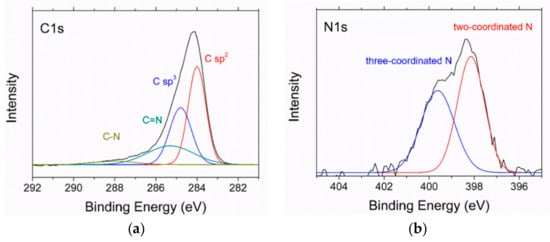
Figure 8.
XPS spectra of the N-DLC sample with 2.8 at % nitrogen: (a) C1s spectrum; (b) N1s spectrum.
The hardness of the samples changes only little by changing the acetylene/aniline flow ratio of the process gas. All the values of the hardness are between 10.9 and 12.4 GPa, Table 1. The comparison value of a DLC film prepared by pure aniline is 12.3 GPa. The values of the average surface roughness Ra are around 0.2 nm, Table 1. In absolute terms, the films are very smooth.

Table 1.
Hardness and average roughness Ra of the (N-)DLC samples prepared with different C2H2 flow.
Consequently, the friction coefficient is in a similar range as the one of a film prepared by pure acetylene, i.e., around 0.1. After an initial phase of values around 0.15 within the first 2000 rotations in Figure 9, the friction coefficient settles at a value of about 0.05 in the second half of the experiment.
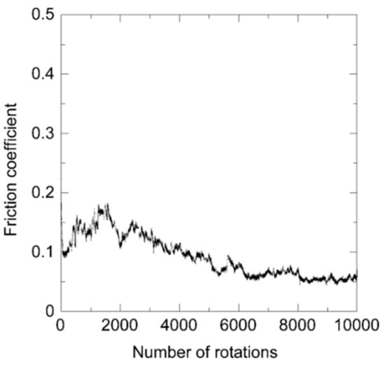
Figure 9.
Friction coefficient of an N-DLC sample prepared by pure aniline during the ball-on-disk test.
In Figure 10, the electrical resistivity of the films is depicted. All the films that were prepared with aniline possess a low resistivity, with the lowest value of 0.12 Ω m. This is more than a factor of 13 lower than the already low value of a film prepared by pure acetylene.
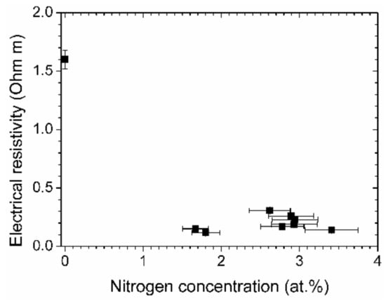
Figure 10.
Electrical resistivity vs. nitrogen concentration of the (N-)DLC samples.
4. Discussion
The highest deposition rates could be achieved for the samples with the highest nitrogen content. One might argue that the lower deposition rates of the samples with less nitrogen are due to the influence of the acetylene, which generally leads to a lower deposition rate than aromatic hydrocarbons. This would be missing the point, however. Starting with pure acetylene and adding nitrogen in the form of N2, the deposition rate decreases considerably [12]. Adding aniline instead of N2, the deposition rate increases, however, as is evident in Figure 2. The combination of a high deposition rate with a higher nitrogen content is a feature of this process.
The nitrogen concentration in the films can be controlled by the flow of the two precursor gases. The slight variations in the otherwise linear relationships in Figure 3 and in most of the other figures could be due to a slightly unstable or drifting aniline flow since the flow was not controlled by a mass flow controller. The maximum absolute nitrogen content that was achieved was about 3.5 at %. This is lower than the nitrogen fraction in the precursor, which is about 10% higher. Possible reasons for the loss of nitrogen are the fragmentation of the molecule within the plasma and the effect of sputtering during ion bombardment. Once the original nitrogen–carbon bonds of the aniline are broken, it is difficult to form them again within the film because hydrogen attaches preferably to C and N [25]. Nevertheless, regarding nitrogen addition to the film, the deposition process with aniline is more effective than that with added N2 as a precursor gas. The latter requires a nitrogen flow that is much higher than the hydrocarbon flow to prepare N-DLC samples with a few at % nitrogen [12].
The nitrogen incorporated in the film changes the bonding. The higher ID/IG ratio in the Raman spectra is indicative of a higher sp2 content of the films [26]. Two different bonds of carbon and nitrogen can be seen in the XPS spectra. In the N1s spectrum, two peaks are visible, around 398 and 400 eV. Those peaks are usually found in measurements of CN films [27]. The former can be attributed to two-coordinated carbon atoms and the latter to three-coordinated ones, with larger shifts of the peak position with changing nitrogen content being reported [28]. The lower hydrogen content with increasing nitrogen content was noticed before for films prepared with toluene and N2 [14].
The mechanical properties of the films are largely unaffected by the addition of aniline. The higher amount of graphite should make the film softer, whereas a lower hydrogen content is typically linked to a harder film [29]. Compared to a film prepared with added N2 gas [12], the XPS spectrum shows more C=N than C–N bonds. The result of the altered bonding is a hardness of the films that remains on a similar level as the one of a film without nitrogen. The surface roughness of the films is largely unaltered with the addition of aniline. The N-DLC films have the typical low surface roughness of DLC films [30]. The roughening effect that goes along with the addition of N2 can be avoided in this case because of the reduced sputtering effect. Comparing unfragmented N2 and aniline accelerated by the same pulse voltage, the atoms in the N2 have a higher energy per atom and thus cause a larger sputtering yield.
All the factors mentioned above, i.e., bonding, hardness and surface roughness, influence the friction coefficient of the film. Since most of the factors are unaltered, the typical value of between 0.05 and 0.1 for hydrogen-containing DLC films [31] was confirmed for the aniline-based sample. The effects of the increase of the graphitic (sp2) fraction, of the lower hydrogen content and of the additional C=N and C–N bonds cancel each other out. The changes might explain the initial period with the higher friction coefficient, however. In the beginning of the tribology experiment, a transfer layer builds up on the ball. This might happen in a somewhat delayed fashion for the N-DLC film in this case.
The higher graphitic content of the aniline-based samples increases the conductivity of the film. Nitrogen contributes to the electrical conductivity as it acts as a thermally activated impurity center [32]. The lowest electrical resistivity is apparently already obtained at low nitrogen concentrations of about two percent. The usual curve of resistivity vs. nitrogen content is U-shaped, with a minimum that spans a few percent of nitrogen concentration, followed by an increase of resistivity at higher nitrogen concentrations [12,32]. The minimum for the aniline-based DLC films is found at smaller concentrations than in the quoted earlier investigations, which required nitrogen contents of about five to ten percent for the lowest electrical resistivity.
It was demonstrated that N-DLC films with low electrical resistivity can be prepared by PSII using aniline as a precursor gas. The films retained good mechanical properties, and the process did not suffer from low deposition rates. It should be possible to coat large, three-dimensional samples with N-DLC films, a task that most other deposition techniques, such as sputtering and PLD are not capable of without sample manipulation. A deposition temperature of about 100 °C or less qualifies PSII for the treatment of heat-sensitive substrate materials. Compared to a PECVD process, PSII produces a better adhesion of the film to the substrate. It has been pointed out that DLC films deposited by PSII have less porosity and, thus, a higher corrosion resistance than DLC films deposited by PECVD [33] and that the use of a pulsed voltage offers a higher optimization potential [34].
While the general feasibility of N-DLC preparation by aniline in a PSII process has been shown, the optimal deposition conditions are not known yet and constitute a future research direction. Even though not much nitrogen was required to achieve a low resistivity of the samples prepared in this investigation, it cannot be ruled out that different deposition conditions could achieve a higher nitrogen concentration than 3.5 at % and/or a lower resistivity. Since the deposition conditions do not only change the nitrogen content but also other film properties, such as the carbon bonding and hydrogen content, it might be worthwhile to vary some experimental parameters. To increase the nitrogen content within the films, a lower degree of fragmentation of the precursor in the plasma might be desirable. The pulse height could be lowered, or a DC voltage of up to a few kV could be tried out. This should also decrease sputtering effects, lower the deposition temperature and change the bonding within the film. The pressure could be changed to achieve a higher hardness of the samples [35]. However, care should be taken not to compromise one of the advantages of this process, i.e., the high deposition rate. Additionally, the shape of the curve in Figure 10 in between 0 and 1.5 at % nitrogen should be investigated. This requires the precise control of small flows of aniline and thus the replacement of the manually controlled valve used in the experimental setup. Generally, the use of other nitrogen-containing precursors, with a higher nitrogen fraction for instance, might be feasible as well.
Author Contributions
Conceptualization, R.H. and K.B.; validation, R.H., S.F. and K.B.; investigation, R.H., K.B., S.F., S.H., S.T. and Y.N.; resources, K.B., W.E. and S.T.; data curation, W.E., S.T., Y.N. and K.B.; writing—original draft preparation, R.H. and S.F.; writing—review and editing, K.B.; visualization, R.H. and S.F.; supervision, K.B. and W.E.; project administration, K.B. All authors have read and agreed to the published version of the manuscript.
Funding
This research received no external funding.
Conflicts of Interest
The authors declare no conflict of interest.
References
- Lettington, A.H. Applications of diamond-like carbon thin films. Carbon 1998, 36, 555–560. [Google Scholar] [CrossRef]
- Robertson, J. Diamond-like amorphous carbon. Mater. Sci. Eng. R Rep. 2002, 37, 129–281. [Google Scholar] [CrossRef]
- Grill, A. Diamond-like carbon: State of the art. Diam. Relat. Mater. 1999, 8, 428–434. [Google Scholar] [CrossRef]
- Anders, A. (Ed.) Handbook of Plasma Immersion Ion Implantation and Deposition; John Wiley & Sons: New York, NY, USA, 2000. [Google Scholar]
- Pelletier, J.; Anders, A. Plasma-based ion implantation and deposition: A review of physics, technology, and applications. IEEE Trans. Plasma Sci. 2005, 33, 1944–1959. [Google Scholar] [CrossRef]
- Sánchez-López, J.C.; Fernández, A. Doping and alloying effects on DLC coatings. In Tribology of Diamond-Like Carbon Films; Erdemir, A., Donnet, C., Eds.; Springer: New York, NY, USA, 2008. [Google Scholar]
- Kinoshita, H.; Hando, T.; Yoshida, M. Preparation of electrically conductive diamond-like carbon films using i-C4H10/N2 supermagnetron plasma. J. Appl. Phys. 2001, 89, 2737–2741. [Google Scholar] [CrossRef]
- Corbella, C.; Bertran, E.; Polo, M.C.; Pascual, E.; Andújar, J.L. Structural effects of nanocomposite films of amorphous carbon and metal deposited by pulsed-DC reactive magnetron sputtering. Diam. Relat. Mater. 2007, 16, 1828–1834. [Google Scholar] [CrossRef]
- Corbella, C.; Vives, M.; Pinyol, A.; Bertran, E.; Canal, C.; Polo, M.C.; Andújar, J.L. Preparation of metal (W, Mo, Nb, Ti) containing a-C:H films by reactive magnetron sputtering. Surf. Coat. Technol. 2004, 177–178, 409–414. [Google Scholar] [CrossRef]
- Baba, K.; Hatada, R. Preparation and properties of nitrogen and titanium oxide incorporated diamond-like carbon films by plasma source ion implantation. Surf. Coat. Technol. 2001, 136, 192–196. [Google Scholar] [CrossRef]
- Reinhardt, K.A.; Kern, W. (Eds.) Handbook of Silicon Wafer Cleaning Technology, 3rd ed.; Elsevier: Oxford, UK, 2018. [Google Scholar]
- Flege, S.; Hatada, R.; Hoefling, M.; Hanauer, A.; Abel, A.; Baba, K.; Ensinger, W. Modification of diamond-like carbon films by nitrogen incorporation via plasma immersion ion implantation. Nucl. Instrum. Methods Phys. Res. Sect. B Beam Interact. Mater. At. 2015, 365, 357–361. [Google Scholar] [CrossRef]
- Kimura, T.; Yanai, H.; Nakao, S.; Azuma, K. Plasma based nitrogen ion implantation to hydrogenated diamond-like carbon films. Nucl. Instrum. Methods Phys. Res. Sect. B Beam Interact. Mater. At. 2018, 433, 87–92. [Google Scholar] [CrossRef]
- Nakao, S.; Soga, T.; Sonoda, T.; Asada, T.; Kishi, N. Optical and Electrical Properties of Nitrogen-Doped Diamond-Like Carbon Films Prepared by a Bipolar-Type Plasma-Based Ion Implantation. Jpn. J. Appl. Phys. 2012, 51, 01AC04. [Google Scholar] [CrossRef]
- Nakao, S.; Kimura, T.; Suyama, T.; Azuma, K. Conductive diamond-like carbon films prepared by high power pulsed magnetron sputtering with bipolar type plasma based ion implantation system. Diam. Relat. Mater. 2017, 77, 122–130. [Google Scholar] [CrossRef]
- Miyagawa, S.; Nakao, S.; Choi, J.; Ikeyama, M.; Miyagawa, Y. Effects of target bias voltage on the electrical conductivity of DLC films deposited by PBII/D with a bipolar pulse. Nucl. Instrum. Methods Phys. Res. Sect. B Beam Interact. Mater. At. 2006, 242, 346–348. [Google Scholar] [CrossRef]
- Uchida, M.; Tanaka, H.; Kotera, K. Temperature Dependence of Conductivity of Nitrogen-Containing Diamondlike Carbon Films Deposited from Pyridine. Jpn. J. Appl. Phys. 1996, 35, 5815. [Google Scholar] [CrossRef]
- Takai, O.; Anita, V.; Saito, N. Properties of DLC thin films produced by RF PE−CVD from pyrrole monomer. Surf. Coat. Technol. 2005, 200, 1106–1109. [Google Scholar] [CrossRef]
- Ensinger, W. Correlations between process parameters and film properties of diamond-like carbon films formed by hydrocarbon plasma immersion ion implantation. Surf. Coat. Technol. 2009, 203, 2721–2726. [Google Scholar] [CrossRef]
- Kirinuki, M.; Onoi, M.; Nishikawa, K.; Oka, Y.; Azuma, K.; Fujiwara, E.; Yatsuzuka, M. Negative pulsed voltage discharge and DLC preparation in PBIID system. Thin Solid Films 2006, 506–507, 68–72. [Google Scholar] [CrossRef]
- Baba, K.; Hatada, R.; Nakao, S.; Miyagawa, S.; Miyagawa, Y. Formation of diamond like carbon films by plasma source ion implantation from CH4, C2H2 and C6H6. In Proceedings of the 1998 International Conference on Ion Implantation Technology (Cat. No.98EX144), Kyoto, Japan, 22–26 June 1998; Volume 2, pp. 1214–1217. [Google Scholar]
- Kirinuki, M.; Tomita, A.; Kusuda, M.; Oka, Y.; Murakami, A.; Yatsuzuka, M. Enhancement of Adhesive Strength of DLC Film by Plasma-Based Ion Implantation. Mater. Sci. Forum 2005, 302, 315–320. [Google Scholar] [CrossRef]
- Gao, Y. A new secondary ion mass spectrometry technique for III-V semiconductor compounds using the molecular ions CsM+. J. Appl. Phys. 1988, 64, 3760–3762. [Google Scholar] [CrossRef]
- Ferrari, A.C.; Robertson, J. Interpretation of Raman spectra of disordered and amorphous carbon. Phys. Rev. B 2000, 61, 14095–14107. [Google Scholar] [CrossRef]
- Souto, S.; Alvarez, F. The role of hydrogen in nitrogen-containing diamondlike films studied by photoelectron spectroscopy. Appl. Phys. Lett. 1997, 70, 1539–1541. [Google Scholar] [CrossRef][Green Version]
- Tai, F.C.; Lee, S.C.; Wei, C.H.; Tyan, S.L. Correlation between ID⁄IG Ratio from Visible Raman Spectra and sp2/sp Ratio from XPS Spectra of Annealed Hydrogenated DLC Film. Mater. Trans. 2006, 47, 1847–1852. [Google Scholar] [CrossRef]
- Ronning, C.; Feldermann, H.; Merk, R.; Hofsäss, H.; Reinke, P.; Thiele, J.-U. Carbon nitride deposited using energetic species: A review on XPS studies. Phys. Rev. B 1998, 58, 2207–2215. [Google Scholar] [CrossRef]
- Titantah, J.T.; Lamoen, D. Carbon and nitrogen 1s energy levels in amorphous carbon nitride systems: XPS interpretation using first-principles. Diam. Relat. Mater. 2007, 16, 581–588. [Google Scholar] [CrossRef]
- Konishi, Y.; Konishi, I.; Sakauchi, N.; Hayashi, S.; Hirakimoto, A.; Suzuki, J. Measurement of hydrogen content in diamond like carbon thin films by ERDA. Nucl. Instrum. Methods Phys. Res. Sect. B Beam Interact. Mater. At. 1996, 118, 312–317. [Google Scholar] [CrossRef]
- Peng, X.L.; Barber, Z.H.; Clyne, T.W. Surface roughness of diamond-like carbon films prepared using various techniques. Surf. Coat. Technol. 2001, 138, 23–32. [Google Scholar] [CrossRef]
- Grill, A. Review of the tribology of diamond-like carbon. Wear 1993, 168, 143–153. [Google Scholar] [CrossRef]
- Derradji, N.E.; Mahdjoubi, M.L.; Belkhir, H.; Mumumbila, N.; Angleraud, B.; Tessier, P.Y. Nitrogen effect on the electrical properties of CNx thin films deposited by reactive magnetron sputtering. Thin Solid Films 2005, 482, 258–263. [Google Scholar] [CrossRef]
- Liu, C.; Yang, D.; Qi, M.; Deng, X. Advances in DLC coatings by hybrid PSII and PECVD as a barrier to corrosion in simulated body fluid. J. Mater. Sci. 2005, 40, 5603–5608. [Google Scholar] [CrossRef]
- Thièry, F.; Vallée, C.; Arnal, Y.; Pelletier, J. PECVD and PIID processing of diamondlike carbon. Surf. Coat. Technol. 2004, 186, 146–152. [Google Scholar] [CrossRef]
- Munson, C.P.; Faehl, R.J.; Henins, I.; Nastasi, M.; Reass, W.A.; Rej, D.J.; Scheuer, J.T.; Walter, K.C.; Wood, B.P. Recent advances in plasma source ion implantation at Los Alamos National Laboratory. Surf. Coat. Technol. 1996, 84, 528–536. [Google Scholar] [CrossRef]


© 2020 by the authors. Licensee MDPI, Basel, Switzerland. This article is an open access article distributed under the terms and conditions of the Creative Commons Attribution (CC BY) license (http://creativecommons.org/licenses/by/4.0/).