Article

Preparation and Thermal Shock Resistance of Gd2O3 Doped La2Ce2O7 Thermal Barrier Coatings

1
School of Physics, Beihang University, No. 37 Xueyuan Road, Beijing 100191, China
2
BGRIMM Technology Group, No. 5 Fusheng Road, Beijing 102206, China
*
Author to whom correspondence should be addressed.
Coatings 2021, 11(10), 1186; https://doi.org/10.3390/coatings11101186
Submission received: 12 August 2021 / Revised: 22 September 2021 / Accepted: 26 September 2021 / Published: 29 September 2021
(This article belongs to the Section Plasma Coatings, Surfaces & Interfaces)

Abstract

:
As one of the promising thermal barrier coating (TBC) candidates, stoichiometric (La0.8Gd0.2)2Ce2O7 (LGC) coatings were prepared by atmospheric plasma spraying (APS), using (La0.8Gd0.2)2Ce2.5O8 as a spray powder and optimized spray parameters. It was found that spray distance and spray power both play an important role in the phase composition and microstructure of the coating. The LGC coating exhibited lower thermal conductivities than that of La2Ce2O7 (LC) coating, which is ~0.67 W/m·K at 1200 °C. Double-ceramic-layer (DCL) optimum (La0.8Gd0.2)2Ce2O7/YSZ (LGC/YSZ) thermal barrier coating was prepared and its thermal shock behavior was investigated. The LGC/YSZ DCL TBCs had better thermal shock resistance ability than that of LC/YSZ TBCs, which was around 109 cycles at 1100 °C. However, the failure mode was similar to that of LC/YSZ DCL TBCs, which was still layer-by-layer spallation in the top ceramic layer due to the sintering of the ceramic coating.

1. Introduction

Thermal barrier coatings (TBCs) are widely applied onto hot-components of turbine engines to protect the components, which have a complex multi-layered structure: a metallic bond coat for oxidation/corrosion resistance and a ceramic topcoat for thermal protection [1,2]. In recent years, new TBCs preparation technology was developed, including atmospheric plasma spraying (APS) [3], electron beam-physical vapor deposition (EB-PVD) [4], plasma spray-physical vapor deposition (PS-PVD) [5,6], suspension plasma spraying (SPS) [7], solution precursor plasma spraying (SPPS) [8], and so on. Both APS and EB-PVD technology are the most widely used to deposited TBCs. The columnar microstructure coating deposited by EB-PVD is especially suitable for highly strain-tolerant thermal barrier coatings (TBCs) [9,10]. The drawbacks of EB-PVD processes are the high investment costs and the low deposition rates. APS uses a plasma jet to melt and accelerate the spray powder and, finally, form coatings with layered structure. Due to defects, such as layered gap, unmelted particles and pores in the coating, APS TBCs exhibit lower thermal conductivity (usually 0.8~1.2 W/m·K) than that of EB-PVD coatings [11]. Owing to its high deposition rates and low investment costs, it is mainly used to deposit thick coatings.
Currently, yttria stabilized zirconia (YSZ), especially 6~8 wt.% YSZ, are widely used in gas turbines [12]. However, YSZ cannot be used long-term above 1200 °C due to phase transformations and sintering, which accompany volume change and a reduction of the strain tolerance and, finally, results in the failure of the coating [13,14]. As a consequence, to further increase the operation temperature of turbine engines, new ceramic materials were developed, such as lanthanum magnesium hexaluminates (LaMgAl11O19) [15], lanthanum zirconate (La2Zr2O7) [16], gadolinium zirconate (Gd2Zr2O7) [17], lanthanum cerium oxide (La2Ce2O7,LC) [18], and rare earth oxides doped zirconia [19], which were evaluated as TBC candidate materials. Among these materials, LC possesses lower thermal conductivity, better phase stability, and a larger thermal expansion coefficient than YSZ ceramic [20]. Moreover, LC can effectively protect calcium-magnesium-alumina-silicate (CMAS) deposits from penetration due to the formation of a dense sealing layer by the chemical reaction between the CMAS deposits and the LC coating [21]. However, the thermal expansion coefficients (TEC) of LC show a sudden drop between 200 °C~400 °C, which would lead to the formation of thermal stress during thermal cycles and, finally, result in the early failure of the coatings [22]. In recent studies, it was reported that the sudden drop of the TEC can be improved by doping with oxides (Gd2O3, Ta2O3, MgO2, and CaO2) [23,24,25]. In particular, Gd2O3 doped LC is recognized as a promising TBC candidate material. According to our previous work, (La0.8Gd0.2)2Ce2O7 (LGC) had low thermal conductivity and good phase stability, hence it was designated as the optimal thermal barrier coating material among the Gd2O3 doped LC ceramics [26]. However, there is little knowledge about the preparation and performances of the coatings. As reported, due to the difference of vapor pressures between CeO2 and La2O3 [27], there is less CeO2 content in the LC coatings compared with the LC powder. Therefore, in this paper, LGC coatings were prepared by atmospheric plasma spraying (APS). In order to obtain the optimized LGC coatings, both in terms of composition and microstructure, powder composition and spray parameters were adjusted. The thermal conductivities of LGC and LC coating were compared. The thermal shock behavior of plasma spray double-ceramic-layer (DCL) optimum (La0.8Gd0.2)2Ce2O7/YSZ (LGC/YSZ) thermal barrier coatings was investigated. For comparison, the thermal shock behavior of the La2Ce2O7/YSZ (LC/YSZ) DCL TBC was also studied.

2. Materials and Methods

2.1. Processing and Materials

As reported, the spray powder composition has important influence on the coating composition [28]. In order to prepared stoichiometric LGC coating, the spray powder composition was adjusted. Lanthanum-cerium-oxide, with different CeO2 contents, were synthesized by solid-state reaction with La2O3, CeO2, and Gd2O3 at 1400 °C for 24 h, which were (La0.8Gd0.2)2Ce2O7, (La0.8Gd0.2)2Ce2.5O8 and (La0.8Gd0.2)2Ce3O9, respectively. For plasma spraying, the powders were produced by spraying dried technology and sieved-size fractions between 10 and 100 mm were used. The spray parameters, including spray power and spray distance, were also adjusted to obtain the optimized LGC coating in terms of composition and microstructure. The spray parameters are listed in Table 1. Air plasma spray (APS) with GTV F6 (GTV Thermal spray, Beijing, China) spray equipment was used to produce all the coatings.
Free-standing coating specimens for composition characterization and thermal diffusivity measurements were prepared by removing the coating from the substrate. For the thermal shock test, the LGC/YSZ DCL TBCs were prepared. LC/YSZ DCL TBCs was also deposited for comparison. Ni-based superalloy substrates were sprayed with NiCoCrAlY, followed by deposition of the ceramic top coat. Then YSZ and LGC/LC coatings were deposited onto the bond coat to prepare the DCL TBCs, and the optimized spray parameter was selected based on Section 3.1.

2.2. Thermal Shock Test

The thermal shock test was performed by the heating-and-water-quenching method in a high temperature muffle furnace. Each thermal cycle consisted of an isothermal hold at 1100 °C for 5 min and then cooling down by water. The samples were thrown into the room temperature water, where the samples were cooled to the ambient temperature. The thermal shock tests were repeated until nearly 20% of the coating surface was destroyed. The number of cycles was recorded as the lifetime of the TBCs. To reduce the influence of random error, the thermal cycling lifetimes were the mean values of three samples.

2.3. Characterization

The surface and cross-sectional morphologies of coatings were characterized by a scanning electron microscope (SEM, HITACHI SU5000, HITACHI, Tokyo, Japan) equipped with an energy dispersive spectrometer (EDS). The phase constituents of the coatings were identified by X-ray diffraction (XRD, Rigaku D/max 2200PC, Rigaku Corporation, Tokyo, Japan) using Cu Ka radiation. The chemical composition of the free-standing LGC coatings were characterized with inductively coupled plasma-optical emission spectroscopy (ICP-OES, iCAP PRO XP, Thermo Fisher Scientific, Waltham, MA, USA).
The thermal diffusivities (α) of the coatings were measured using a laser-flash apparatus (Netzsch LFA 427, Netzsch Group, Bavaria, Germany) from 20 °C to 1200 °C, at an interval of 200 °C. Prior to thermal diffusivity measurements, the surfaces of the specimens were coated with a thin film of graphite for the thermal absorption of laser pulses. Each sample was measured three times at the selected temperatures. The specific heat capacity (Cp) was calculated from the heat capacity values of the constituent oxides based on the Neumann-Kopp rule [29]. The density ( ρ ) was measured by Archimedes’ method. The thermal conductivity (λ) was obtained using the following equation:
λ = α × ρ × Cp

3. Results and Discussion

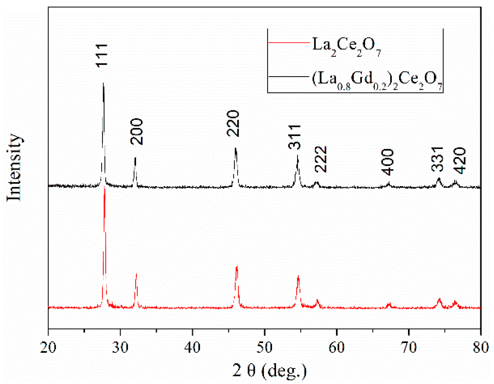
3.1. Preparation of the LGC Coating

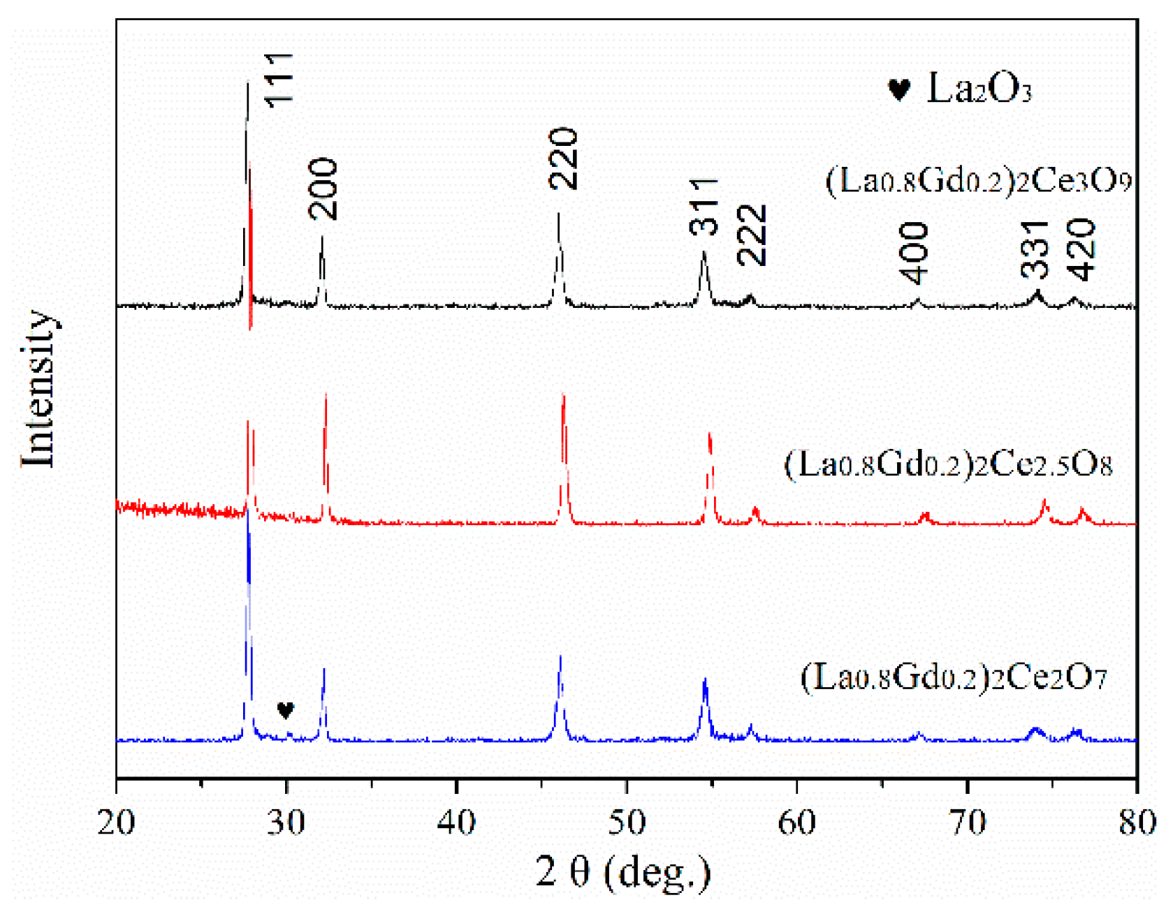
3.1.1. Effect of Spray Powder Composition

Figure 1 shows the XRD patterns of the coatings prepared by spraying different lanthanum-cerium-oxide powders. It can be observed that the coatings were mainly composed of fluorite phase. There was a small amount of La2O3 in the coating obtained by spraying (La0.8Gd0.2)2Ce2O7 powder. It was reported that the lower vapor pressure of La2O3 results in extra being left during plasma spraying when compared with that of CeO2. The lattice parameters of the coatings were calculated according to XRD patterns peaks, which were 0.5561 nm, 0.5541 nm, and 0.5577 nm when (La0.8Gd0.2)2Ce2O7, (La0.8Gd0.2)2Ce2.5O8, and (La0.8Gd0.2)2Ce3O9 were used as a spray powder, respectively.
The composition of the three above coatings were analyzed by ICP-OES. When (La0.8Gd0.2)2Ce2O7, (La0.8Gd0.2)2Ce2.5O8, and (La0.8Gd0.2)2Ce3O9 were sprayed under the same spray parameters, the (La + Gd)/Ce ratio in the as-sprayed coating was 0.78, 1.01, and 1.31, respectively. The results are listed in Figure 2, which shows the relationship of the (La + Gd)/Ce ratio between the coating and the powder. It was found that the (La + Gd)/Ce ratio in the coating increased with the increase of the (La + Gd)/Ce ratio in spray powder under the same spray parameters. When the powder of the (La + Gd)/Ce ratio was 0.8, the (La + Gd)/Ce ratio in the coating deposited was close to 1. Therefore, combined with XRD results, the feedstock powder with a nominal composition of (La0.8Gd0.2)2Ce2.5O8 can be selected to obtain the stoichiometric LGC coating.

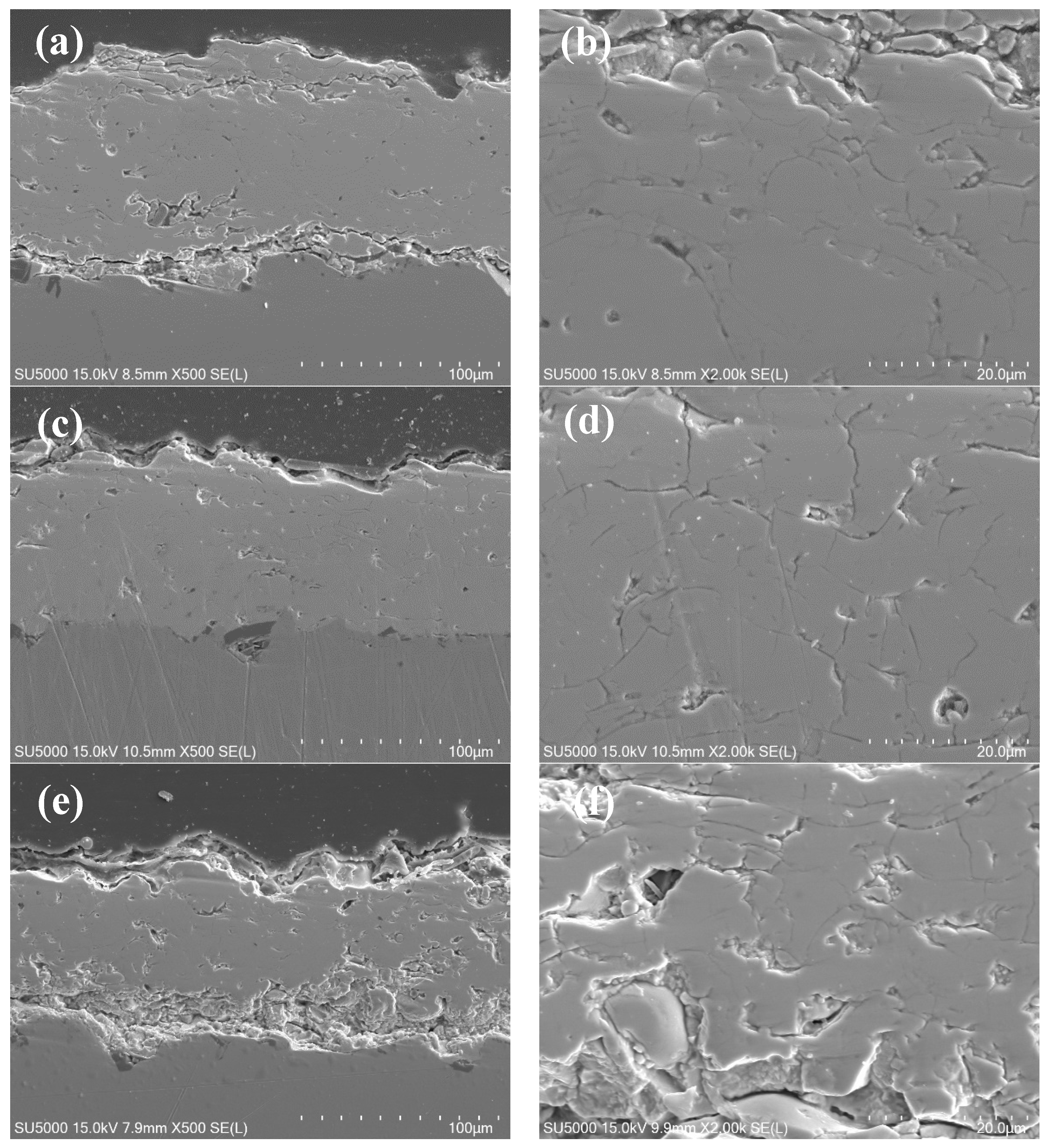
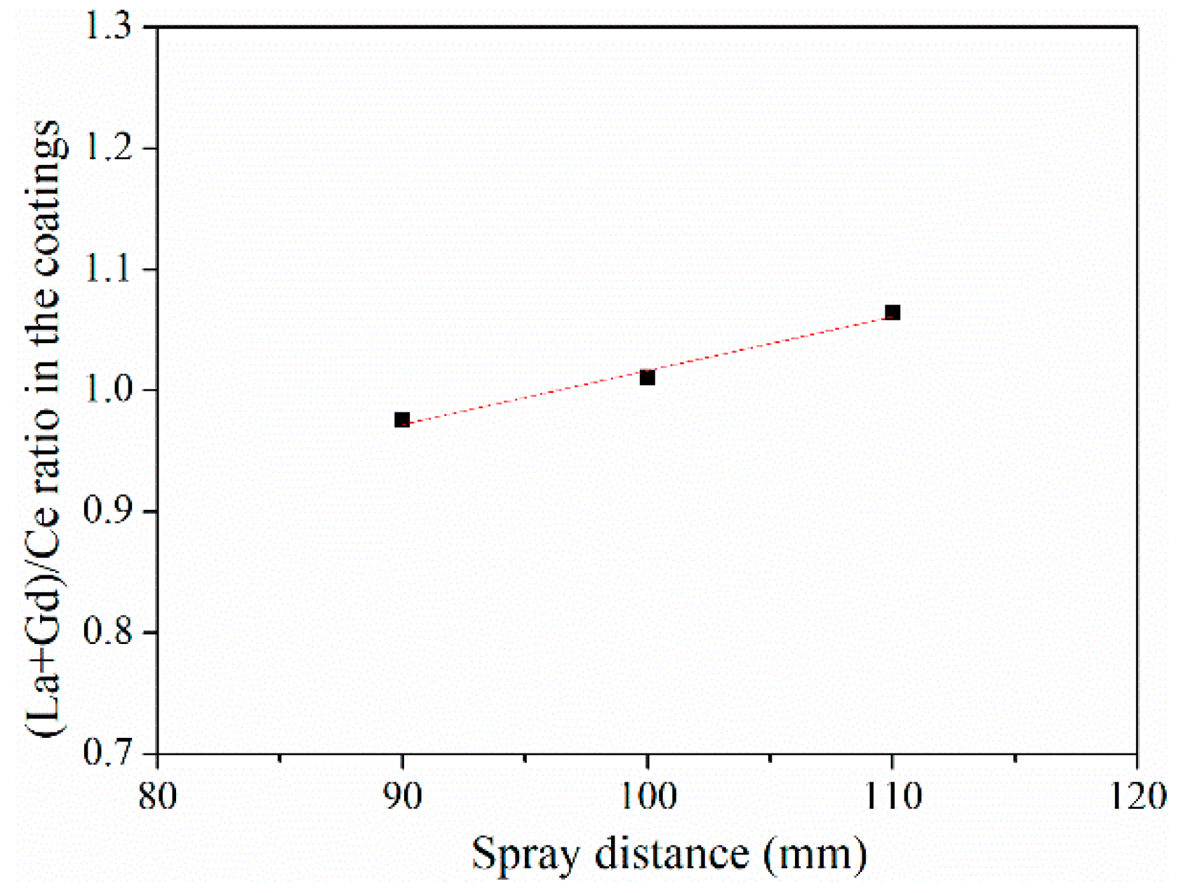
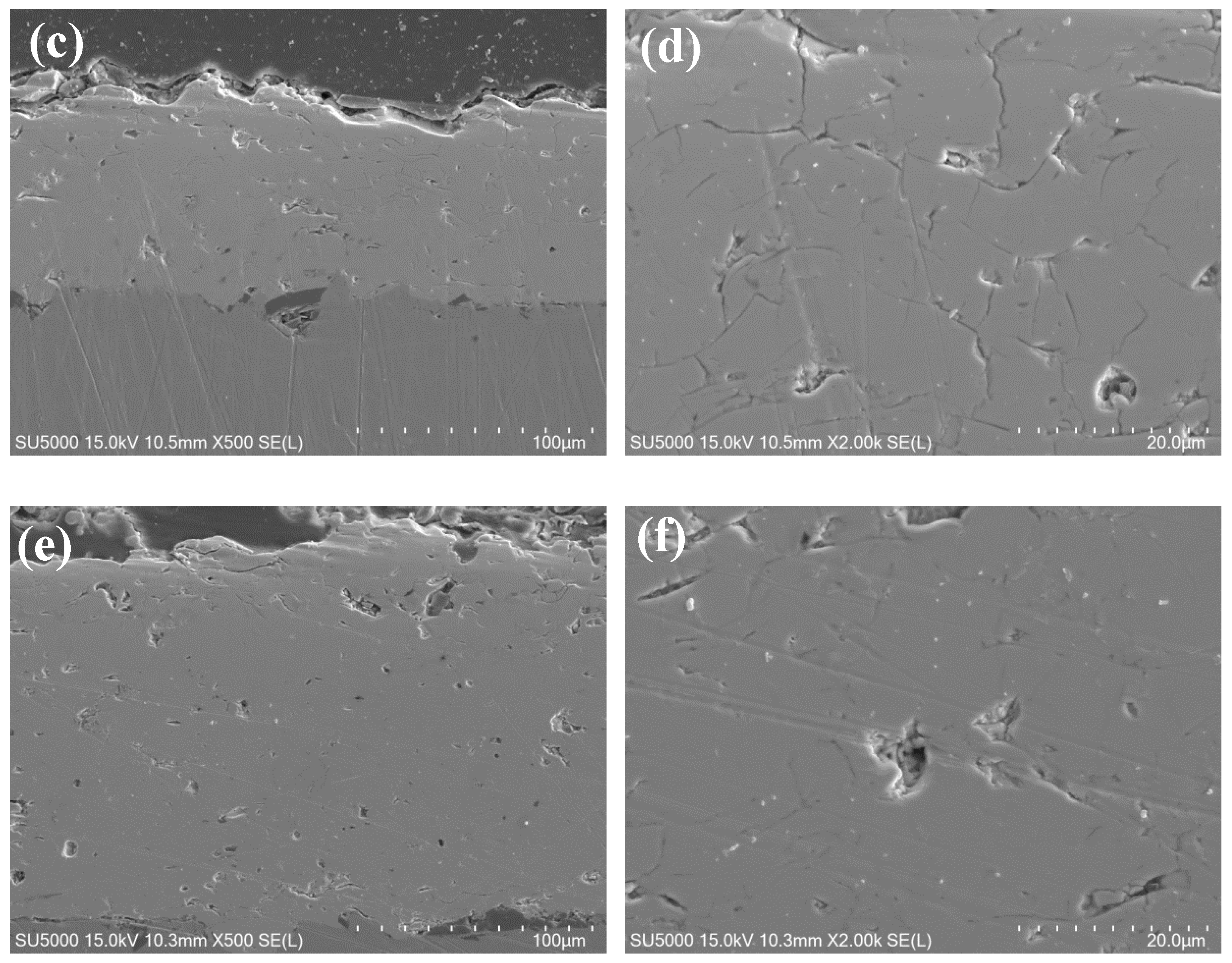
3.1.2. Effect of Spray Parameter

Figure 3 shows the cross-section morphologies of the LGC coatings prepared at different spray distances. All the coatings exhibited the typical layered structure of plasma spraying coatings. However, some obvious differences in the morphology can be observed. As shown in Figure 3a, the coating sprayed at 90 mm was dense. However, a closer examination of the coating in Figure 3b revealed that some spherical powder existed in the coating, and the size was comparable to that of the LGC feedstock, indicating that some powder was not fully melted during spraying. Some pores and defects were found around the spherical powder. It was mainly caused by insufficient contact between the unmelted powder and flattened droplets. When the spraying distance increased to 100 mm, the coating was denser and no unmelted powder was found in the coating. It can be inferred that the injected powders were almost melted. In other word, the powders were melted more fully when the spray distance increased from 90 to 100 mm. Horizontal microcracks and vertical microcracks were found in the coatings. It is widely known that during spraying, powders are heated and melted into droplets. The droplet, with high velocity, impinges on the relatively cool surface of the substrate, rapidly flattens, cools, and solidifies [30]. The rapid cooling process leads to particle volume shrinkage, but the good bonding of the splat with the sub-surface limits its contraction and, thus, thermal stress is formed within the splats. Thermal stress of brittle ceramic coating cannot be released by plastic deformation and can only be relaxed by cracking. As reported, these microcracks are helpful to improve the ability of strain relaxation and consequently lead to a longer lifetime [31].
As the spray distance continued to increase to 110 mm, the coating became porous. From its magnification morphology, it was found that the pores and defects were distributed between the layers, indicating the bonding between layers had become weak. As the spray distance increases, droplet surface temperature and speed decreases after the long-distance flight. These changes would lead to insufficient flattening and rapid cooling of droplets and, finally, result in the emergence of interlayer defects. These defects would weaken the adhesion of the coating and, finally, result in the early failure of the coatings [11].
The (La + Gd)/Ce ratio in the as-sprayed coatings as a function of the spray distance is shown in Figure 4. The (La + Gd)/Ce ratio increased with the increase of the spray distance from 90 to 110 mm, which was 0.97, 1.01, and 1.06, respectively. It can be inferred that the evaporation degree of Ce intensified with the increase of spray distance during the plasma spraying process, probably caused by the increasing heat time and melting degree of the spray powders. The ratio was close to 1 at the spray distances of 100 mm. Therefore, considering the influence of spray distance on the coating microstructure and composition, the spray distance of 100 mm was selected.
The influence of spray power on the coating microstructure and chemical composition were also discussed, as shown in Figure 5 and Figure 6, respectively. As shown in Figure 5, among the three coatings, the coating sprayed at 38 kW displayed the most pores and defects. The interlayer gaps in the coating were relatively border, indicating the weaker interlaminar adhesion. During the spraying process, the injected powder melts into droplets and when the droplets impact the substrate surface, the droplets spread and cool, finally forming a layered structure. The broader interlayer gaps may be attributed to the rapid cooling of droplet surface due to the lower jet temperature at a lower spray power. When the spray power increased, the coating become denser and the interlayer adhesion of the coating also improved. This difference was mainly caused by the different melting degree for the spray powders during spraying process, which indicates that the droplets spread out flatter and the particles are melted more fully when the plasma power increased from 38 to 46 kW. In particular, the porosity of the coating sprayed at 46 kW, determined by image analysis, was only ~8%. Low porosity, however, would lead to high thermal conductivity and low strain tolerance, and thus it is not suitable for thermal barrier coating [32,33].
Figure 6 shows the (La + Gd)/Ce ratio in the as-sprayed coatings as a function of the spray power. The (La + Gd)/Ce ratio increased with extending the spray power, which was 0.98, 1.01, and 1.04, respectively. The results indicated that the evaporation degree of Ce in the coating increased with the increase of the spray power. The ratio is close to 1 at the spray power of 42 kW. Based on the above results, a spray distance of 80 mm and a spray power of 42 kW were chosen to prepare the stoichiometric LGC coating.

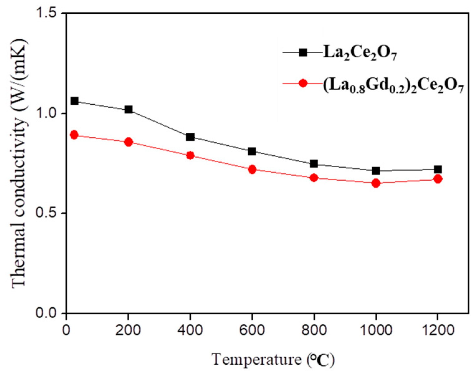
3.2. Thermal Conductivity

Free-standing LC and LGC coating specimens for thermal diffusivity measurements were prepared. Figure 7 shows the XRD patterns of as-fabricated TBCs. Both coatings consisted of fluorite phase. Figure 8 shows the thermal diffusivities of the two coatings. The values of the thermal diffusivity were the arithmetic means of three measurements. Since the error derived from the mean standard deviation of three measurements for each specimen was smaller than the symbols, the error bars were omitted for all thermal diffusivity data. As shown in Figure 8, the thermal diffusivity of the coatings decreased with the increase of the surrounding temperature from room temperature to 1200 °C, due to the inverse temperature dependence in this temperature range [34].
The thermal conductivities were calculated using Equation (1), as shown in Figure 9. The error bars were omitted for the same the reason. The LGC coating exhibited lower thermal conductivities than that of the LC coating, which was ~0.67 W/m·K at 1200 °C. It is well known that the thermal conductivity is proportional to the mean free path of phonon, according to the phonon thermal conduction theory [35]. In the LGC ceramics, Gd3+ take the site of La3+ in LC ceramics. The substitutional atoms existing in the lattice of LC can also reduce the mean free path of phonon, therefore leading to the decrease in thermal conductivity [24].

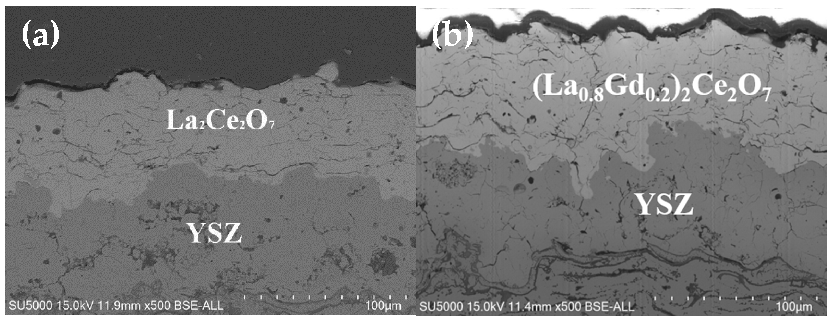
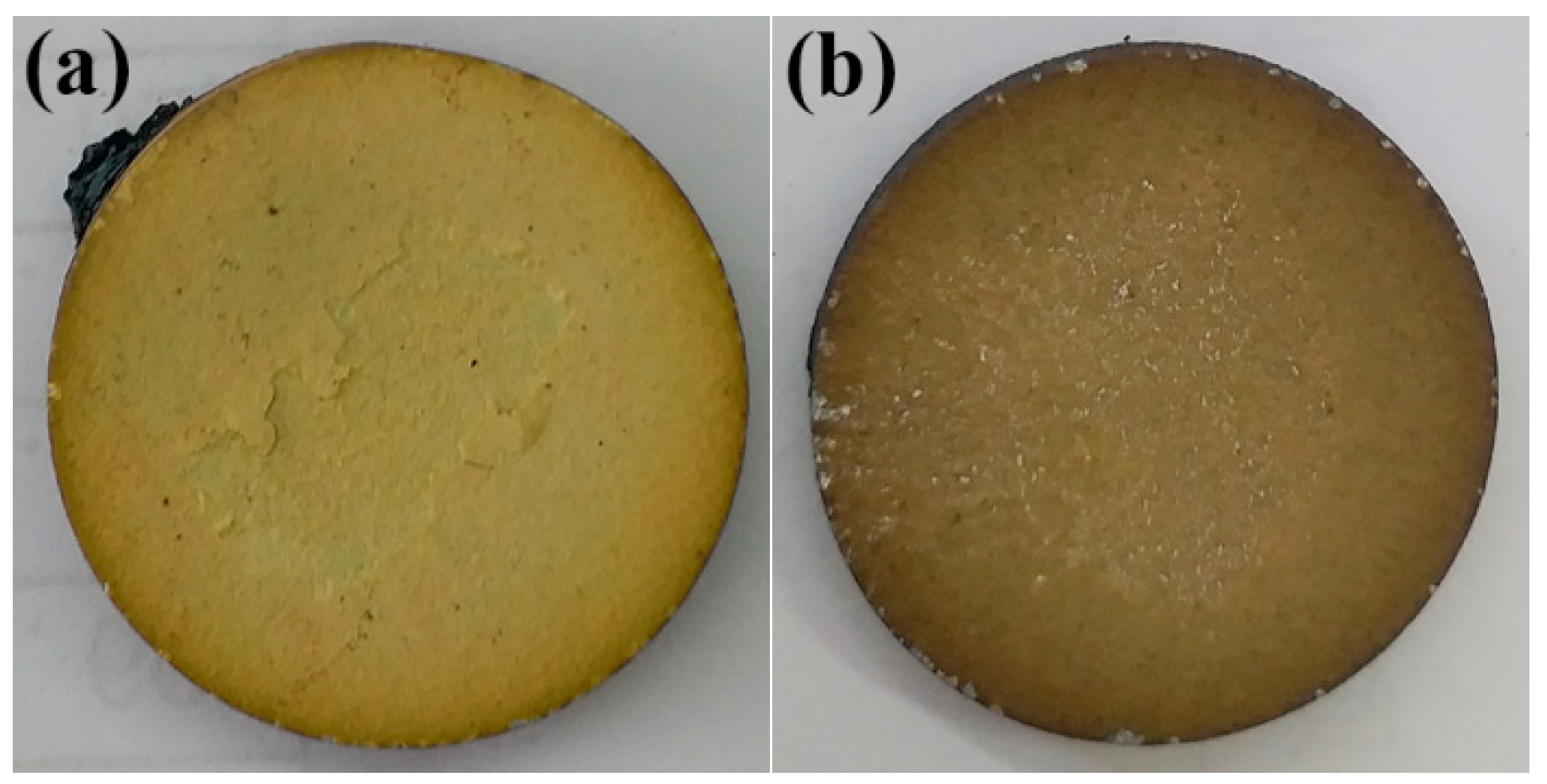
3.3. Thermal Shock Test of DCL TBCs

The (La0.8Gd0.2)2Ce2O7/YSZ (LGC/YSZ) TBCs were produced by APS to evaluate the thermal shock resistance ability and the La2Ce2O7/YSZ (LC/YSZ) TBCs were also tested for comparison. Figure 10 shows the cross-section micrographs of as-sprayed LGC/YSZ and LC/YSZ DCL TBCs. The coatings exhibited the typical layered structure. The thickness of the LGC layer, LC layer and YSZ layer were ~70 μm, ~60 μm, and ~70 μm, respectively.
Figure 11 displays the macro-image of the failed coatings after the thermal shock test. The LC/YSZ DCL TBCs reached failure after 68 thermal cycles at 1100 °C, while the LGC/YSZ DCL TBCs showed a longer thermal cycling lifetime at 109 cycles. Therefore, it can be inferred that Gd2O3 doping helped to improve the thermal shock resistance ability of the LC coating. It can be seen that both coating spallations were located in the center of the coating. The improvement of the cycling lifetime may be related to the better thermal expansion coefficients (TEC) of the LGC coating than that of the LC coating. The TEC of the LC showed a sudden drop between 200 °C and ~400 °C, which would lead to the formation of thermal stress during thermal cycles and, finally, result in the early failure of the coatings. When doping Gd2O3 in LC, the sudden drop of TEC disappeared and the LGC exhibited higher TEC than that of the LC. Both factors are beneficial to reduce the residual thermal stresses due to thermal expansion mismatch at the interface in thermal barrier coatings.
With the purpose of studying the failure mechanisms, surface morphologies of the failed LC/YSZ and LGC/YSZ DCL TBCs were examined, as shown in Figure 12. It can be observed that both coatings exhibited the same failure mode. A large area of the coating in both TBCs had already spalled off and the YSZ coat was exposed, as indicated by EDS analysis. Some net cracks were also observed, indicating that the failure of the coating was caused by a layer by-layer coating spallation.
Figure 13 shows the cross-section morphologies of the failed LC/YSZ and LGC/YSZ DCL TBCs. The spallation occurred in the topcoat, and the YSZ-NiCoCrAlY coatings remained intact, as determined by an EDS analysis. Although the bond coat was oxidized, a very thin TGO layer formed at the YSZ-NiCoCrAlY interface. Therefore, it should be inferred that oxidation of the bond coat was not the major reason for the failure. Due to the good thermal insulation performance of the LGC/LC coating as the top layer, substrate temperature was not high enough and thus the oxidation time was not long enough to form a thick TGO layer [36,37].
A layer by-layer coating spallation was observed in both coatings. Therefore, it can be inferred that the LC/YSZ and LGC/YSZ DCL TBCs had the same failure mode. It is reported that a layer by-layer coating spallation was caused by the sintering of the ceramic coating [22]. The sintering effect resulted in a contraction of the outer layer of ceramic coating during the thermal cycling, which caused the in-plane tensile stress in the outer layers and, finally, the formation of cracks perpendicular to the interface due to the restriction of the inner layers in the ceramic coating. When the in-plane tensile stress accumulated to some extent, the horizontal cracks in the outer layers developed, resulting in the spallation of the outer layers of the ceramic coating [22,38]. With thermal cycling rising, the process repeated and the coating spalled layer by layer.
According to the above results, the failure mode of the LGC/YSZ DCL TBCs was the same as that of the LC/YSZ DCL TBCs, which was still layer spallation due to the sintering of the ceramic coating. Gd2O3 doping helped to improve the thermal shock resistance ability of the La2Ce2O7 coating. The thermal shock resistance ability of the LGC/YSZ DCL TBCs can be mainly attributed to the improved thermal expansion coefficient of the LGC coatings, which can decrease the thermal expansion mismatch stresses in the coatings. Thermal conductivity also has some influence. The lower thermal conductivity of the LGC coatings compared with LC coatings can enhance the temperature drop across it and leads to the bond coat experiencing lower temperatures and, finally, corresponds to a weakened TGO growth and a decrease in the thermal expansion mismatch stresses [39]. Therefore, a decrease of the thermal conductivity causes the LGC/YSZ DCL TBCs to exhibit higher thermal shock cycles.

4. Conclusions

Due to the temperature limitations of the state-of-the-art 7YSZ, it is essential to develop new thermal barrier coatings (TBCs) to improve the efficiency of aircraft gas turbine engines. In this study, stoichiometric (La0.8Gd0.2)2Ce2O7 (LGC) coatings were prepared by atmospheric plasma spraying (APS), using optimized spray parameters and (La0.8Gd0.2)2Ce2.5O8 as a spray powder. The performance analysis results showed that LGC is a very promising candidate in this regard. The LGC coating exhibited lower thermal conductivities than that of the LC coating, which was ~0.67 W/m·K at 1200 °C. Furthermore, the LGC/YSZ DCL TBCs had a better thermal shock resistance ability than that of the LC/YSZ DCL TBCs, which was around 109 cycles at 1100 °C. The failure mode was similar to that of LC/YSZ DCL TBCs, however, which was still layer spallation in the top ceramic layer due to the sintering of the ceramic coating. In fact, the thermal cycling lifetime of the coating was greatly influenced by the microstructure, which determined by the spray parameter. Hence, the relationship between these two factors will be further studied to improve the thermal cycling lifetime of the LGC coating. To comprehensively examine the coating properties, further research must be performed, including: hardness, adhesiveness, a thermal expansion test, a hot corrosion test, and so on.

Author Contributions

Investigation, L.G.; formal analysis, F.J.; methodology, X.L. All authors have read and agreed to the published version of the manuscript.

Funding

This work was financially supported by the National Natural Science Foundation for the Young Scientist Fund of China (grant no. 51801012).

Institutional Review Board Statement

Not applicable.

Informed Consent Statement

Not applicable.

Data Availability Statement

Not applicable.

Acknowledgments

The authors would like to express their thanks to Haoran Peng for producing the LGC feedstocks.

Conflicts of Interest

The authors declare no conflict of interest.

References

  1. Padture, N.P.; Gell, M.; Jordan, E.H. Thermal barrier coatings for gas-turbine engine applications. Science 2002, 296, 280–284. [Google Scholar] [CrossRef]
  2. Bennett, T.D.; Yu, F. A nondestructive technique for determining thermal properties of thermal barrier coatings. J. Appl. Phys. 2005, 97, 1–12. [Google Scholar] [CrossRef]
  3. Brindley, W.J.; Leonharat, T.A. Metallugraphic techniques for evaluation of thermal barrier coatings. Mater. Character. 1990, 24, 93–101. [Google Scholar] [CrossRef]
  4. Miller, R.A. Thermal barrier coatings for aircraft engines: History and directions. J. Therm. Spray Technol. 1997, 6, 35–42. [Google Scholar] [CrossRef] [Green Version]
  5. Niessen, K.V.; Gindrat, M.; Refke, A. Vapor phase deposition using plasma spray-PVD. J. Therm. Spray Technol. 2010, 19, 502–509. [Google Scholar] [CrossRef]
  6. Hospach, A.; Mauer, G.; Vaßen, R.; Stöver, D. Columnar-Structured thermal barrier coatings (TBCs) by thin film low-pressure plasma spraying (LPPS-TF). J. Therm. Spray Technol. 2011, 20, 116–120. [Google Scholar] [CrossRef]
  7. Gupta, M.; Li, X.H.; Markocsan, N.B.; Kjellman, B. Design of high lifetime suspension plasma sprayed thermal barrier coatings. J. Eur. Ceram. Soc. 2020, 3, 768–779. [Google Scholar] [CrossRef]
  8. Fan, W.; Bai, Y. Review of suspension and solution precursor plasma sprayed thermal barrier coatings. Ceram. Int. 2016, 42, 14299–14312. [Google Scholar] [CrossRef]
  9. Scliulz, U.; Terry, S.G.; Levi, C.G. Microstructure and texture of EB-PVD TBCs grown under different rotation modes. Mater. Sci. Eng. A 2003, 360, 319–329. [Google Scholar] [CrossRef]
  10. Kulkami, A.A.; Goland, A.; Herman, H.; Allen, A.J.; Ilavsky, J.; Long, G.G.; Johnson, C.A.; Ruud, J.A. Microstructure-property correlations in industrial thermal barrier coatings. J. Am. Ceram. Soc. 2004, 87, 1294–1300. [Google Scholar]
  11. Wright, P.K.; Evans, A.G. Mechanisms governing the performance of thermal barrier coatings. Mater. Sci. 1999, 4, 255–265. [Google Scholar] [CrossRef]
  12. Vassen, R.; Cao, X.Q.; Tietz, F.; Basu, D.; Stöver, D. Zirconates as new materials for thermal barrier coatings. J. Am. Ceram. Soc. 2000, 83, 2023–2028. [Google Scholar] [CrossRef]
  13. Basu, D.; Funke, C.; Steinbrech, R.W. Effect of heat treatment on elastic properties of separated thermal barrier coatings. J. Mater. Res. 1999, 14, 4643–4650. [Google Scholar] [CrossRef]
  14. Schulz, U. Phase transformation in EB-PVD yttria partially stabilized zirconia thermal barrier coatings during annealing. J. Am. Ceram. Soc. 2000, 83, 904–910. [Google Scholar] [CrossRef]
  15. Friedrich, C.; Gadow, R.; Schirmer, T. Lanthanum hexaaluminate-a new material for atmospheric plasma spraying of advanced thermal barrier coatings. J. Therm. Spray Technol. 2001, 10, 592–859. [Google Scholar] [CrossRef]
  16. Cao, X.Q.; Vassen, R.; Jungen, W.; Schwartz, S.; Tietz, F.; Stöver, D. Thermal stability of lanthanum zirconate plasma-sprayed coating. J. Am. Ceram. Soc. 2001, 84, 2086–2090. [Google Scholar] [CrossRef]
  17. Guo, L.; Guo, H.B.; Peng, H.; Gong, S. Thermophysical properties of Yb2O3 doped Gd2Zr2O7 and thermal cycling durability of (Gd0.9Yb0.1)2Zr2O7/YSZ thermal barrier coatings. J. Eur. Ceram. Soc. 2014, 34, 1255–1263. [Google Scholar] [CrossRef]
  18. Cao, X.Q.; Vassen, R.; Fischer, W.; Tietz, F.; Jungen, W.; Stöver, D. Lanthanum-cerium oxide as a thermal barrier-coating material for high-temperature applications. Adv. Mater. 2003, 15, 1438–1442. [Google Scholar] [CrossRef]
  19. Liu, Z.G.; Ouyang, J.H.; Zhou, Y. Effect of gadolinia on phase structure and thermal conductivity of ZrO2-4.5 mol%Y2O3 ceramics. Mater. Letter. 2008, 62, 3524–3526. [Google Scholar] [CrossRef]
  20. Guo, H.B.; Wang, Y.; Wang, L.; Gong, S.K. Thermo-physical properties and thermal shock resistance of segmented La2Ce2O7/YSZ thermal barrier coatings. J. Therm. Spray Technol. 2009, 18, 665–671. [Google Scholar] [CrossRef]
  21. Gao, L.H.; Guo, H.B.; Gong, S.K.; Xu, H.B. Plasma-sprayed La2Ce2O7 thermal barrier coatings against calcium-magnesium-alumina-silicate penetration. J. Eur. Ceram. Soc. 2014, 34, 2553–2561. [Google Scholar] [CrossRef]
  22. Ma, W.; Dong, H.Y.; Guo, H.B.; Gong, S.K.; Zheng, X.B. Thermal cycling behavior of La2Ce2O7/YSZ double-ceramic-layer thermal barrier coatings prepared by atmospheric plasma spraying. Surf. Coat. Technol. 2010, 204, 3366–3370. [Google Scholar] [CrossRef]
  23. Ma, W.; Gong, S.K.; Xu, H.B.; Cao, X.Q. On improving the phase stability and thermal expansion coefficients of lanthanum cerium oxide solid solutions. Scr. Mater. 2006, 54, 1505–1508. [Google Scholar] [CrossRef]
  24. Zhang, H.S.; Chen, X.G.; Li, G.; Wang, X.L.; Dang, X.D. Influence of Gd2O3 addition on thermophysical properties of La2Ce2O7 ceramics for thermal barrier coatings. J. Eur. Ceram. Soc. 2012, 32, 3693–3700. [Google Scholar]
  25. Zhang, H.S.; Wei, Y.; Li, G.; Chen, X.G.; Wang, X.L. Investigation about thermal conductivities of La2Ce2O7 doped with calcium or magnesium for thermal barrier coatings. J. Alloys Comp. 2012, 537, 141–146. [Google Scholar] [CrossRef]
  26. Gao, L.H.; Deng, X.; Peng, H.R.; Zhang, D.M. Preparation and thermal shock resistance of Gd2O3 doped La2Ce2O7 thermal barrier coatings. Therm. Spray Technol. 2020, 4, 22–28. [Google Scholar]
  27. Schulz, U.; Saruhan, B.; Fritscher, K.; Leyens, C. Review on advanced EB-PVD ceramic topcoats for TBC applications. Int. J. Appl. Ceram. Technol. 2004, 1, 302–315. [Google Scholar] [CrossRef]
  28. Wang, J.S.; Sun, J.B.; Zhang, H.; Dong, S.; Jiang, J.; Deng, L.; Zhou, X.; Cao, X. Effect of spraying power on microstructure and property of nanostructured YSZ thermal barrier coatings. J. Alloys Comp. 2018, 730, 471–482. [Google Scholar] [CrossRef]
  29. Leitner, J.D.; Chuchvalec, P.; Sedmidubsky, D. Estimation of heat capacity of solid mixed oxides. Thermochim. Acta 2003, 395, 27–46. [Google Scholar] [CrossRef]
  30. Beele, W.; Marijnissen, G.; Lieshout, A.V. The evolution of thermal barrier coatings status and upcoming solutions for today’s key issues. Surf. Coat. Technol. 1999, 120–121, 61–67. [Google Scholar] [CrossRef]
  31. Kuroda, S.; Clyne, T.W. The quenching stress in thermally sprayed coatings. Thin Solid Films 1991, 200, 49–66. [Google Scholar] [CrossRef]
  32. Schlichting, K.W.; Padture, N.P.; Klemens, P.G. Thermal conductivity of dense and porous yttria-stabilized zirconia. J. Mater. Sci. 2001, 36, 3003–3010. [Google Scholar] [CrossRef]
  33. Wu, J.; Wei, X.Z.; Padture, N.P.; Klemens, P.G.; Gell, M.; García, E.; Miranzo, P.; Osendi, M.I. Low-thermal-conductivity rare-earth zirconates for potential thermal-barrier-coating applications. J. Am. Ceram. Soc. 2002, 85, 3031–3035. [Google Scholar] [CrossRef]
  34. Hong, S.J.; Kim, S.J.; Han, W.K.; Kang, S.G. Thermal properties of La2O3–YSZ powder fabricated by heterogeneous precipitation. J. Alloys Comp. 2009, 486, 543–548. [Google Scholar] [CrossRef]
  35. Nicholls, J.R.; Lawson, K.J.; Johnstone, A.; Rickerby, D.S. Methods to reduce the thermal conductivity of EB-PVD TBCs. Surf. Coat. Technol. 2002, 151–152, 383–391. [Google Scholar] [CrossRef] [Green Version]
  36. Xu, Y.-X.; Liu, T.; Yang, G.-J.; Li, C.-J. Thermal stability of plasma-sprayed La2Ce2O7/YSZ composite coating. Ceram. Int. 2016, 42, 7950–7961. [Google Scholar] [CrossRef]
  37. Dong, H.; Wang, D.; Pei, Y.; Li, H.; Li, P.; Ma, W. Optimization and thermal cycling behavior of La2Ce2O7 thermal barrier coatings. Ceram. Int. 2013, 39, 1863–1870. [Google Scholar] [CrossRef]
  38. Nissley, D.M. Thermal barrier coating life modeling in aircraft gas turbine engines. J. Therm. Spray Technol. 1997, 6, 91–98. [Google Scholar] [CrossRef] [Green Version]
  39. Ganvir, A.; Joshi, S.; Markocsan, N.; Vassen, R. Tailoring columnar microstructure of axial suspension plasma sprayed TBCs for superior thermal shock performance. Mater. Des. 2018, 144, 192–208. [Google Scholar] [CrossRef]
Figure 1. XRD patterns of the coatings deposited using three spray powders with different composition.
Coatings 11 01186 g001
Figure 2. The relationship of the (La + Gd)/Ce ratio between the spray powders and coatings.
Coatings 11 01186 g002
Figure 3. Cross-section morphologies of thermal barrier coatings deposited at different spray distances: (a,b) 90 mm, (c,d) 100 mm, and (e,f) 110 mm.
Coatings 11 01186 g003
Figure 4. (La + Gd)/Ce ratio in the as-sprayed coatings versus spray distance.
Coatings 11 01186 g004
Figure 5. Cross-section morphologies of thermal barrier coatings deposited using different spray power: (a,b) 38 kW, (c,d) 42 kW, and (e,f) 46 kW.
Coatings 11 01186 g005aCoatings 11 01186 g005b
Figure 6. (La + Gd)/Ce ratio in the as-sprayed coatings versus spray power.
Coatings 11 01186 g006
Figure 7. XRD patterns of as-fabricated double-ceramic-layer (DCL) thermal barrier coatings (TBCs).
Coatings 11 01186 g007
Figure 8. Thermal diffusivity values of the LC and LGC coatings.
Coatings 11 01186 g008
Figure 9. Thermal diffusivity values of the LC and LGC coatings.
Coatings 11 01186 g009
Figure 10. Cross-section micrographs of as-sprayed DCL TBCs: (a) La2Ce2O7/YSZ (LC/YSZ), and (b) (La0.8Gd0.2)2Ce2O7/YSZ (LGC/YSZ).
Coatings 11 01186 g010
Figure 11. The macro-image of the failed coatings after thermal shock test: (a) LC/YSZ after 68 thermal cycles, and (b) LGC/YSZ after 109 thermal cycles.
Coatings 11 01186 g011
Figure 12. Surface morphologies of the failed thermal barrier coatings: (a) LC/YSZ, and (b) LGC/YSZ.
Coatings 11 01186 g012
Figure 13. Cross-section morphologies of the failed thermal barrier coatings: (a) LC/YSZ, and (b) LGC/YSZ.
Coatings 11 01186 g013
Table 1. Spray parameters of ceramic coating.
Plasma Gas (L/min)Current (A)Power (kW)Spray
Distance (mm)
Preheating
Temperature (°C)
Ar 38 H2 1460042100200~250 °C
65046100
55038100
6004290
Publisher’s Note: MDPI stays neutral with regard to jurisdictional claims in published maps and institutional affiliations.

