Article

Analysis of Film Forming Law and Characteristics for an Air Static Spray with a Variable Position of the Plane

School of Mechanical Engineering, Yancheng Institute of Technology, Yancheng 224051, China
*
Author to whom correspondence should be addressed.
Coatings 2021, 11(10), 1236; https://doi.org/10.3390/coatings11101236
Submission received: 28 August 2021 / Revised: 27 September 2021 / Accepted: 4 October 2021 / Published: 12 October 2021

Abstract

:
In order to accurately establish the film thickness distribution model of a static spraying plane with air gun displacement, the film forming law and characteristics of the static spraying plane with air gun displacement were analyzed. The spray simulation model was established by the Euler–Euler method, and the spray process and film forming condition were calculated. The numerical simulation results show that oblique spraying has a large influence on the near-surface liquid velocity. With the increase in the spray angle, the droplets at the edge of the torch diffuse to the inclined direction, and the uniformity of the coating distribution becomes worse. Spraying height has a large influence on droplet trajectory. The coating thickness decreased significantly with the increase in spraying height, and the coating diffused in the air increased. With the increase in spraying height, the more obvious the droplet diffusion at the edge of the torch, the worse the uniformity quality of the coating. In order to ensure better spraying quality, the spraying height and angle should be controlled within a reasonable range at the same time. Spraying experiments verified the film forming law and characteristics of static spraying with gun displacement.

1. Introduction

Robotic spraying technology is widely used in automobile, aviation, aerospace, shipbuilding and other manufacturing fields because of its advantages of stable spraying quality, high spraying efficiency and automation [1,2]. The spray objects are often the surfaces of products with complex free-form features such as fighter fuselages and car bodies. Spraying complex curved surfaces often uses variable position spraying. Therefore, in order to realize the digital spraying trajectory, planning in the offline programming mode, revealing the spraying film formation rules and characteristics under a specific spraying mode, is the first key problem to be solved [3].
With the continuous development of modern industry, the spraying technology used for coating deposition is mainly divided into air spraying, airless spraying, thermal spraying and electrostatic spraying. Thermal spraying technology is an important technology in the field of surface engineering. The powder material is heated to a plastic or melting state by thermal spraying equipment, and then sprayed on the surface of the workpiece to form a protective layer. Mostaghimi [4] proposed a complete high-speed oxygen fuel (HVOF) spraying process model. Kanta [5] compared the application of artificial neural networks and fuzzy logic in plasma spraying and found that artificial intelligence (AI) was the appropriate method to predict spraying parameters to obtain the required coating characteristics. In the study by Ren [6], according to the needs of aero-engine hot end structure, (Y1/4Ho1/4Er1/4Yb1/4)2SiO5 solid solution was selected as a multifunctional coating material. Electrostatic spraying technology is divided into electrostatic air spraying and electrostatic spinning cup spraying. Studies have shown that the atomization effect of electrostatic air spraying coating is better than that of the electrostatic rotary cup, which has become an increasingly widely used spraying technology in recent years [7].
The air spraying method is currently widely used because of its good atomization effect and wide application range [8]. Spraying parameters mainly include central atomization hole pressure, fan surface control hole pressure, paint flow, spraying distance, spraying angle, spray gun moving speed, etc. Zeng et al. studied multi-parameter spray gun trajectory optimization based on boundary constraints [9]. Due to the complexity of the film forming process of air spraying, the combination of CFD numerical simulation and spraying experiment is mainly used to study how to establish a physical model to accurately predict the coating deposition rate [10,11]. The CFD simulation method is used to study the film forming process of spraying from the mechanism, and the thickness of the coating is calculated by using computational fluid dynamics combined with experimental data. It is theoretically applicable to the simulation of the film forming process of spraying under various conditions [12]. In order to study the film forming mechanism of plane air spraying, the trajectory of spray particles was simulated by the Lagrange method [13]. Fogliati [14] considered the influence of air and fog fields and simulated the transfer and film forming process of coatings on the plane by the Lagrange method. Ye [15] adopted the Euler–Lagrange method to numerically calculate the impact process of coating droplets on the plane under the influence of two-phase flow of the air field and fog field. Barry [16] used s realizable k-ε turbulence model to simulate the impact process of a single jet on the target plane, and studied the influence of air flow rate, spraying height and other parameters on the thickness distribution of the coating during air spraying jet impact. In order to study the film forming mechanism of regular surface air spraying, Chen Yan et al. used the Euler-Euler method [17,18] and the Euler–Lagrangian method [19] to study the film forming rules and characteristics of cylindrical and spherical surfaces with different sizes. The above research only focuses on the case that the spray gun is perpendicular to the spray surface and the position of the spray gun is fixed. However, the law and characteristics of static spray film formation under the influence of spray height and spray angle are not studied. At this stage, the mathematical model of coating film deposition cannot quickly predict the coating film deposition rate under various spraying distances and spraying inclination angles. The shortcomings have been unable to meet the needs of trajectory planning for complex surface modification [20].
In this paper, the Euler–Euler method is used to establish the simulation model of static air spraying with displacement posture. Based on the simulation model, the static spraying process and film formation of variable posture are simulated and calculated. The simulation data were analyzed to summarize the influence of different spraying height and spraying angle on coating quality and coating thickness distribution. The adjustable range of spraying height was analyzed when the spraying angle was from 0° to 30°. It lays a theoretical foundation for the establishment of a prediction model for the thickness distribution of the spray gun spraying with variable positions. Finally, the feasibility of the simulation model in this paper is verified by spraying experiments.

2. Calculation Model of Spraying Flow Field

There is a velocity difference between the liquid phase and sprayed air during air spray gun spraying. Under the action of air shock, the liquid phase forms tiny droplets after one-time atomization and two-time atomization, which are transported by air to the surface of the workpiece to form liquid film. The gas phase and liquid phase are regarded as continuous phases in the Euler–Euler model, and the liquid phase and gas phase are regarded as continuous mediums of mutual penetration. Spraying models include the spray field model, liquid film model and impact splash model. The spray fog field motion model mainly describes the movement and transportation process of the liquid phase under the action of air, the liquid film model describes the process of the liquid phase being transported to the wall to form a liquid film, and the impact splash model describes the process of splashing after the liquid phase collides with the surface of the workpiece.

2.1. Basic Control Equation

The gas phase and liquid phase are regarded as continuous mediums in spraying, which must meet the basic control equations in fluid mechanics. Based on the continuum model of fluid mechanics, the following control equations are established: the mass conservation equation and momentum conservation equation [21].
The basic control equation is as follows:
The equation of mass conservation
α q ρ q t + · ( α q ρ q υ q ) = 0
In the formula, t is time, α q is the volume fraction of the q phase, ρ q is the density of the q phase, υ q is the speed of the q phase. When q = g or d, g and d represent the gas and liquid phases, respectively.
The momentum conservation equation
t ( α q ρ q υ q ) + ( α q ρ q υ q υ q ) = α q p + · τ q + α q ρ q g + F q t d + F q
In the formula, p is the shared pressure; τ q is the viscous stress of the q phase; F q t d is the turbulent dispersion force of the q phase; F q is the interphase force of the q phase. When q = g or d, g and d represent the gas and liquid phases, respectively.
The interphase force F q is the sum of the drag force F d , the lifting force F l and the virtual mass force F v . This study ignores the lifting force F l and the virtual mass force F v , and only considers the drag force caused by the speed difference between the two phases.
F d = 0.75 C d α q ρ q | ν p ν q | ( ν p ν q )
In the above formula: C d is the drag coefficient, which is taken as 0.44 in this study.

2.2. The Basic Equation of Compressible Flow

When the high-pressure gas is sprayed from the nozzle, the flow velocity can be close to the sound velocity. The compressibility of gas has a large influence on flow, so the compressibility of gas must be considered.
The compressible flow is generally described by the total pressure P0 and the total temperature T0. For the ideal gas, the relationship between total pressure P0, total temperature T0, static pressure Ps, and static temperature Ts can be described by the following equation [22]:
p 0 p s = exp ( T s T 0 C p T d T R )
When the heat capacity Cp is constant, it can be obtained from Equation (4):
p 0 p s = exp [ 1 + γ 1 2 M 2 ] γ γ 1
T 0 T s = 1 + γ 1 2 M 2
In the above formula, γ is the gas adiabatic index and M is the Mach number.

2.3. Turbulence Model

The equations described above are derived under laminar flow, and the actual fluid motion is often turbulent. The biggest feature of turbulent flow is its nearly infinite physical scale and mathematically strong nonlinearity. When the air flow is in a turbulent state, in addition to establishing the fluid motion control equation, it is necessary to establish the corresponding turbulence model to close the momentum equation. The standard k- ε turbulence model [23] is used here. In the standard k- ε   turbulence model, k represents the turbulent kinetic energy and   ε   represents the turbulent dissipation rate. The equation is as follows:
t ( ρ m κ ) + · ( ρ m ν m κ ) = ( μ t , m σ κ κ ) + G κ , m ρ m ε + ε m
t ( ρ m ε ) + · ( ρ m ν m ε ) = ( μ t , m σ ε ε ) + ε κ ( C 1 ε G κ , m G 2 ε ρ m ε ) + ε m
In the formula, μ t , m is the turbulent viscosity; σ ε and σ κ represent the Prandtl number corresponding to the turbulent kinetic energy k and the dissipation rate ε ; G κ , m represents the production terms of turbulent kinetic energy k caused by the average velocity gradient and buoyancy; ε m represents the additional term between two phases, including the pulsating expansion in compressible turbulence and the custom source term; C 1 ε , G 2 ε are empirical constants; ν m represents the air kinematic viscosity.

2.4. Wall Liquid Film Model

The liquid phase in the two-phase flow of the spray flow field is transported to the surface of the workpiece to form a liquid film. In order to predict the liquid film formed after the liquid phase accumulates on the surface of the workpiece and the movement of the liquid film, the liquid film formation process adopts the wall surface liquid film model. The liquid film satisfies the mass conservation equation and the momentum conservation equation. When the liquid in the spray flow field contacts the wall surface, its mass and momentum will be added as source terms to the mass conservation equation and momentum conservation equation of the liquid film.
The mass conservation equation
h t + s · ( h · V l ) = m ˙ s ρ 1
m ˙ s = α d ρ d V d n A
In the above formula: subscript l represents the liquid film; ρ 1 is the density of the liquid film; h is the height of the liquid film; V 1 is the average velocity of the liquid film; m ˙ s is the mass source of unit wall area; α d is the liquid volume fraction; ρ d is the liquid phase density; V d n is the velocity of the liquid phase perpendicular to the wall; A is the area of the wall.
The momentum conservation equation
h V l t + s · ( h · V l V l ) = h s P L ρ l + 3 2 ρ l τ f s 3 ν l h V l + q ˙ s ρ l
q ˙ s = m ˙ s V d
In the above formula: the left side of the equation is transient and convection occurs. The first item on the right side of the equation represents the action of air flow pressure and liquid film surface tension, the second item represents the action of viscous shear force at the air–liquid film interface, the third item represents the action of viscous force in the liquid film, and the fourth item represents the action of liquid film momentum source. q ˙ s is the momentum source. V d is liquid velocity.

3. Simulation of Static Variable Position Spraying

3.1. Simulation Method

In ANSYS Fluent software (2020 R1), the Euler–Euler model for liquid phase tracking includes steady and unsteady two modes. The steady-state mode predicts the distribution of discrete phases in a fixed and convergent continuous-phase flow field, which cannot realize the coupling of two phases. The unsteady state model can calculate the continuous phase and discrete phase alternately to realize the coupling of the two phases. In this paper, the unsteady mode is used to obtain more accurate simulation results.

3.2. Computation Domain and Grid Division

The 3D model of air cap of spray gun was established in SolidWorks software (2014). In this simulation experiment, the spray flow field is conical, so the fan control hole in the original actual model is omitted [24]. A 3D model is shown in Figure 1a. The central hole of the air cap is the spray pinhole and the coating inlet, and the aperture is 0.8 mm. The annular central atomizing hole is outside the central hole of the air cap, with an outer diameter of 2 mm and an inner diameter of 1.6 mm. There are two auxiliary atomizing holes on both sides of the central atomizing hole, and the aperture is 0.5 mm.
The calculation domain of dip spraying is hexahedral structure, as shown in Figure 1b. The surface to be sprayed is the 200 mm × 300 mm plane, and the gun attitude can be adjusted by the physical model of the gun. The tetrahedral mesh is used to mesh the spray gun and the computational domain. Considering the calculation accuracy and convergence rate, the local grids with spraying surface and spraying gun are encrypted. The computational domain grid is divided by global grid size control. The average element quality of the grid is 0.88, the minimum orthogonal quality is 1.9, and the skewness is 0.23. Increasing the number of grids cannot significantly improve the calculation accuracy.

3.3. Calculation Method and Parameter Setting

This model adopts transient calculation and pressure solver. The gas phase is ideal gas air and the liquid phase is spray transport particles. The liquid particle diameter data in this paper are from the experimental measurement data of Hicks [25]. The average particle size of the liquid phase is 20 μm. Liquid viscosity is 0.1 kg/(m · s). Density is 1.2 × 10³ kg/m3. Gravity is 9.81 m/s.
The model adopts Eulerian multiphase flow model, the Eulerian liquid film model and k-e turbulence model. The Eulerian liquid film model is set to collect liquid particles, the maximum liquid film thickness is less than 0.5 mm, and the initial liquid film velocity is 0 m/s. The spray gun coating inlet was set as the mass inlet, the mass flow rate of the liquid phase was set as 2 × 10⁻³ kg/s, and the mass flow rate of air was set as 5 × 10⁻⁶ kg/s. The turbulence intensity was set to be 15%, and the hydraulic diameter was set to be 0.002 m. The central atomization hole and auxiliary atomization hole are set as pressure inlet, and the inlet pressure is 140 kPa. The spray workpiece is the bottom, and the wall boundary condition is Eulerian wall film. The initial liquid velocity is 5 m/s and the spraying time is 0.5 s. The total time step is set to 5000, and the time step is set to 0.0001. Convergence is considered when the residual error is less than 1 × 10⁻⁴.

4. Analysis of Simulation Results

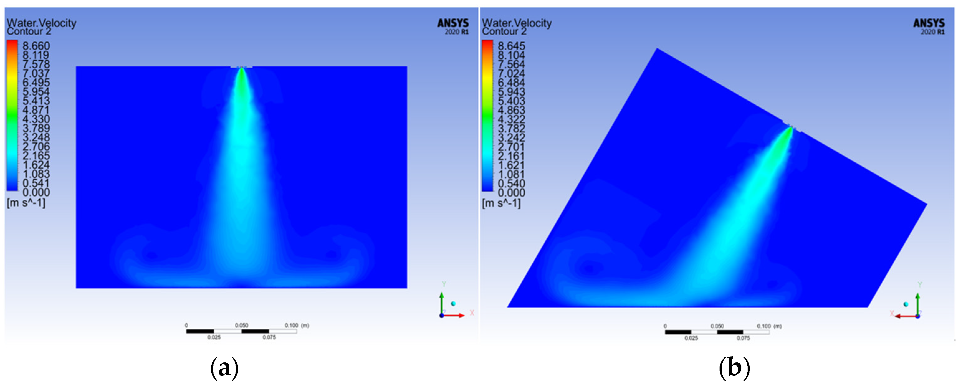
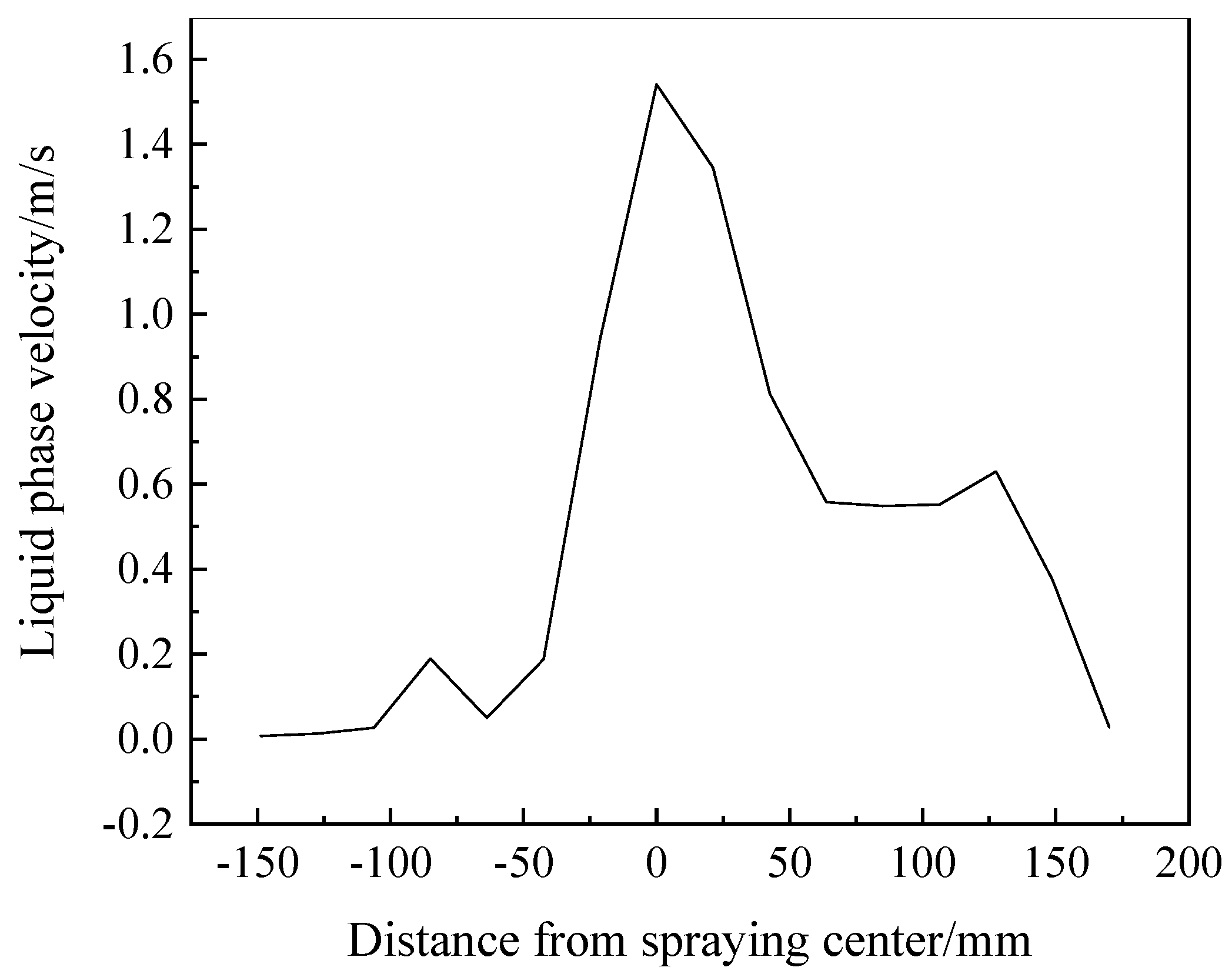
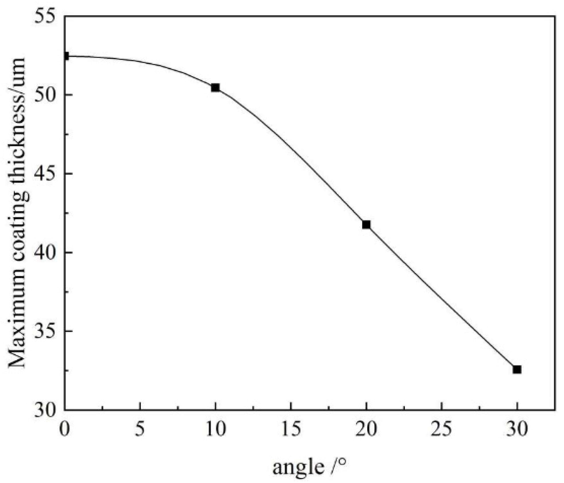
4.1. Effect of Spray Angle on Spray Field

In this paper, the spray gun model only includes the central atomizing hole and the auxiliary atomizing hole. Therefore, under the action of the air flow in the atomizing hole, the liquid phase is broken and atomized twice to form a circular liquid film. The droplet forms a conical spray torch under the transportation of airflow, and the cross section of the spray torch is approximately circular. When spraying at a dip-angle, the workpiece crosses the torch at a certain angle, without considering other factors, forming an elliptical liquid film, as shown in Figure 2.
The distribution of fog field is affected by spraying angle. When the workpiece is sprayed with the dip angle, most liquid particles diffuse in the direction of the dip angle. The velocity distributions of vertical spray and dip spray are shown in Figure 3.
There was no significant difference in the distribution of the fog field between oblique spraying and vertical spraying in the first half of droplet transportation. The influence of spraying angle on the fog field distribution mainly occurs at the final stage of liquid transportation, as shown in Figure 3. Before the droplet collides with the workpiece, the droplet will diffuse in the X and Z directions under the action of airflow, as shown in Figure 3b. Compared with the liquid velocity distribution of dip angle spraying and vertical spraying, it is obvious that, under the action of dip angle, there are more droplets diffused in the X direction and the velocity is larger, which may affect the uniformity and quality of the coating during dip angle spraying. In order to further analyze the fog field near the surface of the workpiece, the velocity vector distribution of the liquid phase at 20 mm from the wall of the workpiece in Figure 4 was studied, and the velocity curve of the fog field shown in Figure 5 was obtained.
It can be seen from Figure 5 that the droplet velocity at the central axis of the torch is the largest. The further away from the central axis that spraying occurs, the smaller the droplet velocity is, which is almost zero. When the droplet is transported to the vicinity of the workpiece surface, the droplets with higher speed diffuse in the positive X direction, and the droplets with lower speed diffuse in the negative X direction. The spraying angle has little effect on the velocity of droplets close to the central axis of the torch. The spray angle has a great influence on the droplet velocity far from the center axis of the torch, and the maximum difference is 0.4 m/s.

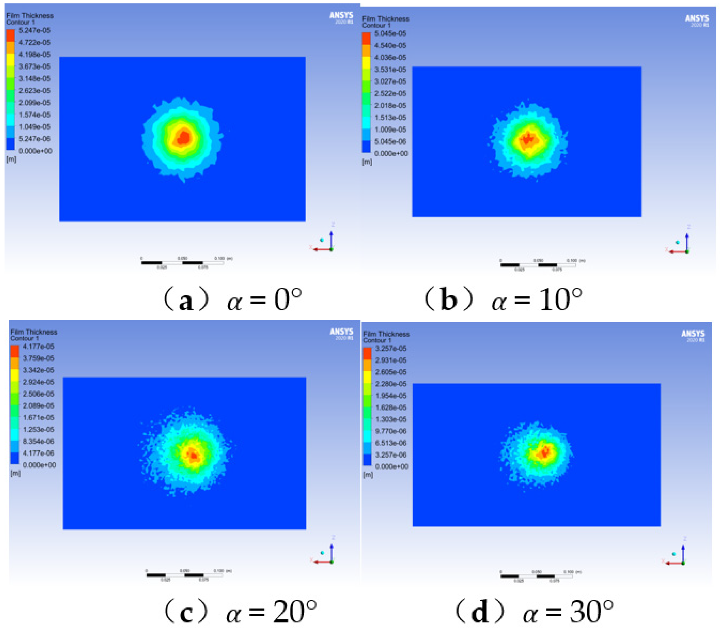
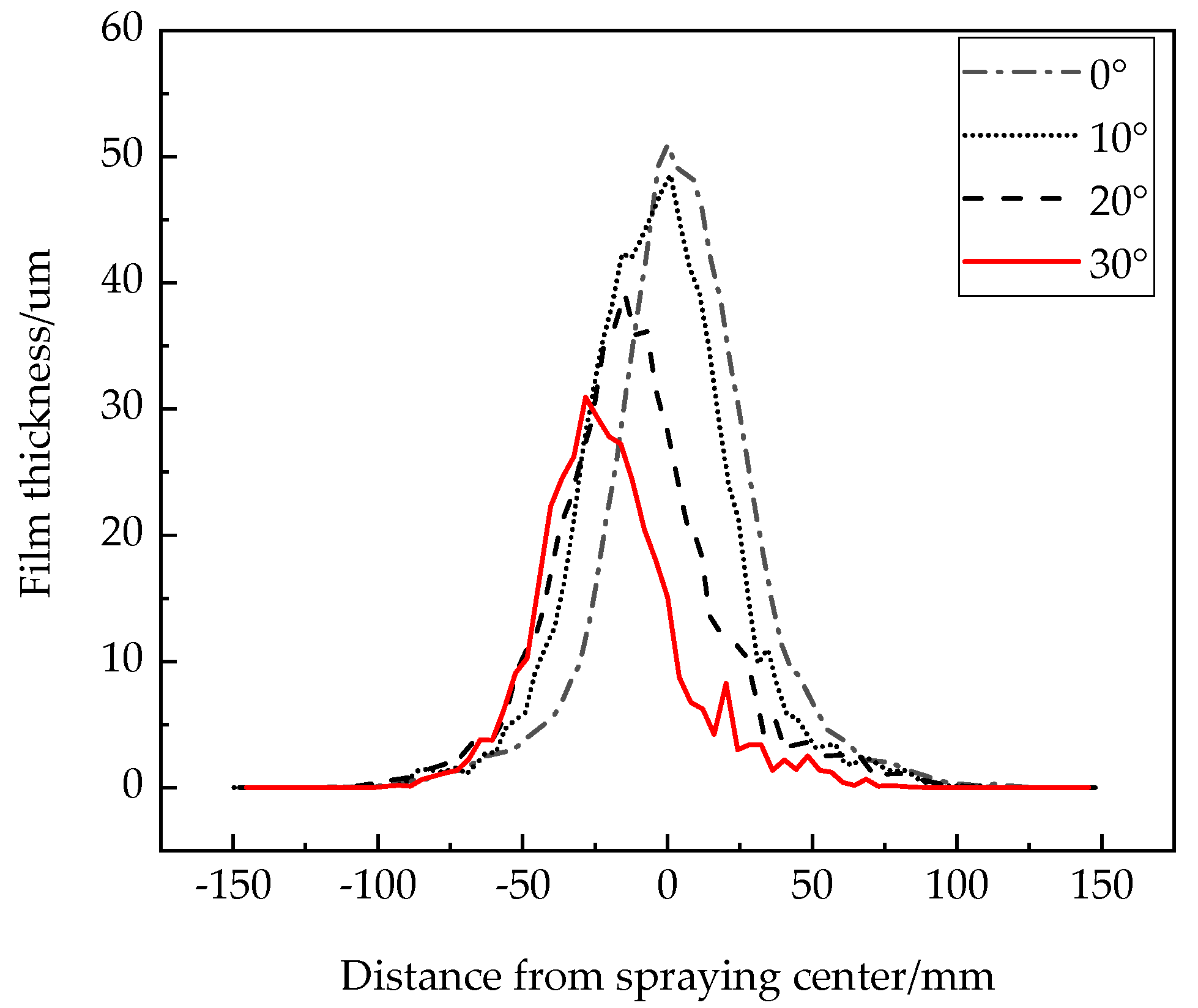
4.2. Effect of Spray Angle on Uniformity of Coating Distribution

The influence of dip angles of 0°, 10°, 20° and 30° on the uniformity of film distribution was analyzed when the spraying height was fixed at 200 mm, as shown in Figure 6.
In order to analyze the change in film thickness distribution under the influence of spraying dip angle more clearly, the film thickness in the X-axis direction was collected to form a fitting curve, and the curve of the maximum film thickness with the change in spraying dip angle was fitted, as shown in Figure 7 and Figure 8.
It can be seen from Figure 7 that the coating thickness distribution curve shows an uneven trend with the increase in spray angle. Thus, the existence of spray angle will lead to an uneven distribution of the coating. When the spraying inclination angle exceeds about 20°, the excessively large inclination angle will cause the droplets to spread under the action of the gas field, and the uniformity of the coating film distribution will become worse, resulting in more obvious sudden changes in the curve.
It can be seen from Figure 8 that the coverage area of the coating film gradually increases with the increase in the spray inclination, and the maximum coating film thickness decreases in an approximately parabolic manner.

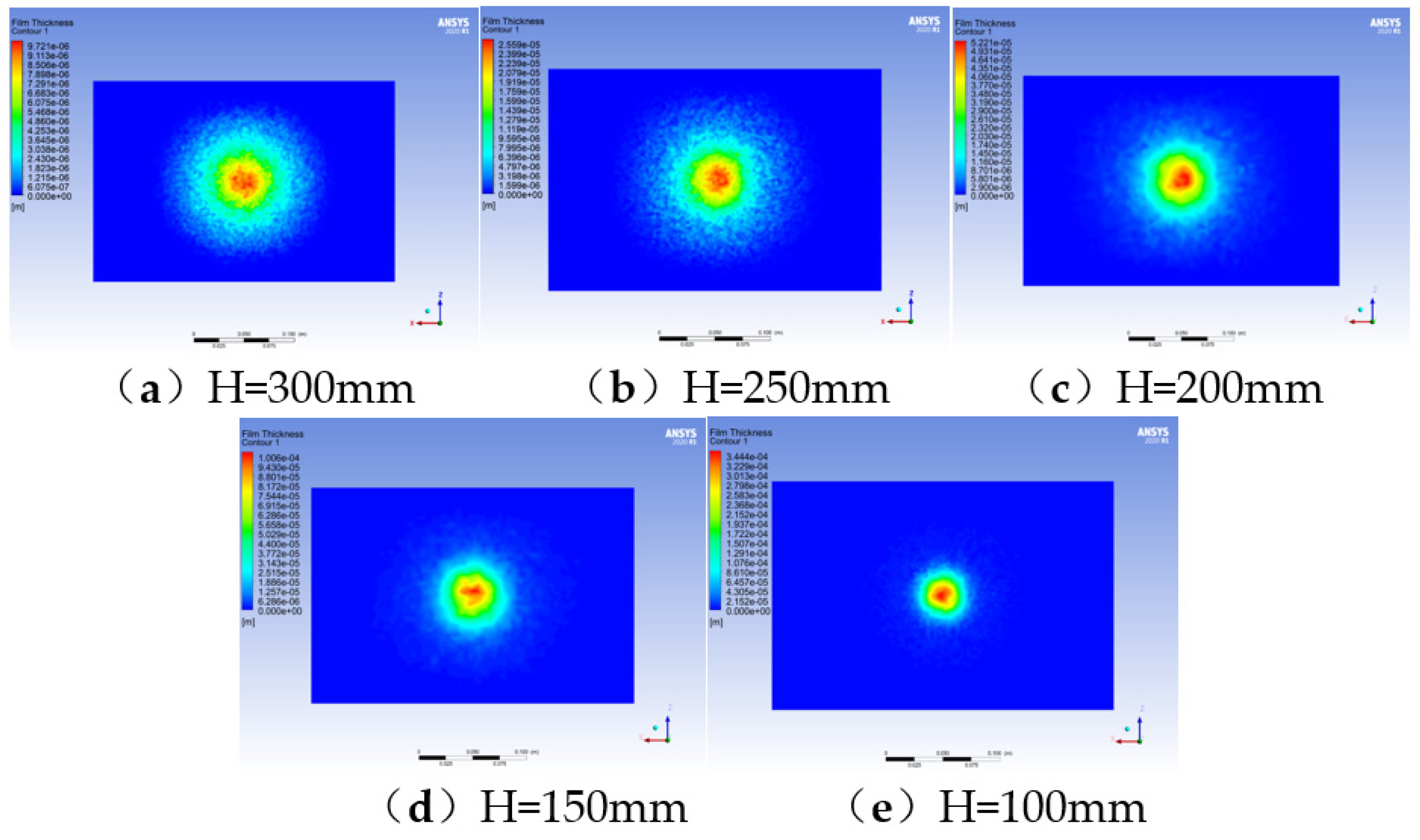
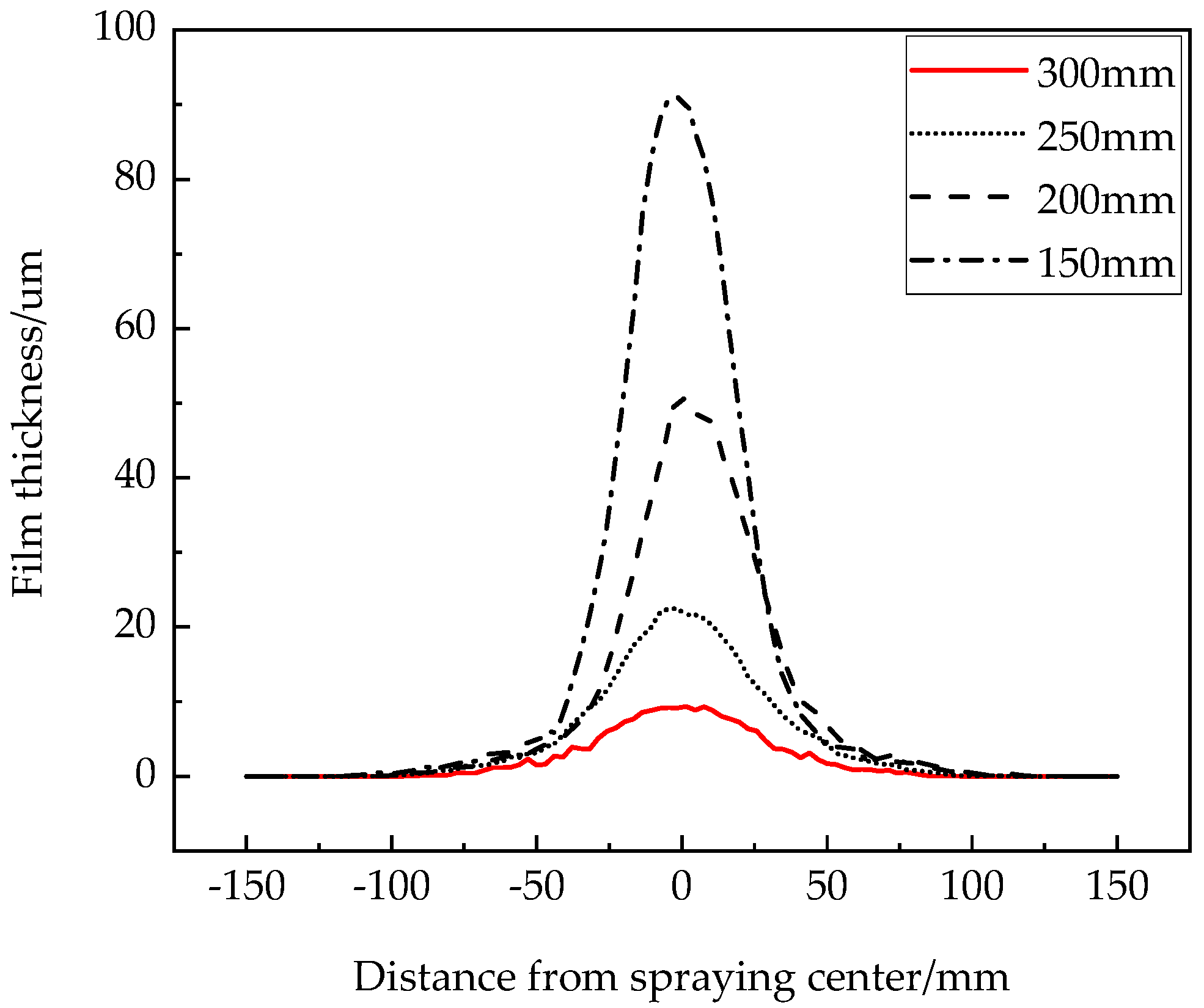
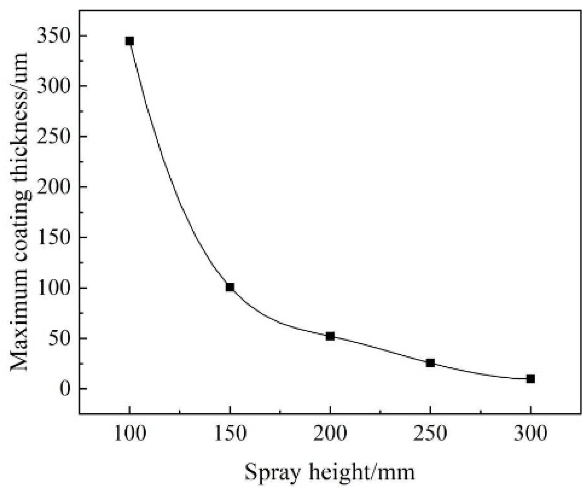
4.3. The Effect of Spraying Height on the Uniformity of Coating Film Distribution

In order to further explore the influence of spraying height on coating quality, the coating uniformity quality was analyzed when the spraying angle was fixed at 0° and the spraying heights were 300 mm, 250 mm, 200 mm, 150 mm and 100 mm. Figure 9 shows that the coating coverage increases with the increase in spraying height, and the coating at the edge of the coating coverage is gradually diffused, and the uniformity of the coating is variable. The main reason is that the droplets cannot be transported according to the original diffusion trajectory due to the influence of air field during transportation. On the contrary, with the decrease in spraying height, the coating coverage is smaller, the coating adhesion is more concentrated, and the coating diffused in the edge area of coating coverage decreases. In theory, it has good coating uniformity but, in practice, the coating thickness at the center of the coating is too large to produce a hanging phenomenon, which is not conducive to obtaining better coating quality.
In order to further analyze the change of coating thickness distribution under the influence of spraying height, the coating thickness in the X-axis direction was collected to form a fitting curve, and the curve of maximum coating thickness with spraying height was fitted, as shown in Figure 10 and Figure 11. From Figure 10, it can be seen that the coating thickness curve shows an uneven trend with the increase in spraying height. Especially when the spraying height is more than 250 mm, the coating thickness curve fluctuates drastically at both ends. The main reason is that, with the increase in spraying height, the droplet is greatly affected by the air field around the torch during transportation, thus affecting the uniformity of the coating.
With the increase in spraying height, the maximum coating thickness decreases in an approximately inverse function. The variation of the maximum film thickness is sensitive when the spraying height is between 100 mm and 150 mm, as shown in Figure 11.

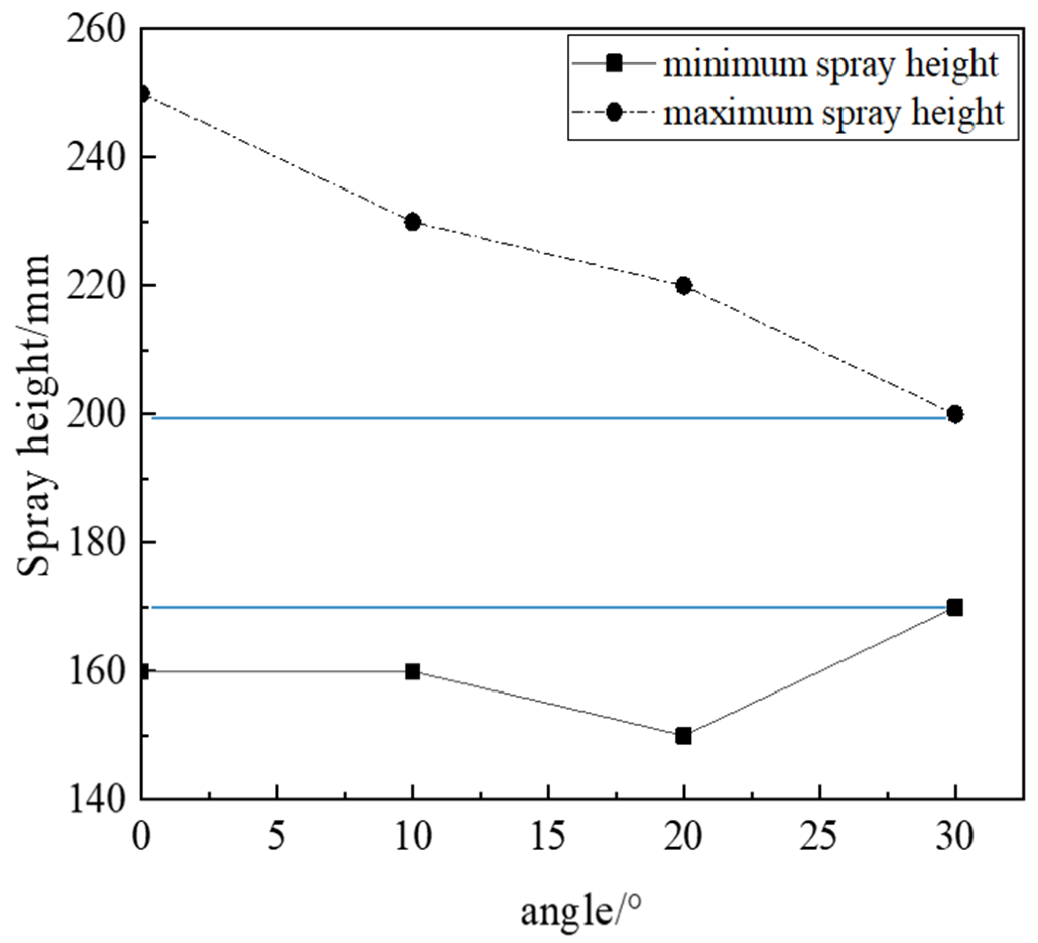
4.4. The Combined Effect of Spray Angle and Height on the Uniformity of Coating Film Distribution

From the above analysis, it can be seen that the careful selection of spraying height and spraying angle is essential to form a better coating distribution uniformity quality. In order to obtain an adjustable range of spraying height and spraying angle with good film distribution uniformity quality to meet the needs of trajectory planning of robot gun displacement spraying, the orthogonal test method is used to study the influence of spraying angle and height on film distribution uniformity at the same time [26]. In the range of spraying inclination angle from 0° to 30°, several groups of simulation experiments were conducted by changing the spraying height. The selected gun position parameters are shown in Table 1. The maximum coating thickness after spraying experiment is too small, indicating that the adhesion rate of coating particles on the surface is low, and, if it too large, the coating surface easily to produces film hanging. Therefore, the standard with which to judge the uniformity of coating distribution is as follows: the maximum thickness of the coating is between 20 and 100 μm. The coating has a complete molding boundary, and as such is round and oval shaped. The film is smooth, and there no hanging, bulge or depression.
By measuring the maximum coating thickness obtained by each simulation and according to the coating distribution uniformity quality standard set above, the relationship between the adjustable range of spraying height and spraying inclination is obtained, as shown in Figure 12.
It can be seen from the above figure that with, the increase in spraying angle, the adjustable range of spraying height gradually becomes smaller. The vertical spraying height can be adjusted from 250 to 160 mm. The maximum spraying height is obviously affected by spraying angle. With the increase in spraying angle, the maximum spraying height gradually decreases, and the minimum spraying height first decreases and then increases. With the decrease in spraying height, the adjustable range of spraying angle is larger. When the spraying height is between 200 and 170 mm, the spraying angle can be adjusted from 0° to 30°.

5. Spraying Experiment

In order to verify the correctness of the simulation model, the static spraying experiment of gun displacement was carried out. An air spray gun was used in the experiment. The deposition material was a commercial coating with water as the solvent or dispersion medium, commonly known as water paint. The coating is deposited on the surface of the workpiece by air atomization. The 6-axis industrial robot is used to adjust the position of the spray gun and spray the workpiece. The experimental platform is shown in Figure 13. The end effector was an Anest Iwata Spray Gun, the coating was water paint, the viscosity value was 0.1 pa·s. The spraying height was set to 200 mm, and the spraying angles were adjusted to 20° and 30° for the spraying test. The spray gun has two air inlets and one coating inlet. The control cabinet controls the solenoid valve to control the nozzle inlet path. Air compressor supply pressure was 0.2 Mpa; spraying time was 0.5 s. After the spraying test was completed, the workpiece was left alone for 24 h, and the coating thickness gauge was used to measure every 5 mm in X direction after the coating had fully solidified.
The comparison between the experimental results and the simulation results shows that the simulation results are basically consistent with the experimental results in the coating distribution shape, as shown in Figure 14. The maximum relative errors of coating thickness between the two groups of spraying experiments and simulation results were 10% and 9.5%, indicating that the simulation results and experimental results were consistent in the distribution of coating thickness. The maximum relative error here refers to the ratio of the absolute value of the difference between the simulation data point and the spray test data point to the spray test data point.

6. Conclusions

(1)
The spraying experiment results show that the simulation results are in good agreement with the experimental results, which proves the feasibility and effectiveness of the simulation model established in this paper. Therefore, the simulation method can be used to obtain the film thickness distribution law of static spraying with gun displacement.
(2)
In the field of automobile manufacturing, the variable position spraying method is usually used to spray the surface of products with complex free-form surface characteristics of the automobile body. Spraying angle and spraying height are the main reasons for the diffusion at the edge of the coating coverage. Therefore, the spraying height and spraying angle should be controlled within a reasonable range to ensure the uniformity of coating quality.
(3)
The film forming regularity and characteristics of static spraying with changing position of gun are analyzed, which lays a theoretical foundation for establishing the prediction model of film thickness distribution in the range of changing position of gun.

Author Contributions

Formal analysis, Y.L.; Writing—original draft, Y.L.; Project administration, Y.Z.; Conceptualization, Y.Z.; Funding acquisition, Y.Z.; Resources, X.Z.; Data curation, J.L.; Investigation, D.L. All authors have read and agreed to the published version of the manuscript.

Funding

This work was supported in part by the National Natural Science Foundation of China under Grant 51405418, in party by the Major Natural Science Research Project of Jiangsu Higher Education Institutions under Grant 18KJA460009, in part by the Six Talent Peaks Project in Jiangsu Province under Grant JXQC-028, and in part by the Qing Lan Project.

Institutional Review Board Statement

Not applicable.

Informed Consent Statement

Not applicable.

Data Availability Statement

Data available in a publicly accessible repository that does not issue DOIs.Publicly available datasets were analyzed in this study. This data can be found here: [link: https://pan.baidu.com/s/1jxWRtEb7N_XUwsGTNho6EA accession number: 1111].

Conflicts of Interest

The authors declare no conflict of interest.

References

  1. Seegmiller, N.; Bailiff, J.; Franks, R. Precision robotic coating application and thickness control optimization for F-35 final finishes. SAE Int. J. Aerosp. 2009, 2, 284–290. [Google Scholar] [CrossRef] [Green Version]
  2. Guan, L.W.; Chen, L. Trajectory planning method based on transitional segment optimization of spray painting robot on complex-free surface. Ind. Robot. 2019, 46, 31–43. [Google Scholar] [CrossRef]
  3. Zhang, S.Z.; Mao, W.; Zhen, J.B.; Li, C.L. Research progress of coating thickness distribution model by electrostatic. Spray. Surf. Technol. 2019, 48, 291–297. [Google Scholar]
  4. Mostaghimi, J.; Chandra, S.; Ghafouri-Azar, R. Modeling thermal spray coating processes: A powerful tool in design and optimization. Surf. Coat. Technol. 2003, 163, 1. [Google Scholar] [CrossRef]
  5. Kanta, A.F.; Montavon, G.; Vardelle, M. Artificial neural networks vs. fuzzy logic: Simple tools to predict and control complex processes—Application to plasma spray processes. J. Therm. Spray Technol. 2008, 17, 365. [Google Scholar] [CrossRef]
  6. Ren, X.M.; Tian, Z.L.; Zhang, J. Equiatomic quaternary(Y1/4Ho1/4Er1/4Yb1/4)2SiO5silicate: A perspective multifunctional thermal and environmental barrier coating material. Scr. Mater. 2019, 168, 47. [Google Scholar] [CrossRef]
  7. Niknam, P.H.; Mortaheb, H.R.; Mokhtarani, B. Effects of fluid type and pressure order on performance of convergent-divergent nozzles: An efficiency model for supersonic separation. Asia-Pac. J. Chem. Eng. 2018, 12, 147. [Google Scholar] [CrossRef]
  8. Ning, L.; Wang, G.L. Research on automatic spraying process of aviation products. Aeronaut. Manuf. Technol. 2018, 61, 59–64. [Google Scholar]
  9. Zeng, Y.; Yu, Y.Q.; Zhao, X.Y. Trajectory planning of spray gun with variable posture for irregular plane based on boundary constraint. IEEE Access 2021, 9, 11. [Google Scholar] [CrossRef]
  10. Liu, G.X. Simulation Study on the Spray Flow Fieldof Air Atomized Paint Spray Gun; Zhejiang University: Hangzhou, China, 2012; pp. 31–49. [Google Scholar]
  11. Garbero, M.; Vanni, M.; Baldi, G. CFD modeling of a spray deposition process of paint. Macromol. Symp. 2002, 187, 719–729. [Google Scholar] [CrossRef]
  12. Chen, Y.; Chen, W.; Chen, K. Motion Planning of Redundant Manipulators for Painting Uniform Thick Coating in Irregular Duct. J. Robot. 2016, 1, 1–12. [Google Scholar] [CrossRef] [Green Version]
  13. Viti, V.; Kulkarni, J.; Watve, A. Computational fluid dynamics analysis of the electrostatic spray painting process with a rotating bell cup. At. Sprays 2010, 20, 1–17. [Google Scholar] [CrossRef]
  14. Fogliati, M.; Fontana, D.; Garbero, M. CFD simulation of paint deposition in an air spray process. J. Coat. Technol. Res. 2006, 3, 117–126. [Google Scholar] [CrossRef]
  15. Ye, Q.; Domnic, J. Analysis of droplet impingement of different atomizers used in spray coating processes. J. Coat. Technol. Res. 2017, 14, 467–476. [Google Scholar] [CrossRef]
  16. Moore, B.; Nabhani, F.; Askari, V. Sensitivity analysis of spray painting process to input parameters: Validation of CFD jet impingement model against an experimental dataset. Robot. Comput.–Integr. Manuf. 2017, 11, 11–16. [Google Scholar] [CrossRef] [Green Version]
  17. Chen, W.Z.; Chen, Y. Paint thickness simulation for robotic painting of curved surfaces based on Euler–Euler approach. J. Braz. Soc. Mech. Sci. Eng. 2019, 41, 199. [Google Scholar] [CrossRef]
  18. Chen, Y.; Chen, W.Z.; He, S.W. Spray flow characteristics of painting cylindrical surface with a pneumatic atomizer. China Surf. Eng. 2017, 30, 122–131. [Google Scholar]
  19. Chen, Y.; Hu, J.; Zhang, G.; Chen, W.Z.; Pan, H.W.; Lou, B.W. Research on characteristics of paint deposition on spherical surface. J. Hunan Univ. 2019, 46, 37–46. [Google Scholar] [CrossRef] [Green Version]
  20. Zhang, Y.K.; Xu, C.H.; Xiao, H.N. Planning method of offset spray path for patch considering boundary factors. Math. Probl. Eng. 2018, 8, 1–7. [Google Scholar] [CrossRef]
  21. Yang, Q.G.; Li, M.S. Simulation of the velocity distribution in the spray cone based on the two-phase flow model. J. Hefei Univ. Technol. Nat. Sci. 2006, 29, 1120–1123. [Google Scholar]
  22. Ye, Q.; Shen, B.; Tiedje, O. Numerical and experimental study of spray coating using air-assisted high pressure atomizers. At. Sprays 2015, 25, 643–656. [Google Scholar] [CrossRef] [Green Version]
  23. Chen, Y.; He, S.W.; Zhang, G. Two-fluid model simulation of paint deposition on flat wall in an air spray process. J. Logist. Eng. Univ. 2015, 31, 82–86. [Google Scholar]
  24. Zhang, C.L.; Cheng, Z. Numerical simulation of the flow field and structural improvement in the nozzle atomization. J. Mech. Electr. Eng. 2017, 34, 33–38. [Google Scholar] [CrossRef]
  25. Poozesh, S.; Akafuah, N.; Saito, K. Effects of automotive paint spray technology on the paint transfer efficiency—A review. J. Automob. Eng. 2018, 232, 282–301. [Google Scholar] [CrossRef]
  26. Ma, D.; Chang, S.; Yang, C. Investigation on film formation characteristics of pressure-swirl nozzle. Coatings 2021, 11, 773. [Google Scholar] [CrossRef]
Figure 1. Spray gun model and computational domain model.
Coatings 11 01236 g001
Figure 2. Schematic diagram of the dip-angle spray.
Coatings 11 01236 g002
Figure 3. Velocity distribution of the vertical spraying and dip spraying fog fields.
Coatings 11 01236 g003
Figure 4. Velocity distribution of the fog field at 20 mm from the workpiece.
Coatings 11 01236 g004
Figure 5. Velocity curve of the fog field at 20 mm from the workpiece.
Coatings 11 01236 g005
Figure 6. Film thickness distribution with different dip angles.
Coatings 11 01236 g006
Figure 7. Cross-section curve of coating film thickness with different spraying inclination angles.
Coatings 11 01236 g007
Figure 8. Variation law of maximum coating film thickness with spraying angle.
Coatings 11 01236 g008
Figure 9. Film thickness distribution at different heights.
Coatings 11 01236 g009
Figure 10. Cross-section curve of coating film thickness for different spray heights.
Coatings 11 01236 g010
Figure 11. The law of maximum coating film thickness varying with spray height.
Coatings 11 01236 g011
Figure 12. Effective spraying height of each dip-angle.
Coatings 11 01236 g012
Figure 13. Spraying experiment platform, pneumatic diaphragm pump and air compressor.
Coatings 11 01236 g013
Figure 14. Comparison of coating film thickness between the spraying experiment and simulation experiment.
Coatings 11 01236 g014
Table 1. Spray test parameters.
Spray Gun PositionNumerical Value
Spray height H/mm250, 240, 230, 220, 210, 200,
190, 180, 170, 160, 150
Spray dip-angle α0, 10, 20, 30
Publisher’s Note: MDPI stays neutral with regard to jurisdictional claims in published maps and institutional affiliations.

