Article

Study of Slip Effects in Reverse Roll Coating Process Using Non-Isothermal Couple Stress Fluid

by
Hasan Shahzad
1,*,
Xinhua Wang
1,
Muhammad Bilal Hafeez
2,
Zahir Shah
3 and
Ahmed Mohammed Alshehri
4
1
Faculty of Materials and Manufacturing, College of Mechanical Engineering and Applied Electronics Technology, Beijing University of Technology, Beijing 100124, China
2
Department of Mechanical Engineering, Faculty of Mechanical Engineering and Ship Technology, Gdańsk University of Technology, Narutowicza 11/12, 80-233 Gdańsk, Poland
3
Department of Mathematical Sciences, University of Lakki Marwat, Lakki Marwat 28420, Pakistan
4
Department of Mathematics, Faculty of Sciences, King Abdulaziz University, Jeddah 21589, Saudi Arabia
*
Author to whom correspondence should be addressed.
Coatings 2021, 11(10), 1249; https://doi.org/10.3390/coatings11101249
Submission received: 8 September 2021 / Revised: 4 October 2021 / Accepted: 11 October 2021 / Published: 14 October 2021
(This article belongs to the Section Liquid–Fluid Coatings, Surfaces and Interfaces)

Abstract

:
The non-isothermal couple stress fluid inside a reverse roll coating geometry is considered. The slip condition is considered at the surfaces of the rolls. To develop the flow equations, the mathematical modelling is performed using conservation of momentum, mass, and energy. The LAT (lubrication approximation theory) is employed to simplify the equations. The closed form solution for velocity, temperature, and pressure gradient is obtained. While the pressure and flow rate are obtained numerically. The impact of involved parameters on important physical quantities such as temperature, pressure, and pressure gradient are elaborated through graphs and in tabular form. The pressure and pressure gradient decreases for variation of the couple stress parameter and velocity ratio parameter K. While the variation of the slip parameter increases the pressure and pressure gradient inside the flow geometry. Additionally, flow rate decreases for the variation of the slip parameter as fluid starts moving rapidly along the roller surface. The most important physical quantity which is responsible for maintaining the quality of the coating and thickness is flow rate. For variation of both the couple stress parameter and the slip parameter, the flow rate decreases compared to the Newtonian case, consequently the coating thickness decreases for the variation of the discussed parameter.

1. Introduction

The roll coating is familiar in engineering and is an industrial procedure in which a shrill (thin) liquid layer is consistently deposited onto a movable surface (substrate). In coating industries, roll coating has attained a crucial reputation from current/previous few years, as it is extensively used at industrial level. The roll elements effect significantly the virtuous degree of control over the coating layer thickness and permit fluid coating onto a web easily [1]. Coating is widely involved in manufacturing of adhesive tapes, plastic films, wallpapers, magazines and books, protection of metals and fabrics, photographic films, foils, wrappings, X-ray films, magnetic records, beautification and protection of materials, etc. Numerous procedures exist to achieve a layer of fluid on a surface (substrate) continuously. Therefore, choice of scheme is determined by various factors, for instance, fluid rheology, surface nature, desired thickness of layer, the liquid used, the cover consistency, and the speed of covering a substrate, etc. [2,3]. The flowing fluid is a primary monitoring factor for uniformity and thickness of the sheet among rotating rolls. The coating thickness mainly depends upon the gap between the rolls and their speeds. Generally, the nip distance among two rotating rolls is smaller than the radii of both rolls. The roll coating consists of three main types depending upon the direction of rolls, namely reverse roll coating (RRC), metering roll coating (MRC), and forward roll coating (FRC) [4,5]. In forward roll coating, both the rolls move in the same direction, while in case of reverse roll coating, rolls and the web move in opposite directions [6,7].
Mostly, the thickness of the fluid film should be uniform and continuous. A probable problem in the roll coating apparatus is surface instabilities during coating that are inadequate and should be waived to attain a smooth-coated layer, as analyzed by researchers [8,9] for Newtonian cases. A numerical technique based on the finite element method was adopted by Chandio and Webster [10] by considering the estimation of free surface in time. They analyzed the transient instabilities through variable speed ratio and concluded that the rise in speed of foil could increase the instabilities of flow instead of roll speed. The flow instabilities, such as cascading and ribbing, were examined by Coyle et al. [11] for reverse roll coating. They used finite element method for the experimental consequences to describe the fluid dynamics of reverse roll coating. Jang and Chen [12] considered the finite-volume and volume of fluid-free surface methodology to investigate the significance of fluid characteristics in the reverse roll coating process. They considered the non-Newtonian power-law fluid model to investigate the roll coating process, the range of power-law index was taken as 0.95 to 1.05. They paid the main deliberation on coating thickness and roll speed effect on ribbing instabilities and concluded that the coating thickness of film increases as the power law index increases.
The pioneering work associated to roll coating was done by Greener and Middleman [13]. They established a mathematical model when the sheet and roll together were moving with the same speed by taking the assumption of small roll curvature. They attained the analytical and numerical solutions for both Newtonian and non-Newtonian fluids through lubrication theory. A comprehensive study related to roll coating and film theory was deliberated in the book by Middleman [14] and by Kistler and Schweizer [15]. Marcio et al. [16] employed the viscocapillary model with lubrication approximation theory (LAT) for the analyzation of fluid flow between deformable counter-rotating roll and a rigid body. Coyle et al. [17] presented two models for the study of sheet thickness using forward-roll coating. One model consisted of asymptotic expansion for small gap-to-roll diameter, while the second was based on Galerkin’s finite element method for the solution of full Navier–Stokes equations. To investigate the ink flow performance during printing press, Taylor and Zettlemoyer [18] adopted the lubrication approximation theory (LAT) and attained the results for force and pressure distribution. LAT has also been used by Greener and Middleman [19] for the analysis of viscous and viscoelastic fluids in reverse roll coating. Lately, Sajid et al. [20] employed LAT for the solution of emerging equations of third grade fluid in blade coating by taking both plane and exponential coaters. LAT has also been applied by Sajid et al. [21] for the analysis of viscous fluid. They considered applied magnetic field normal to flow, while slip condition was taken at the surface of the blade, and concluded that the slip parameter and magnetic field are controlling factors for the sheet velocity. Oldroyd’s four-constant fluid model was investigated by Shahzad et al. [22] for blade coating. They employed LAT for the simplification of dimensionless governing partial differential equations. They accomplished that the coating thickness and its quality hinges on the load on the blade and pressure. Wang et al. [23] carried out a viscous fluid model for the analysis of a flexible blade coater by assuming the magnetic field normal to flow, besides slip condition at the blade surface. Lubrication theory has been utilized for the simplification of associated equations. They determined that the fluid velocity and blade deflection are controllable factors under the existence of magnetic field and slip. Kanwal et al. [24] employed LAT for the solution of governing flow equations by using viscous nanofluid, which consists of copper nanoparticles, with a porous substrate, in this case, a flexible blade coater is used for the analysis. They adopted two distinct models that may differ in dynamics viscosities. It was accomplished that the nanoparticle volume fraction increases the pressure and pressure gradient while having slight effects on velocity. The technique of LAT was used by Kanwal et al. [25] for the investigation of flow rheology of micro-rotation and coupling number of micropolar fluid in blade coating. The shooting method was adopted for the solution and the obtained results were compared with Newtonian fluid. It is observed that the pressure increases for the coupling number and micro-rotation parameter in comparison with Newtonian fluid, besides the coating thickness, as the coupling number increases. The analysis of Johnson-Segalman fluid is presented by Kanwal et al. [26] for blade coating by considering plane coater. To simplify the governing flow equations, LAT has been adopted. Shooting method was employed for the solution of equations and concluded that the load on the blade is the controlling factor for thickness quality. Taylor [27] applied LAT to simplify the scraping problem. He concluded that the inertial terms are negligible for Re << 1. This suggests that the flow within the region is just a Stokes flow. The free surface flows arising in thin film coating application and polymer processing are modeled as cavity (lid-driven) problems. The detailed studies on cavities flows and their application to thin film flows are discussed in [28,29,30,31,32].
In the present article, the reverse roll coating process is adopted for couple stress fluid. Stokes [33] was the first one who proposed the theory of couple stress as a generalization of classical Navier–Stokes theory, which permits couple stresses and body couples within fluid. The fundamental equation of couple stress fluid presents a material constant that can be treated as a function of liquid molecular dimensions. According to his perception, couple stress effects are likely to occur significantly in fluids with extensive molecules. To model the different industrial fluid flows, couple stress theory is utilized for instance, polymeric fluids with suspensions, paints, lubricants, colloidal fluids, molten alloy and magmas, etc. [34,35,36,37]. Generally, the paints and coating materials have products with immense molecular weight. In these types of materials, the polymer sequence may be a million times the diameter of the water. Consequently, it is predicted that the couple stresses may emerge in remarkable magnitudes in alike fluid flows. The non-isothermal couple stress fluid model was analyzed by Mughees et al. [38] in a blade coating. It is observed that the increase in couple stress parameter boosts up the load and reduces the coating thickness. Basically, the non-isothermal flow invokes the fluid flows with temperatures that are not constant, and the change in temperature is the cause of variation in fluid properties, for instance, viscosity and density, etc. The analysis for non-isothermal couple stress fluid was carried out by Ali et al. [39]. They solved the equations numerically through hybrid numerical method and obtained the results that the pressure increases as the couple stress effects increases. Couple stress fluid model was presented by Ali et al. [40] for the investigation of roll coating through LAT, whereby they perceived that the pressure in nip region is greater than the Newtonian case. Ali et al. [41] investigated the non-isothermal magnetohydrodynamics (MHD) viscoplastic fluid in reverse roll coating process and simplified the involved equations through LAT. They concluded that, for the temperature distributions, Brinkman’s number and ratio of velocities are controlling factors. The results reveal the strong efficiency of the velocities ratio and viscoplastic parameter for pressure and velocity. The theoretical investigation of pseudoplastic polymer was carried out by Ali et al. [42] by considering reverse roll coating. They used LAT for simplification of flow equations and obtained the required results through perturbation technique. It is demonstrated that material parameters are controlling factors for coating thickness, pressure, separation force, flow rate, and power input.
The present attempt is to analyze the non-isothermal couple stress fluid in reverse roll coating process by considering the slips at the roll surface. The problem formulation, mathematical modeling, problem simplification, solution to the problem, and results along with the conclusion based on the analysis are presented in following sections.

2. Problem Formulation

A two dimensional non-isothermal, incompressible couple stress fluid is considered between the rolls which are rotating in opposite directions, as shown in Figure 1. We have:
  • The velocities of the rolls are defined as U f = R ω f   and U r = R ω r .
  • U f and U r are the velocities of forward and reverse roll, respectively, and R is the radius of the rolls.
  • ω is the angular velocity and the subscripts r and f denote the reverse and forward, respectively.
  • The gap between the two rolls is 2 H 0 .
  • K = U f U r is the velocities ratio.
  • It is assumed that fluid may slip at the surface of the rolls. That is, the Navier slip conditions are taken at the surface of the rolls.

2.1. Governing Equations and Mathematical Modeling

In view of the flow situation under consideration, the velocity field V * is defined as
V * = [ u * ( x * , y * ) , v *   ( x * , y * ) ,   0 ]
With the help of Equation (1), the two dimensional couple stress equations are written as [32]
u * x * + v * y * = 0
ρ ( u * u * x * + v * u * y * ) = p * x * + μ ( 2 u * x * 2 + 2 u * y * 2 ) η ( 4 u * x * 4 + 4 u * y * 4 ) ,
ρ ( u * v * x * + v * v * y * ) = p * y * + μ ( 2 v * x * 2 + 2 v * y * 2 ) η ( 4 v * x * 4 + 4 v * y * 4 )
ρ c p ( u * T x * + v * T y * ) = k [ 2 T x * 2 + 2 T y * 2 ] + ϕ
where
  • ρ = fluid density
  • μ = viscosity coefficient
  • η = couple stress fluid material constant
  • c p = specific heat
  • k = thermal conductivity
  • T = Temperature
and the dissipation function ϕ is defined as
ϕ = μ [ 2 ( ( u * x * ) 2 + ( v * y * ) 2 ) + ( u * y * + v * x * ) 2 ] + η [ ( 2 v * x * 2 2 u * x * y * ) 2 + ( 2 v * x * y * 2 u * y * 2 ) 2 ]
The appropriate boundary conditions are defined as
u * =   U f 1 μ ( μ d u * d y * η d 3 u * d y * 3 ) ,   2 u * y * 2 = 0 ,     at    y * = h * ( x * ) u * = U r + 1 μ ( μ d u * d y * η d 3 u * d y * 3 ) ,   2 u * y * 2 = 0 ,   at     y = h * ( x * )
The condition 2 u * / y * 2 = 0 simply means that there is zero rotation of polymer molecules near the surfaces of the rolls.
Problem simplification
Introducing the dimensionless variables, we have
y = y * H 0       ,     p = [ p * H 0 μ U f ] H 0 R     ,       x = x * R H 0   ,   u = u * U f   ,   v = v * U f R H 0     ,         ξ = H 0 R   ,     γ = H 0 l     ,   θ = T T 0 T c     ,   R e = ρ U f H 0 μ G z = H 0 R ρ c p U f H 0 k   ,               B r = μ U f 2 k T c
where
R e = Reynolds number
B r = Brinkman number
G z = Graetz number
ξ = the geometric parameter
γ = H 0 l = dimensionless couple stress parameter
l = η μ = material constant having the dimensions of length
Our calculations are based on geometrical information that indicates that a major dynamic phenomenon occurs in the reverse roll coating near the nip. The minimum gap at the nip is 2 H 0 between rolls. Assuming almost parallel flow, then it may be advantageous to suppose that the common fluid motion is mainly in the x direction, while minimal fluid velocity is in y directions. Aside from that, a change in velocity in the y direction is dominant over a change in velocity in the x direction. An order of magnitude analysis is performed to simplify the problem and to find the velocity characteristics and pressure scale. As a result of which u , x , and y are identified as
u   ~   U ,   y   ~   H 0   and   x   ~   L
From above discussion, one can conclude ξ 1 .
With the help of the above relation and Equation (8), Equations (2)–(6) are simplified as
1 γ 2 4 u y 4 2 u y 2 = p x
0 = p y
0 = 2 θ y 2 + B r ( u y ) 2 + B r γ 2 ( 2 u y 2 ) 2
The boundary conditions in dimensionless form take the form
u = 1 β ( d u d y 1 γ 2   d 3 u d y 3 ) ,     2 u y 2 = 0 ,     at     y = h ( x )
u = K + β ( d u d y 1 γ 2   d 3 u d y 3 ) ,         2 u y 2 = 0           at     y = h ( x )
θ ( x , y ) = 0         at         y = h ( x )
θ ( x , y ) = 1         at         y = h ( x )
Here, K = U r U f , velocity ratio of the forward to reverse and h ( x ) = 1 + x 2 2 [20].

2.2. Solution to the Problem

To get the expression for velocity, Equation (9) is solved using boundary conditions (12) and (13)
u = 1 2   ( 1 K ( 1 + K ) y h β + d p d x ( 2 γ 2 h 2 + 2 h β + y 2 2 cos h ( γ   y ) sec h ( γ h ) γ 2 ) )
Flow rate can be obtained by integrating the Equation (16) from h to h and expressed in Equation (18)
λ = 1 2   h h u   d y
λ = h 2 ( 1 K ) + 1 2   d p d x   ( 2   h γ 2 2   h 2 3 ( h 3 β ) 2 tan h ( γ h ) γ 3   )
From Equation (18), the expression for pressure gradient is obtained and expressed as
d p d x = 3 γ 3 ( 2   λ + h ( K 1 ) ) 2   γ   h ( 3 + γ 2 h ( h 3 β ) ) + tan h ( γ h )
λ can also related to simple material balance as [20]
2 λ H 0 U f = U r H r + U f H f
C t = 2 λ χ + K
where
H 0 = half of the nip gap separation
H r = reverse roll fluid thickness
H f = forward roll fluid thickness
χ = H 0 H r
C t = H f H r (coating thickness)
To calculate the pressure distribution and coating thickness, we need to figure out the value of λ . In order to derive the value of λ , pressure is subjected to the Swift-Stieber boundary condition. According to which, at transition point x = x t , both pressure gradient and pressure vanishes, and lubricant flow turns into transverse. Upon setting d p d x = 0 , one gets
h t = 1 + x t 2 2 = 2 λ K 1
The Equation (19) cannot be solved analytically. To solve it numerically, the other boundary condition for the pressure is assumed as [20] p = 0   at   x . The value of λ is found by the root finding algorithm and the following equation is then used to get the pressure numerically.
p = x t 3 γ 3 ( 2   λ + h ( K 1 ) ) 2   γ   h ( 3 + γ 2 h ( h 3 β ) ) + tan h ( γ h )   d x
Invoking Equation (16) into Equation (11), the expression for temperature distribution is obtained as follows
γ = 1 24 γ 4 h ( h β ) 2 ( 12 γ 4 h 3 + 3 γ 4 B r h 3 ( 1 + K ) 2 24 γ 4 h 2 β + 12 γ 4 h β 2 + 12 γ 4 h   ( h β ) y + 12 γ 4 β ( β h ) y 3 γ 4 B r   h   ( 1 + K ) 2 y 2 + 2 B r ( d p d x ) 2 h   ( h β ) 2 ( 30 + γ 2 ( h y ) ( h + y ) ( 6 + γ 2 ( h 2 + y 2 ) ) 6   s e c h ( γ h )   ( c o s h ( γ h ) ( 4 + cos h ( γ h )   sec h ( γ h ) ) 4   γ   y   s i n h ( γ   y ) ) 24   γ   y   t a n h ( γ h )   ) 4 γ B r   ( d p d x ) ( K + 1 ) ( h β ) ( γ 3 h   y ( h y ) ( h + y ) + 6 h   s e c h ( γ h ) s i n h ( γ h ) 6   y   t a n h ( γ h ) ) )
The Nusselt number (Nu) at the upper wall is defined as
N u = | d θ d y | h

3. Results and Discussion

Using an incompressible non-isothermal couple stress fluid, the reverse roll coating process is examined in this study. The slip is taken at the surfaces of the rolls. The LAT is employed to simplify the equations. The closed form solution is obtained for velocity and pressure gradient. While the pressure gradient and flow rate is calculated numerically by using shooting technique.
Table 1 and Table 2 are generated to find the numerical values of λ (flow rate), ζ t (transition point), and C t (coating thickness) for the variation of couple stress parameter γ . When the couple stress parameter increases there is an increase in flow rate, hence coating thickness value increases. Notice that results for large values of the couple stress parameter matches with the Newtonian one, which are calculated by Greener and Middleman [20], see Table 1. In Table 3, the numerical values of flow rate, transition point, and coating thickness are calculated for the variation of the slip parameter. There is a decrease in flow rate when the values of the slip parameter increase, hence the coating thickness and transition point decreases. Physically this means, due to the slip condition, fluid moves rapidly along boundary walls which increases the velocity of the fluid near the boundary and hence the flow rate decreases.
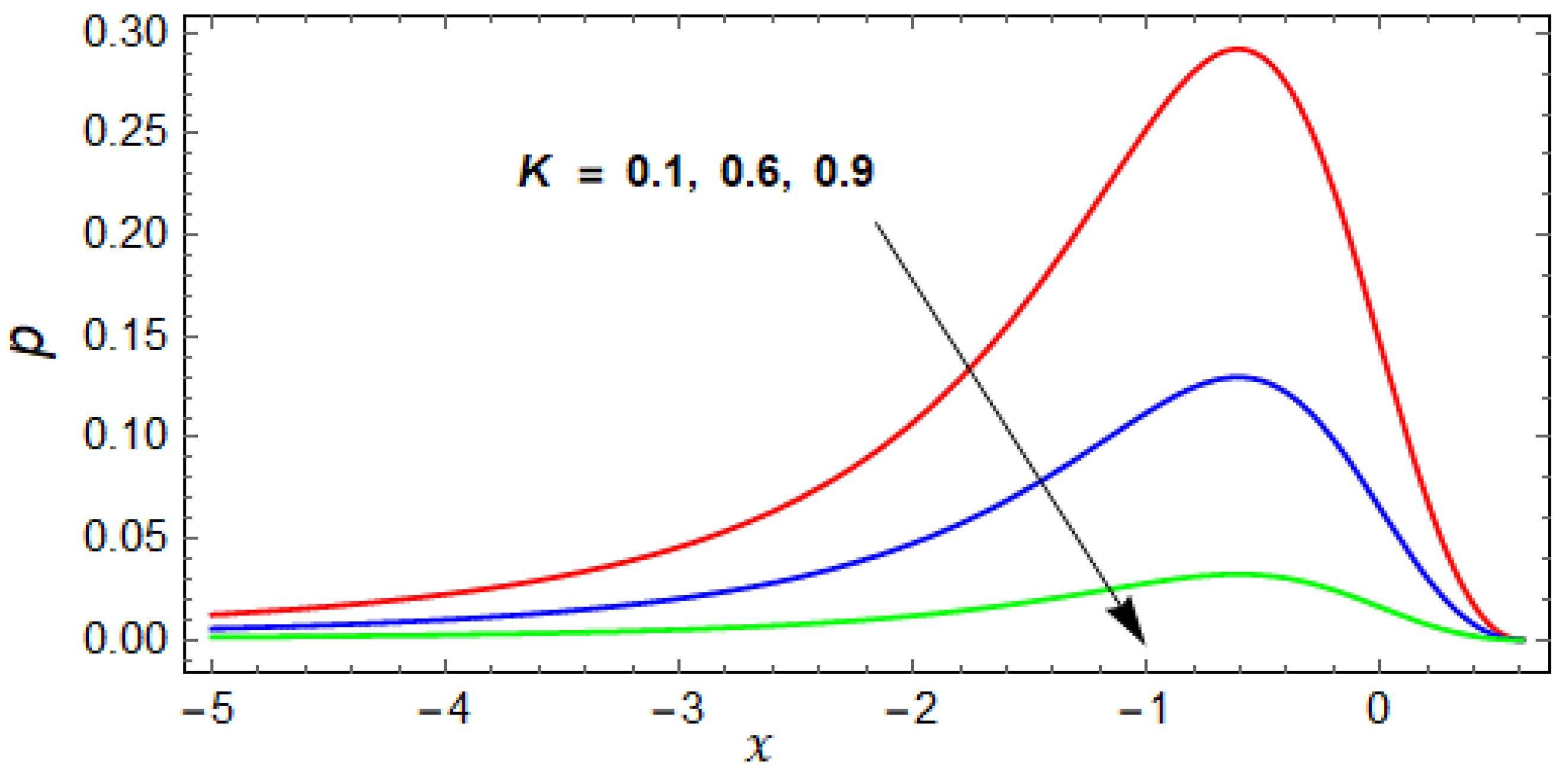
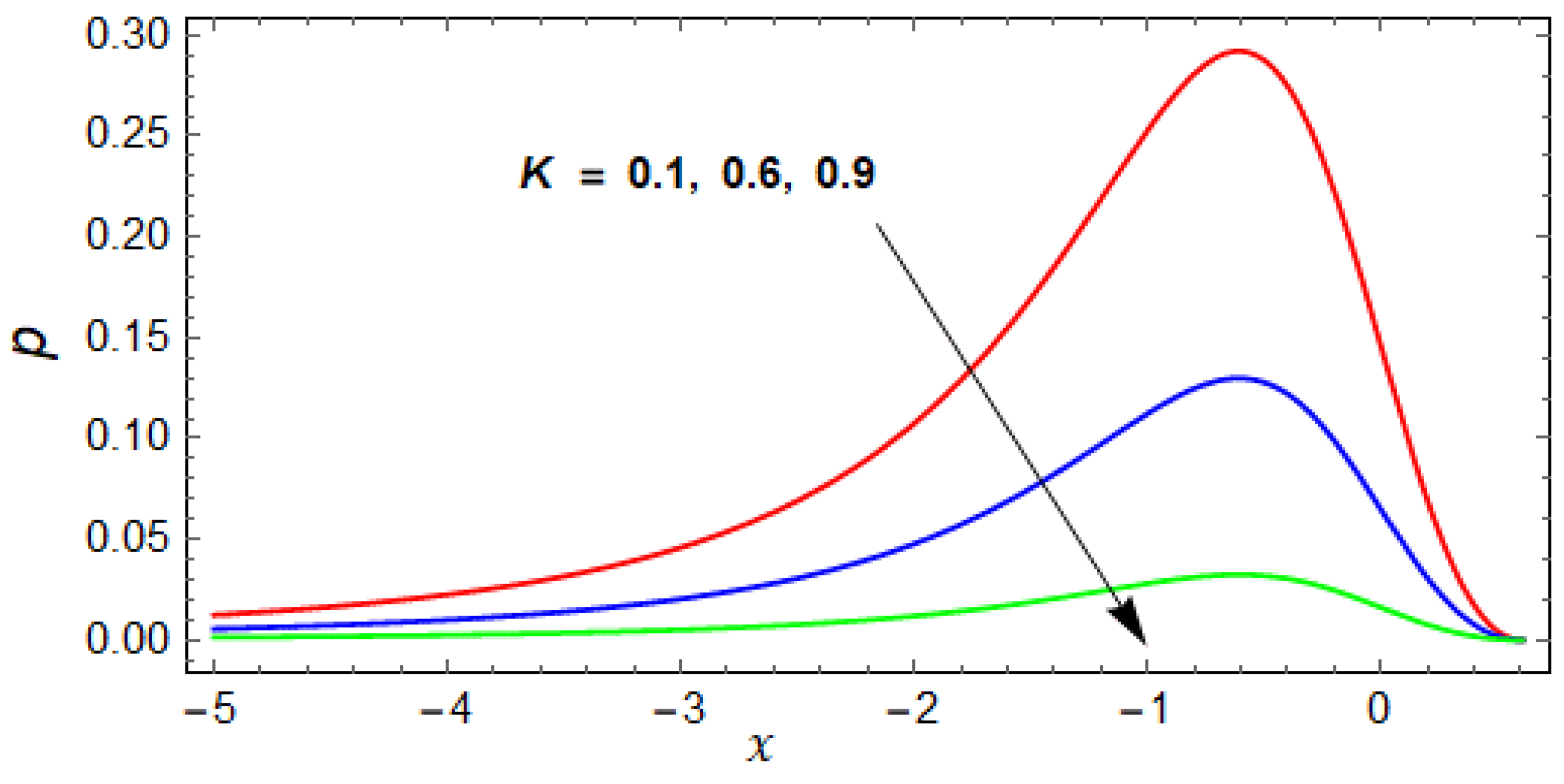
In Figure 2, Figure 3 and Figure 4, the pressure is plotted for the variation of the involved parameters. In Figure 2, the pressure is plotted against x for the variation of couple stress parameter γ . As the γ increases, the pressure starts decreasing, and for γ , the Newtonian curve can be retrieved. The velocity ratio K has the same effects on pressure as of the couple stress fluid parameter, but the impact is greater than γ , see Figure 3.
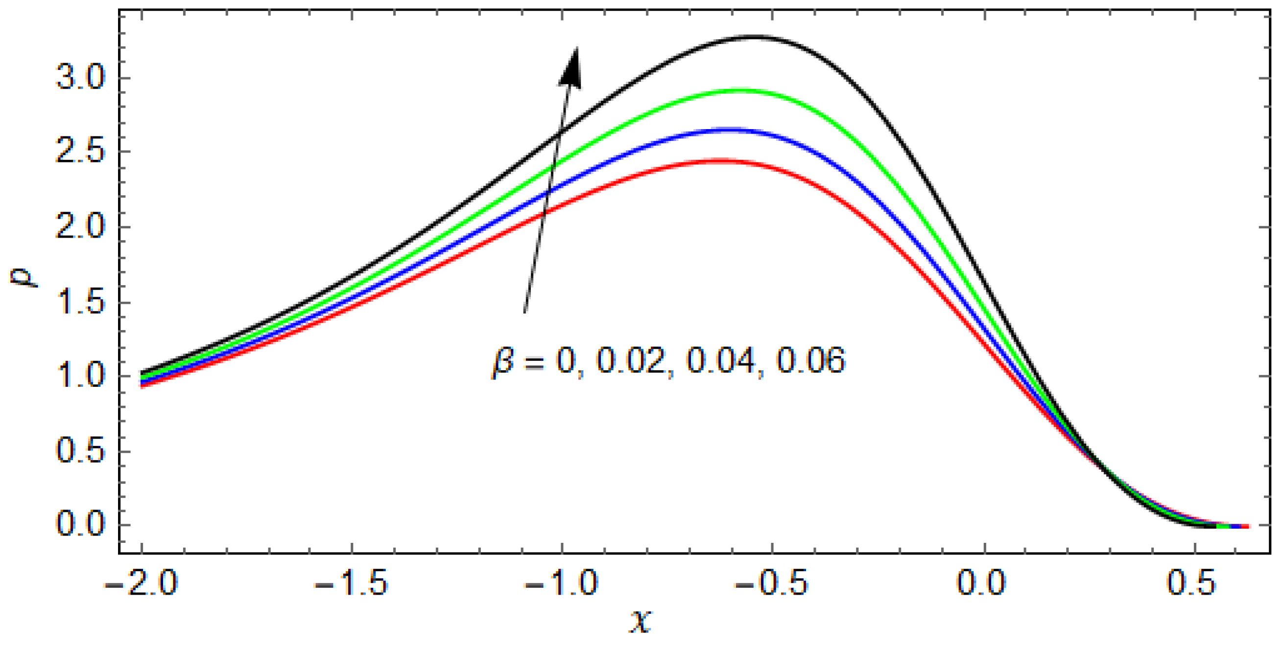
The impact of slip parameter on pressure is plotted in Figure 4. The pressure is minimum when β = 0 , when the values of β increased the pressure increased, as shown in Figure 4.
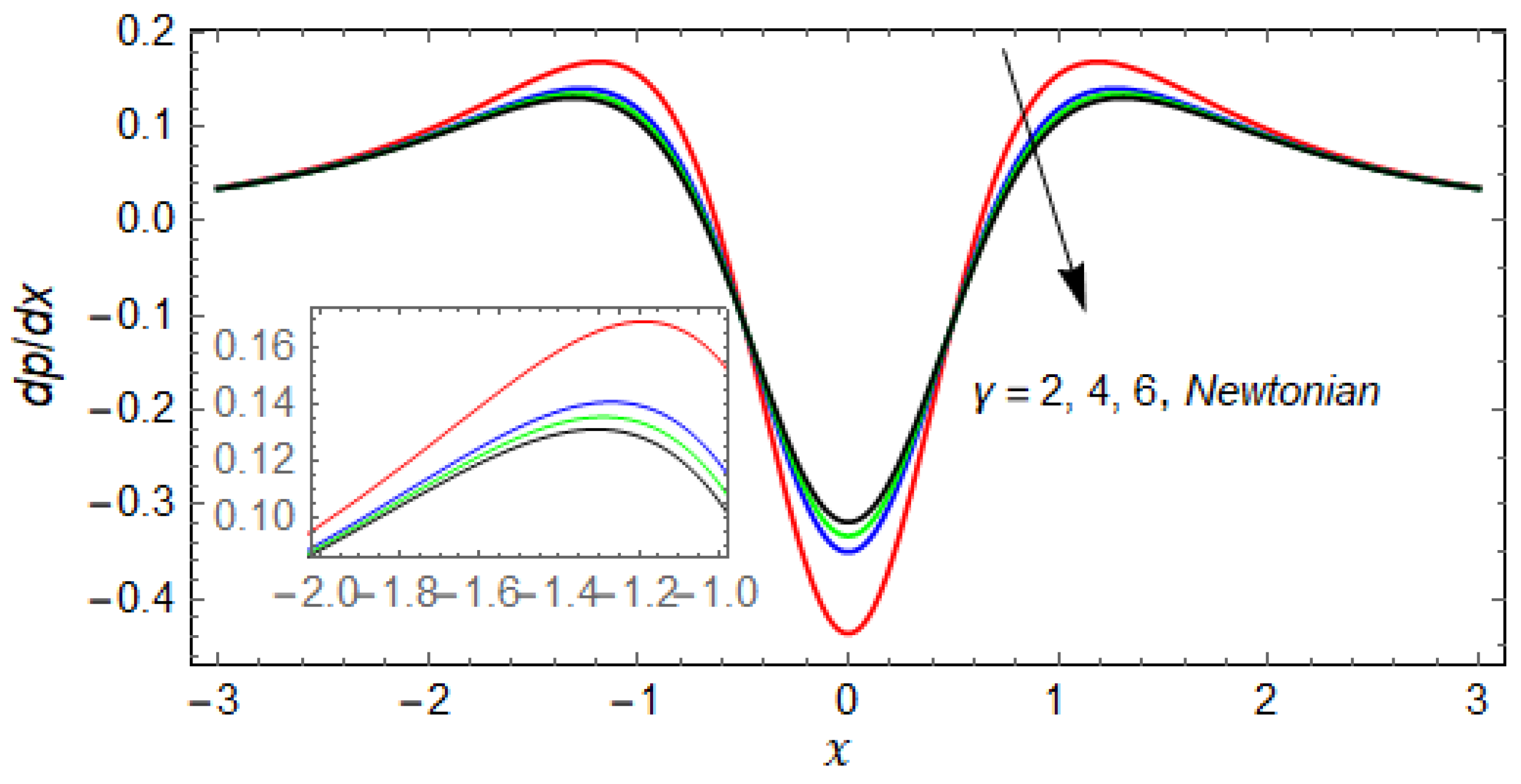
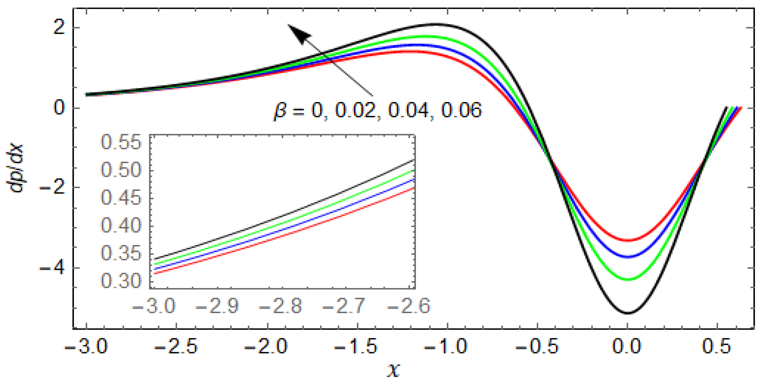
In Figure 5, Figure 6 and Figure 7, the d p / d x is plotted against the axial direction x for the variation of involved parameters. Effects of the couple stress parameter on pressure gradient is plotted in Figure 5. Here the two main regions can be noted, namely the upstream where d p / d x > 0 and downstream region where d p / d x < 0 . From the figure, it can be observed that the pressure gradient decreases as the couple stress parameter increases, while from the point near x = 0.5 to onward, a reverse trend can be seen. The velocity ratio parameter K behaves the same as the couple stress parameter γ , but its impact is much higher than that of γ , see Figure 6. Figure 7 plots the effects of the slip parameter on the pressure gradient. The slip parameter has opposite effects to that of γ and K. In addition, a comparison is made between the slip and no slip effects. It can be seen from Figure 7 that d p / d x is minimum when no slip is present (i.e., at β = 0 ) . However, when the value of β increases, the pressure gradient increases.
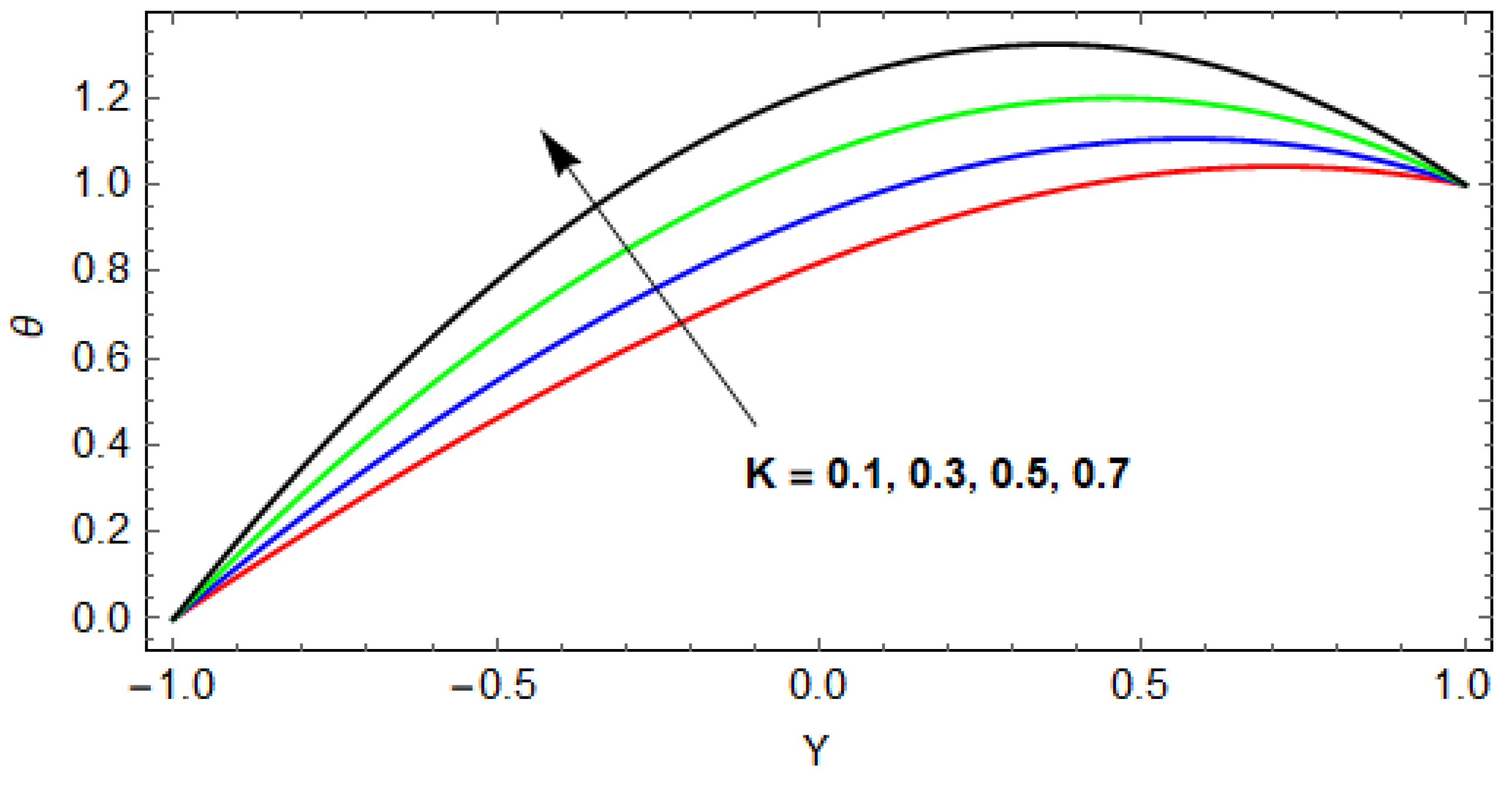
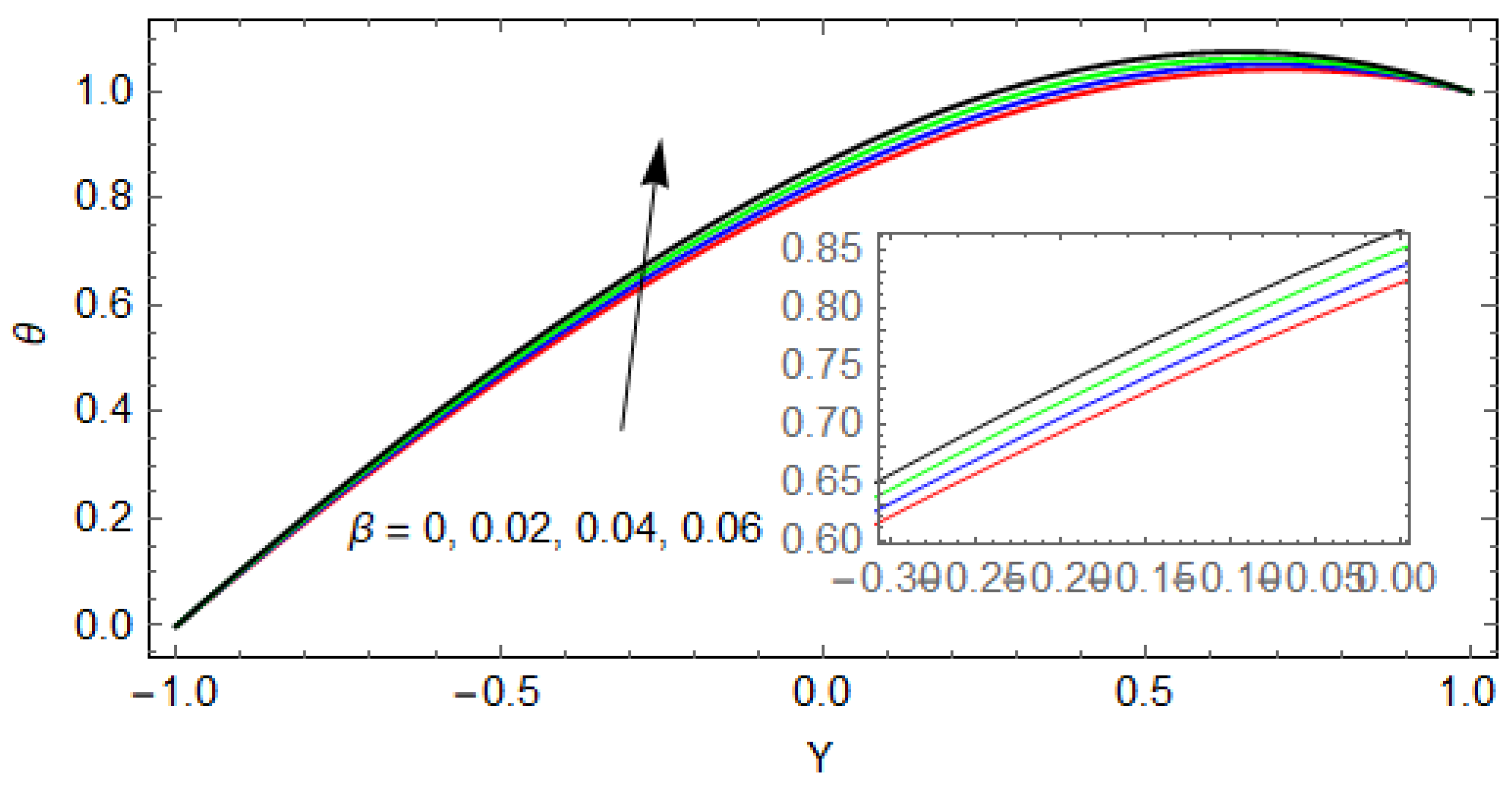
Figure 8, Figure 9 and Figure 10 show how the involved parameter effects the temperature distribution in the reverse roll coating process at B r = 2 . The temperature is zero at the lower roll, when the   Y   increases it starts increasing, and at upper roll its value is maximum. The transformation Y = y / h is used to normalized the temperature equation. In Figure 8, the temperature is plotted along radial direction Y at x = 0.25 ; temperature is a decreasing function of the couple stress parameter. While the variation of K and β has opposite effects on temperature than that of γ , see Figure 9 and Figure 10 respectively.
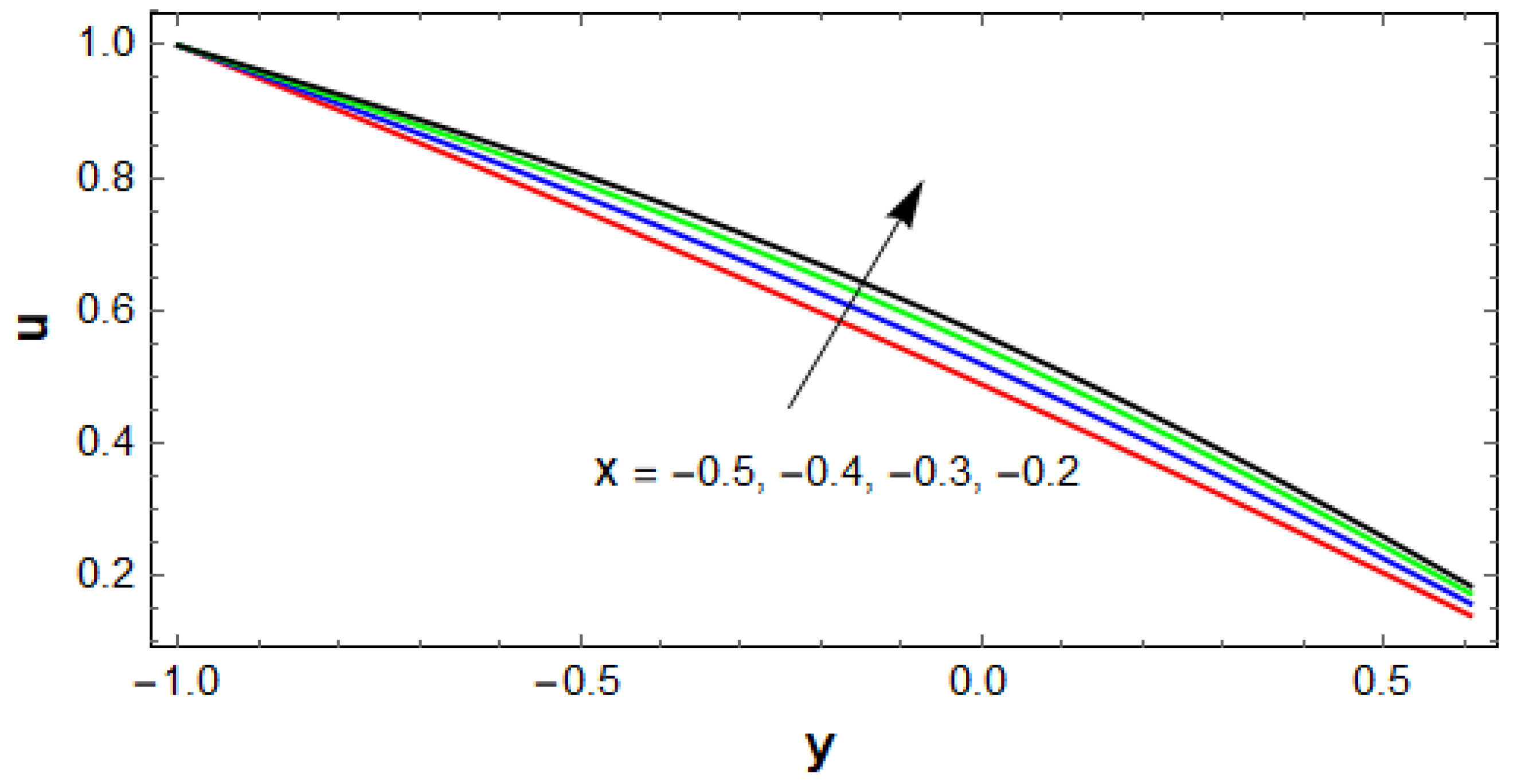
The velocity for different positions of axial direction x is plotted in Figure 11 at K = 0.1, γ = 2 , and β = 0.02 . Velocity increases as the axial position increases.

4. Conclusions

A non-isothermal couple stress fluid is investigated in the reverse roll coating process. A mathematical model is developed and simplified using LAT. The closed form solution for physical parameters like pressure gradient, velocity, and temperature is obtained. While pressure and flow rate is obtained numerically using the root finding algorithm. For large values of the couple stress parameter, the Newtonian results are recovered. The main findings of the study are listed below:
  • The pressure and pressure gradient decreases for increasing values of the couple stress parameter, and for large values of γ the results for the Newtonian case are recovered.
  • The effect of velocity ratio K on pressure is the same as for the couple stress parameter but the impact is greater than γ .
  • The impact of the slip parameter β on the pressure and pressure gradient is opposite to that of K and γ (i.e., the pressure and pressure gradient increase for increasing values of β ) . This is because the fluid moves rapidly along the rollers due to slip and, consequently, the pressure and pressure gradient increase.
  • The temperature profile decreases with increasing values of γ .
  • The variation of the slip parameter and velocity ratio increase the temperature.
  • The flow rate decreases compared to the Newtonian case for the variation of the couple stress parameter γ , which results in decreasing the coating thickness.
  • The flow rate is maximum for the no slip condition and starts increasing when the value of β increases. Hence, the coating thickness is a decreasing function of the slip parameter.
  • At β = 0 , and for γ , the numerical results of flow rate are recovered and matched with Greener and Middleman [20].

Author Contributions

H.S., conceptualization, investigation, writing—original draft, methodology; M.B.H., funding acquisition, writing—review and editing; X.W., supervision; Z.S., Data curation; A.M.A., funding. All authors have read and agreed to the published version of the manuscript.

Funding

This research received no external funding.

Institutional Review Board Statement

Not applicable.

Informed Consent Statement

Not applicable.

Data Availability Statement

Not applicable.

Conflicts of Interest

The authors declare no conflict of interest.

References

  1. Booth, G.L. The Science and Technology of Polymer Films; Sweeting, O., Ed.; Interscience: New York, NY, USA, 1968; Volume 1. [Google Scholar]
  2. Balzarotti, F.; Rosen, M. Systematic study of coating systems with two rotating rolls. Lat. Am. Appl. Res. 2009, 39, 99–104. [Google Scholar]
  3. Zahid, M.; Zafar, M.; Rana, M.A.; Lodhi, M.S.; Awan, A.S.; Ahmad, B. Mathematical analysis of a non-Newtonian polymer in the forward roll coating process. J. Polym. Eng. 2020, 40, 703–712. [Google Scholar] [CrossRef]
  4. Belblidia, F.; Tamaddon-Jahromi, H.R.; Echendu, S.O.S.; Webster, M.F. Reverse roll-coating flow: A computational investigation towards high-speed defect free coating. Mech. Time Depend. Mater. 2013, 17, 557–579. [Google Scholar] [CrossRef]
  5. Zheng, G.; Wachter, F.; Al-Zoubi, A.; Durst, F.; Taemmerich, R.; Stietenroth, M.; Pircher, P. Computations of coating windows for reverse roll coating of liquid films. J. Coat. Technol. Res. 2020, 17, 897–910. [Google Scholar] [CrossRef]
  6. Benkreira, H.; Edwards, M.; Wilkinson, W. A semi-empirical model of the forward roll coating flow of Newtonian fluids. Chem. Eng. Sci. 1981, 36, 423–427. [Google Scholar] [CrossRef]
  7. Hao, Y.; Haber, S. Reverse roll coating flow. Int. J. Numer. Methods Fluids 1999, 30, 635–652. [Google Scholar] [CrossRef]
  8. Greener, J.; Sullivan, T.; Turner, B.; Middleman, S. Ribbing instability of a two-roll coater: Newtonian fluids. Chem. Eng. Commun. 1980, 5, 73–83. [Google Scholar] [CrossRef]
  9. Coyle, D.J.; Macosko, C.W.; Scriven, L.E. Stability of symmetric film-splitting between counter-rotating cylinders. J. Fluid Mech. 1990, 216, 437–458. [Google Scholar] [CrossRef]
  10. Chandio, M.; Webster, M. Numerical study of transient instabilities in reverse-roller coating flows. Int. J. Numer. Methods Heat Fluid Flow 2002, 12, 375–403. [Google Scholar] [CrossRef] [Green Version]
  11. Coyle, D.J.; Macosko, C.W.; Scriven, L.E. The fluid dynamics of reverse roll coating. Aiche J. 1990, 36, 161–174. [Google Scholar] [CrossRef]
  12. Jang, J.Y.; Chen, P.Y. Reverse roll coating flow with non-Newtonian fluids. Commun. Comput. Phys. 2009, 6, 536–552. [Google Scholar]
  13. Greener, Y.; Middleman, S. A theory of roll coating of viscous and viscoelastic fluid. Polym. Eng. Sci. 1975, 15, 1–10. [Google Scholar] [CrossRef]
  14. Middleman, S. Fundamentals of Polymer Processing; McGraw-Hill: New York, NY, USA, 1977; pp. 202–212. [Google Scholar]
  15. Kistler, S.F.; Schweiz, P.M. Liquid Film Coating–Scientific Principles and Their Technological Implications; Springer Science + Business Media: Dordrecht, The Netherlands, 1997. [Google Scholar]
  16. Carvalho, M.S.; Scriven, L.E. Deformable roll coating flows: Steady state and linear perturbation analysis. J. Fluid Mech. 1997, 339, 143–172. [Google Scholar] [CrossRef]
  17. Coyle, D.J.; Macosko, C.W.; Scriven, L.E. Film-splitting flows in forward roll coating. J. Fluid Mech. 1986, 171, 183–207. [Google Scholar] [CrossRef]
  18. Taylor, J.; Zettlemoyer, A. Hypothesis on the mechanism of ink splitting during printing. TappiJ 1958, 12, 749–757. [Google Scholar]
  19. Greener, J.; Middleman, S. Reverse roll coating of viscous and viscoelastic liquids. Ind. Eng. Chem. Fundam. 1981, 20, 63–66. [Google Scholar] [CrossRef]
  20. Sajid, M.; Mughees, M.; Ali, N.; Shahzad, H. Theoretical analysis of blade coating using third grade fluid. J. Plast Film. Sheeting 2019, 35, 218–238. [Google Scholar] [CrossRef]
  21. Sajid, M.; Shahzad, H.; Mughees, M.; Ali, N. Mathematical modeling of slip and magnetohydrodynamics effects in blade coating. J. Plast. Film Sheeting 2019, 35, 9–21. [Google Scholar] [CrossRef]
  22. Shahzad, H.; Wang, X.; Mughees, M.; Sajid, M.; Ali, N. A mathematical analysis for the blade coating process of Oldroyd 4-constant fluid. J. Polym. Eng. 2019, 39, 852–860. [Google Scholar] [CrossRef]
  23. Wang, X.; Shahzad, H.; Chen, Y.; Kanwal, M.; Ullah, Z. Mathematical modelling for flexible blade coater with magnetohydrodynamic and slip effects in blade coating process. J. Plast. Film Sheeting 2020, 36, 38–54. [Google Scholar] [CrossRef]
  24. Kanwal, M.; Wang, X.; Shahzad, H.; Chen, Y.; Chai, H. Blade coating analysis of viscous nanofluid having Cu–water nanoparticles using flexible blade coater. J. Plast. Film Sheeting 2020, 36, 348–367. [Google Scholar] [CrossRef]
  25. Kanwal, M.; Wang, X.; Shahzad, H.; Chen, Y.; Sajid, M. Mathematical modeling of micropolar fluid in blade coating using lubrication theory. SN Appl. Sci. 2020, 2, 1–8. [Google Scholar] [CrossRef] [Green Version]
  26. Kanwal, M.; Wang, X.; Shahzad, H.; Sajid, M.; Yiqi, C. Mathematical modeling of Johnson-Segalman fluid in blade coating process. J. Plast. Film Sheeting 2021, 1–27. [Google Scholar] [CrossRef]
  27. Taylor, G.I. The Scientific Papers of Sir Geoffrey, 1st ed.; Ingram Taylor on Scraping Viscous Fluid from a Plane Surface; Cambridge University Press: Cambridge, UK, 1971; pp. 410–413. [Google Scholar]
  28. Gaskell, P.H.; Summers, J.L.; Thompson, H.M. Creeping flow analyses of free surface cavity flows. Theor. Comput. Fluid Dyn. 1996, 8, 415–433. [Google Scholar] [CrossRef]
  29. Romanò, F.; Türkbay, T.; Kuhlmann, H.C. Lagrangian chaos in steady three-dimensional lid-driven cavity flow. Chaos Interdiscip. J. Nonlinear Sci. 2020, 30, 073121. [Google Scholar] [CrossRef]
  30. Romanò, F.; Suresh, V.; Galie, P.A.; Grotberg, J. Peristaltic flow in the glymphatic system. Sci. Rep. 2020, 10, 1–17. [Google Scholar] [CrossRef]
  31. Wahba, E. Multiplicity of states for two-sided and four-sided lid driven cavity flows. Comput. Fluids 2009, 38, 247–253. [Google Scholar] [CrossRef]
  32. Romanò, F.; Albensoeder, S.; Kuhlmann, H.C. Topology of three-dimensional steady cellular flow in a two-sided anti-parallel lid-driven cavity. J. Fluid Mech. 2017, 826, 302–334. [Google Scholar] [CrossRef]
  33. Stokes, V.K. Couple stresses in fluids. Phys. Fluids 1966, 9, 1709. [Google Scholar] [CrossRef]
  34. Sarangi, M.; Majumdar, B.C.; Sekhar, A.S. Elastohydrodynamically lubricated ball bearings with couple-stress fluids, Part I: Steady-state analysis. Tribol. Trans. 2005, 48, 404–414. [Google Scholar] [CrossRef]
  35. Saini, P.K.; Kumar, P.; Tondon, P. Thermal elastohydrodynamic lubrication characteristics of couple stress fluids in roll-ing/sliding line contacts. J. Eng. Tribol. 2007, 221, 141–153. [Google Scholar]
  36. Ali, N.; Sajid, M.; Abbas, Z.; Bég, O. Swimming of micro-organism in a fluid with couple stresses—A rheological model of em-bryological hydrodynamic propulsion. J. Mech. Med. Biol. 2017, 3, 1750054. [Google Scholar] [CrossRef]
  37. Javed, M.A.; Ali, N.; Sajid, M. Analysis of couple stress fluid in helical screw rheometer. IJST 2015, 39A4, 551–558. [Google Scholar]
  38. Mughees, M.; Sajid, M.; Ali, N.; Shahzad, H. Nonisothermal analysis of a couple stress fluid in blade coating process. Polym. Eng. Sci. 2020, 60, 1129–1137. [Google Scholar] [CrossRef]
  39. Ali, N.; Javed, M.A.; Atif, H.M. Non-isothermal analysis of calendering using couple stress fluid. J. Plast. Film Sheeting 2018, 34, 358–381. [Google Scholar] [CrossRef]
  40. Ali, N.; Atif, H.M.; Javed, M.A.; Sajid, M. A theoretical analysis of roll-over-web coating of couple stress fluid. J. Plast. Film Sheeting 2018, 34, 43–59. [Google Scholar] [CrossRef] [Green Version]
  41. Ali, F.; Hou, Y.; Zahid, M.; Rana, M.A. Theoretical study of the reverse roll coating of non-isothermal magnetohydrodynamics viscoplastic fluid. Coatings 2020, 10, 940. [Google Scholar] [CrossRef]
  42. Ali, F.; Hou, Y.; Zahid, M.; Rana, M. Mathematical analysis of pseudoplastic polymers during reverse roll-coating. Polymers 2020, 12, 2285. [Google Scholar] [CrossRef]
Figure 1. Geometric representation of reverse roll coating. (a) working principle (b) Schematic diagram.
Coatings 11 01249 g001
Figure 2. Pressure distribution against x for variation of γ .
Coatings 11 01249 g002
Figure 3. Pressure distribution against x for variation of velocity ratio K .
Coatings 11 01249 g003
Figure 4. Pressure distribution against x for variation of β .
Coatings 11 01249 g004
Figure 5. Pressure gradient   d p / d x versus x for variation of γ .
Coatings 11 01249 g005
Figure 6. Pressure gradient d p / d x versus x for variation of velocity ratio K.
Coatings 11 01249 g006
Figure 7. Pressure gradient d p / d x versus x for variation of β .
Coatings 11 01249 g007
Figure 8. Temperature distribution versus Y for variation of γ.
Coatings 11 01249 g008
Figure 9. Temperature distribution versus Y for variation of K.
Coatings 11 01249 g009
Figure 10. Temperature distribution against Y for the variation of β.
Coatings 11 01249 g010
Figure 11. Velocity profile for the variation of x.
Coatings 11 01249 g011
Table 1. Effects of the couple stress parameter γ on flow rate, transition point, and thickness β = 0, x = 2.
γ λ ζ t C t
10.5143360.5347322.15734
20.5331520.6079192.23261
30.5414630.6375762.26585
40.5453220.6508872.28129
Newtonian0.5515850.6719312.30654
Table 2. Effects of the couple stress parameter γ on flow rate, transition point, and thickness at β = 0.02 ,   χ = 2 .
γ λ ζ t C t
10.5084740.5102232.13429
20.5300000.5962842.22000
30.5388690.6284682.25547
40.5429390.6426982.27175
50.5450730.6500372.28029
Table 3. Effects of the slip parameter β on flow rate transition point and thickness at γ = 2 = χ .
β λ ζ t C t
00.5331520.6079192.23261
0.010.5316080.6022462.22643
0.020.5300000.5962842.22000
0.040.5264700.5833632.20628
0.060.5228070.5688452.19123
0.080.5186300.5522882.17452
Publisher’s Note: MDPI stays neutral with regard to jurisdictional claims in published maps and institutional affiliations.