Abstract
The aim of the article was to identify the effect of material hardness on the tribocorrosion process by comparing two material solutions. The analysis concerned the assessment of the process intensity and the identification of the mechanisms responsible for material loss. Possible mechanisms of tribocorrosion common for materials of high hardness were determined. Two classic material solutions (based on AISI 1045 steel) ensuring high hardness of the subsurface layers were tested: nitriding with an additional oxidation and impregnation process, and Physical Vapour Deposition (PVD) coating. In order to better identify the impact of hardness on the tribocorrosion process in each individual test, the pressures in the contact zone were increased. The tribocorrosion tests were carried out in 3.5% NaCl with free corrosion potential (OCP) for the ball-on-plate system. The results of the tribocorrosion tests presented in the article indicate that the synergy effect of friction and corrosion can be generated by the same mechanisms of material removal in both the material solutions tested. The intensity of these mechanisms is determined by material hardness. The likely mechanism of generating the synergy effect may be related to the formation of local pits along the friction path. The corrosion processes that are initiated by the cracking of the hard surface layer create local cavities, which most probably intensify frictional wear in successive time intervals. The area around the cavities facilitates plastic deformation, the initiation of cracking of the cyclically deformed layer and the tearing of larger pieces of material (especially at higher unit pressures in the frictional contact zone).
1. Introduction
Many sliding nodes in devices operating in a seawater environment (e.g., on oil rigs) are exposed to damage caused by tribocorrosion. The loss of material caused by the combined impact of friction and corrosion can be a significant operational problem. One way to eliminate this problem and to extend the durability of the equipment is the use of high hardness materials. High hardness of the surface layer ensures adequate resistance to mechanical stress as well as friction damage. The higher durability of the surface layer should also reduce the material loss caused by the corrosive nature of seawater. The most intense corrosive interactions resulting from mechanical forces are initiated on the freshly exposed surface of the material.
In the article, two classic material solutions (based on AISI 1045 steel) ensuring high hardness of the subsurface layers were selected for an analysis of the tribocorrosion process: nitriding with an additional oxidation and impregnation process, and the application of a physical vapour deposition (PVD) coating. The selected materials are the result of a search for solutions to be used for elements operating at high pressures in the seawater environment (e.g., actuator pistons on drilling platforms). Classical material solutions were selected because the purpose of the research analyses was an attempt to identify some common features of the tribocorrosion process in the group of materials with high hardness.
Material hardness may be a major factor in tribocorrosion. Many analytical models used to predict tribocorrosion use material hardness as a determinant of the intensity of material loss [1,2]. Material hardness has both mechanical and corrosion-related effects. Material loss caused by friction occurs at the points of actual contact and to a smaller material loss caused by friction. The corrosive processes are initiated on a surface previously exposed by mechanical separation of the material [3,4]. The material hardness therefore affects the intensity of the electromechanical impact as well. The higher the hardness, the higher the resistance of the material to wear caused by friction. However, this does not always mean higher resistance to tribocorrosion [5]. It is often the case that a technological process used to make a material harder will reduce the resistance of the material to corrosion.
Physical vapour deposition (PVD) coatings are widely used on many machine parts and tools to produce surface with anticorrosion and antiwear properties [6,7,8,9,10,11,12]. The coating lifetime depends not only on the properties of the base material from which they are produced, but also on the substrate surface properties. Therefore, the benefits of using modern PVD coatings are undisputed. By increasing the hardness of their surfaces and their resistance to corrosion, the parts of machines and tools covered with PVD coatings show lower wear, good adhesion and high hardness [13].
The CrN layer produced by using the PVD method has a better corrosion resistance than the TiN/TiAlN layers. Researchers [14] have found that the corrosion resistance in a 3% NaCl solution of AISI 304 steel coated with TiN, TiAlN and CrN is the highest for CrN coating, and the lowest for TiN. Su et al. [15] compared CrN and TiN layers fabricated by using the PVD method on tools and parts of machines and found a significantly higher resistance to wear due to friction on CrN coatings in comparison to TiN coatings.
The CrN coating is quite frequently used as protection against mechanical and corrosive wear in the manufacture of machine parts (especially sliding nodes) and tools. One of the more commonly used methods of applying CrN coatings is the PVD method. Recently, tribocorrosion tests of CrN coatings created by using the PVD method in the chloride ion environment have been carried out. The tribocorrosion performance shows significant resistance to wear and corrosion [16,17,18,19].
The production of duplex and hybrid layers in combined heat and chemical treatments with PVD methods is currently widely used. As has been mentioned above, the synergy effect of the hybrid layer, resulting from the combination of two individual processes makes it possible to obtain excellent performance that would otherwise be impossible to achieve in separate processes [20]. Individual component layers of the tested hybrid Cr/CrN coating were fabricated using the PVD method. Bayon et al. [21] investigated this type of hybrid coating. The research examined the tribocorrosion behavior of multilayer coatings with different structures by instantaneous deviations measurements of standard potential under friction conditions. Tribocorrosion tests were performed in a chloride ions environment. The studies found that the wear rate has a significant effect on the tribocorrosion performance and that the tribocorrosion wear occurs as a result of the damage and removal of the surface layer and the substrate material exposure to the corrosive medium.
The excellent resistance to mechanical wear and very good corrosion resistance of hybrid Cr/CrN coatings were confirmed in subsequent studies [6,22]. The hybrid layers, manufactured by using the PVD process, widely used to increase the anticorrosive and mechanical properties of the surfaces of machines and tools, present a synergy effect [13,20]. The tests confirm the excellent resistance to mechanical wear and corrosion of a hybrid coating Cr/CrN in a chlorine environment [6,21,23].
In addition, a controlled gas nitriding process with subsequent oxidation and an impregnation process increases the tribocorrosion performance of material in a 3.5% NaCl environment [24]. This might be used for many parts of machines and equipment exposed to tribocorrosion wear [25].
The article presents an assessment of resistance to tribocorrosion for selected materials of high hardness in a seawater environment. The tribocorrosion process was comparatively analyzed for two material solutions of different hardness rates at increasing pressures. In individual tests, the mechanical forces were differentiated in order to better identify the impact of hardness on the process of material removal.
The main goals of the research are as follows:
- A comparative assessment of resistance to tribocorrosion in 3.5% NaCl of the analyzed material solutions;
- The identification and quantitative evaluation of the synergy of friction and corrosion in the total material loss;
- The identification of the probable mechanism of the friction–corrosion synergy effect under tribocorrosion conditions.
The authors of this article assume that it is possible to identify a likely shared mechanism creating a synergy of friction and corrosion for high-hardness materials. However, the analysis is based on two different material solutions only.
2. Materials and Methods
2.1. Coatings and Identification Methods
The gas nitrided with subsequent oxidation and impregnation and the Cr/CrN hybrid coatings were formed on samples made from medium carbon steel AISI 1045 containing 0.45% C, 0.65% Mn and 0.25% Si. The formation process of the Cr/CrN coating was carried out by means of the arc-evaporation method (Arc-PVD). The device (Metaplas Ionon, Radom, Poland) was equipped with three arc sources, a substrate polarization system, the substrate temperature and operating gases monitoring systems. Pure chromium cathodes were used as the source of arc for the formation of Cr/CrN hybrid coatings. Disk-shaped samples of substrate sheets 10 mm in diameter and 6 mm thick were selected for the tests. The samples were mechanically polished to obtain a roughness parameter Ra = 0.03 µm before the coating deposition process was initiated. Before the samples were placed in the device chamber and the hybrid surface treatment was carried out, a chemical washing process in an ultrasonic cleaner had been applied. They were skimmed at UMO-50-100 station (Radom, Poland) by using TRI and ethyl alcohol and dried thoroughly, according to the parameters given in Table 1.

Table 1.
The cleaning process parameters of AISI 1045 samples made in ultrasonic cleaner.
Prior to the start of each process, the samples had been preheated in a vacuum chamber using resistance heaters. The preheating temperature was approx. 300 °C with a pressure of 5.0 × 10⁻⁵ mbar. The process of deposition of the Cr/CrN hybrid coating was launched by the deposition of a thin coating of chromium with a thickness below 1 µm. Then, a chromium nitride coating was produced. Table 2 summarizes the technological parameters of the Cr/CrN coating build-up process.
Table 2.
Parameters of Cr/CrN metallic coating deposition process.
Samples made of AISI 1045 steel were subjected to a preliminary heat treatment before gas nitriding process to improve the properties. Firstly, the samples were hardened at 860 °C for 0.5 h. Secondly, the samples were tempered at 480 °C for 2 h. Then the samples were subjected to controlled gas nitriding at 570 °C, for 5 h in a 100% dissociated ammonia atmosphere with a 2.5 nitrogen potential. After the gas nitriding process, the compound layer was subjected to oxidation. This process was carried out in a steam atmosphere at the temperature of 550 °C. The resulting oxide layer was impregnated with BS 45 as a corrosion inhibitor. The surface zone of the gas nitrided coating is porous. In order to ensure better corrosion resistance, this coating is impregnated with corrosion inhibitor. The thin protective oxide layer formed on the surface of gas nitrided coating ensures the tightness of porous.
The structure and surface morphology of the coatings were analyzed through microscopic observations performed using a Hitachi TM-3000 scanning electron microscope (Radom, Poland) with a BSE detector and Tescan Mira3 (Poznan, Poland). The structure was investigated using polished metallographic cross-sections of steel samples with coatings. The X-ray phase analysis used a Bruker D8 diffractometer (Plock, Poland) with CuKα X-rays (λ = 0.1541837 mÅ).
Surface engineering is the process where the design of surface and substrate systems is defined so as to enhance their properties and achieve performance that could not be achieved either by the surface composition or by the substrate itself. According to the rules for taking hardness measurements with the use of penetration methods, plastic deformation caused by the penetrator should occur only in the tested material area. Based on this assumption, both hardness and Young modulus measurement of PVD coating was determined by using NanoHardness Tester (Radom, Poland) equipped with the Berkovich indenter and an optical microscope (Radom, Poland). The device allows for load setting within the 0.05 and 500 mN and enables precise selection of the indenter penetration depth in the tested material in the range up to 1000 µm. The following parameters were used in the measurements: F = 10 mN, dF/dt = 60 mN/min. The gas nitrided coating hardness measurement was carried out on metallographic sections perpendicular to the surface of the samples. The Neophot 2 light microscope (Plock, Poland) with the Hanemann attachment under the load of 20 g (HV0.02) was used to prepare tests in accordance with the Vickers method based on the EN ISO 6507-1 code [26]. The metallographic sections were also used for the thickness measurements of the tested coatings.
The indentation method is a destructive penetration method. The adhesion test based on this method consists of the Rockwell indenter pressing perpendicularly into the tested coating with a constant acting force on the indenter. Microscopic observations were used to assess the form and intensity of the coating damage in the penetration area. The indentation method was a comparative evaluation. The adhesion assessment was carried out by classifying forms of destruction into six categories [27]. The adhesion test was carried out using a Revetest tester (Radom, Poland) equipped with a Rockwell indenter and an optical microscope (Radom, Poland).
2.2. Tribocorrosion Tests and Wear
The tests of the tribocorrosion process were carried out for a model ball-on-plate sliding matching in an electrolytic environment. The test samples were mounted in a special PVC chamber holding a corrosive environment of 3.5% NaCl. The counter-face was an undeformed pin equipped with an Al2O3 alumina ball, which slides in a rotary way back and forth on the sample.
The potentiostat ATLAS 9833 (Atlas-Sollich, Poznan, Poland) with three electrode configuration was used to monitor the potential in the friction pair. A standard calomel electrode (SCE) was used as a reference electrode. Its potential versus standard hydrogen electrode was 244 mV. A platinum wire was used as the counter electrode (CE). The specimen operated as the working electrode (WE). Once each test was finished, profilometric measurements of the depth trace of wear were taken in the mid-distance of the friction path. A detailed description of the presented tribocorrosion test methodology was published in previous articles [28,29] and this methodology was designed and executed according to the concept presented by Mischler and Jemmely in their work [30,31].
During each test the ball slid over a track length of 6 mm with the frequency of 2 Hz for the period of about 60 min. All the experiments involved the use of Al2O3 alumina balls with the diameter of 7.0 mm. The tests were carried out at the following loads: 9, 13, and 19 N. The smallest load corresponds to the maximum initial Hertz contact stress of about 1.4 GPa. The main tribocorrosion tests were performed at the open circuit potential (OCP). In order to identify the tribocorrosion components, tests were also performed under the conditions of cathodic polarization (−900 mV vs. SCE) at the load of 13 N.
3. Results
3.1. Characterisation of the Coatings
It can be concluded from Figure 1 that in the hybrid layer composed of Cr and CrN there occur CrN phases with a regularly centered grid and Cr2N with a hexagonal grid. The examination also shows the presence of chromium and iron phases.
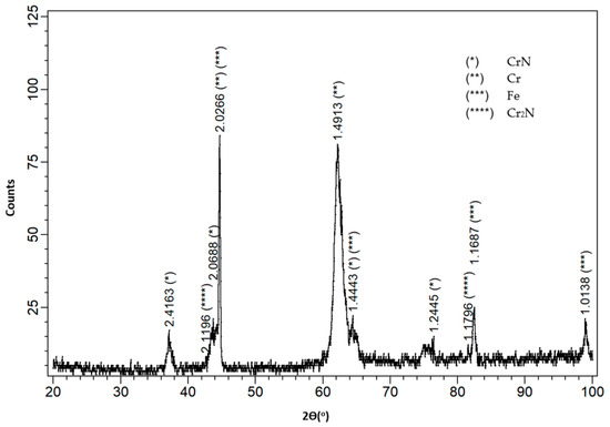
Figure 1.
XRD pattern of Cr/CrN coating produced by means of the physical vapor deposition (PVD) method on AISI 1045 steel.
The surface of the Cr/CrN PVD coating at 500× magnification is shown in Figure 2. An analysis of the surface morphology of the obtained hybrid coating has shown a homogeneous structure with a small number of droplets. The tested thickness of hybrid coating was 4.7 μm. However, a thin coating of Cr was approximately 1 µm and thickness of CrN was about 3.7 µm.
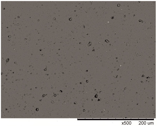
Figure 2.
An image of the hybrid layer produced using a scanning electron microscope, consisting of Cr layer and CrN, produced on AISI 1045 medium carbon steel.
A microstructure investigation of the coatings produced on the surface of AISI 1045 steel was also carried out, and it is shown in Figure 3. The gas nitride coating with subsequent oxidation was disclosed by means of nital etching of metallographic cuts. The total thickness of the coating was about 27 µm. However, the thickness of the oxide layer was about 6 µm and the thickness of the nitrided gas only was about 21 µm. The microstructure of the Cr/CrN coating was obtained on polished metallographic cross-sections. The dark grey coating of about 5 µm thickness adheres uniformly to the substrate steel.
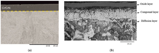
Figure 3.
The microstructure of the tested coatings produced on AISI 1045 steel (a) Cr/CrN PVD, (b) gas nitrided with subsequent oxidation and impregnation.
The measurements of hardness and Young’s modulus of the Cr/CrN hybrid coating were carried out while maintaining the maximum indenter penetration lower than 10% of the coating thickness. The measurement results are shown in Table 3.
Table 3.
The measurement results of hardness.
The analysis of the results of hardness measurements showed that the tested Cr/CrN PVD coating is characterized by a higher hardness than the gas nitrided coating. The Young’s modulus of the Cr/CrN hybrid coating is 337 GPa. The hardness and the Young’s modulus of the samples made from AISI 1045 steel are 235 HV and 202 GPa, respectively [22]. The images shown in Figure 4 make it possible to estimate the coating adhesion with the use of the indentation method.
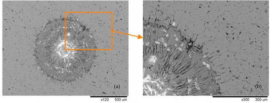
Figure 4.
The adhesion results by using the indentation method of Cr/CrN coating. (a) contact zone; (b) edge of contact zone.
According to the destruction classification forms presented in [24], the adhesion assessment may be assigned to grade HF2. It indicates good Cr/CrN coating adhesion to the AISI 1045 carbon steel substrate.
3.2. Corrosion Resistance
Figure 5 shows the polarization curves of the tested coatings—Cr/CrN PVD and gas nitrided with subsequent oxidation and impregnation. The polarization curves were utilized to indicate the corrosion potential and the corrosion current density. The corrosion potential of the gas nitrided coating with subsequent oxidation and impregnation is Ecorr = −468 mV and Ecorr = −553 mV for the Cr/CrN PVD coating, while the corrosion current density, icorr, is 4 and 0.5 µA/cm2, respectively.
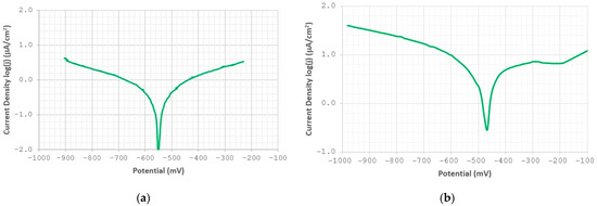
Figure 5.
Polarization curves of the tested coatings: (a) Cr/CrN PVD, (b) gas nitrided with subsequent oxidation and impregnation.
The factor which largely determines the coating’s resistance to the impact of the corrosive environment is its thickness. In this case, after oxidation and impregnation the thickness of the nitrided coating is about 27 μm and is four times greater than the thickness of the Cr/CrN PVD coating, which is about 5 μm.
3.3. Tribocorrosion Performance
The main results of the tribocorrosion tests—performed at an open circuit potential (OCP)—are shown in Table 4 and Table 5. Table 4 shows the depth of the wear trace as an evaluation of material loss during the tribocorrosion test. On the other hand, Table 5 presents material loss expressed as the volume of the wear trace, which will allow for the selection of tribocorrosion components in the next part of this article. The tables show the mean values for the test series and the standard deviation. At least three tribocorrosion tests were performed for each load value. Figure 6 shows the tribocorrosion wear trace of the tested coatings. The results show that tribocorrosion wear occurred only in the tested zone.
Table 4.
Tribocorrosion wear of investigated materials related to different acting forces on the basis of the wear trace.
Table 5.
Tribocorrosion wear of investigated materials related to different acting forces on the basis of the volume wear.
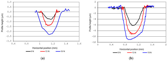
Figure 6.
Profile shapes of the wear trace of the investigated coatings after tribocorrosion tests at an open circuit potential, EOCP: (a) Cr/CrN PVD, (b) gas nitrided with subsequent oxidation and impregnation.
The tribocorrosion test results of the Cr/CrN PVD coating provided under the load of 9 N show the depth of the wear trace of about 1 µm. However, under the load of 19 N, it was approximately 2 µm. These values for the gas nitrided coating are approx. 6 and 12 µm, respectively. The smallest tribocorrosion wear volume in the case of AISI 1045 steel with the gas nitrided coating is 0.011 mm3, and it corresponds to the 9 N load, whereas the largest wear volume—0.027 mm3—corresponds to the force of 19 N. In the case of Cr/CrN PVD coating, the material loss increases when the loads in the contact zone are enhanced. The tribocorrosion wear volume varies from 0.00064 to 0.00203 mm3 related to the changes of the acting force. All the presented results clearly show that the material loss in the case of Cr/CrN PVD coating is lower than in the case of the gas nitrided one with subsequent oxidation and impregnation coating in the chloride ions environment.
Apart from assessing the tribocorrosion resistance of the tested materials, the synergy effect between friction and corrosion in the tested process was also identified quantitatively. The research tests and computational analyses were carried out for the loading force of 13 N. The total material loss during tribocorrosion (T) is the sum of only mechanical wear (W0), only corrosion wear (C0), and the synergy effect of wear and corrosion (S) [32]:
T = W0 + C0 + S
The pure mechanical wear was estimated on the basis of the test with cathodic potential polarization in 3.5% NaCl environment (approx. 900 mV vs. SCE). Exemplary wear profiles obtained for the cathodic polarization are shown in Figure 7. The mere corrosive wear (C0) was calculated on the basis of the corrosion current density by using the Faraday equation (Table 6). In the total tribocorrosion wear of both tested materials, the mechanical wear and the corrosion synergy effect can be observed. It is above 30%.
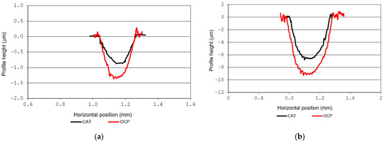
Figure 7.
Profiles shape comparison of the wear traces of the investigated coatings after tribocorrosion tests at an open circuit potential and cathodic potential: (a) Cr/CrN PVD, (b) gas nitrided with subsequent oxidation and impregnation.
Table 6.
An analysis of tribocorrosion wear components under the load of 13 N.
Figure 8 presents the potential changes during the tribocorrosion tests under the load of 19 N. Both tested coatings present similar potential characteristics, showing passivation capability. This is demonstrated by the decrease in the potential when the test was initiated with a ball movement. The ball displacement removes the passive layers on the sample surface. When the ball stops and the wear process is completed, the potential increases. A passive oxide layer occurs again on the wear trace surface.
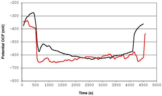
Figure 8.
Time evolution of the potential during the tribocorrosion test for the tested coatings at an open circuit potential, EOCP: Cr/CrN PVD (the red line) and gas nitrided with subsequent oxidation and impregnation (the black line).
4. Discussion
The first of the highlighted goals of the presented study was a comparative analysis of tribocorrosion of the Cr/CrN PVD and gas nitrided coatings produced on AISI 1045 medium carbon steel in 3.5% NaCl. The full range of all applied loads shows that the PVD coating presents lower tribocorrosion wear than the gas nitrided one. The better resistance to corrosion activity of 3.5% NaCl and a higher hardness of the PVD coating can be considered as the main causes of this state.
The actual contact zone in the friction node is smaller for the Cr/CrN PVD coating. Consequently, the separated material comes from a smaller area due to frictional interactions. It correlates directly to the intensity of tribocorrosion wear. The tribocorrosion processes are generally initiated on the surface that is exposed by mechanical removal of the material. In the case of the harder PVD coating, tribocorrosion processes occur on a smaller area and are not as intense as in the case of the gas nitrided coating (Figure 5).
For both analyzed material solutions, in the quantitative assessment (Table 6), a clear synergy effect of friction and corrosion was found. Despite the clear difference in the total tribocorrosion wear (Table 4 and Table 5), the synergy effect for both materials is very similar (ca. 30%). It can be concluded that (perhaps) in both cases the tribocorrosion process occurs due to the same elementary wear mechanisms intensified by the unit pressure in the frictional contact zone.
In order to verify this assumption, the elementary mechanisms of tribocorrosion were identified by observing the wear to the surface. Figure 9 and Figure 10 show traces of wear on the tested coatings under various loads in the friction contact zone. The images depict the diversity of the wear mechanisms (their type and intensity). It can also be seen that the pressure in the contact zone affects the tribocorrosion process.
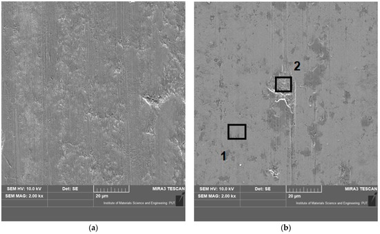
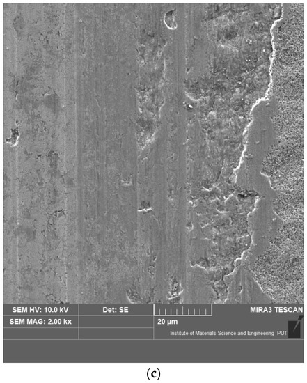
Figure 9.
Pictures of the wear trace surface for the gas nitrided coating at an open circuit potential, EOCP, under specific loads: (a) 9 N, (b) 13 N, (c) 19 N.
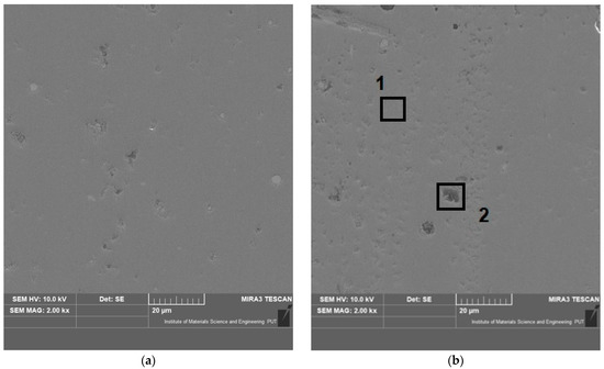
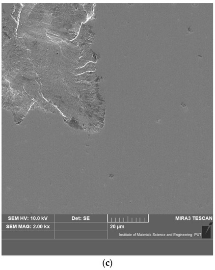
Figure 10.
Pictures of the wear trace surface for Cr/CrN PVD coating at an open circuit potential, EOCP, under specific loads: (a) 9 N, (b) 13 N, (c) 19 N.
For the lowest load value in the contact zone the abrasive wear prevails in the case of the gas nitrided coating. (Figure 9a). The parallel grooves are noticeable on the surface of the wear trace that correspond to the movement direction of the counter-sample. When the tests were completed under the load of 13 N, local cavities along the friction path occurred (Figure 9b—area 2). These are most likely due to the corrosive nature of the environment in places where the material separation (a phenomenon of local nature) had previously occurred as a result of friction. Such a mechanical separation of the material can also result from cracking of the hard surface layer. The area of the local cavity was analyzed in terms of its chemical composition. The obtained result differs from the chemical composition of the tested material in the area of a uniform material loss. The sites where the chemical composition was analyzed are marked in Figure 9b. The results of the analysis are presented in Figure 11. The difference (a lower nitrogen content) may indicate a large depth of the defect. A local cavity can create a synergy of friction and corrosion in the total tribocorrosion wear. Under the cyclic conditions, crack initiation may occur as a result of fatigue processes leading to the separation of larger material part around cavities (pits). These forms of wear are indicated following the test under the highest load value (Figure 9c). The numerous material detachments along the friction path may also be a result of plastic deformation. The implemented force of 19 N during the test facilitates the described material damage, especially around local pits. The authors of [33,34,35] have also found that the tribocorrosion of nitride steel causes local indentation that initiates material loss caused by fatigue.
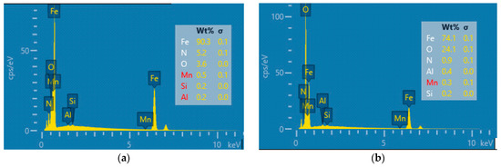
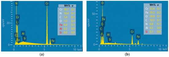
The Cr/CrN PVD coating is characterized by a higher hardness and better corrosion resistance in a 3.5% NaCl environment. The above-mentioned properties of the coating determine the course of elementary wear mechanisms in the tribocorrosion process. At the lowest tested load value, the PVD coating (Figure 10a) has a milder abrasive wear (shallow grooves) compared to the gas nitrided one. In the case of an average tested load value (13 N), the grooves appear less frequently, and the wear is of a milder form (Figure 10b). Figure 12 compares the chemical composition of the sample inside the local cavity (Figure 10b—area 2) and within its vicinity in the area of a uniform material defect (Figure 10b—area 1). The significantly lower content of chromium and nitrogen may indicate a large pit depth. The higher hardness of the Cr/CrN PVD coating ensures greater resistance to plastic deformation and adhesion. Therefore, the detachment of larger fragments of the material occurs only locally at the highest loads (Figure 10c). Similar tribocorrosion mechanisms were observed in other studies [17,35,36,37].
Local cavities in the wear trace, which are important for the formation of the synergy of friction and corrosion, are the result of local corrosion processes. It may be proved by the fact that such forms of damage do not occur under conditions of cathodic polarization. The surface of the wear trace following the tribocorrosion tests under cathodic polarization is shown in Figure 13. In comparison with the traces obtained at the OCP potential, there are no visible local pits (for both materials). Such pits do not form under cathodic polarization conditions. Generally, material loss occurs as a result of abrasive wear.
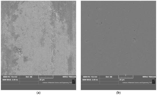
Figure 13.
Pictures of the wear trace surface at an open circuit potential, EOCP, under the load of 13 N: (a) gas nitrided with subsequent oxidation and impregnation, (b) Cr/CrN PVD.
In the case of both tested material solutions (despite the significant difference in hardness and resistance to tribocorrosion), it was found that a common mechanism for generating the synergy of friction and corrosion is likely. This mechanism is related to the formation of local cavities along the friction path. The formation of local cavities (pits) is favored by corrosive interactions in the frictional matching and susceptibility to cracking of the hard surface layer. No pitting was observed under cathodic polarization conditions. The concentration of stress around a local cavity promotes plastic deformation of the surface layer. The cyclical nature of these interactions related to the displacement of the contact zone in the tested sliding node may lead to fatigue cracking of the deformed layer—tearing off larger pieces of material. Such forms of wear were observed at the highest pressures in the contact zone. Under the analyzed conditions (the test conditions), the described tribocorrosion mechanism seems to be common for materials of high hardness. It needs to be noted, however, that the above conclusion is based on a comparative analysis that included only two material solutions.
5. Conclusions
Attempts were made in the article to find possible mechanisms of tribocorrosion that would be common to materials of high hardness. It was found that synergy of friction and corrosion can be generated by the same mechanisms associated with the formation of local cavities (pits) on the hard surface layer for both materials. It was also observed that the intensity of these mechanisms is determined by material hardness. A comparative analysis of tribocorrosion process was carried out only for two material solutions of high and different hardness. Under the analyzed conditions (the test conditions), the described tribocorrosion mechanism can be considered as characteristic of high hardness materials.
- The Cr/CrN PVD coating produced on AISI 1045 medium carbon steel provides better tribocorrosion resistance than the gas nitrided with subsequent oxidation and impregnation coating in a 3.5% NaCl environment. This relation applies to the entire range of loads in the contact zone which were applied during the tribocorrosion tests.
- In tribocorrosion tests, a clear synergy effect of friction and corrosion was identified for both tested material solutions. It was over 30% in both cases. A similar percentage of the synergy effect, despite the clear difference in the total tribocorrosive loss, may indicate that similar elementary destruction mechanisms occur in the case of both analyzed material solutions.
- According to the diagnosed fundamental tribocorrosion mechanisms, the synergy effect is caused by the fact that corrosion processes create local cavities which at successive time intervals are most likely to intensify mechanical wear. The area around the cavities facilitates plastic deformation, the initiation of cracking of cyclically deformed layers and the tearing off larger fragments of material (especially at higher unit pressures in the frictional contact zones).
Author Contributions
Conceptualization, A.S. and M.K.; methodology, A.S. and M.K.; investigation, A.S. and M.K.; writing—original draft preparation A.S. and M.K.; writing—review and editing, M.K.; supervision, A.S. All authors have read and agreed to the published version of the manuscript.
Funding
This research received no external funding.
Institutional Review Board Statement
Not applicable.
Informed Consent Statement
Not applicable.
Data Availability Statement
Data is contained within the article.
Conflicts of Interest
The authors declare no conflict of interest.
References
- Cao, S.; Mischler, S. Modeling tribocorrosion of passive metals—A review. Curr. Opin. Solid State Mater. Sci. 2018, 22, 127–141. [Google Scholar] [CrossRef]
- Ghanbarzadeh, A.; Salehi, F.M.; Bryant, M.; Neville, A. A new asperity-scale mechanistic model of tribocorossive wear: Synergistic effect pf mechanical wear and corrosion. J. Tribol. 2019, 141, 1–12. [Google Scholar] [CrossRef]
- Jemmely, P.; Mischler, S.; Landolt, D. Electrochemical modeling of passivation phenomena in tribocorrosion. Wear 2000, 237, 63–76. [Google Scholar] [CrossRef]
- Ghanbarzadeh, A.; Salehi, F.M.; Bryant, M.; Neville, A. Modelling the evolution of electrochemical current in potentiostatic condition using and asperity-scale model of tribocorrosion. Biotribology 2019, 17, 19–29. [Google Scholar] [CrossRef]
- Landolt, D.; Mischler, S.; Stemp, M. Electrochemical methods in tribocorrosion: A critical appraisal. Electrochim. Acta 2001, 46, 3913–3929. [Google Scholar] [CrossRef]
- Bayon, R.; Igartua, A.; Fernandez, X.; Martinez, R.; Rodriguez, R.J.; Garcia, J.A.; de Frutos, A.; Arenas, M.A.; de Damborenea, J. Corrosion-wear behaviour of PVD Cr/CrN multilayer coatings for gear applications. Tribol. Int. 2009, 42, 591–599. [Google Scholar] [CrossRef]
- Ould, C.; Badiche, X.; Montmitonnet, P.; Gacho, Y. PVD coated mill rolls for cold rolling of stainless-steel strips—Tribological and mechanical laboratory tests. J. Manuf. Process. 2013, 15, 77–86. [Google Scholar] [CrossRef]
- Ginting, A.; Skein, R.; Cuaca, D.; Herdianto; Pieter, Z.; Masyithah, Z. The characteristics of CVD- and PVD-coated carbide tools in hard turning of AISI 4340. Measurement 2018, 129, 548–557. [Google Scholar] [CrossRef]
- Malvajerdi, S.S.; Malvajerdi, A.S.; Ghanaatshoar, M. Protection of CK45 carbon steel tillage tools using TiN coating deposited by an arc-PVD method. Ceram. Int. 2019, 45, 3816–3822. [Google Scholar] [CrossRef]
- Gupta, K.M.; Ramdev, K.; Dharmateja, S.; Sivarajan, S. Cutting characteristics of PVD coated cutting tools. Mater. Today Proc. 2018, 5, 11260–11267. [Google Scholar] [CrossRef]
- Baptista, A.; Silva, F.; Porteiro, J.; Miguez, J.; Pinto, G. Sputtering physical vapour deposition (PVD) coatings: A critical review on process improvement and market trend demands. Coatings 2018, 8, 402. [Google Scholar] [CrossRef]
- Sousa, V.F.C.; Silva, F.J.G. Recent advances on coated milling tool technology—A comprehensive review. Coatings 2020, 10, 235. [Google Scholar] [CrossRef]
- Liu, C.; Leyland, A.; Bi, Q.; Matthews, A. Corrosion resistance of multi-layered plasma-assisted physical vapor deposition TiN and CrN coatings. Surf. Coat. Technol. 2001, 141, 164–173. [Google Scholar] [CrossRef]
- Ibrahim, M.A.M.; Korablov, S.F.; Yoshimura, M. Corrosion of stainless steel coated with TiN, (TiAl)N and CrN in aqueous environments. Corros. Sci. 2002, 44, 815–828. [Google Scholar] [CrossRef]
- Su, Y.L.; Yao, S.H.; Wu, C.T. Comparison of characterizations and tribological performance of TiN and CrN deposited by cathodic arc plasma deposition process. Wear 1996, 199, 132–141. [Google Scholar] [CrossRef]
- Chen, Q.; Cao, Y.; Xie, Z.; Chen, T.; Wan, Y.; Wang, H.; Gao, X.; Chen, Y.; Zhou, Y.; Guo, Y. Tribocorrosion behaviors of CrN coating in 3,5 wt% NaCl solution. Thin Solid Films 2017, 622, 41–47. [Google Scholar] [CrossRef]
- Shan, L.; Wang, Y.; Zhang, Y.; Zhang, Q.; Xue, Q. Tribocorrosion behaviors of PVD CrN coated stainless steel in seawater. Wear 2016, 362–363, 97–104. [Google Scholar] [CrossRef]
- Shan, L.; Zhang, Y.-R.; Wang, Y.-X.; Li, J.-L.; Jiang, X.; Chen, J.-M. Corrosion and wear behaviors of PVD CrN and CrSiN coatings in seawater. Trans. Nonferr. Met. Soc. China 2016, 26, 175–184. [Google Scholar] [CrossRef]
- Shan, L.; Wang, Y.; Li, J.; Jiang, X.; Chen, J. Improving tribological performance of CrN coatings in seawater by structure design. Tribol. Int. 2015, 82, 78–88. [Google Scholar] [CrossRef]
- Marin, E.; Offoiach, R.; Regis, M.; Fusi, S.; Lanzutti, A.; Fedrizzi, L. Diffusive thermal treatments combined with PVD coatings for tribological protection of titanium alloys. Mater. Des. 2016, 89, 314–322. [Google Scholar] [CrossRef]
- Bayon, R.; Nevshupa, R.; Zubizarreta, C.; Ruiz de Gopegui, U.; Barriga, J.; Igartua, A. Characterisation of tribocorrosion behaviour of multilayer PVD coatings. Anal. Bioanal. Chem. 2010, 396, 2855–2862. [Google Scholar] [CrossRef]
- Ye, Y.; Wang, Y.; Chen, H.; Li, J.; Yao, Y.; Wang, C. Doping carbon to improve the tribological performance of CrN coatings in seawater. Tribol. Int. 2015, 90, 362–371. [Google Scholar] [CrossRef]
- Song, G.-H.; Yang, X.-P.; Xiong, G.-L.; Lou, Z.; Chen, L.-J. The corrosive behawior of Cr/CrN multilayer coatings with different modulation periods. Vacuum 2013, 89, 136–141. [Google Scholar] [CrossRef]
- Kowalski, M. The Improvement of Tribocorrosion Performance of Structural Steel Components in Marine Environment. Ph.D. Thesis, Warsaw University of Technology, Warsaw, Poland, 2018. [Google Scholar]
- Michalski, J.; Iwanow, J.; Tacikowski, J.; Tarfa, T.N.; Tymowski, J.; Sułkowski, I.; Wach, P. Anticorrosion nitriding with post-oxidation and inhibitor impregnation, and its industrial applications. Heat Treat. Met. 2004, 2, 31–35. [Google Scholar]
- EN ISO 6507-1 Metallic Materials—Vickers Hardness Test—Part 1: Test Method; European Committee for Standarization: Brussels, Belgium, 2005.
- Vidakis, N.; Antoniadis, A.; Bilalis, N. The VDI 3198 indentation test evaluation of a reliable qualitative control for layered compounds. J. Mater. Process. Technol. 2003, 143–144, 481–485. [Google Scholar] [CrossRef]
- Stachowiak, A.; Zwierzycki, W. Tribocorrosion modeling of stainless steel in a sliding pair of pin-on-plate type. Tribol. Int. 2011, 44, 1216–1224. [Google Scholar] [CrossRef]
- Kowalski, M.; Stachowiak, A. Tribocorrosion performance of Zn, Zn–Ni with magnesium electrodeposited on medium carbon steel in a chloride environment. Surf. Coat. Technol. 2019, 366, 75–85. [Google Scholar] [CrossRef]
- Mischler, S.; Debaud, S.; Landolt, D. Wear accelerated corrosion of passive metal in tribocorrosion systems. J. Electrochem. Soc. 1998, 145, 750–758. [Google Scholar] [CrossRef]
- Jemmely, P.; Mischler, S.; Landolt, D. Tribocorrosion behavior of Fe-17Cr stainless steel in acid and alkaline solutions. Tribol. Int. 1999, 32, 295–303. [Google Scholar] [CrossRef]
- ASTM G119-09. Standard Guide for Determining Synergism between Wear and Corrosion; ASTM International: West Conshohocken, PA, USA, 2016. [Google Scholar]
- Sun, Y. Tribocorrosive behavior of low temperature plasma-nitrided PH stainless steel sliding against under linear reciprocation with and without trensvere oscillations. Wear 2016, 362–363, 105–113. [Google Scholar] [CrossRef]
- Baranowska, J.; Franklin, S.E.; Kochmanska, A. Wear behaviour of low-temperature gas nitrided austenitic stainless steel in a corrosive liquid environment. Wear 2007, 263, 669–673. [Google Scholar] [CrossRef]
- Hacisalihogu, I.; Yildiz, F.; Celik, A. Tribocorrosion behavior of plasma nitrided Hardox steels in NaCl solution. Tribol. Int. 2018, 120, 434–445. [Google Scholar] [CrossRef]
- Naghibi, S.A.; Ksolution, R.; Fathi, M.H. Corrosion and tribocorrosion behawior of T/TiN PVD coating on 316L stainless steel substrate in Ringer’s. Mater. Chem. Phys. 2014, 148, 614–623. [Google Scholar] [CrossRef]
- Kok, Y.N.; Akid, R.; Hovsepian, P.E. Tribocorrosion testing of stainless steel (SS) and PVD coated SS using a modified scanning reference electrode technique. Wear 2005, 295, 1472–1481. [Google Scholar] [CrossRef]


Publisher’s Note: MDPI stays neutral with regard to jurisdictional claims in published maps and institutional affiliations. |
© 2021 by the authors. Licensee MDPI, Basel, Switzerland. This article is an open access article distributed under the terms and conditions of the Creative Commons Attribution (CC BY) license (http://creativecommons.org/licenses/by/4.0/).