Article

Interface Characteristics and Anticorrosion Performances of Cold Galvanizing Coatings Incorporated with γ-chloropropyl Triethoxysilane on Hot-Dip Galvanized Steel

1
Key Laboratory of Nuclear Materials and Safety Assessment, Institute of Metal Research, Chinese Academy of Sciences, Shenyang 110016, China
2
School of Materials Science and Engineering, University of Science and Technology of China, Hefei 230026, China
3
Institute of Corrosion Science and Technology, Guangzhou 510530, China
*
Author to whom correspondence should be addressed.
Coatings 2021, 11(4), 402; https://doi.org/10.3390/coatings11040402
Submission received: 15 February 2021 / Revised: 11 March 2021 / Accepted: 12 March 2021 / Published: 31 March 2021
(This article belongs to the Section Corrosion, Wear and Erosion)

Abstract

:
The cold galvanizing coatings (CGCs) are used to repair old hot-dip galvanized steel (HDG) in numerous anticorrosion engineering, but poor adhesion of the CGC restricts its large-scale applications in the industries. For the purpose of overcoming the weak adhesion problems of the CGC on HDG, γ-chloropropyl triethoxysilane (CPTES) was added directly into cold galvanizing coatings (CPTES/CGC). Interface characteristics and related corrosion protection behaviors were investigated by the pull-off adhesion test, water contact angle measurements, Fourier transform infrared spectroscopy (FTIR), X-ray photoelectron spectroscopy (XPS), scanning electron microscope (SEM), and electrochemical tests. The experimental results revealed that, there is an increase by 19.1% of the CPTES/CGC surface free energy when compared with that of CGC. In addition, Si–O–Si and Si–O–Zn bonds were found in the CPTES/CGC, which indicate new network structures formed inside the CPTES/CGC, between the interface of the CPTES/CGC and HDG substrate, resulting in dry adhesion, wet adhesion, and the cathodic protection time of CPTES/CGC increased by 50% and 200% and 300% respectively compared with the CGC.

1. Introduction

Hot-dip galvanization (HDG) has been widely applied to the steel structure from corrosion for decades because of their good galvanic protection and barrier protection [1]. The galvanized layer can provide corrosion resistance for the steel substrate for a period of time when exposed in the general atmospheric environment. However, the time of protective effect will be greatly shortened in moist and aggressive environments [2,3]. Pretreatment and coating protection were effective ways to prolong the lifetime of the HDG constructions [4,5,6,7,8].
Zinc-rich coatings is that in which the ratio of the pigment volume concentration is greater than the critical pigment volume concentration, which enables an aqueous electrolyte to penetrate and allow the sacrificial action of zinc particles, containing 92% (w/w) zinc particles, the volume fraction of zinc particles was only 52% and 19.4% was occupied by air [9,10]. Cold galvanizing coatings (CGCs) serve as a new-type of one-component zinc-rich organic coating that boasts of low-cost, easy construction, and good anticorrosion properties has been regarded as suitable for the coating protection of HDG [11]. In a bid to improve the corrosion resistance of zinc-rich coatings, researchers have developed various ways to prolong the lifetime of zinc-rich coatings. Such as modification of the zinc particles [12,13,14], fabrication of repairable superhydrophobic surfaces [15], change of shape and size of zinc particles [16,17], changes in the pigment/binder ratio [18,19], and incorporation of metal or nonmetal pigments [20,21,22,23]. Almost all the above studies have been focused on improving the corrosion protection efficiency and barrier properties of zinc-rich coatings, which include extending the diffusion path of corrosive solution, decreasing coating porosity, strengthening the electroconnection of the pigments, and reducing electrochemical activities of zinc particles. However, the weak adhesion between the cold galvanizing coating and HDG substrate greatly reduced the lifetime of the coating. Therefore, the cold galvanizing coatings confront a big challenge of durability.
Silane coupling agents have a generic chemical structure: ( XO ) 3 Si ( CH 2 ) n Y , where XO is a hydrolyzable alkoxy group, which can be methoxy (OCH3), ethoxy (OC2H5), or acetoxy (OCOCH3). Y is an organofunctional group such as vinyl (C=C) or amino (NH2), which is responsible for good paint adhesion of a silane-treated metal surface. Consequently, it has recently received greater attention due to its excellent properties such as an adhesion promotion [24,25], mechanism strength improvement [26,27], cross-linking reinforcement [28,29,30], and coating anticorrosion improvement [31,32,33]. A lot of efforts have been made to apply these materials as adhesion promoters between metallic substrates and organic coatings for protection against a corrosion phenomenon. The effect of silane functionalized graphene oxide on corrosion protection performance of coatings has been evaluated by Sepideh Pourhashem [25], which showed that the coating adhesion to the metallic substrate and the water contact angle of the coating have increased. Ji, W.G. et al. [31] added 3-glycidoxypropyltrimethoxy silane directly to the coating system, and the results showed that water uptake of epoxy coating decreases remarkably. M. F. Montemor et al. [34] used bis-silane films modified with particles of SiO2 pretreated galvanized steel substrates, and found out that the addition of silica particles improves corrosion protection due to the formation of a thicker silane film and/or enhanced barrier properties provided by the inner layers of the silane film. However, few literatures reported the improvement of interface properties between zinc-rich coatings and HDG substrates.
In this work, cold galvanizing coating (CGC) was modified by γ-chloropropyl triethoxysilane (CPTES). The physicochemical properties of the modified coating (CPTES/CGC) were analyzed using various surface characterization techniques, while the adhesion strength of coating with immersion time was tested, and the anticorrosion protection properties were investigated by the electrochemical technique.

2. Experimental

2.1. Materials and Chemicals

The hot-dip galvanized steel and zinc particles (chemical composition: Fe: 0.002%, Cd: 0.002%, Pb: 0.005%, and Zn: 99.99%) were obtained from Hunan Fuhong Zinc Chemicals Co., Ltd., Changsha, China, which were spherical in shape and average particle size range of 3– 5   μ m . SE200 resin was supplied by Shenyang Zhongke Engineering Technology Center for Corrosion Control, Shenzhen, China. CPTES were procured from Shanghai Macklin Biochemical Co., Ltd., Shanghai, China. The CPTES is known to contain chloropropyl and the alkoxy hydrolysable substituents and the chemical structure is ClCH 2 CH 2 CH 2 Si ( OC 2 H 5 ) 3 . Xylene serves as the solvent, which was purchased at Sinopharm Chemical Reagent Co., Ltd., Shenyang, China.

2.2. Preparation of Coated Steel Panels

Zinc powder, resin, and silane were dispersed according to the formulation listed in Table 1. All ingredients were dispersed at 2000 rpm with high-speed disperser for 30 min, hot-dip galvanized steel sheets were ultrasonically treated with acetone in order to remove grease on the surface. The coatings were sprayed on the steel sheets by air-spraying; air pressure range of 0.6–0.8 MPa, and then cured at room temperature for 7 days. The thickness of coatings was 80   ±   10   μ m , which were measured by a portable thickness measurement system (Positector 6000, Ogdensburg, NY, USA).

2.3. Pull-Off Adhesion Measurements

The adhesion of the coatings at different immersion time in 3.5 wt % NaCl solution were tested by the PosiTest adhesion tester (AT-M, ELECTROMATIC Equipment Co., Inc. Cedarhurst, NY, USA) according to ISO 4624: 2016 [35]. Dollies of the 20 mm diameter were glued to the surface of coatings by using a double-component epoxy adhesive. Then, a slot was made around dollies, which were pulled at a speed of 0.5 MPa/s relative to the coating surface until the dollies were detached from the coated substrate. The measurements were done on the samples before (dry adhesion) and after (wet adhesion) 20 days immersion in 3.5 wt % NaCl solution. For each coating system, 10 determinations were carried out for all samples and the average value was taken. All the samples were kept in a temperate and humid chamber at 25 ± 2 °C, 50% ± 5% humidity for at least 16 h before the pull-off test.

2.4. Water Contact Angle

Water contact angle (CA) was tested by the water contact measuring device (POWEREACH JC2000D1, Shanghai zhongchen Digital Technology Apparatus Co., Ltd., Shanghai, China). Consider the wetting process between water/coating interfaces, 3 μL of a distilled water droplet were dropped on the coating surfaces at ambient temperature and images were collected after 10 s. By measuring five different spots on a sample and then obtain the value of CA by goniometry.

2.5. Characterization

The microstructures of the surface and cross-sectional microscopic views of the coated sample after experiments were observed via scanning electron microscope (Philips XL 30 type Field Emission ESEM, FEI, Hillsboro, OR, USA). The chemical bonding information was determined by X-ray photoelectron spectroscopy (Escalab 250, Thermo, Waltham, MA, USA) with 150-W Al Ka radiation at 1486.6 eV and the results were fitted and optimized by XPSPEAK4.1 software. The chemical grafting and functional groups from the coated panels were determined by Fourier transform infrared spectroscopy within the wavelength range of 400–4000 cm−1 (IS50 FT-IR, Thermo scientific, Waltham, MA, USA).

2.6. Electrochemical Corrosion Tests

Potentiodynamic polarization curves and electrochemical impedance spectroscopy (EIS) testing of the prepared coated panels was evaluated by PARSTAT 4000 (Princeton, NJ, USA) electrochemical workstation, using 3.5 wt % NaCl solution as an electrolyte. A three-electrode arrangement was used with a platinum counter electrode, a saturated calomel reference electrode and the coated panel as a working electrode with a testing area of about 1 cm2 and 12.56 cm2, respectively. Before EIS measurements, the samples were put into the electrolyte solution for 30 min to obtain a stable open circuit potential (OCP). The potentiodynamic polarization curves were measured at a scan rate of 0.167 mV/s and range of ± 0.25   V vs. OCP. A frequency range of 10−2–105 Hz were used for the EIS measurements with a total of 50 points distributed logarithmically, and the sinusoidal perturbation was 20 mV at an open circuit potential. At least three samples were tested to confirm the repeatability of the results.

3. Results and Discussion

3.1. Wettability

Figure 1 exhibits the surface morphologies and the corresponding optical photographs for different coatings. As for blank CGC, there were few small bulges and pits were exhibited and the wettability result for the coating gave the water contact angles as 98.5 ° . Fewer pits and no obvious bulges appeared on CPTES/CGC, which gave the contact angle as 91°. According to Zhang, D., et al. [36,37], increasing the surface hydrophobicity reduces water wetting on coatings and thus, their interaction with water, thereby prolonging their barrier effects and service lives. Decreased hydrophobicity implies greater wettability and stronger adhesion strength to HDG substrates. Correspondingly, corrosive electrolyte solution will be penetrated more susceptibly through pores or defects when the CPTES/CGC was exposed to the electrolyte solution in the early stage because of decreased hydrophobicity. The effect with corrosion behavior and electrochemical properties of increased wettability of coating surface coating will be discussed in Section 3.4.
Besides that, work of adhesion (W) and surface free energy ( γ sv ) were calculated by Young’s Equation (1) and Neumann’s Equation (2).
W a   =   γ lv ( 1   +   cos θ )
W a   = 2 ( γ lv γ sv ) 0.5 exp [ β ( γ lv γ sv ) 2 ]
where γ lv is the surface tension of water (7.28 μ J / cm 2), γ sv is the surface free energy of the coating, θ is the CA of water and β is a single parameter 0.01247 (μJ/cm2)−2 that will not change from system to system [38,39]. The two equations can be solved numerically and the results presented in Table 2. It is clearly seen that CPTES/CGC decreased the CA by about 7.6% compared to the CGC. The surface free energy and work of adhesion were also decreased. These results indicated that the incorporation of silane caused the increased hydrophilicity and wettability of the coating surface. According to H. Vakili et al. [40], chemistry of the coating sample is an influential parameter affecting the surface free energy except morphology. Therefore, it can be understood that there are more hydroxyl groups after the silane hydrolysis reaction in the coating, which show a high tendency to make hydrogen bonds with water molecules.

3.2. FT-IR and XPS Analysis

FTIR is a sensitive technique for surface functional group analysis of material surfaces [41]. Figure 2 shows the FTIR spectrum of CGC, CPTES/CGC, and CPTES. For CGC and CPTES/CGC, the peak at 2962, 2874, and 1602 cm−1 can be attributed to –CH3, –CH2, and benzene ring stretching vibration, respectively [42,43]. Additionally, the absorption peaks at 1163, 1453, and 1743 cm−1 belong to the C–O–C, CH=CH, and the C=O vibration of the ester carbonyl of resin main chain, respectively [43]. For CPTES, the absorption peaks at 1100, 1075, and 952 cm−1 are related to the Si–O band, and the peaks at 1169, 860, and 785 cm−1 arose from O–C, C–Si, and C-H bands, respectively [42]. After addition of CPTES to the resin, the existence of residual Si–OH (at 960 cm−1) and of characteristic bands of the ethanol (at 880 cm−1) group indicates that the hydrolysis/condensation reactions are a slow process. Combined with the presence with Si–OH and characteristic bands of ethanol, the bands appear at 1104, 1079, and 476 cm−1, which are assigned to the Si–O–Si bands between resin and the silane agent or residual of siloxane [25,42]. Meanwhile, the peak at 1031 cm−1 is a characteristic of Si–O–C bands. These results confirmed that silane molecules were successfully grafted onto the resin main chain.
Besides that, by peeling the coating from the HDG substrates, the interface chemical composition between the coating and HDG substrates were also determined by XPS. Figure 3 shows the XPS curves fit spectra of CGC and CPTES/CGC. The C 1s peaks of CGC and CPTES/CGC (Figure 3a,c) can be deconvoluted into four components: C = C , C–C, C–O, and COOH, and the bonding energies are centered at about 284.2, 284.8, 286.5, and 288.5 eV, respectively [44]. However, obvious distinctions in the category of surface functional groups can be observed in C 1s peaks of CPTES/CGC, the peaks at 283.2 and 286.7 eV were assigned to the C–Si and C–O–Si bond. The presence of the C–O–Si bond suggests that CPTES was strongly bonded to the resin. As shown in Figure 3b,d, two peaks of O 1s at 531.9 and 533.0 eV are attributed to C=O and C–O, the appearance of two new peaks corresponding to Si–O–Si at 531.7 eV and O–Zn at 533.7 eV, suggest that the Si–O–Si crosslinking network was formed and chemically bonded to the substrate. The main peaks of Si–O–C at 101.3 eV, Si–O–Zn at 102.1 eV, Si–C at 102.6 eV, and Si–O–Si at 103.8 eV of Si 2p reinforced this point further [45,46]. Meanwhile, the peak at around 199.9 eV is ascribed to the C–Cl bond of CPTES, which indicates the stability of Cl at the tertiary carbon atom. The XPS results indicated that CPTES reacted with the carboxyl and hydroxyl groups of the resin, the dehydration condensation reaction occurred between the silane molecules, and between silane and the substrate simultaneously.

3.3. Pull-off Adhesion Measurements

The value of adhesion strength was measured and the results are presented in Table 3. Additionally, A is a cohesive failure of the substrate; B is a cohesive failure of the first coating (in our samples, the first coating is the cold galvanizing coating). The 50% A/B represents the paint system breaks at an area on each side of the site of separation, revealing a mean of approximately 50% of the dolly area associated with cohesive failure between the substrate and coating, and the 50% B represents the dolly area associated with a cohesive failure of the coating. It was observed that the CPTES/CGC was better than CGC and the CPTES/CGC showed greater adhesion strength than CGC before and after the immersion test. The digital photo of the coating failure after pull-off was also shown in Figure 4. It can be seen that approximately 50% cohesive failure of the CGC was between the coating and the substrate, while the CGC broke within the coating. According to the previous study [33], it can be understood that the excellent adhesion between CPTES/CGC and HDG substrate was caused by the enrichment of silane and Si–O–Me was formed at the substrate. The wet adhesion properties of the coatings after 20 days immersion in 3.5 wt % of NaCl solution were also studied. The adhesion loss was then calculated according to the equation:
Adhesion   loss   = Dry   adhesion   strength Wet   adhesion   strength Dry   adhesion   strength   ×   100 %
The results from Table 3 revealed that the adhesion loss value of CPTES/CGC were much lower than the CGC. It is well known that electrolyte diffusion into the coating/substrate interface is responsible for the coating adhesion loss. The hydroxyl ion ( OH ) created at the coating/substrate interface as a result of cathodic reaction ( 2 H 2 O   +   O 2   +   4 e     4 OH ) can result in the increase of pH beneath the coating, causing the adhesion bonds to break down [40]. The results of adhesion loss can be understood by the following reasons: (1) there are more adhesive bonds in CPTES/CGC than CGC. (2) CPTES/CGC has less pores and channels because of a crosslinking network, which prevents the permeation of electrolyte to the interface of the coating/substrate. Therefore, the CPTES/CGC has a better ability to resist the cathodic alkalization than CGC.
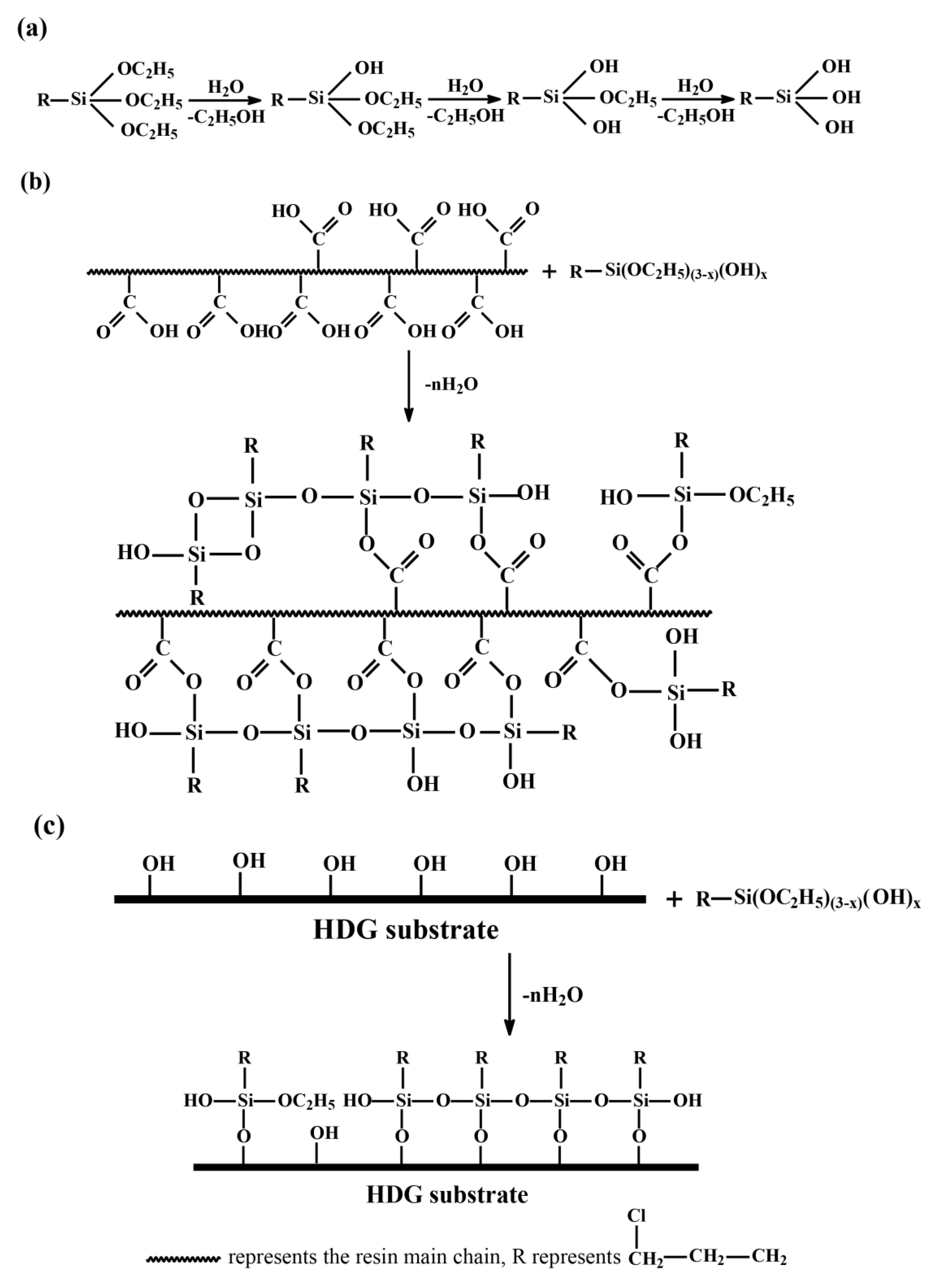
The reaction mechanism of CPTES in the coating is shown in Figure 5. The formation of the crosslinking network and siloxane network involves two reaction stages. The first hydrolysis reactions are a stepwise hydrolysis process and shown in Figure 5a, where R represents the γ-chloropropyl group and x is an integer that ranges between 1 and 3. All three hydrolysis products are present in the reaction system and participate in the second step that is the condensation to oligomers and the formation of hydrogen bonds with the resin (Figure 5b) and HDG substrates (Figure 5c). There is usually one bond from each silicon at the interface between the coating and HDG substrate, the remaining two bonds are present either in the free or condensed form. Additionally, the covalent bonds formation is known to occur with some level of reversibility; bonds formation, breaking, and reformation in order to relieve internal stress during the formation process of the siloxane network and crosslinking network. After the hydrolysis reaction, the other reactions are known to occur concurrently [47].

3.4. Electrochemical Measurements

3.4.1. OCP and Potentiodynamic Polarization

It is commonly believed that the galvanic effect comes from zinc particles that are electrically connected to the steel substrate and electrochemical processes proceeding in such systems are the oxidation of zinc particles (Equation (4)) and the reduction of the dissolved oxygen (Equation (5)) [48].
Zn     Zn 2 +   +   2 e
O 2   +   2 H 2 O   +   4 e     4 OH
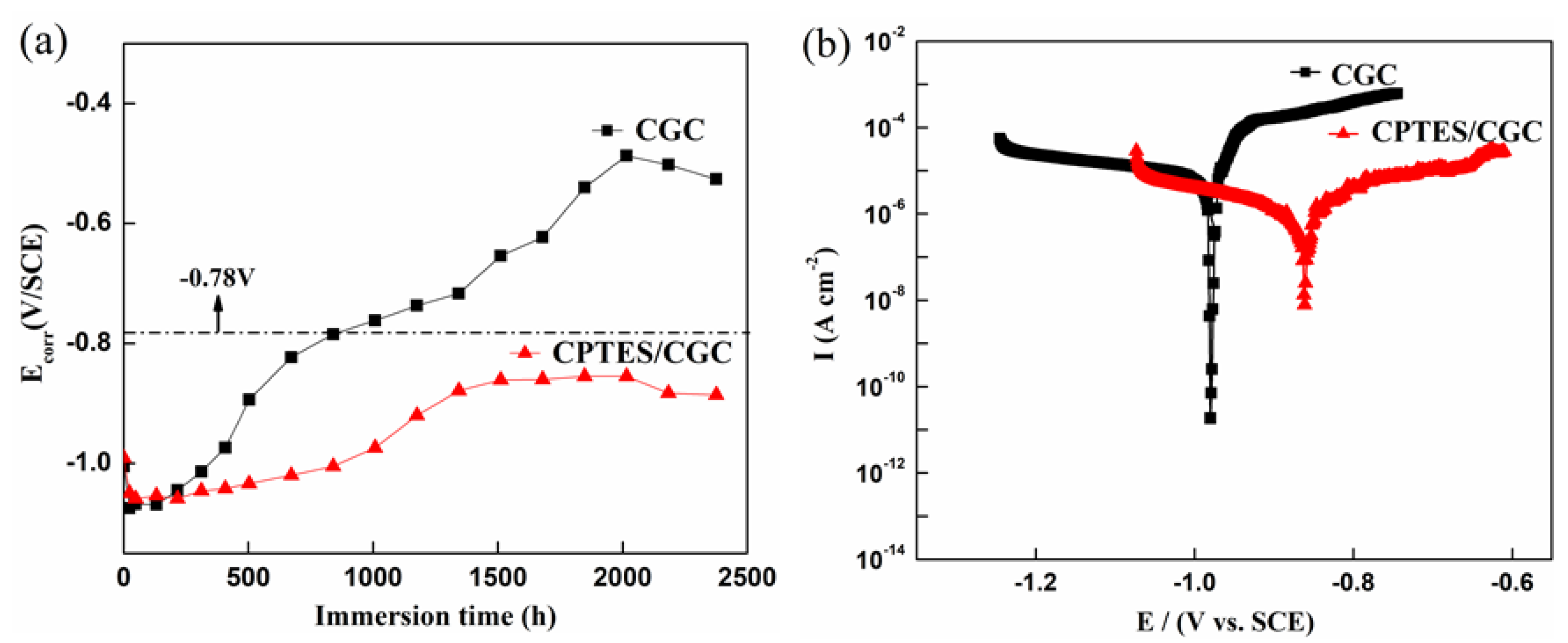
The evolution of the free corrosion potential of CGC and CPTES/CGC were measured and presented in Figure 6a. All of the potential evolutions of the coatings show a period of decrease for a few hours and reached the lowest point of −1.08 V/SCE. According to Aberu et al. [49], the potential decrease process corresponds to the active progress of the zinc particles, which implies an increase in cathodic protection intensity. This result demonstrates that the addition of silane would not influence the permeation of Cl and other aggressive ions during the beginning stage of immersion process. By prolonging the immersion time, the zinc particles were consumed and an increase of EOCP was observed for both coatings during the immersion. This is because, the active area of the particles was reduced, caused by the corrosion products around the zinc particles and the electrical connection between the particles and the steel substrate was also weakened by the corrosion products. However, the EOCP of CGC rose rapidly to −0.78 V/SCE in the following hundred hours, while the EOCP of CPTES/CGC rose slower than that of CGC in which the time for corrosion protection is twice more than the time for CGC. Particularly for CPTES/CGC, the time for corrosion protection is over three times more than that of CGC and reached more than 2500 h, hence the coating still provides sacrificial anode protection for the steel substrate.
Corrosion behavior was also evaluated by the potentiodynamic polarization technique. Before potentiodynamic polarization measurements, the samples were put into the 3.5 wt % NaCl solution for 0.5 h to obtain a stable open circuit potential. Figure 6b depicts the potentiodynamic polarization curves of non-silane and silane incorporated coatings, which was measured under the same conditions. Corrosion potentials (Ecorr), corrosion current densities (Icorr) and Tafel constants (Ba and Bc) obtained by Tafel fit in the vicinity of the strong polarization zone are listed in Table 4. It can be seen from Table 4 that all CPTES/CGC showed more positive Ecorr and more negative Icorr than CGC. Meanwhile, the Ecorr value of CPTES/CGC was −0.85 V/SCE while that of CGC was −0.98 V/SCE and the Icorr of CPTES/CGC (1.55 × 10⁻⁶ A/cm2) was more than one order of magnitude lower than that of CGC (8.59 × 10⁻⁵ A/cm2). Additionally, the value of polarization resistance (Rp) was used to determine the protective ability of coatings, which was directly related to the corrosion rate and can be calculated from Equation.
R p = B a B c 2.303 I corr ( B a + B c )
Additionally, correspond to the Icorr values, RP reached 4.74 × 10⁵ Ω · cm2. Thus, CPTES/CGC showed better corrosion resistance than other coatings. However, the corrosion resistance capability of the coating for HDG substrate still needs to be confirmed with the following measurements.

3.4.2. Electrochemical Impedance Spectroscopy Test

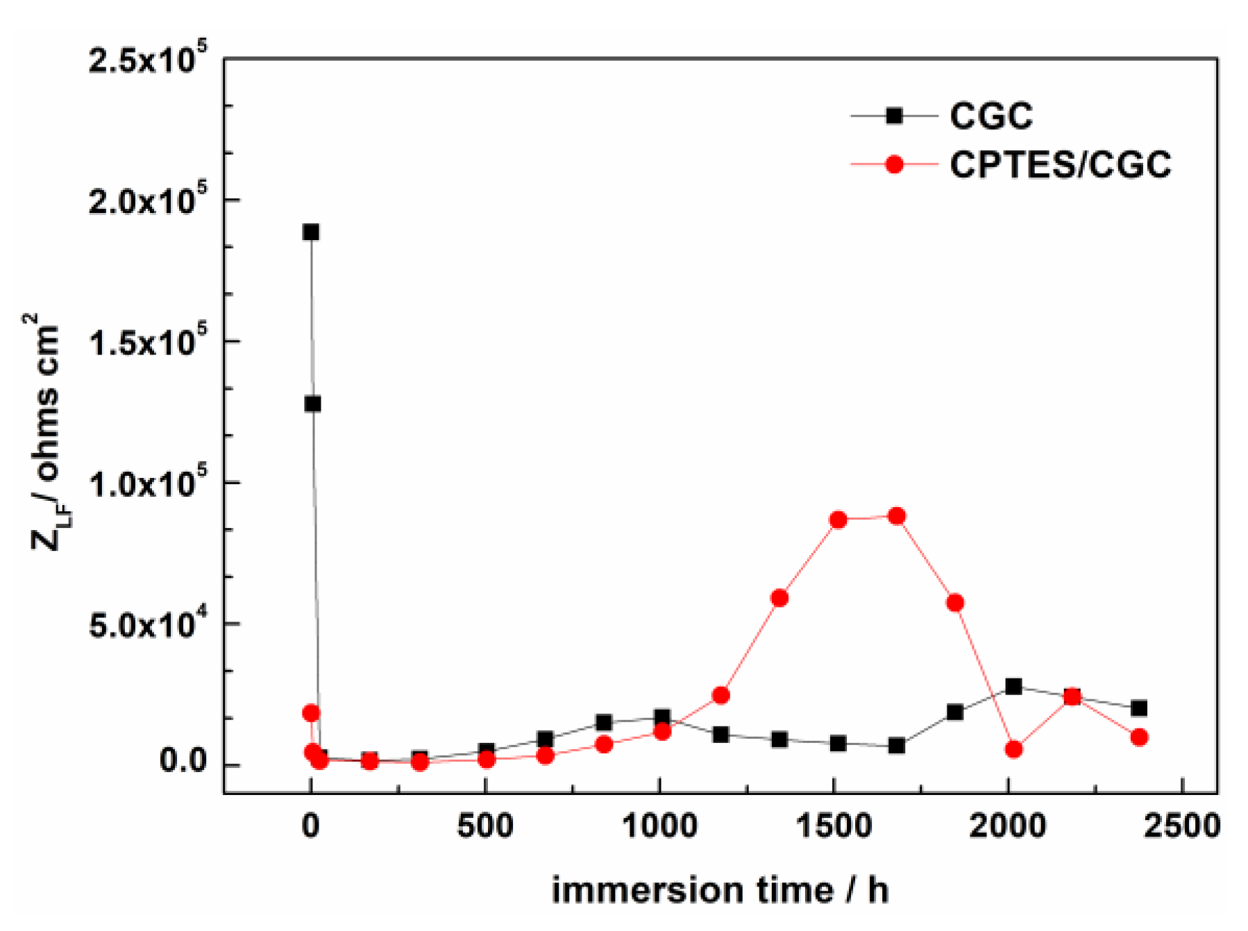
In order to investigate the influence of the CPTES on the electrochemical properties of the coatings, the coating samples with and without silane were immersed in 3.5% NaCl solution and EIS was used to evaluate their anti-corrosion performance. The evolution of low frequency (LF) modulus ZLF ( | Z = 0.01   Hz | ) with immersion time was shown in Figure 7. The values of ZLF, which are related to the diffusion of the electrolyte in the pores of the coatings, are commonly used to evaluate the corrosion resistance of the coatings. At higher ZLF, the diffusion of the electrolyte in the pores of the coatings will be blocked more tempestuously, suggesting lower porosity of the coatings or longer distance for electrolyte diffusion to the zinc surface [7,50]. From Figure 6 it can be seen that the ZLF of CGC reached a high at about 1.89 × 10⁵ Ω · cm2, while CPTES/CGC showed a low and was 1.85 × 10⁴ Ω · cm2. By prolonging the beginning immersion time, the ZLF of CPTES/CGC at 5 h decreased gradually to 1500   Ω · cm 2 and maintained a stable value. This is due to the degradation of the protective coating as the immersion time increases and then tends to provide cathodic protection. The ZLF of CGC was 1.28 × 10⁵ Ω · cm2, which is nearly 2 orders of magnitude larger than CPTES/CGC at 5 h. It could be deduced that the presence of silane increases the hydrophilicity of the coating and the surface wettability caused by the silane makes it easier for electrolyte diffusion, resulting in a decrease of the ZLF. After the zinc particles were completely activated by the electrolyte, there was an increase in the impedance at the middle of immersion, this phenomenon is due to the pores being blocked by a corrosion product and the blocking effect gradually became dominant. However, a decrease of ZLF observed was caused by the formation of new defects and channels in the coating, which weakened the blocking effect.
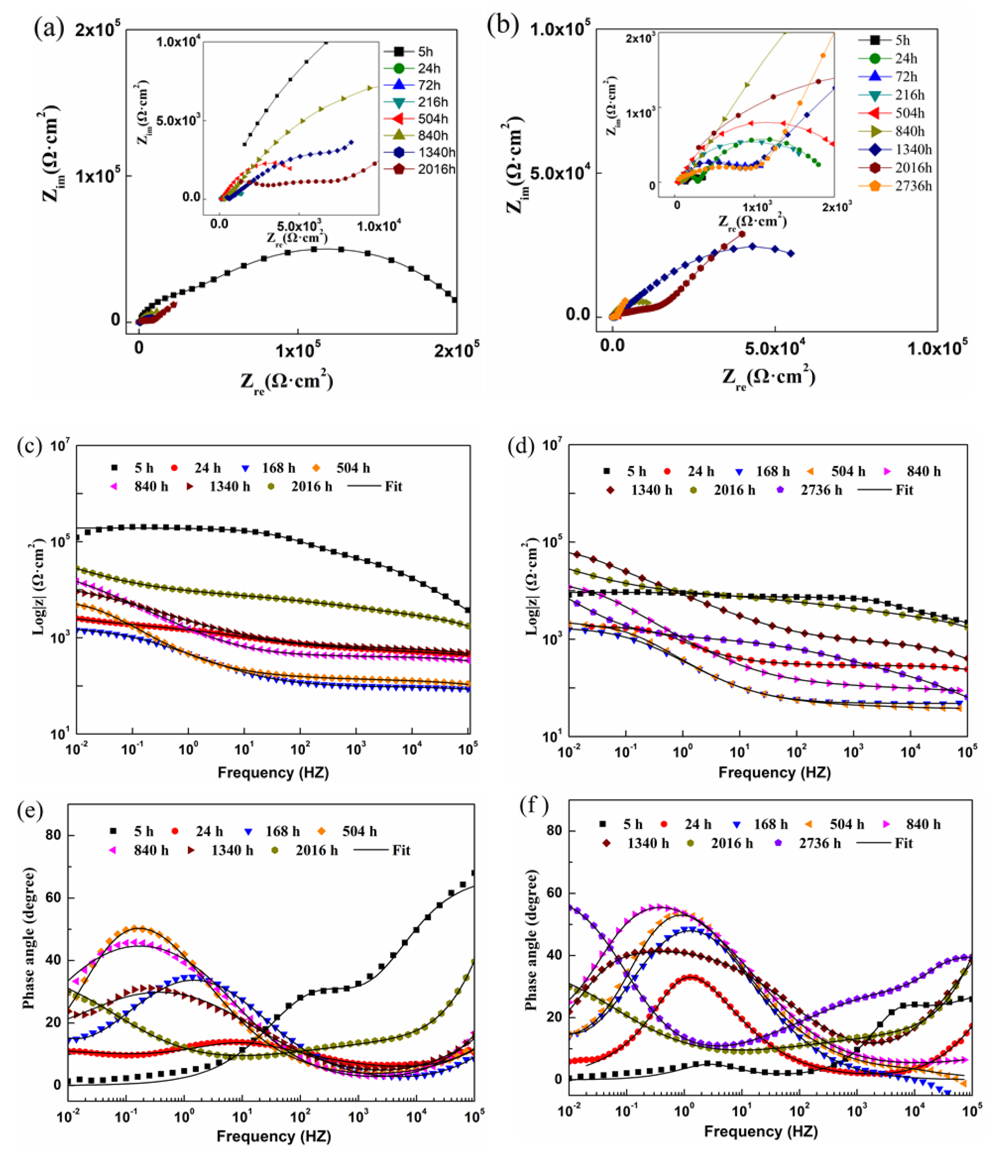
Nyquist of CGC and CPTES/CGC are presented in Figure 8a,b. Eight of EIS measurements data for CGC and CPTES/CGC were chosen as representatives to illustrate the impedance behavior in 3.5% NaCl solution: 5, 24, 168, 540, 840, 1340, 2016, and 2736 h. The symbol and solid line represent the experimental value and fitting value are presented in Figure 8c–f, respectively. For CGC, at an immersion time of 5 h, the semicircles in the low frequency domain showed a greater diameter and then decreased to a lower value. The phenomenon was similar to the decrease with log | Z | and the phase value of high frequency at a 5 h immersion time, which can be ascribed to the wetting and activation processes of zinc particles. Thereafter, same for CPTES/CGC, observation of the low frequency semicircles presents an increasing trend with immersion time and showed a second time constant, which was responsible for the poor barrier characteristics and the electrolyte solution can easily reach the coating/substrate interface due to the wettability of CPTES. According to [14,51], two semicircles were obtained for solvent-based zinc rich coatings; the first one is accounted to the impedance and capacitance of coating influenced by dielectric properties, the second one is related with impedance of the reaction of zinc dissolution and the capacitance of the double layer, attributed to the contact impedances that exist between the different zinc particles. Therefore, the diameter of the semicircles in the low frequency domain increased, indicating a decrease in the amount of the activated zinc particles, which slowed the consumption of zinc particles.
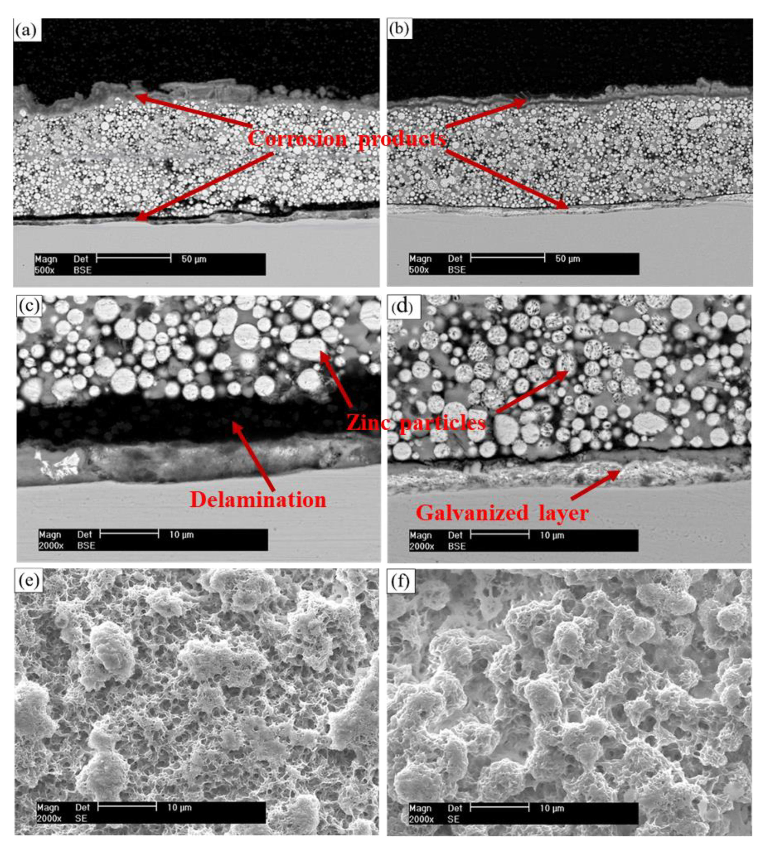
However, the corrosion protection properties of CGC were worse than CPTES/CGC, the results can be understood by the following reasons: (1) An interpenetrating network layer was formed within the coating by the acrylic resin polymer and CPTES, which contains silane monomer to form a siloxane network (Si–O–Si) and a crosslinking network was formed through dehydration condensation between hydroxyl at the resin end and silane. According to Liu [29], coatings with a higher polymer crosslinking density are expected to exhibit decreased water uptake and slower water diffusion. Compared to CGC, the surface of CPTES/CGC shows greater hydrophilicity as illustrated in Figure 1, but less pores and compacted coating make the inner-electrical connection between particles more sufficient. The amount of zinc particles that can provide more cathodic protection and less self-corrosion than CGC. (2) According to Chico [28,30], the Si–OH groups present in excess on the metallic surface condensed to form a siloxane network (Si–O–Si) of an appreciable thickness. Therefore, the adhesion mechanism of interpenetrating network seems to be the most important contributing factor to the adhesion and interfacial strength, which also strengthened the electrical connection between the zinc particles and the steel substrate. The detailed information of surface appearance and cross-section of the samples after immersion also provided evidence for our deduction. As shown in Figure 9, observation of Figure 9a,b both show the existence of two layers of corrosion products at the coating/solution and coating/substrate interfaces and the corrosion product was found at the inner part of CGC and CPTES/CGC. The observation of the surface topography from Figure 9e,f, which demonstrated that there are more zinc particles and less corrosion products on the surface of CPTES/CGC. Further observation from Figure 9c showed partial delamination between a coating and substrate in CGC, the galvanized layer completely consumed to provide cathodic protection to a steel substrate and zinc particles of CGC was almost consumed by self-corrosion. This can also explain why the OCP of CGC reached quickly to −0.78 V/SCE for 840 h. The CPTES/CGC micrograph in Figure 9d have shown that there were less corrosion products than in CGC at coating/substrate interfaces, the zinc particles were well connected to the HDG substrate, while zinc and galvanized layers frequently sacrificed themselves to protect the steel substrate. It can be predicted that the barrier effects in the later stage of the CPTES/CGC will be stronger than CGC, which was proved by the value of ZLF at the time of 1000–2000 h that is shown in Figure 7.

3.4.3. Equivalent Circuits Fitting and Fitting Parameters

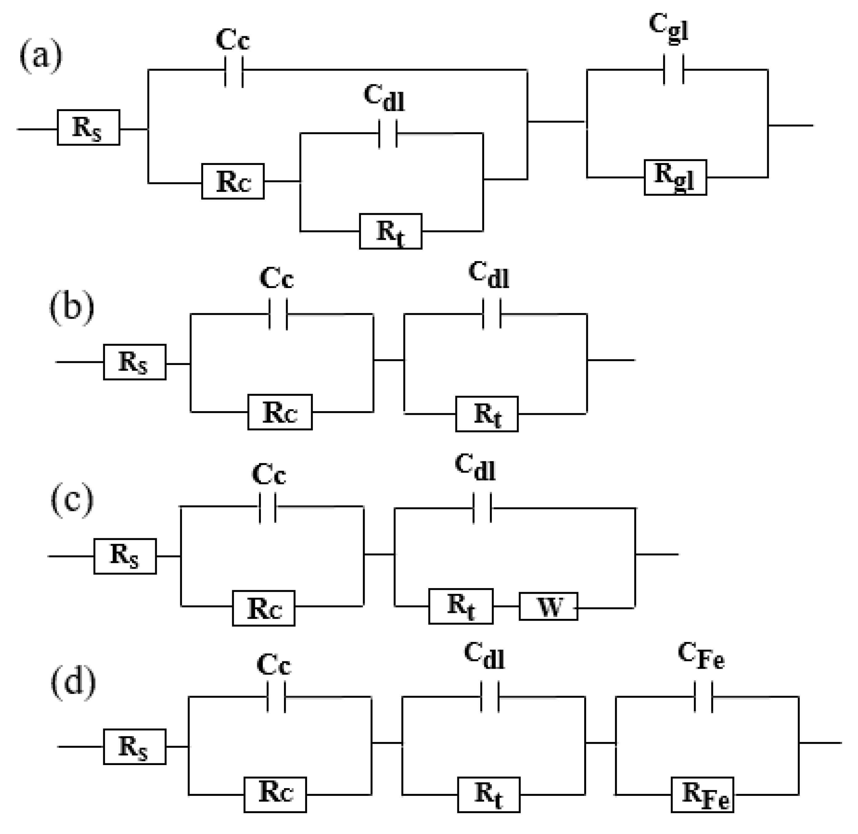
The equivalent circuits corresponding to the progress above were depicted in Figure 10. The phase diagram for CGC and CPTES/CGC were characterized by three peaks at the initial time (Figure 10a). As time elapsed, one peak that belong to the galvanized layer disappeared as shown by the equivalent circuit in Figure 10b, which was caused by the electrolyte solution that arrived at the coating/substrate interface through the pores of the coating, and zinc particles of the coating and galvanized layer had been activated completely. The cathodic protection effect provided by the coating and galvanized layer, confirmed by our observations in the cross-section picture (Figure 9). After that time, as the zinc particles were consumed, Warburg element appeared and the corrosion product gradually increased to hinder the transmission process by sealing the pores and flakes (Figure 10c). As the coating deteriorated severely, a third time constant appeared, which accounted for the corrosion of steel (Figure 10d). The elements include the resistances of the solution (Rs), coating (Rc), galvanized layer (Rgl), charge transfer (Rt), and Warburg diffusion (W). It also contains the constant phase elements representing the coating (Cc), galvanized layer (Cgl), and steel substrate (CFe). For CGC, after 840 h, Warburg diffusion behavior appeared with the products of cracks and delamination between coating/HDG substrate, and zinc particles had been consumed by self-corrosion quickly. As immersion time increases, the coating and galvanized layer became severely deteriorated and steel begins to corrode. For CPTES/CGC, the equivalent circuit was the same with that of CGC before 840 h, and afterwards, the coating system is at the stage of cathodic protection provided by zinc particles, and the equivalent was shown in Figure 10b.
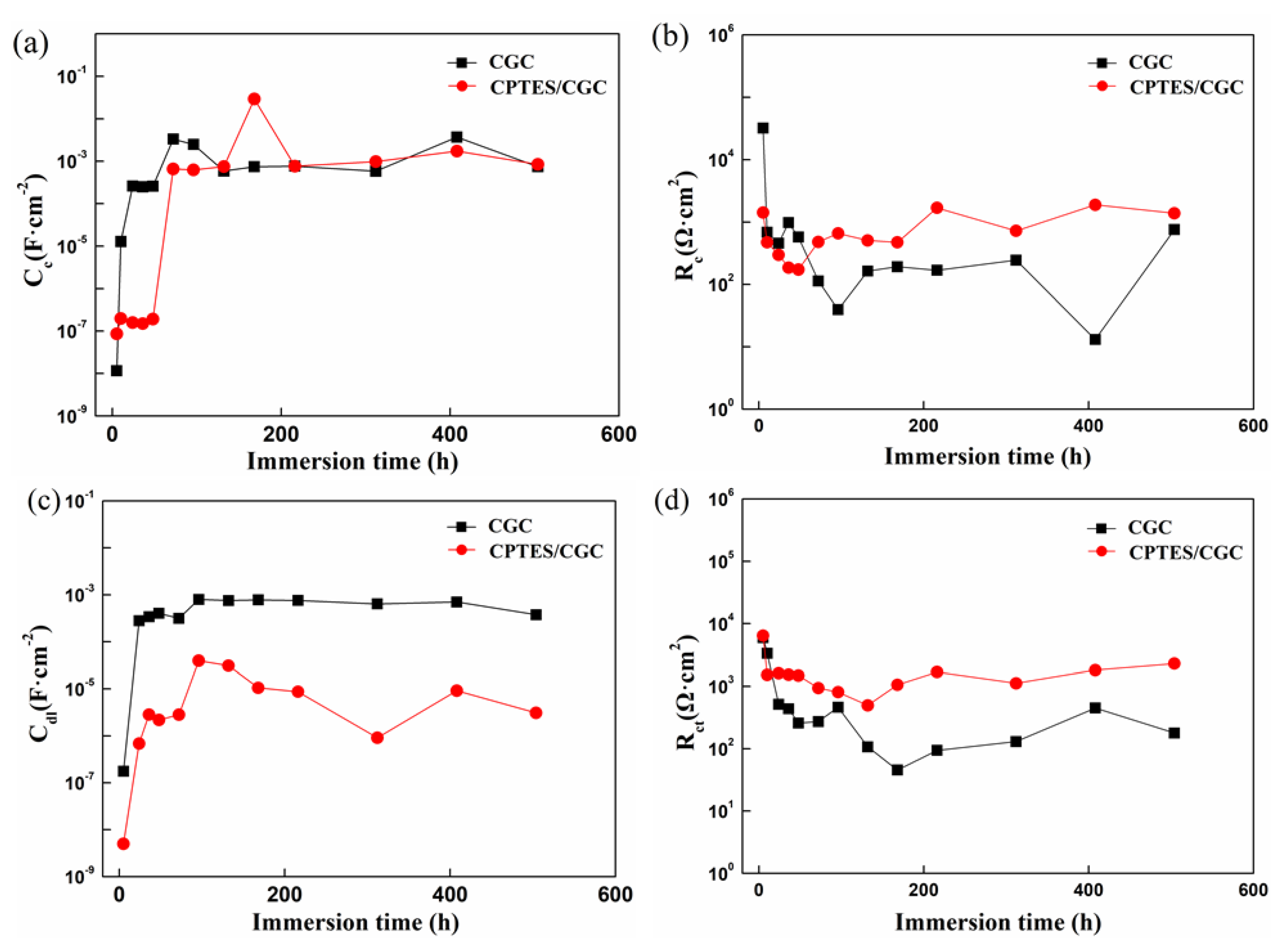
In corrosive environments, the electrolyte solution gradually permeates into the coating accompanied by decreasing coating resistance (Rc) and the increasing coating capacitance (Cc) [3]. The changes in Cc and Rc were attributed to the resistivity and dielectric constant of the electrolyte solution in the coating. The coating capacitance (Cc), in turn, relates closely to the electrolyte diffusion behavior in the coating, and Rc corresponds to the antipenetrating ability of coating. The logarithms of the coating capacitance and resistance with immersion time generated by fitting of the equivalent circuits were plotted in Figure 11.
It could be clearly observed from Figure 11a,b that all CGC and CPTES/CGC systems’ coatings capacitance Cc gradually increased and coatings resistance Rc gradually decreased at prolonged immersion time. The initial increases in coating resistance and decreases in coating capacitance were caused by water uptake into the coating. However, for CPTES/CGC, the coating capacitance Cc had a higher value than CGC at the initial stage due to poor hydrophobicity, and then rose to a platform lower than that of CGC. This behavior may be attributed to the low porosity caused by the cross-linking network, which showed that the water uptake of coatings decreased in a short amount of time after incorporation with silane monomer. Finally, the coating of 1.5% increased greatly and then maintained a relatively stable value, indicating that the homogeneity of the coatings decreased with the water uptake process.
Adhesion between the coating and the substrate can be reflected by the value of double layer capacitance Cdl [52]. According to Naderi [53], Cdl represents the amount of debonded area between the coating and substrate. According to Figure 11c, it can be seen that silane acted as an adhesion promoter when compared to that of CGC. In zinc-rich coatings, the charge transfer resistance (Rct) indicated the electrochemical activities of zinc particles rather than corrosion activities of the interface between the metal substrate and the coating [12]. Obviously, the Rct values (Figure 11d) of CPTES/CGC were higher than that of CGC because the contact area of zinc particles with the electrolyte was sufficiently large, which attributed to the delamination and cracks in CGC.

4. Conclusions

In this work, CPTES was innovatively incorporated into the coating to improve the adhesion and corrosion resistance of cold galvanizing coatings.
(1)
Water contact angle experimental results showed that wettability of the CPTES/CGC increase, compared with that of the CGC, which benefited to coating/substrate interface adhesion.
(2)
The FTIR and XPS results proved crosslinking networks occurred in the CPTES/CGC and its interface due to Si–O–Si, Si–O–C and Si–O–Zn bond formation.
(3)
The pull-off adhesion experimental results revealed that dry adhesion and wet adhesion of CPTES/CGC increase by 50% and 200%, respectively compared with CGC, attributed to wettability improvement and crosslinking network formation.
(4)
Electrochemical results indicated that the cathodic protection and barrier effects of CGC were improved by CPTES, especially the cathodic protection effect time increased threefold due to adhesion enhancement and three-dimensional network construction.

Author Contributions

Conceptualization, F.L.; formal analysis, Q.W., and W.Z.; investigation, J.L.; resources, E.-H.H.; data curation, N.G. and L.M.; writing—original draft preparation, J.L.; writing—review and editing, I.K.N.; supervision, F.L. All authors have read and agreed to the published version of the manuscript.

Funding

This research was funded by Shenyang Science and Technology Plan Project (Y17-1-039).

Institutional Review Board Statement

Not applicable.

Informed Consent Statement

Not applicable.

Data Availability Statement

Not applicable.

Conflicts of Interest

The authors declare no conflict of interest.

References

  1. Marder, A.R. The metallurgy of zinc-coated steel. Prog. Mater. Sci. 2000, 45, 191–271. [Google Scholar] [CrossRef]
  2. Li, C.; Liang, T.; Ma, R.; Du, A.; Fan, Y.; Zhao, X.; Cao, X. Superhydrophobic surface containing cerium salt and organosilane for corrosion protection of galvanized steel. J. Alloys Compd. 2020, 825, 153921. [Google Scholar] [CrossRef]
  3. Liu, Y.W.; Wang, Z.Y.; Cao, G.W.; Cao, Y.; Huo, Y. Study on corrosion behavior of zinc exposed in coastal-industrial atmospheric environment. Mater. Chem. Phys. 2017, 198, 243–249. [Google Scholar] [CrossRef]
  4. Cabral, A.M.; Trabelsi, W.; Serra, R.; Montemor, M.F.; Zheludkevich, M.L.; Ferreira, M.G.S. The corrosion resistance of hot dip galvanised steel and AA2024-T3 pre-treated with bis- triethoxysilylpropyl tetrasulfide solutions doped with Ce(NO3)3. Corros. Sci. 2006, 48, 3740–3758. [Google Scholar] [CrossRef]
  5. Zhu, D.Q.; van Ooij, W.J. Enhanced corrosion resistance of AA 2024-T3 and hot-dip galvanized steel using a mixture of bis- triethoxysilylpropyl tetrasulfide and bis- trimethoxysilylpropyl amine. Electrochim. Acta 2004, 49, 1113–1125. [Google Scholar] [CrossRef]
  6. Ramezanzadeh, B.; Attar, M.M. An evaluation of the corrosion resistance and adhesion properties of an epoxy-nanocomposite on a hot-dip galvanized steel (HDG) treated by different kinds of conversion coatings. Surf. Coat. Technol. 2011, 205, 4649–4657. [Google Scholar] [CrossRef]
  7. Lin, B.-L.; Lu, J.-T.; Kong, G. Effect of molybdate post-sealing on the corrosion resistance of zinc phosphate coatings on hot-dip galvanized steel. Corros. Sci. 2008, 50, 962–967. [Google Scholar] [CrossRef]
  8. Ramezanzadeh, B.; Attar, M.M. Studying the effects of micro and nano sized ZnO particles on the corrosion resistance and deterioration behavior of an epoxy-polyamide coating on hot-dip galvanized steel. Prog. Org. Coat. 2011, 71, 314–328. [Google Scholar] [CrossRef]
  9. Schaefer, K.; Miszczyk, A. Improvement of electrochemical action of zinc-rich paints by addition of nanoparticulate zinc. Corros. Sci. 2013, 66, 380–391. [Google Scholar] [CrossRef]
  10. Shreepathi, S.; Bajaj, P.; Mallik, B.P. Electrochemical impedance spectroscopy investigations of epoxy zinc rich coatings: Role of Zn content on corrosion protection mechanism. Electrochim. Acta 2010, 55, 5129–5134. [Google Scholar] [CrossRef]
  11. Xu, L.; Liu, F.; Han, E.-H.; Ke, W. Corrosion resistance and mechanism of one-component organic Zn15Al-rich coating. Prog. Org. Coat. 2019, 132, 305–315. [Google Scholar] [CrossRef]
  12. Yun, T.H.; Park, J.H.; Kim, J.-S.; Park, J.M. Effect of the surface modification of zinc powders with organosilanes on the corrosion resistance of a zinc pigmented organic coating. Prog. Org. Coat. 2014, 77, 1780–1788. [Google Scholar] [CrossRef]
  13. Bastos, A.C.; Zheludkevich, M.L.; Klüppel, I.; Grundmeier, G.; Ferreira, M.G.S. Modification of zinc powder to improve the corrosion resistance of weldable primers. Prog. Org. Coat. 2010, 69, 184–192. [Google Scholar] [CrossRef]
  14. Xu, L.; Liu, F.; Wang, Z.; Ke, W.; Han, E.-H.; Jie, G.; Wang, J.; Huang, H. The effect of surface modification of zinc particles with phosphoric acid on the corrosion resistance of cold galvanizing coatings. Prog. Org. Coat. 2018, 114, 90–101. [Google Scholar] [CrossRef]
  15. Xu, L.; Liu, F.; Liu, M.; Wang, Z.; Qian, Z.; Ke, W.; Han, E.-H.; Jie, G.; Wang, J.; Zhu, L. Fabrication of repairable superhydrophobic surface and improved anticorrosion performance based on zinc-rich coating. Prog. Org. Coat. 2019, 137, 105335. [Google Scholar] [CrossRef]
  16. Kalendová, A. Effects of particle sizes and shapes of zinc metal on the properties of anticorrosive coatings. Prog. Org. Coat. 2003, 46, 324–332. [Google Scholar] [CrossRef]
  17. Zhang, L.Y.; Ma, A.B.; Jiang, J.H.; Song, D.; Chen, J.Q.; Yang, D.H. Anti-corrosion performance of waterborne Zn-rich coating with modified silicon-based vehicle and lamellar Zn(Al) pigments. Prog. Nat. Sci. 2012, 22, 326–333. [Google Scholar] [CrossRef] [Green Version]
  18. Hare, C.H.; Kurnas, J.S. Reduced PVC and the design of metal primers. J. Coat. Technol. 2000, 72, 21–27. [Google Scholar] [CrossRef]
  19. Kalendova, A.; Kalenda, P.; Vesely, D. Comparison of the efficiency of inorganic nonmetal pigments with zinc powder in anticorrosion paints. Prog. Org. Coat. 2006, 57, 1–10. [Google Scholar] [CrossRef]
  20. Ramezanzadeh, B.; Moghadam, M.H.M.; Shohani, N.; Mandavian, M. Effects of highly crystalline and conductive polyaniline/graphene oxide composites on the corrosion protection performance of a zinc-rich epoxy coating. Chem. Eng. J. 2017, 320, 363–375. [Google Scholar] [CrossRef]
  21. Arman, S.Y.; Ramezanzadeh, B.; Farghadani, S.; Mehdipour, M.; Rajabi, A. Application of the electrochemical noise to investigate the corrosion resistance of an epoxy zinc-rich coating loaded with lamellar aluminum and micaceous iron oxide particles. Corros. Sci. 2013, 77, 118–127. [Google Scholar] [CrossRef]
  22. Cho, S.; Chiu, T.M.; Castaneda, H. Electrical and electrochemical behavior of a zinc-rich epoxy coating system with carbon nanotubes as a diode-like material. Electrochim. Acta 2019, 316, 189–201. [Google Scholar] [CrossRef]
  23. Feliu, S.; Morcillo, M.; Feliu, S. Deterioration of cathodic protection action of zinc-rich paint coatings in atmospheric exposure. Corrosion 2001, 57, 591–597. [Google Scholar] [CrossRef]
  24. Fedel, M.; Olivier, M.; Poelman, M.; Deflorian, F.; Rossi, S.; Druart, M.E. Corrosion protection properties of silane pre-treated powder coated galvanized steel. Prog. Org. Coat. 2009, 66, 118–128. [Google Scholar] [CrossRef]
  25. Pourhashem, S.; Vaezi, M.R.; Rashidi, A.; Bagherzadeh, M.R. Distinctive roles of silane coupling agents on the corrosion inhibition performance of graphene oxide in epoxy coatings. Prog. Org. Coat. 2017, 111, 47–56. [Google Scholar] [CrossRef]
  26. Jiang, M.Y.; Wu, L.K.; Hu, J.M.; Zhang, J.Q. Silane-incorporated epoxy coatings on aluminum alloy (AA2024). Part 1: Improved corrosion performance. Corros. Sci. 2015, 92, 118–126. [Google Scholar] [CrossRef]
  27. Iglesias, J.G.; Gonzalez-Benito, J.; Aznar, A.J.; Bravo, J.; Baselga, J. Effect of glass fiber surface treatments on mechanical strength of epoxy based composite materials. J. Colloid Interface Sci. 2002, 250, 251–260. [Google Scholar] [CrossRef] [Green Version]
  28. Davis, S.R.; Brough, A.R.; Atkinson, A. Formation of silica/epoxy hybrid network polymers. J. Non Cryst. Solids 2003, 315, 197–205. [Google Scholar] [CrossRef]
  29. Liu, B.; Fang, Z.G.; Wang, H.B.; Wang, T. Effect of cross linking degree and adhesion force on the anti-corrosion performance of epoxy coatings under simulated deep sea environment. Prog. Org. Coat. 2013, 76, 1814–1818. [Google Scholar] [CrossRef]
  30. Chico, B.; Galván, J.C.; de la Fuente, D.; Morcillo, M. Electrochemical impedance spectroscopy study of the effect of curing time on the early barrier properties of silane systems applied on steel substrates. Prog. Org. Coat. 2007, 60, 45–53. [Google Scholar] [CrossRef]
  31. Ji, W.-G.; Hu, J.-M.; Zhang, J.-Q.; Cao, C.-N. Reducing the water absorption in epoxy coatings by silane monomer incorporation. Corros. Sci. 2006, 48, 3731–3739. [Google Scholar] [CrossRef]
  32. Ji, W.-G.; Hu, J.-M.; Liu, L.; Zhang, J.-Q.; Cao, C.-N. Water uptake of epoxy coatings modified with γ-APS silane monomer. Prog. Org. Coat. 2006, 57, 439–443. [Google Scholar] [CrossRef]
  33. Wang, P.; Schaefer, D.W. Why does Silane Enhance the Protective Properties of Epoxy Films? Langmuir 2008, 24, 13496–13501. [Google Scholar] [CrossRef] [PubMed]
  34. Montemor, M.F.; Cabral, A.M.; Zheludkevich, M.L.; Ferreira, M.G.S. The corrosion resistance of hot dip galvanized steel pretreated with Bis-functional silanes modified with microsilica. Surf. Coat. Technol. 2006, 200, 2875–2885. [Google Scholar] [CrossRef]
  35. ISO 4624: 2016 Paints and Varnishes— Pull-off Test for Adhesion; ISO: Geneve, Switzerland, 2016.
  36. Zhang, D.; Qian, H.; Wang, L.; Li, X. Comparison of barrier properties for a superhydrophobic epoxy coating under different simulated corrosion environments. Corros. Sci. 2016, 103, 230–241. [Google Scholar] [CrossRef]
  37. Wang, X.; Hu, J.; Li, Y.; Zhang, J.; Ding, Y. The surface properties and corrosion resistance of fluorinated polyurethane coatings. J. Fluor. Chem. 2015, 176, 14–19. [Google Scholar] [CrossRef]
  38. Chibowski, E.; Perea-Carpio, R. Problems of contact angle and solid surface free energy determination. Adv. Colloid Interface Sci. 2002, 98, 245–264. [Google Scholar] [CrossRef]
  39. Li, D.; Neumann, A.W. Contact angles on hydrophobic solid surfaces and their interpretation. J. Colloid Interface Sci. 1992, 148, 190–200. [Google Scholar] [CrossRef]
  40. Vakili, H.; Ramezanzadeh, B.; Amini, R. The corrosion performance and adhesion properties of the epoxy coating applied on the steel substrates treated by cerium-based conversion coatings. Corros. Sci. 2015, 94, 466–475. [Google Scholar] [CrossRef]
  41. Rodic, P.; Iskra, J.; Milosev, I. A hybrid organic-inorganic sol-gel coating for protecting aluminium alloy 7075-T6 against corrosion in Harrison’ s solution. J. Sol Gel Sci. Technol. 2014, 70, 90–103. [Google Scholar] [CrossRef]
  42. Rodic, P.; Korosec, R.C.; Kapun, B.; Mertelj, A.; Milosev, I. Acrylate-Based Hybrid Sol-Gel Coating for Corrosion Protection of AA7075-T6 in Aircraft Applications: The Effect of Copolymerization Time. Polymers 2020, 12, 948. [Google Scholar] [CrossRef] [PubMed] [Green Version]
  43. Jiao, C.; Shao, Q.; Wu, M.; Zheng, B.; Guo, Z.; Yi, J.; Zhang, J.; Lin, J.; Wu, S.; Dong, M.; et al. 2-(3,4-Epoxy) ethyltriethoxysilane-modified waterborne acrylic resin: Preparation and property analysis. Polymer 2020, 190, 122196. [Google Scholar] [CrossRef]
  44. Wu, G.; Ma, L.; Jiang, H. The roles of surface wettability and roughness of carbon fibers in interfacial enhancement of silicone resin composites. Polym. Compos. 2019, 40, E255–E264. [Google Scholar] [CrossRef]
  45. Rodič, P.; Kapun, B.; Panjan, M.; Milošev, I. Easy and Fast Fabrication of Self-Cleaning and Anti-Icing Perfluoroalkyl Silane Film on Aluminium. Coatings 2020, 10, 234. [Google Scholar] [CrossRef] [Green Version]
  46. NIST X-ray Photoelectron Spectroscopy Database. NIST Standard Reference Database Number 20; National Institute of Standards and Technology: Gaithersburg, MD, USA, 2000; Volume 2000. [CrossRef]
  47. Uzoma, P.C.; Liu, F.; Xu, L.; Zhang, Z.; Han, E.-H.; Ke, W.; Arukalam, I.O. Superhydrophobicity, conductivity and anticorrosion of robust siloxane-acrylic coatings modified with graphene nanosheets. Prog. Org. Coat. 2019, 127, 239–251. [Google Scholar] [CrossRef]
  48. Meroufel, A.; Touzain, S. EIS characterisation of new zinc-rich powder coatings. Prog. Org. Coat. 2007, 59, 197–205. [Google Scholar] [CrossRef]
  49. Abreu, C.M.; Izquierdo, M.; Keddam, M.; Nóvoa, X.R.; Takenouti, H. Electrochemical behaviour of zinc-rich epoxy paints in 3% NaCl solution. Electrochim. Acta 1996, 41, 2405–2415. [Google Scholar] [CrossRef]
  50. Bonnel, K.; Le Pen, C.; Pébère, N.E.I.S. characterization of protective coatings on aluminum alloys. Electrochim. Acta 1999, 44, 4259–4267. [Google Scholar] [CrossRef]
  51. Marchebois, H.; Keddam, M.; Savall, C.; Bernard, J.; Touzain, S. Zinc-rich powder coatings characterisation in artificial sea water: EIS analysis of the galvanic action. Electrochim. Acta 2004, 49, 1719–1729. [Google Scholar] [CrossRef]
  52. Armstrong, R.D.; Wright, J.D. Impedance studies of poly ethylmethacrylate coatings formed upon tin-free steel. Corros. Sci. 1992, 33, 1529–1539. [Google Scholar] [CrossRef]
  53. Naderi, R.; Attar, M.M.; Moayed, M.H. EIS examination of mill scale on mild steel with polyester-epoxy powder coating. Prog. Org. Coat. 2004, 50, 162–165. [Google Scholar] [CrossRef]
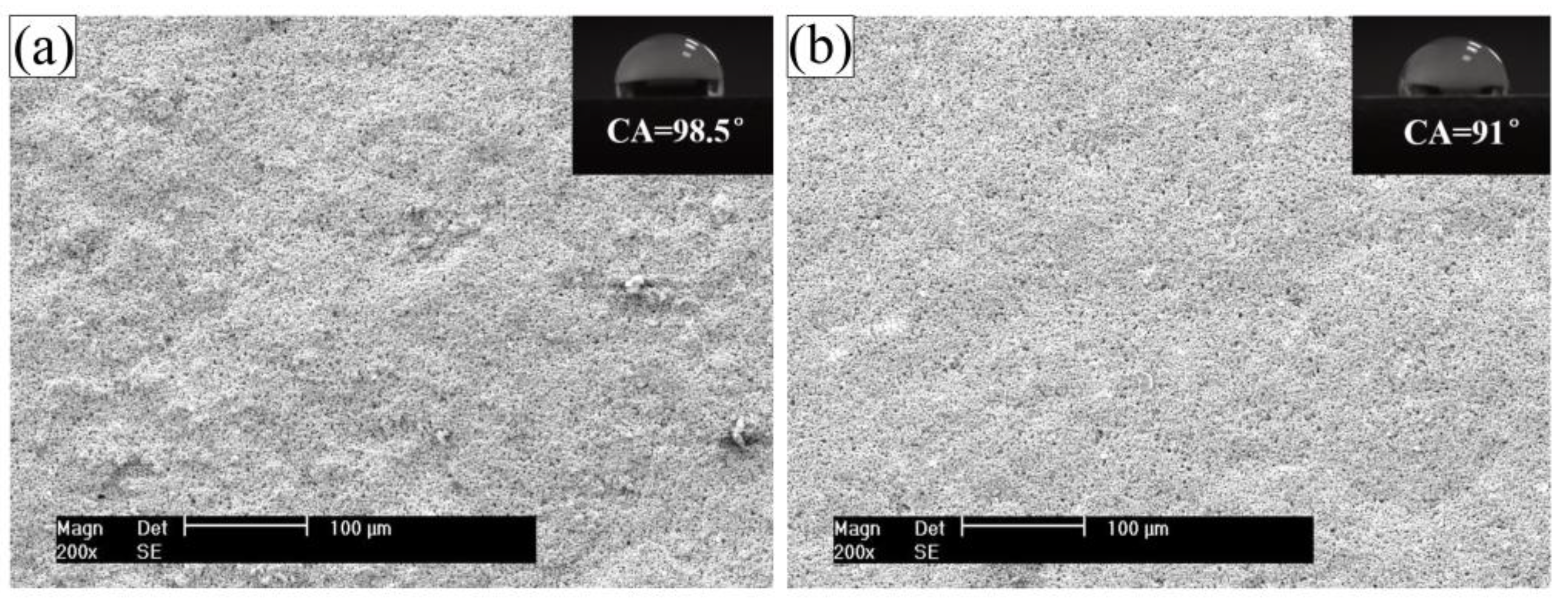
Figure 1. SEM images of the surface morphologies of coatings, (a): CGC and (b): CPTES/CGC. Inserts are the images of the water droplets on the corresponding coatings.
Coatings 11 00402 g001
Figure 2. FTIR spectra of coating surfaces.
Coatings 11 00402 g002
Figure 3. XPS spectra of CGC (a): C 1s and (b): O 2s and CPTES/CGC (c): C 1s, (d): O 2s, (e): Si 2p, and (f): Cl 2p.
Coatings 11 00402 g003
Figure 4. Digital photographs after the dry adhesion tests on, CGC (a) and CPTES/CGC (b) and the wet adhesion tests on, CGC (c) and CPTES/CGC (d) after 20 days of immersion in 3.5 wt % NaCl.
Coatings 11 00402 g004
Figure 5. Schematic illustration of the mechanism of (a): silane hydrolysis, (b): grafted reaction between silanol and resin, and (c): bonding reaction between silanol and HDG substrate.
Coatings 11 00402 g005
Figure 6. Electrochemical tests in 3.5 wt % NaCl solution for CGC and CPTES/CGC. (a): open circuit potential and (b): potentiodynamic polarization curves.
Coatings 11 00402 g006
Figure 7. The evolutions of the low frequency impedance modulus ZLF with immersion time for coatings.
Coatings 11 00402 g007
Figure 8. Electrochemical impedance spectroscopy (EIS) spectra of coatings after immersion in 3.5 wt % NaCl solution for different times. (a,c,e): CGC and (b,d,f): CPTES/CGC.
Coatings 11 00402 g008
Figure 9. The cross-section SEM micrograph of the coatings after immersion in 3.5 wt % NaCl solution for 20 days: (a,c): CGC and (b,d): CPTES/CGC; and surface topography SEM micrograph of the coatings after immersion in 3.5 wt % NaCl solution for 20 days: (e): CGC and (f): CPTES/CGC.
Coatings 11 00402 g009
Figure 10. The corresponding equivalent circuits for electrochemical behavior of CGC and CPTES/CGC in different time; (a): 0–24 h for CGC, 0–72 h for CPTES/CGC; (b):24–504 h for CGC, 72–2736 h for CPTES/CGC; (c): 504–840 h for CGC, after 2736 h for CPTES/CGC; and (d): after 840 h for CGC.
Coatings 11 00402 g010
Figure 11. Evolution of (a) coatings capacitance, (b) charge transfer resistance, (c) double layer capacitance, and (d) charge transfer resistance with immersion time.
Coatings 11 00402 g011
Table 1. Formulation of cold galvanizing coatings.
SamplesZinc Powders (wt %)Resin (wt %)Solvent (wt %)Silane (wt %)
CGC69.517.413.1
CPTES/CGC69.517.411.12
Table 2. Water contact angle, work of adhesion, and surface free energy values measured on the surface of coatings.
Sample θ   ( ° ) Wa ( μ J / cm 2 ) γ sv ( μ J / cm 2 )
CGC98.5 ± 0.876.20 ± 0.112.40 ± 0.06
CPTES/CGC91.0 ± 0.717.15 ± 0.092.86 ± 0.04
Table 3. Dry and wet adhesion strength of CGC and CPTES/CGC.
SamplesDry Adhesion (MPa)Modality of FailureWet Adhesion (MPa)Modality of FailureAdhesion Loss
CGC2.0 (2.28 ± 0.12)50% A/B, 50% B1.0 (1.12 ± 0.28)90% A/B, 10% B50.9%
CPTES/CGC3.0 (3.36 ± 0.44)100% B3.0 (2.64 ± 0.24)10% A/B, 90% B21.4%
Table 4. Corrosion potentials, corrosion current densities, Tafel constants and polarization resistance values obtained via the Tafel fit of the polarization scan.
SamplesIcorr (A/cm2)Ecorr (V/SCE)Ba (mV)Bc (mV)Rp ( Ω · cm2)
CGC8.59 × 10−5 (± 1.04 × 10⁻⁵)−0.98 (± 0.0055)274.18 (± 15.65)−465.49 (± 31.33)3.41 × 10³ (± 154.0)
CPTES/CGC1.55 × 10−6 (± 1.625 × 10⁻⁷)−0.85 (± 0.014)256.53 (± 32.10)−331.32 (± 60.90)4.74 × 10⁵ (± 3.16 × 10⁵)
Publisher’s Note: MDPI stays neutral with regard to jurisdictional claims in published maps and institutional affiliations.