Abstract
The bond coat of a NiCrAlY thermal barrier coating plays an important role in solving the thermal expansion mismatch between a metal matrix and a ceramic layer and in improving the oxidation resistance of the whole thermal barrier coating. However, the NiCrAlY bond coat prepared by low-pressure plasma spraying is not conducive to its oxidation resistance because its lamellar structure is loose, porous and the surface is rough. To improve the oxidation resistance of the bond coat, the NiCrAlY bond coat prepared by plasma spraying was modified by high-current pulsed electron beam with different energy densities. Under the electron beam irradiation, the surface of the coating became smooth, and there was a 3–5 μm thick remelting layer on the surface. Under the irradiation, the thickness of the thermal growth oxide layer decreased, and the oxidation resistance was significantly improved, the oxidation product being mainly Al2O3.
1. Introduction
With the development of aerospace technology, the service temperature of hot-end components, such as engine turbine blades, is getting higher. Adding thermal barrier coating (TBCs) is one of the effective methods to improve the resistance to elevated temperatures of the engine. The thermal barrier coating system consists of a superalloy substrate, a ceramic layer, a bond coat and a thermal growth oxide (TGO) layer between the ceramic layer and the bond coat. The role of the bond coat is to solve the thermal expansion mismatch between the metal matrix and the ceramic layer and to improve the oxidation resistance of the entire coating. The thermal barrier coatings have a development history of nearly 40 years, and their preparation process is constantly improving. From the initial atmospheric plasma spraying (APS), to low-pressure plasma spraying (LPPS), in addition to high velocity oxy-fuel spraying (HOVF), laser cladding, electron beam physical vapor deposition (EB-PVD) and other methods [1,2,3,4,5,6,7]. The bond coat of thermal barrier coatings prepared by atmospheric pressure and low-pressure plasma spraying methods has a lamellar structure, which is conducive to the improvement of thermal insulation performance of thermal barrier coatings. It has also the advantages of rapid and cheap coating preparation process, so it has a wide application prospect [8,9,10,11].
However, the coating prepared by plasma spraying technology has also its disadvantages. First, the lamellar structure, loose and porous, of the thermal barrier coating prepared by this method, can easily lead to the coating falling off during service, despite improving the thermal insulation performance of the coating. Second, the surface roughness of the bond coat prepared by this method is relatively large, which makes the interface between the bond coat and the ceramic layer uneven. This may easily cause an uneven growth of the TGO layer, leading to the degradation of the oxidation resistance of the coating. To improve the oxidation resistance of the NiCrAlY bond coat and the porous structure of the coating, the energy beam irradiation can be used to reduce the surface roughness, while the high-current pulsed electron beam technology is a good choice [12,13,14,15].
The interaction between high-current pulsed electron beam and the material surface is a process of rapid heating and rapid cooling, the heating rate is as high as 109 K/s, and the material surface can be heated to melt instantaneously at a certain depth. The formed maximum temperature gradient (107–8 K/m) can make the surface layer cool sharply under the heat conduction to the matrix, and the cooling rate can also reach 104–9 K/s. Thus, the surface of solid materials remelts to improve the surface properties of materials [16]. Compared with laser beam and pulsed ion beam, high-current pulsed electron beam technology has a high degree of monitoring and adjustment of the injected energy, which is conducive to a high degree of local energy distribution and a high effective action coefficient. Moreover, the high-current pulsed electron beam irradiation is a pure energy transport process, which overcomes the impact of ion impurity on the material during the ion beam irradiation; the depth of the modified layer is much larger than that of the high intensity pulsed ion beam, and its energy utilization rate is much higher than that of the laser beam [17,18,19,20,21].
In this paper, the NiCrAlY bond coat prepared by low-pressure plasma spraying was irradiated by high-current pulsed electron beam, and the effects of electron beam irradiation on the structure and oxidation resistance of the coating were studied.
2. Numerical and Experimental Methods
The temperature evolution of NiCrAlY coating with time and space under high-current pulsed electron beam irradiation was simulated by the Finite element method.
The matrix of DZ4 nickel-based superalloy was cut into samples with a dimension of 14 mm × 14 mm × 2.0 mm. The samples were pre-grinded, polished and roughed, and the NiCrAlY bond coat was prepared by low-pressure plasma spraying device (Beijing Aeronautical Manufacturing Technology Research Institute, Beijing, China) on the sample. Table 1 shows the composition of this coating. The bond coat was irradiated with a high-current pulsed electron beam, the width of pulse was 200 μs, the energy densities were 12, 15, 18 J/cm2, and the number of pulses was five. The high-current pulsed electron beam irradiation was performed on the SOLO device (Institute of High Current Electronics of the Siberian Branch of the Russian Academy of Sciences, Tomsk, Russia).

Table 1.
The composition elements of the coating and corresponding atomic percentages.
The NiCrAlY bond layers on the samples treated by high-current pulsed electron beam were subjected to static oxidation at 900 °C for 200 h and taken out for weighing every 10 h. The structural changes of NiCrAlY bond layers before and after electron beam irradiation were analyzed by scanning electron microscope (SEM) (JSM-5600LV, JEOL Ltd., Akishima, Japan) and X-ray diffractometer (XRD) (XRD-6000, Shimadzu, Kyoto, Japan). The effects of the high-current pulsed electron beam irradiation on the oxidation resistance of the NiCrAlY bond layer were analyzed based on the oxidation kinetics curve.
3. Results and Discussions
3.1. Computational Temporal and Spatial Evolution of the Temperature Field of the NiCrAlY Coating Irradiated by a High-Current Pulsed Electron Beam
The finite element method [22] was used to simulate the temperature evolution of the NiCrAlY coating in time and space under a high-current pulsed electron beam irradiation. According to the law of conservation of energy, the temperature T(x,t) field can be expressed as:
Here, ρ is density, C(T) is specific heat, λ is thermal conductivity. Li and Ti are latent heat and temperature of fusion or evaporation, respectively. P is the heat source term:
where k is the energy density, d(x) and f(t) are normalized functions, respectively describing the distribution of electron beam energy in space and time. d(x) and f(t) are determined by electron range r (cm) and pulse width τ (μs), respectively. The electron range r is related to the acceleration voltage U (V) and ρ coating density (g/cm3):
The specific heat capacity and thermal conductivity of the NiCrAlY coating were obtained from literature [23,24]. Melting and boiling points were 1629 K and 2982 K, respectively. The initial condition was T(x,0) = 298 K and the boundary condition was adiabatic. The latent heats of fusion and evaporation of the NiCrAlY layer were weighted averages of its constituent elements.
Figure 1 shows the temperature evolution of the NiCrAlY coating in time and space under the high-current pulsed electron beam irradiation with the energy density of 12, 15 and 18 J/cm2, simulated by the finite element method. The maximum temperature (Tmax) of the coatings under irradiation of 12, 15 and 18 J/cm2 increased with the energy density, in each case exceeding the melting point. The melting depth of the coatings at these three energy densities was 3.8, 5.3 and 6.6 μm, respectively. During the irradiation of 15 J/cm2, due to the latent heat of evaporation, although the coating was continuously heated by the electron beam, its Tmax did not exceed the boiling point. The Tmax of the coating was maintained at a temperature near the boiling point for more than 100 μs (red arrow in Figure 1b). When the energy density reached 18 J/cm2, the higher energy density enabled the coating to complete the evaporative phase transition, and the Tmax of the coating exceeded the boiling point.
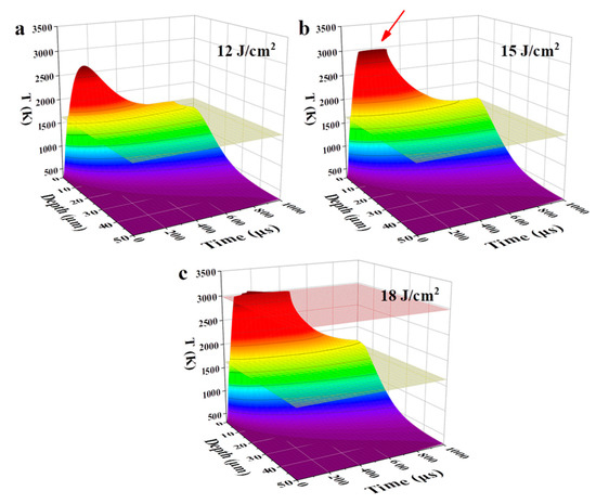
Figure 1.
Temporal and spatial evolution of a temperature field, simulated by the finite element method, of the NiCrAlY bond coat irradiated by a high-current pulsed electron beam with different energy densities: (a) 12 J/cm2, (b) 15 J/cm2, (c) 18 J/cm2. The yellow and red planes indicate the melting and boiling temperatures, respectively. The red arrow in (b) points to the Tmax of the coating.
3.2. Influence of a High-Current Pulsed Electron Beam Irradiation on the Micro-Morphology and Structure of the NiCrAlY Bond Coat
Figure 2 shows the surface morphological SEM image of the NiCrAlY bond coat prepared by the low-pressure plasma spraying method before and after irradiation by a high-current pulsed electron beam. The surface of the original coating was lamellate and loose with many holes and cracks (depicted by the arrows in Figure 2a). The principle of NiCrAlY coating by low-pressure plasma spraying is that the molten coating components are ejected with high-speed plasma jet and deposited on the surface of the substrate to form a lamellar coating. The lamellar structure of the coating is relatively loose. At the same time, due to the high spraying temperature of the coating, stress occurs during cooling, leading to the existence of cracks and holes on the surface of the coating. Oxygen can enter along these pores and voids, accelerating the oxidation of the coating and shortening its service life. After the high-current pulsed electron beam irradiation with an energy density of 12 J/cm2 (Figure 2b), the surface of the NiCrAlY bond coat partially remelted.
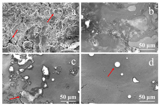
Figure 2.
Surface morphology of the NiCrAlY bond coat before and after a high-current pulsed electron beam irradiation: (a) nonirradiated, the arrows point to the holes and cracks (b) 12 J/cm2; (c) 15 J/cm2, the arrow points to a crack; (d) 18 J/cm2, the arrow points to a circular granular structure.
According to the calculated temperature field, the thickness of the remelted layer increased with the increase in energy density; thus, the surface became more and more flat. Especially when the energy density reached 18 J/cm2 and the maximum temperature of the coating exceeded the boiling point, the evaporation of coating elements accelerated the mass flow of the molten layer, the loose porous structure disappeared, and the surface became flat. Meanwhile, circular granular structures with different sizes appeared. According to electron probe micro-analysis (EPMA) (EPMA-1600, Shimadzu, Kyoto, Japan) analysis, the major components in the large bulge (as shown by the arrow in Figure 2d) were Al, Y and O. In the process of electron beam irradiation, the low melting point component of the coating evaporated first and erupted to the surface. O was introduced by the preparation process and pollution of the coating. As can be seen from the area pointed by the arrow in Figure 2c, after the irradiation of 15 J/cm2, the surface bulges were separated by cracks, indicating that the cracks formed behind the protrusions. When the coating was remelted by pulsed electron beam, bulges were formed on the surface of the coating. After the irradiation, the temperature of the coating surface dropped sharply, and cracks formed when the surface stress exceeded the material strength, resulting in the morphology of the coating bulges separated by cracks. The irradiation by the high-current pulsed electron beam made the surface of the NiCrAlY coating smooth and almost without pores. The reduction in the surface roughness of the coating may affect the bonding properties of the ceramic layer, which is a limitation of this technique, but the life of thermal barrier coating (TBC) can be extended by reducing the thickness of the thermal grown oxide layer and improving the oxidation resistance [13,25,26].
The cross-section morphology of the NiCrAlY coating irradiated by a high-current pulsed electron beam with a pulse width of 200 μs and energy density of 18 J/cm2 is shown in Figure 3. A clear boundary can be seen between the remelted layer and the original coating, depicted by the dashed line in the figure, and the remelting layer had a thickness of about 3–5 μm, a dense structure and lacked holes. The structure of the area below the remelting layer was relatively loose, with many holes. The NiCrAlY coating formed by a low-pressure plasma spraying had a loose structure, and there were many pores inside the coating, while the high temperature caused by the electron beam bombardment of the sample enabled the coating surface to remelt (Figure 2b–d). In a high-temperature environment, the dense remelting layer can prevent oxygen from entering the interior of the coating. In a thermal barrier coating system, the thickness of the TGO layer can be reduced to decrease the stress in the coating, thus prolonging the service life of the coating [14,27]. The thickness of the remelted layer was lower than the theoretical calculated value because the temperature of the NiCrAlY coating reached the boiling point when the energy density was up to 18 J/cm2, and the influence of mass loss could not be considered in the temperature field calculated by the finite element method; therefore, the theoretical calculated value was higher than the measured remelted layer thickness.
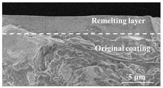
Figure 3.
Cross-sectional morphology of the NiCrAlY coating irradiated by a high-current pulsed electron beam with an energy density of 18 J/cm2.
Figure 4 presents the XRD pattern of the NiCrAlY bond layer before and after the high-current pulsed electron beam irradiation. The original NiCrAlY bond coat was mainly composed of γ/γ′ phase and β phase (Figure 4a). However, after the irradiation, the phase structure of the coating changed, the ratio of the β-NiAl phase decreased or the preferred orientation of (200) for the γ/γ′ phase occurred. Since the peak positions of (110) plane for the β-NiAl phase and (111) plane for the γ/γ′ phase are close to each other, it was impossible to distinguish them. There are many reasons for the change of the phase, but it must be related to the preferred orientation during the rapid non-equilibrium solidification of the surface remelting layer in the electron beam energy injection.
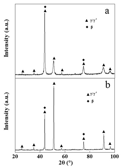
Figure 4.
XRD patterns of the NiCrAlY bond coat before and after a high-current pulsed electron beam irradiation: (a) nonirradiated coating, (b) 18 J/cm2. a.u.—arbitrary units.
The diffraction peak position of the coating did not move significantly after the irradiation (Figure 4). Irradiated by a high-current pulsed electron beam, a coating is rapidly heated to extremely high temperatures and then rapidly cooled. During the cooling process, a large temperature gradient occurs near the surface of the coating, resulting in a residual microscopic internal stress in the coating, which leads to the XRD peak shift. The reason why the diffraction peak did not significantly shift (as can be seen in Figure 4) might be that the NiCrAlY coating prepared by the low-pressure plasma spraying process had a loose lamellar structure, which could effectively relieve the stress caused by the electron beam irradiation. A small number of cracks in the coating was also conducive to the release of stress. The reduction of residual internal stress in the coating could reduce the crack on the surface and was helpful to improve the service life of the coating.
3.3. Effect of a High-Current Pulsed Electron Beam Irradiation on the Oxidation Resistance of the NiCrAlY Bond Coat
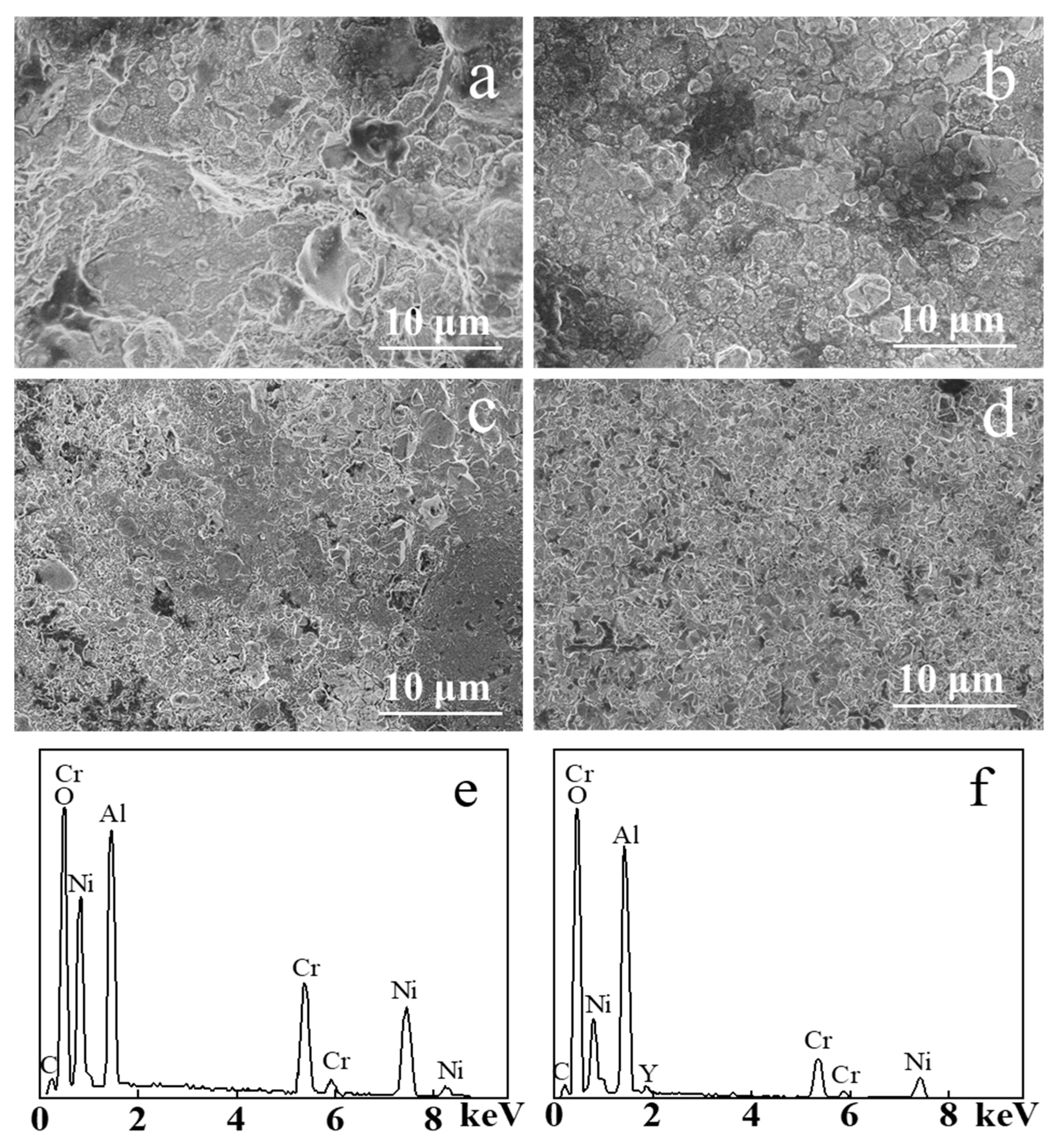
Figure 5 shows the SEM image of the samples before and after electron beam irradiation after static oxidation at 900 ℃ for 100 h. TGO formed on the NiCrAlY coating surface after the 100 h static oxidation made its surface more uneven (Figure 5a). The surface of the original coating was loose and porous before oxidation, and the surface area of the coating was larger than that of the coating irradiated by the electron beam. As a result, the oxidized area was larger in the static oxidation process, thus the TGO was generated unevenly, and the oxide grain size reached more than 10 μm. After 100 h of static high temperature oxidation, the TGO generated on the NiCrAlY coating surface irradiated by a high-current pulsed electron beam with different energy densities (Figure 5b–d) was relatively smooth, and the oxide formed was relatively dense. The oxide size was reduced to a few μm after the electron beam irradiation of 12 J/cm2 (Figure 5b). The size of the oxide on NiCrAlY coating decreased with the increase in energy density. When the energy density was 18 J/cm2 (Figure 5d), the grain size of oxides was reduced to less than 1 μm and the size was uniform. It can be concluded that after a 100 h static oxidation, on the surface of the coating, a layer of a dense oxide formed, which could prevent oxygen from further oxidation reaction with the coating. Figure 5e shows the result of the energy dispersive X-ray spectroscopy (EDS) composition analysis after static oxidation of the nonirradiated coating, and the corresponding result of the 18 J/cm2 irradiated coating is shown in Figure 5f. It is evident that both coatings contained many oxides of Al, whereas, compared with the coatings after irradiation, the untreated coatings contained relatively more oxides of Ni and Cr.

Figure 5.
SEM images of the NiCrAlY coating surface morphology before and after a high-current pulsed electron beam irradiation after static oxidation at 900 ℃ for 100 h: (a) nonirradiated, (b) 12 J/cm2, (c) 15 J/cm2, (d) 18 J/cm2, (e,f) the EDS results of (a,d), respectively.
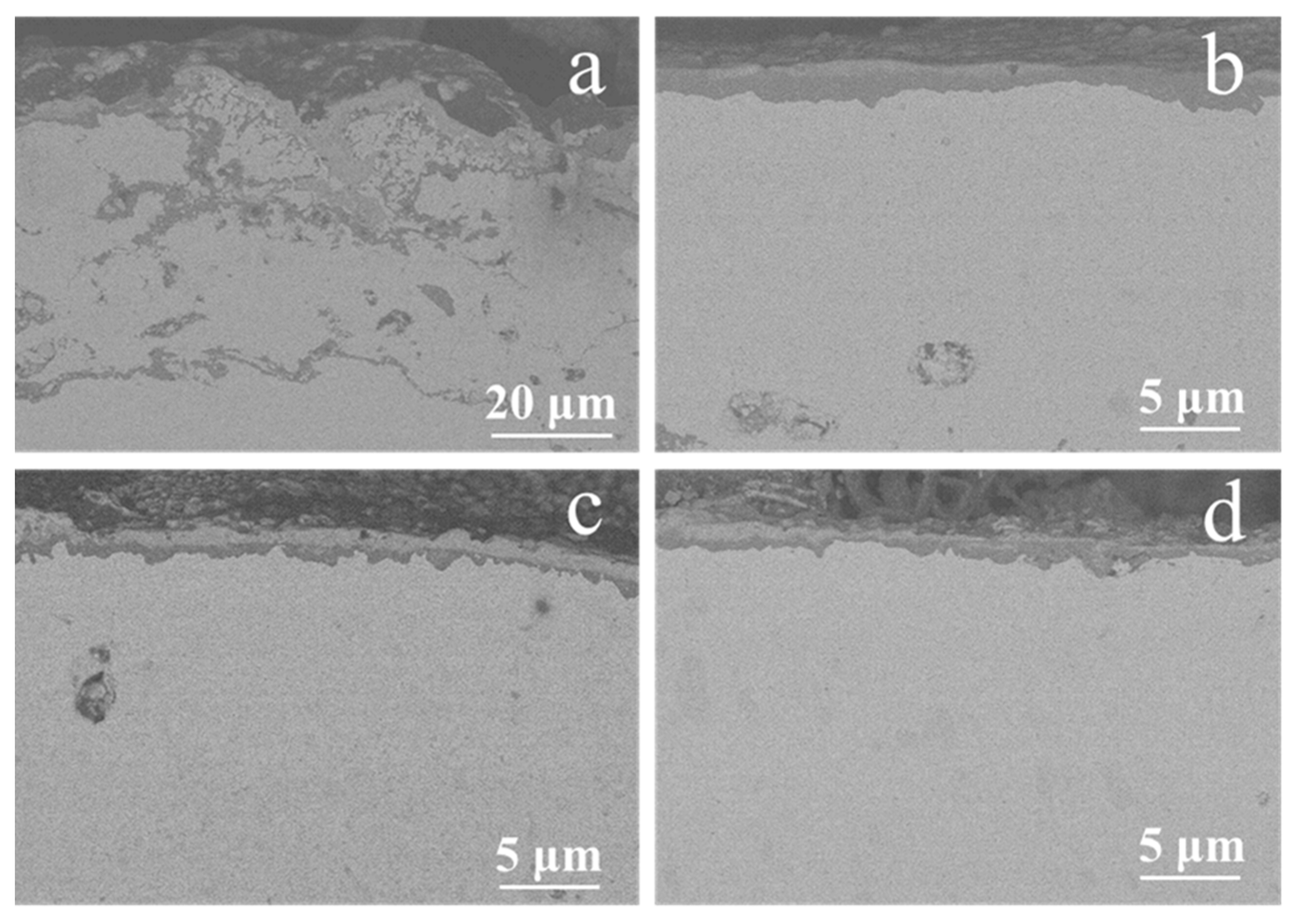
The sectional SEM backscattering images of the NiCrAlY coating before and after a high-current pulsed electron beam irradiation which was static oxidized at 900 °C for 200 h are shown in Figure 6. The TGO layer on the surface of the original NiCrAlY coating after static oxidation was thick, uneven and discontinuous, and serious oxidation also occurred inside the coating (Figure 6a). However, under the irradiation of a high-current pulsed electron beam (Figure 6b–d), a micrometer scale dense Al oxide layer formed on the NiCrAlY coating surface after static oxidation, and the TGO layer was thin, uniform and continuous. Under the oxide layer, there was a poor Al layer with the thickness of more than 10 μm. The dense oxide layer is beneficial to improve the oxidation resistance of the NiCrAlY coating.

Figure 6.
Sectional SEM backscattering images of the NiCrAlY coating before and after a high-current pulsed electron beam irradiation with static oxidation at 900 °C for 200 h: (a) nonirradiated, (b) 12 J/cm2, (c) 15 J/cm2, (d) 18 J/cm2.
Figure 7 shows the XRD pattern of the NiCrAlY coating before and after electron beam irradiation at an energy density of 18 J/cm2 with static oxidation for 200 h. After 200 h of static oxidation, the XRD diffraction peak of the original coating showed that the oxidation products included mainly α-Al2O3, NiCr2O4 and NiO, while the oxides of the irradiated NiCrAlY bond coat were mainly composed of α-Al2O3 and contained little NiO but no NiCr2O4. The oxidation products obtained by XRD analysis were consistent with the results of the EDS analysis. A similar phenomenon was found in the reference [16], where most of the oxidation products of the bond coat were inhibited after a high-current pulsed electron beam irradiation. As can be deduced from Figure 6, the dense α-Al2O3 layer formed on the surface of the NiCrAlY coating after electron beam irradiation can effectively prevent the diffusion of oxygen elements to the matrix and impede further oxidation of the coating at a high temperature, thus improve its oxidation resistance. The oxides of the original NiCrAlY coating mainly contain Al oxides, as well as Cr and Ni oxides, which had adverse effects on the oxidation resistance of the coating. In the thermal barrier coating system, the improvement of the oxidation resistance of the adhesive layer can make the generated TGO relatively smooth and compact, thanks to which the coating becomes difficult to fall off; thus, it significantly improves the service life of the thermal barrier coating [17,28].
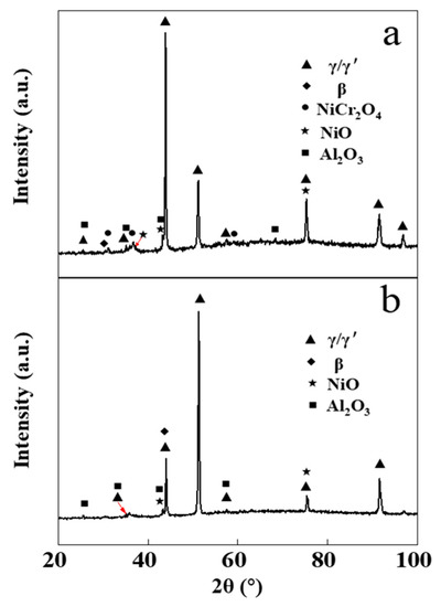
Figure 7.
XRD patterns of the NiCrAlY bond coat before and after a high-current pulsed electron beam irradiation with static oxidation at 900 °C for 200 h: (a) nonirradiated, (b) 18 J/cm2.
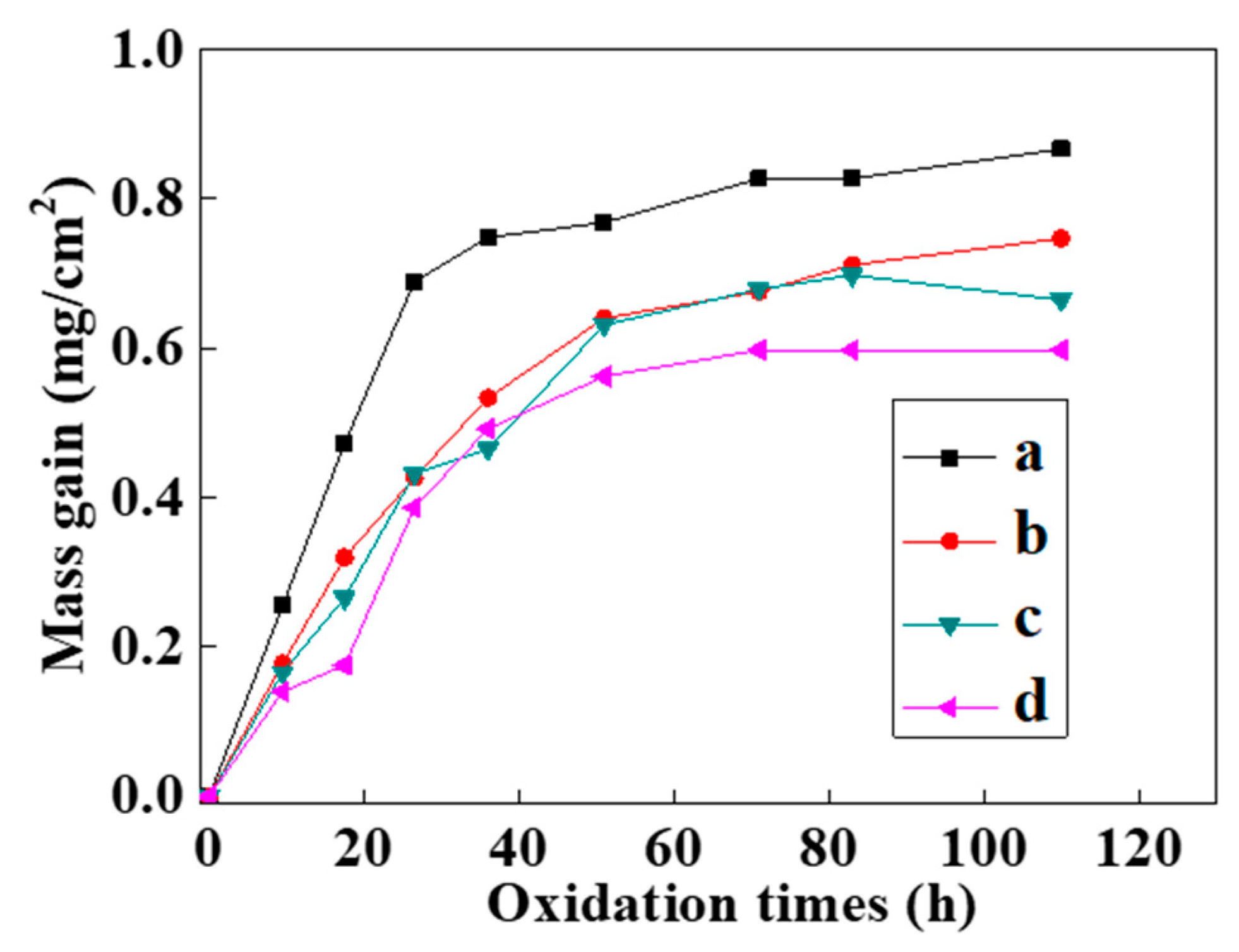
Figure 8 shows the static oxidation kinetics curves of the NiCrAlY coating at 900 °C. The oxidation kinetics curves of the bond coat before and after the intense current electron beam irradiation approximately conformed to a parabola (Figure 8). In the initial stage of the oxidation weight gain (ΔW), the oxidation rate was relatively fast. In the first 10 h of oxidation, ΔW of all the coatings was noticeable. And the oxidation weight gain of the original NiCrAlY coating was slightly faster than that of the coating irradiated by the pulsed electron beam. As the oxidation time increased continually to 30 h, the oxidation weight gain of the original coating was more obvious than that of the electron beam irradiated coating, while this oxidation weight gain increased slowly from 30 to 110 h. However, the coating irradiated by electron beams did not gain significant weight after oxidation for 50 h.
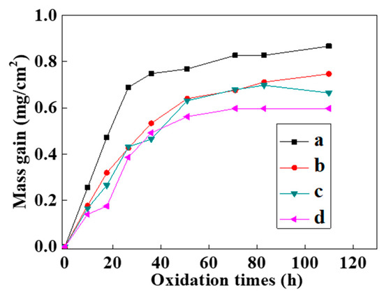
Figure 8.
Static oxidation kinetics curves of the NiCrAlY bond coat at 900 °C before and after a high-current pulsed electron beam irradiation: (a) nonirradiated, (b) 12 J/cm2, (c) 15 J/cm2, (d) 18 J/cm2.
The oxidation kinetics curve was analyzed according to the following equation [29]:
In the formula, n is the rate index, k is the reaction speed constant, t is the oxidation time and c is the constant. A linear equation can be obtained by taking the logarithm for both sides of Equation (6):
and were substituted into the oxidation kinetics data obtained in the experiment to draw a diagram, the rate exponent n could be obtained by linear fitting. The n values of the oxidation kinetics curves of the NiCrAlY coating before and after high-current pulsed electron beam irradiation with the energy densities of 12 J/cm2, 15 J/cm2 and 18 J/cm2 were 2.21, 1.74, 1.67 and 1.53. The oxidation rate index of the coating after electron beam treatment was significantly lower than that of the untreated coating, but there was no obvious dependence on the electron beam parameters. The changes of the oxidation rate index of the coating after different electron beam treatment were within the error range. From the static oxidation experiment, we concluded that the oxidation resistance of the coating was significantly improved after the electron beam treatment.
4. Conclusions
The NiCrAlY bond coat prepared by low-pressure plasma spraying has a lamellar structure, loose and porous. This loose porous structure is conducive to the entry of O and other elements, thus forming an over-thick TGO layer, which is not conducive to improve the oxidation resistance of the coating. The interaction between the high-current pulsed electron beam and the solid is a process of rapid heating and solidification. The strong thermal effect can make the temperature reach the melting point, even the boiling point, of the NiCrAlY bond coat. This flattens the surface of the NiCrAlY bond coat, the loose porous structure disappears, and the remelting layer with the thickness of several μm is formed on the surface of the NiCrAlY bond coat. After the electron beam irradiation, a dense, uniformly distributed TGO layer of a micrometer scale is formed on the NiCrAlY bond coat under the static oxidized; the main component is α-Al2O3, which can effectively prevent O and other elements from further diffusion into the coating and significantly improves the oxidation resistance of the NiCrAlY bond coat.
Author Contributions
Conceptualization, X.M. and N.N.K.; methodology, X.M.; software, L.Z.; validation, X.M.; formal analysis, X.M. and X.Z.; investigation, P.Z. and Y.G.; resources, X.M. and N.N.K.; data curation, N.L. and P.Z.; writing—original draft preparation, X.M.; writing—review and editing, X.Z. and L.Z.; visualization, Y.G. and N.L.; supervision, X.M.; project administration, X.M.; funding acquisition, X.M. All authors have read and agreed to the published version of the manuscript.
Funding
This research was funded by the National Natural Science Foundation of China (No. 11975065, No. 11911530086 and No. 11675035).
Institutional Review Board Statement
Not applicable.
Informed Consent Statement
Not applicable.
Data Availability Statement
Data sharing is not applicable to this article.
Conflicts of Interest
The authors declare no conflict of interest.
References
- Bernard, B.; Quet, A.; Bianchi, L.; Joulia, A.; Malié, A.; Schick, V.; Rémy, B. Thermal insulation properties of YSZ coatings: Suspension Plasma Spraying (SPS) versus Electron Beam Physical Vapor Deposition (EB-PVD) and Atmospheric Plasma Spraying (APS). Surf. Coat. Technol. 2017, 318, 122–128. [Google Scholar] [CrossRef]
- Nieto, A.; Walock, M.; Ghoshal, A.; Zhu, D.; Gamble, W.; Barnett, B.; Murugan, M.; Pepi, M.; Rowe, C.; Pegg, R. Layered, composite, and doped thermal barrier coatings exposed to sand laden flows within a gas turbine engine: Microstructural evolution, mechanical properties, and CMAS deposition. Surf. Coat. Technol. 2018, 349, 1107–1116. [Google Scholar] [CrossRef]
- Mori, T.; Kuroda, S.; Murakami, H.; Katanoda, H.; Sakamoto, Y.; Newman, S. Effects of initial oxidation on β phase depletion and oxidation of CoNiCrAlY bond coatings fabricated by warm spray and HVOF processes. Surf. Coat. Technol. 2013, 221, 59–69. [Google Scholar] [CrossRef]
- Mobarra, R.; Jafari, A.H.; Karaminezhaad, M. Hot corrosion behavior of MCrAlY coatings on IN738LC. Surf. Coat. Technol. 2006, 201, 2202–2207. [Google Scholar] [CrossRef]
- Waki, H.; Kitamura, T.; Kobayashi, A. Effect of Thermal Treatment on High-Temperature Mechanical Properties Enhancement in LPPS, HVOF, and APS CoNiCrAlY Coatings. J. Therm. Spray Technol. 2009, 18, 500–509. [Google Scholar] [CrossRef]
- Yang, S.; Yuan, H.; Zeng, W.; Guo, H. Chemo-thermo-mechanical modeling of EB-PVD TBC failure subjected to isothermal and cyclic thermal exposures. Int. J. Fatigue 2020, 141, 105817. [Google Scholar] [CrossRef]
- Silva, S.A.; Oliveira, A.C.C.; Pita, G.R.; Ferreira, M.F.S.; de Vasconcelos, G. Study of Wear on Nicraly Coating Sprayed by HVOF on 316 Steel and Laser CO2 Remelting Process. Mater. Sci. Forum 2018, 930, 322–326. [Google Scholar] [CrossRef]
- Naumenko, D.; Pillai, R.; Chyrkin, A.; Quadakkers, W.J. Overview on Recent Developments of Bondcoats for Plasma-Sprayed Thermal Barrier Coatings. J. Therm. Spray Technol. 2017, 26, 1743–1757. [Google Scholar] [CrossRef]
- Reddy, M.; Prasad, C.D.; Patil, P.; Ramesh, M.R.; Rao, N. Hot corrosion behavior of plasma-sprayed NiCrAlY/TiO2 and NiCrAlY/Cr2O3/YSZ cermets coatings on alloy steel. Surf. Interfaces 2021, 22, 100810. [Google Scholar] [CrossRef]
- Mahade, S.; Venkat, A.; Curry, N.; Leitner, M.; Joshi, S. Erosion Performance of Atmospheric Plasma Sprayed Thermal Barrier Coatings with Diverse Porosity Levels. Coatings 2021, 11, 86. [Google Scholar] [CrossRef]
- Lu, Z.; Myoung, S.-W.; Jung, Y.-G.; Balakrishnan, G.; Lee, J.; Paik, U. Thermal fatigue behavior of air-plasma sprayed thermal barrier coating with bond coat species in cyclic thermal exposure. Materials 2013, 6, 3387–3403. [Google Scholar] [CrossRef] [PubMed]
- Shulov, V.A.; Engel’ko, V.I.; Gromov, A.N.; Teryaev, D.A.; Bytsenko, O.A.; Shirvan’yants, G.G. Application of high-current pulsed electron beams for the restoration of operational properties of the blades of gas-turbine engines. Russ. J. Non-Ferr. Met. 2015, 56, 333–338. [Google Scholar] [CrossRef]
- Weisenburger, A.; Rizzi, G.; Scrivani, A.; Mueller, G.; Nicholls, J.R. Pulsed electron beam treatment of MCrAlY bondcoats for EB-PVD TBC systems part 1 of 2: Coating production. Surf. Coat. Technol. 2007, 202, 704–708. [Google Scholar] [CrossRef]
- Cai, J.; Lv, P.; Guan, Q.; Xu, X.; Lu, J.; Wang, Z.; Han, Z. Thermal Cycling Behavior of Thermal Barrier Coatings with MCrAlY Bond Coat Irradiated by High-Current Pulsed Electron Beam. ACS Appl. Mater. Interfaces 2016, 8, 32541–32556. [Google Scholar] [CrossRef]
- Cai, J.; Li, G.; Li, C.; Zhang, C.; Lv, P.; Guan, Q. Transient oxidation behavior of MCrAlY coating irradiated by high-current pulsed electron beam. Mater. Res. Express 2018, 5, 126515. [Google Scholar] [CrossRef]
- Cai, J.; Li, C.; Yao, Y.; Lyu, P.; Guan, Q.; Li, Y.; Lu, J. Microstructural modifications and high-temperature oxidation resistance of arc ion plated NiCoCrAlYSiHf coating via high-current pulsed electron beam. Corros. Sci. 2021, 182, 109281. [Google Scholar] [CrossRef]
- Ivanov, Y.F.; Gromov, V.E.; Zaguliaev, D.V.; Konovalov, S.V.; Rubannikova, Y.A.; Semin, A.P. Prospects for the Application of Surface Treatment of Alloys by Electron Beams in State-of-the-Art Technologies. Usp. Fiz. Met. 2020, 21, 345–362. [Google Scholar] [CrossRef]
- Shulov, V.A.; Gromov, A.N.; Teryaev, D.A.; Engel’ko, V.I. Application of high-current pulsed electron beams for modifying the surface of gas-turbine engine blades. Russ. J. Non-Ferr. Met. 2016, 57, 256–265. [Google Scholar] [CrossRef]
- Meisner, L.L.; Markov, A.B.; Proskurovsky, D.I.; Rotshtein, V.P.; Ozur, G.E.; Meisner, S.N.; Yakovlev, E.V.; Poletika, T.M.; Girsova, S.L.; Semin, V.O. Effect of inclusions on cratering behavior in TiNi shape memory alloys irradiated with a low-energy, high-current electron beam. Surf. Coat. Technol. 2016, 302, 495–506. [Google Scholar] [CrossRef]
- Lv, P.; Sun, X.; Cai, J.; Zhang, C.; Liu, X.; Guan, Q. Microstructure and high temperature oxidation resistance of nickel based alloy GH4169 irradiated by high current pulsed electron beam. Surf. Coat. Technol. 2017, 309, 401–409. [Google Scholar] [CrossRef]
- Rotshtein, V.P.; Ivanov, Y.F.; Markov, A.B.; Proskurovsky, D.I.; Karlik, K.V.; Oskomov, K.V.; Uglov, B.V.; Kuleshov, A.K.; Novitskaya, M.V.; Dub, S.N.; et al. Surface alloying of stainless steel 316 with copper using pulsed electron-beam melting of film–substrate system. Surf. Coat. Technol. 2006, 200, 6378–6383. [Google Scholar] [CrossRef]
- Qu, W.; Qin, Y.; Zhang, P.; Mei, X.; Hao, S.; Zhao, J.; Dong, C. Simulation of temperature field and melting depth of an Y2O3-stabilized ZrO2 thermal barrier coating sealed by high-current pulsed electron beam. Surf. Coat. Technol. 2011, 205, 4956–4959. [Google Scholar] [CrossRef]
- Raj, S.V. Thermophysical Properties of Cold- and Vacuum Plasma-Sprayed Cu-Cr-X Alloys, NiAl and NiCrAlY Coatings II: Specific Heat Capacity. J. Mater. Eng. Perform. 2017, 26, 5472–5480. [Google Scholar] [CrossRef]
- Kobylanska-Szkaradek, K. Structure and property changes of air-sprayed NiCrAlY overlay coatings after laser remelting. In Proceedings of the Laser Technology VI: Applications, Szczecin, Poland, 27 September–1 October 1999; Volume 4238, p. 131. [Google Scholar]
- Gil, A.; Shemet, V.; Vassen, R.; Subanovic, M.; Toscano, J.; Naumenko, D.; Singheiser, L.; Quadakkers, W.J. Effect of surface condition on the oxidation behaviour of MCrAlY coatings. Surf. Coat. Technol. 2006, 201, 3824–3828. [Google Scholar] [CrossRef]
- Padture, N.P.; Gell, M.; Jordan, E.H. Thermal Barrier Coatings for Gas-Turbine Engine Applications. Science 2002, 296, 280–284. [Google Scholar] [CrossRef] [PubMed]
- Mei, X.; Liu, X.; Wang, C.; Wang, Y.; Dong, C. Improving oxidation resistance and thermal insulation of thermal barrier coatings by intense pulsed electron beam irradiation. Appl. Surf. Sci. 2012, 263, 810–815. [Google Scholar] [CrossRef]
- Cai, J.; Guan, Q.; Yang, S.; Yang, S.; Wang, Z.; Han, Z. Microstructural characterization of modified YSZ thermal barrier coatings by high-current pulsed electron beam. Surf. Coat. Technol. 2014, 254, 187–194. [Google Scholar] [CrossRef]
- Ye, X.; Wang, L.; Tse, Z.T.H.; Tang, G.; Song, G. RETRACTED: Effects of high-energy electro-pulsing treatment on microstructure, mechanical properties and corrosion behavior of Ti–6Al–4V alloy. Mater. Sci. Eng. C 2015, 49, 851–860. [Google Scholar] [CrossRef]


Publisher’s Note: MDPI stays neutral with regard to jurisdictional claims in published maps and institutional affiliations. |
© 2021 by the authors. Licensee MDPI, Basel, Switzerland. This article is an open access article distributed under the terms and conditions of the Creative Commons Attribution (CC BY) license (https://creativecommons.org/licenses/by/4.0/).