Article

Effect of Substrate Biasing on the Epitaxial Growth and Structural Properties of RF Magnetron Sputtered Germanium Buffer Layer on Silicon

Department of Optics and Photonics, National Central University, 300 Chung-da Road, Chung-Li, Taoyuan 32001, Taiwan
*
Author to whom correspondence should be addressed.
Coatings 2021, 11(9), 1060; https://doi.org/10.3390/coatings11091060
Submission received: 6 August 2021 / Revised: 28 August 2021 / Accepted: 30 August 2021 / Published: 2 September 2021
(This article belongs to the Special Issue Plasma Surface Engineering II)

Abstract

:
High-quality single-crystal-like Ge (004) thin films have been epitaxially grown using radio-frequency magnetron sputtering on Si (001) substrates successfully. The crystalline quality of the Ge films can be obviously improved by applying a positive bias on the substrate holder. X-ray diffraction measurements show that the single-crystal-like Ge film has a narrow full width at half maximum of 0.26°. The perpendicular lattice constant ( a Ge ) and in-plane lattice constant ( a Ge ) are 0.5671 and 0.564 nm. The Raman shift full width at half maximum shows that the defects in the film are obviously reduced. Transmission electron microscopy diffraction patterns also show that the Ge (004) film has good crystalline quality. The results can be applied as Ge buffer layers on Si substrates for the fabrication of high-efficiency III–V solar cells and photodetectors.

1. Introduction

The high near-infrared absorption property of Ge material has been widely used in III–V multijunction solar cells and photodetectors [1,2,3,4]. However, it is expensive to fabricate III–V solar cells on 100-µm-thick Ge substrates. Only a few microns of Ge are needed to effectively absorb sunlight [5]. According to data from the National Renewable Energy Laboratory, the cost of 6-inch Ge wafers is as high as $150 each [6]. Epitaxy Ge films grown on low-cost Si substrates have become a good alternative to Ge substrates. However, there is a 4.2% lattice mismatch between Ge and Si. Many researchers reported different process methods to improve the lattice mismatch between Ge and Si. Table 1 shows the related process methods and experimental results. Chemical vapor deposition (CVD) is the most popular method [7]. The Ge film on Si substrate produced by reduced pressure chemical vapor deposition (RPCVD) has the smallest full width at half maximum (FWHM) value of X-ray diffractometer (XRD) and root mean square (RMS) value of the atomic force microscope (AFM), which is currently the best Ge film epitaxial method [8,9]. Electron cyclotron resonance chemical vapor deposition (ECR-CVD) process temperature is the lowest, and its FWHM of XRD, at a very thin epitaxial thickness, has a lower value [10]. However, the explosive GeH4 gas is injected as a reaction gas in the CVD system to fabricate Ge films. In addition, GeH4 gas is more expensive than bulk Ge. Compared with the CVD system, the physical vapor deposition (PVD) system is more stable, cheaper, and safer. PVD process is not an easy method to fabricate epitaxial Ge films. The FWHM of XRD is about 1100 arcsec [11,12,13], which is larger than the CVD process. Additionally, the annealing process has been used to increase the crystalline quality of Ge films. However, high temperature annealing will cause Ge atoms and Si atoms to diffuse into each other [14], which will change the material properties and doping concentration of the Ge film. Therefore, the epitaxial growth of a high-quality single-crystal-like Ge film on a Si substrate without an annealing process is important. Growth using sputtering systems, with the advantages of high compatibility with the Si process, high safety, high uniformity, and low cost, has become an interesting solution.
In this study, a radio-frequency (RF) magnetron sputtering method has been applied for the growth of single-crystal-like Ge films on Si substrates. The crystallization quality of the Ge film is improved by controlling the sputtering power, the positive bias voltage on the substrate, and the hydrogen flow rate. The application of a positive bias to the substrate can greatly change the plasma distribution in the chamber and reduce the occurrence of ion bombardment, significantly improving the crystalline quality of the film. A low-cost Ge buffer layer on Si substrates can be used as an epitaxial substrate for heterogeneous materials in III–V multijunction solar cells and photodetectors.

2. Experiments

The substrates for this study were n-type phosphorus doping CZ Si (001) wafers with resistivity of 1–10 ohm-cm, thickness of 500 um, and cutting angle of 0° (I-MEI Materials Inc., New Taipei, Taiwan). The Ge sputtering target had a diameter of 3 inches with a purity of 99.999% (Summit-Tech Resource Inc., Hsinchu, Taiwan). The Si substrates were cleaned by the standard RCA process [15] and immersed in 2% HF to remove the surface oxide layer before epitaxial growth. Then, the Si substrates were deposited with Ge using RF magnetron sputtering (Sputtering system, YUJAY Technology Inc., Hsinchu, Taiwan) to epitaxially grow the Ge films. The argon flow was 10 sccm, the working pressure was 1.2 × 10⁻³ Torr, the distance from target to substrate was 8 cm, the process temperature was 600 °C, and the film thickness was controlled to be about 450 nm. To evaluate the best epitaxial growth conditions of the Ge films, the sputtering power, positive bias voltage on substrate, and hydrogen flow rate were adjusted to 75, 100 and 125 W; 0, +50 and +100 V; and 0, 0.8 and 1.5 sccm, respectively.
In regard to the film analysis, the two-theta mode of XRD (D8 Advance, Bruker Inc., Billerica, USA) was used to analyze the crystalline orientation, FWHM, and the strain of the films. The scanning speed and resolution of XRD are 0.1 s and 0.01°, respectively. The Raman spectrometer (BWII RAMaker, Protrustech Inc., Tainan, Taiwan) uses a laser light source with a wavelength of 532 nm to analyze crystallographic defects. The integration time and superposition times of Raman spectrometer are 1 s and 10 times, respectively. AFM (VEECO Innova SPM, Veeco Instruments Inc., New York, NY, USA) was used to measure the surface roughness of the films. The sample is cut into thin slices less than 100 nm using a focused ion beam (FIB) and placed on a copper mesh as a transmission electron microscopy (TEM, JEM2100, JEOL Ltd., Tokyo, Japan) measurement sample. TEM was used to observe the arrangement of Ge atoms and the degree of dislocation defects.

3. Results and Analysis

During the process, high-energy argon ions bombard the Ge target for deposition, and the substrate is at a low voltage compared to the argon ions in the chamber. Therefore, the high-energy argon ions bombard the samples with ions, making it difficult for Ge atoms to bond with the substrate [16], as shown in Figure 1. Even after a film is formed, the Ge–Ge molecular bonds of the Ge film can be broken by the ion bombardment, degrading the crystalline quality. Therefore, adding a positive bias to the substrate can reduce the ion bombardment and retain more Ge crystalline. The positive bias can also attract electrons to hit the film and achieve electron beam annealing.
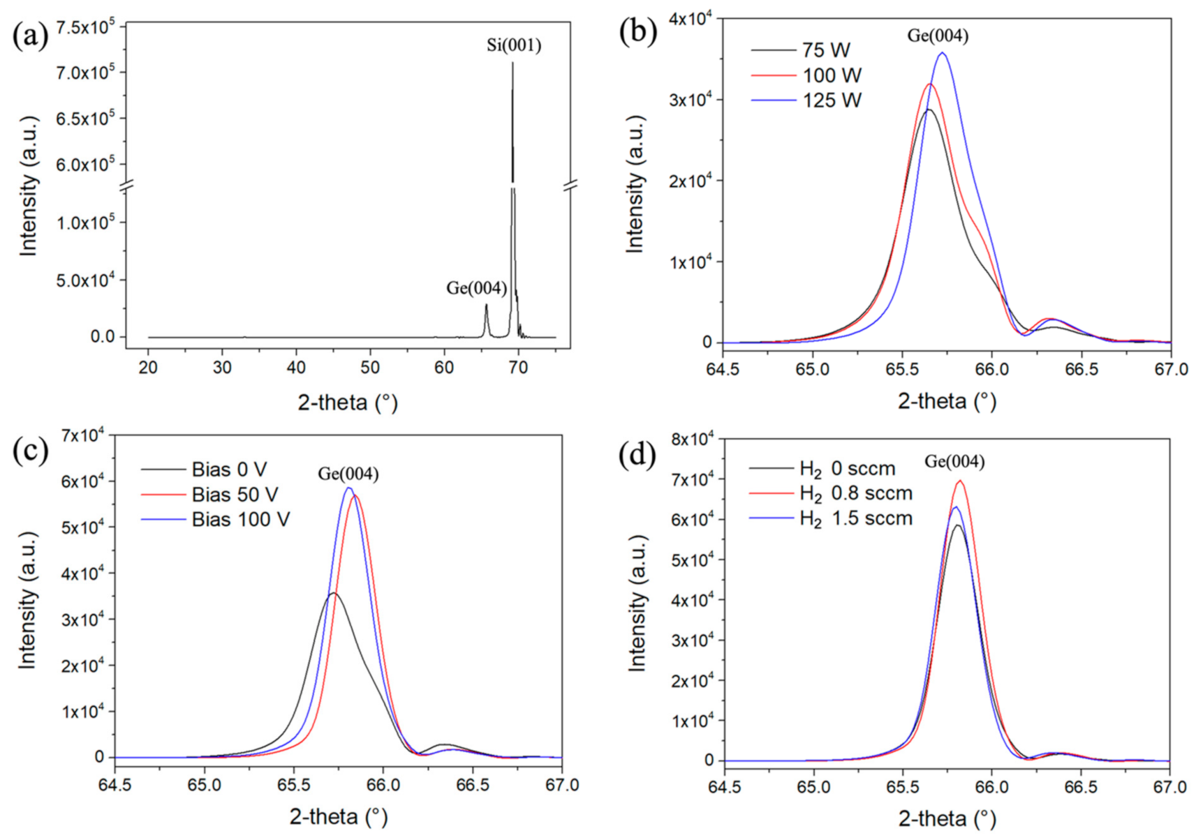
The sputtering power during RF magnetron sputtering was then adjusted to 75, 100 and 125 W. Figure 2a shows an X-ray diffraction (XRD) measurement of the 75 W sputtering power Ge film with a wide scanning range, with 2θ from 20° to 80°. There are only two XRD peaks in this measurement, which belong to the (004) planes of the Ge film (65° to 66°) and Si substrate (69.1°) [17]. From this result, it is determined that the Ge thin film is a single crystalline. As shown in Figure 2b, the results of samples from all the sputtering power parameters range in XRD diffraction angle between 64.5° to 67°. The XRD diffraction peak for the 75, 100 and 125 W sputtering power samples at 65.64°, 65.66° and 65.72°, respectively. As the sputtering power is increased, the Ge atoms of the target material obtain energy from the bombarding argon ions. When the Ge atoms are deposited on the substrate, the energy obtained will be provided to the Ge atoms for epitaxy. In addition, the XRD diffraction angle is close to 66°, which is the (004) Ge value [18]. The FWHM of the XRD peak are 0.41°, 0.42° and 0.37°, respectively. The FWHMs of the 75 and 100 W sputtering power are similar, which shows the similar crystalline quality, and the 125 W sputtering power film has the smallest FWHM, which shows that the crystalline quality increases with higher sputtering power. Next, the sputtering power was fixed at 125 W, and the bias voltage of the substrate was changed to 0, 50 and 100 V to explore the role of the bias voltage on the crystalline quality of the film. The XRD diffraction angle shown in Figure 2c. The XRD diffraction peak for the 0, 50 and 100 V substrate bias samples at 65.72°, 65.84° and 65.8°, respectively. This is closer to the bulk single-crystal-like Ge (004). The FWHM is shown to decrease with increasing bias voltage, with values of 0.37°, 0.27° and 0.28°, respectively. This indicates that the 50 and 100 V positive biases can improve Ge (004) crystalline quality. In addition, 100 V positive bias can achieve higher XRD peak shows the better crystalline quality. Hydrogen can reduce the generation of dangling bonds on the substrate surface and the Ge film [19,20]. According to the hydrogen atom etching model, a low concentration of hydrogen can dissociate weaker ionic bonds and synthesize Si–Ge and Ge–Ge bonds. The chemical annealing model shows that hydrogen atoms can enter the film and synthesize with dangling bonds to improve the crystalline quality of the film even when the Ge film is formed [21]. When the bias voltage of the substrate is 100 V, the crystalline quality of the film can be further explored by changing the hydrogen flow from 0 to 0.8 or 1.5 sccm. The XRD measurement results in Figure 2d show higher diffraction intensity with the production of more Ge (004) crystals. The XRD diffraction peak for the 0, 0.8 and 1.5 sccm hydrogen flow samples at 65.8°, 65.82° and 65.8°, respectively. Therefore, hydrogen contributes to the crystallization of Ge, but does not make much difference to the adjustment of the lattice size. After adding hydrogen, the FWHM slightly decreases to 0.28°, 0.26° and 0.27°, respectively.
The lattice constant in the perpendicular direction ( a G e ) based on Bragg’s Law can be calculated from the XRD peak angle of Ge (004) as follows:
a G e = 2 λ sin θ G e
where λ = 0.15406 nm is the emitted K α 1 X-ray in XRD. The lattice constant in the in-plane direction ( a G e ) of the Ge film can be calculated by using the bulk lattice constant ( a G e ) and the lattice constant in the perpendicular direction ( a G e ) of the Ge film:
a G e = 1 + υ a G e 1 υ a G e 2 υ
where a G e = 0.56578 nm, and Poisson’s ratio υ = 0.271. The compressive or tensile strain R of the Ge film can be calculated by the following equation [22]:
R = a G e a S i a G e a S i
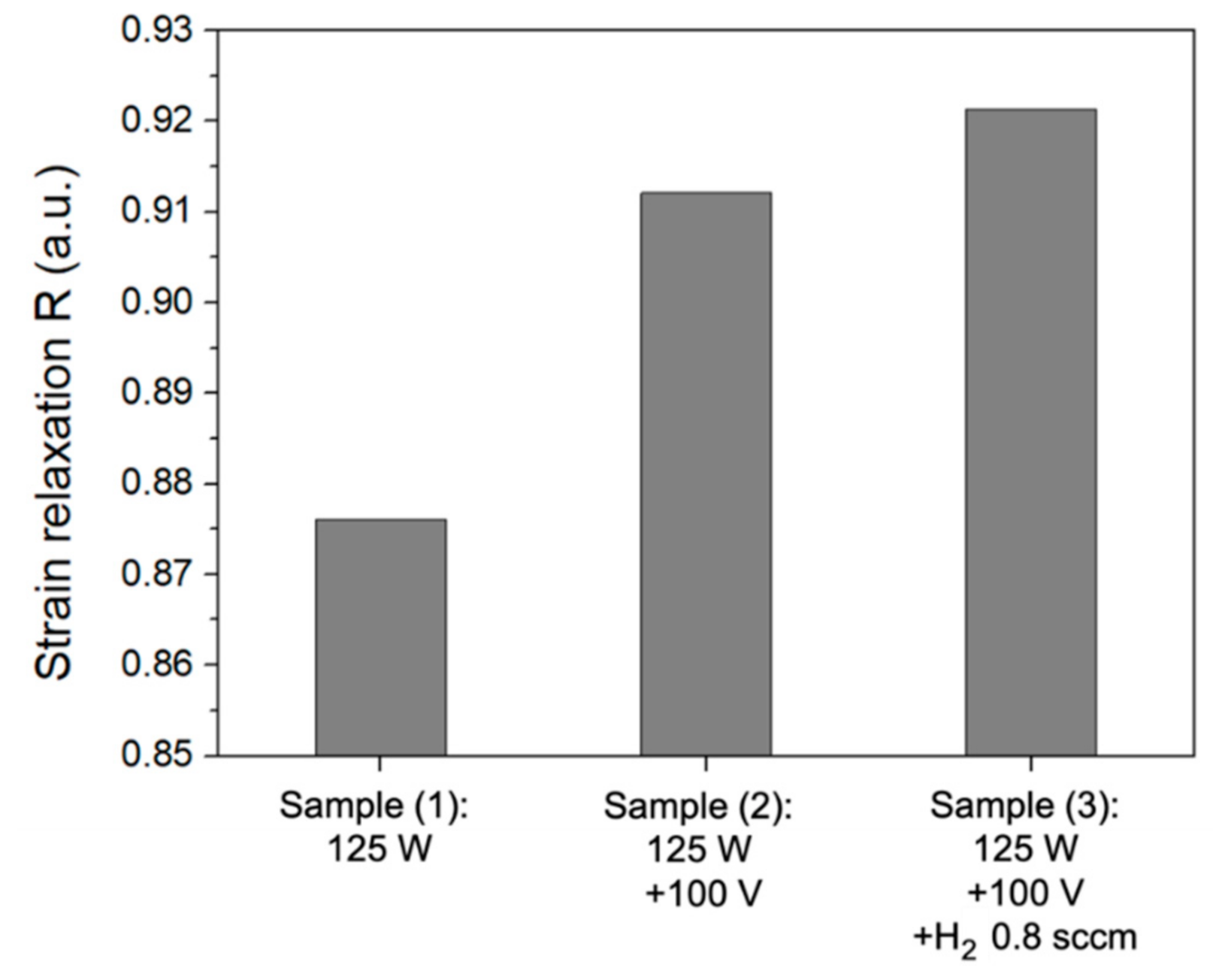
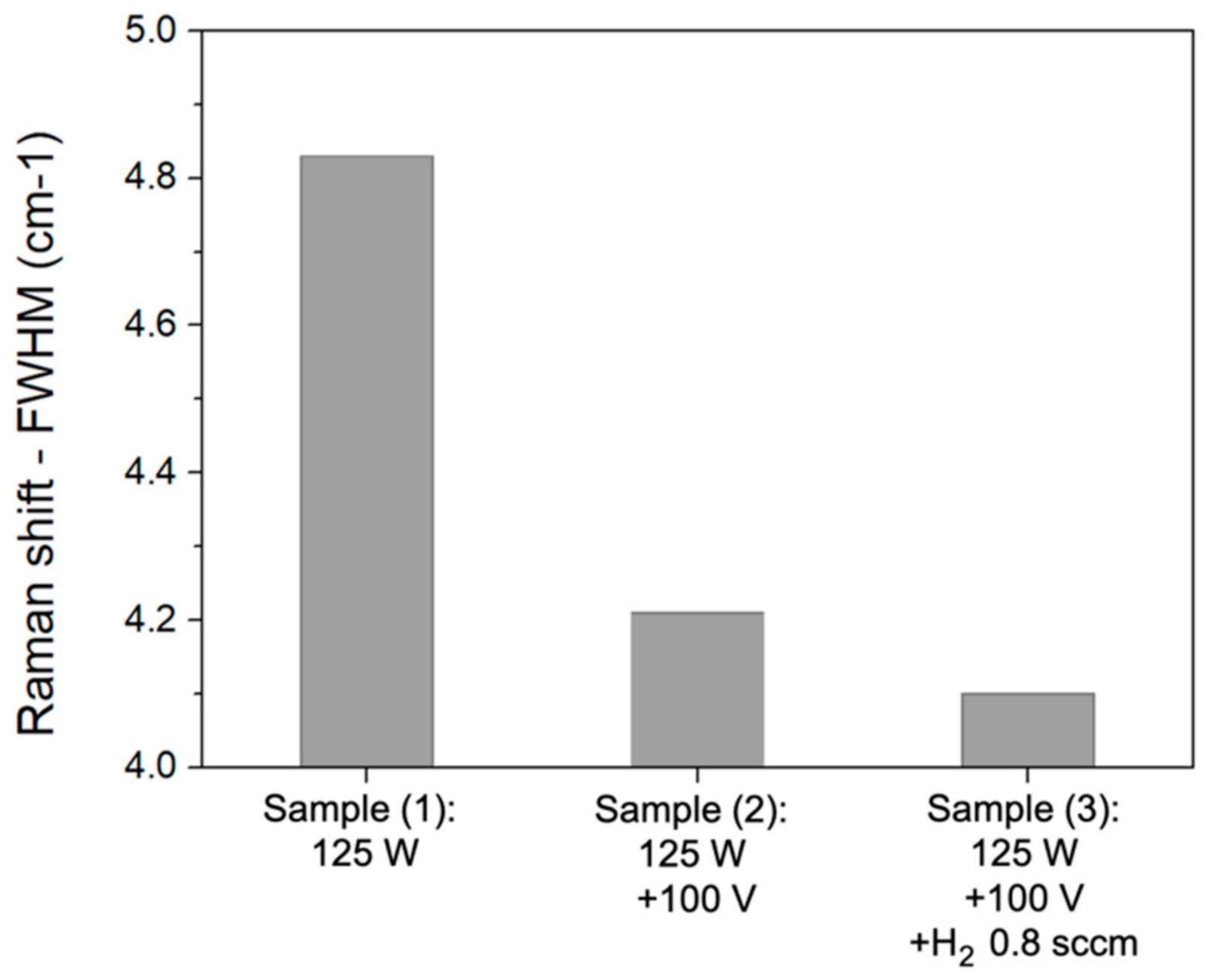
where the Si lattice constant is a S i = 0.5431 nm. When the strain relaxation R = 1, there is no stress in the Ge film; when R < 1, there is compressive stress; and when R > 1, there is tensile stress. The strain relaxation R of the three samples has been calculated and defined as sample (1): the sputtering power of 125 W, sample (2): the sputtering power of 125 W and the substrate bias of 100 V, and sample (3): the sputtering power of 125 W, the substrate bias of 100 V, and the hydrogen flow of 0.8 sccm. The results are shown in Figure 3. When the substrate bias and the hydrogen flow of the process conditions were applied, the compressive strains were obviously released. Sample (1) shows that without applying the substrate bias, the Ge film was bombarded by argon plasma and the density of Ge atoms in the film was increased to form a compressive strain. On the contrary, when sample (2) was applied to the substrate bias, the bombardment on the substrate was reduced, and the compressive strain was obviously reduced. Finally, sample (3) is the result with the less compressive strain. Its perpendicular lattice constant ( a G e ) and in-plane lattice constant ( a G e ) are 0.5671 and 0.564 nm, respectively, which are very close to the lattice constant of Ge bulk material [23]. The Raman spectroscopy measurements of these three samples were also analyzed and the Raman shift FWHMs are calculated as shown in Figure 4. The corresponding FWHMs are 4.83, 4.21 and 4.10 cm−1 for samples (1), (2) and (3), respectively. Since the Raman shift is related to the crystallographic defects inside the film, the more defects the larger the FWHM. Sample (3) was fabricated with the optimized process conditions. Its FWHM was significantly reduced and its defects was also decreased.
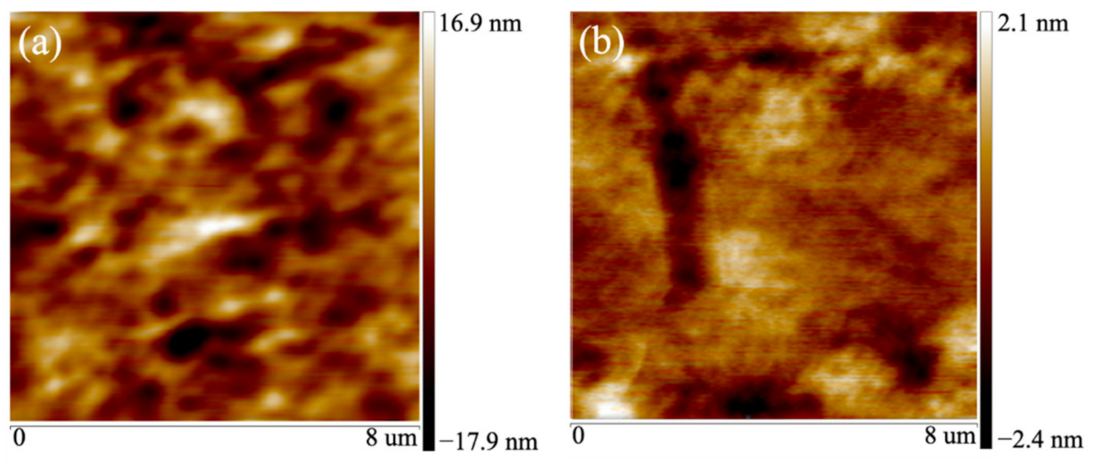
The center and edge surface roughness data of the samples (1), (2) and (3) have been measured by AFM as shown in Table 2. Figure 5 shows the center surface morphology of the samples. When the deposition process was without sample bias, the surface roughness is large, especially on the center. When the sample bias was applied, the surface roughness was effectively reduced. That can be explained by the less argon-ion bombardment. Furthermore, the hydrogen process has been discovered to improve the crystalline quality by etching the parts of the films with more dislocation defects and to slightly increase surface roughness. Fortunately, the overall surface roughness can be maintained at 0.81 nm.
The sample with process parameters of the sputtering power of 125 W, 100 V substrate bias, and hydrogen flow of 0.8 sccm was measured by TEM, as shown in Figure 6. Figure 6a is TEM bright-field measurement, the thickness of the Ge film is 450 nm. Figure 6b is TEM dark-field measurement. This measurement suitable for the analysis of dislocations in the film [24]. The white part in the TEM image of the Ge film is a dislocation [25]. Because of the 4.2% lattice mismatch between the Si substrate and the Ge film, the epitaxial Ge film generated more dislocations at the substrate–film interface. However, as the thickness of the film increased, the lattice mismatch improved, the dislocation density decreased [26], and improved crystalline quality Ge (004) was formed. Figure 6c shows the junction of the Si substrate and the Ge film. The lattice mismatch can be observed in the figure. However, since some Ge atoms have successfully bonded on the Si substrate to form a Ge seed layer, the Ge atoms are epitaxially grown from above and around the seed layer. Figure 6d shows a TEM electron diffraction diagram of the Ge film. The periodic diffraction points confirm that the formed Ge film was a single crystalline. These results confirmed that single-crystal-like Ge film has been successfully grown epitaxially on the Si substrate [27].

4. Conclusions

In this study, a positive bias applied on the substrate during the RF-sputtering process was shown to obviously improve the crystalline quality of the Ge film. When the process parameters are a sputtering power of 125 W, substrate bias of 100 V, and hydrogen flow of 0.8 sccm, the best crystalline quality is obtained for the Ge film. With these process parameters, the XRD results show that the diffraction angle and FWHM are 65.82° and 0.26°, respectively, indicating single-crystal-like Ge. The perpendicular lattice constant ( a Ge ) and in-plane lattice constant ( a Ge ) are 0.5671 and 0.564 nm. The Raman shift FWHM shows that the defects in the film are obviously reduced. TEM diffraction patterns also show that the Ge (004) film has good crystalline quality. These results indicate the successful epitaxial growth of high-quality single-crystalline Ge film on a Si substrate, which can be applied as a Ge buffer layer on Si substrates for the fabrication of high-efficiency III–V solar cells and photodetectors.

Author Contributions

Conceptualization, S.-H.C. and G.-S.Z.; methodology, G.-S.Z.; software, C.-L.L.; validation, C.-L.L.; formal analysis, G.-S.Z.; investigation, C.-L.L.; resources, C.-L.L.; data curation, G.-S.Z.; writing—original draft preparation, G.-S.Z.; writing—review and editing, S.-H.C.; visualization, G.-S.Z.; supervision, S.-H.C.; project administration, S.-H.C.; funding acquisition, S.-H.C. All authors have read and agreed to the published version of the manuscript.

Funding

Ministry of Science and Technology of Taiwan under Grant No. MOST 109-2221-E-008-077-MY3 and MOST 110-2119-M-008-006-MBK.

Institutional Review Board Statement

Not applicable.

Informed Consent Statement

Not applicable.

Conflicts of Interest

The authors declare no conflict of interest.

References

  1. Luque, A. Will we exceed 50% efficiency in photovoltaics? J. Appl. Phys. 2011, 110, 031301. [Google Scholar] [CrossRef]
  2. Yoon, H.; Granata, J.E.; Hebert, P.; King, R.R.; Fetzer, C.M.; Colter, P.C.; Edmondson, K.M.; Law, D.; Kinsey, G.S.; Krut, D.D.; et al. Recent advances in high-efficiency III-V multi-junction solar cells for space applications: Ultra triple junction qualification. Prog. Photovolt Res. Appl. 2005, 13, 133–139. [Google Scholar] [CrossRef]
  3. Cansizoglu, H.; Bartolo-Perez, C.; Gao, Y.; Devine, E.P.; Ghandiparsi, S.; Polat, K.G.; Mamtaz, H.H.; Yamada, T.; Elrefaie, A.F.; Wang, S.Y.; et al. Surface-illuminated photon-trapping high-speed Ge-on-Si photodiodes with improved efficiency up to 1700 nm. Photon. Res. 2018, 6, 734–742. [Google Scholar] [CrossRef]
  4. Suh, D.; Kim, S.; Joo, J.; Kim, G. 36-GHz high-responsivity Ge photodetectors grown by RPCVD. IEEE Photon. Tech. Lett. 2009, 21, 672–674. [Google Scholar]
  5. Colace, L.; Assanto, G. Ge on Si for near-infrared light sensing. IEEE Photonics J. 2009, 1, 69–79. [Google Scholar] [CrossRef]
  6. Horowitz, K.A.W.; Woodhouse, M.; Lee, H.; Smestad, G. A bottom-up cost analysis of a high concentration PV module. AIP Conf. Proc. 2015, 1679, 100001. [Google Scholar]
  7. Littlejohns, C.G.; Khokhar, A.Z.; Thomson, D.J.; Hu, Y.; Basset, L.; Reynolds, S.A.; Mashanovich, G.Z.; Reed, G.T.; Gardes, F.Y. Ge-on-Si plasma-enhanced chemical vapor deposition for low-cost photodetectors. IEEE Photonics J. 2015, 7, 1–8. [Google Scholar] [CrossRef]
  8. Yamamoto, Y.; Zaumseil, P.; Arguirov, T.; Kittler, M.; Tillack, B. Low threading dislocation density Ge deposited on Si (100) using RPCVD. Solid State Electron. 2011, 60, 2–6. [Google Scholar] [CrossRef]
  9. Du, Y.; Kong, Z.; Toprak, M.S.; Wang, G.; Miao, Y.; Xu, B.; Yu, J.; Li, B.; Lin, H.; Han, J.; et al. Investigation of the heteroepitaxial process optimization of Ge layers on Si (001) by Rpcvd. Nanomaterials 2021, 11, 928. [Google Scholar] [CrossRef]
  10. Kuo, W.C.; Lin, C.Y.; Lee, C.C.; Cheng, C.C.; Chang, J.Y. Strain-Controlled of Compressive/Tensile Ge epilayers on Si by electron cyclotron resonance chemical vapor deposition. ECS J. Solid State Sci. Technol. 2016, 5, 529–533. [Google Scholar] [CrossRef]
  11. Sorianello, V.; Colace, L.; Armani, N.; Rossi, F.; Ferrari, C.; Lazzarini, L.; Assanto, G. Low-temperature germanium thin films on silicon. Opt. Mater. Express. 2011, 1, 856–865. [Google Scholar] [CrossRef] [Green Version]
  12. Li, H.S.; Qiu, F.; Xin, Z.H.; Wang, R.F.; Yang, J.; Zhang, J.; Wang, C.; Yang, Y. Investigation of the microstructure and optical properties of Ge films grown by DC magnetron sputtering and in situ annealing. Jpn. J. Appl. Phys. 2016, 55, 061302. [Google Scholar] [CrossRef]
  13. Liu, Z.H.; Hao, X.J.; Huang, J.L.; Li, W.; Ho-Baillie, A.; Green, M.A. Diode laser annealing on Ge/Si (100) epitaxial films grown by magnetron sputtering. Thin Solid Films 2016, 609, 49–52. [Google Scholar] [CrossRef]
  14. Raisknen, J.; Hirvonen, J.; Anitila, A. The diffusion of silicon in germanium. Solid State Electron. 1981, 24, 333–336. [Google Scholar] [CrossRef]
  15. Pan, T.M.; Lei, T.F.; Chao, T.S.; Liaw, M.C.; Ko, F.H.; Lu, C.P. One-step cleaning solution to replace the conventional RCA two-step cleaning recipe for pregate oxide cleaning. J. Electrochem. Soc. 2001, 148, G315–G320. [Google Scholar] [CrossRef]
  16. Miyata, S.; Toyoda, R.; Hashimoto, M.; Iijima, T.; Tonegawa, A.; Matsumura, Y. Effect of sputtering gas ions on thin film properties. J. Japan Inst. Met. Mater. 2016, 80, 280–283. [Google Scholar] [CrossRef] [Green Version]
  17. Oh, J.; Banerjee, S.K.; Campbell, J.C. Metal–Ge–Metal photodetectors on heteroepitaxial Ge-on-Si with amorphous Ge schottky barrier enhancement layers. IEEE Photon. Tech. Lett. 2004, 16, 581–583. [Google Scholar] [CrossRef]
  18. Lee, K.H.; Jandl, A.; Tan, Y.H.; Fitzgerald, E.A.; Tan, C.S. Growth and characterization of Ge epitaxial film on Si (001) with germane precursor in metal organic chemical vapour deposition (MOCVD) chamber. AIP Adv. 2013, 3, 092123. [Google Scholar] [CrossRef]
  19. Yokomichi, H.; Morigaki, K. Evidence for existence of hydrogen-related dangling bonds in hydrogenated amorphous Si. Phil. Mag. Lett. 1996, 73, 283–287. [Google Scholar] [CrossRef]
  20. Beyer, W.; Herion, J.; Wagner, H.; Zastrow, U. Hydrogen stability in amorphous Ge films. Philos. Mag. Part B 1991, 63, 269–279. [Google Scholar] [CrossRef]
  21. Nakamura, K.; Yoshino, K.; Takeoka, S.; Shimizu, I. Roles of atomic hydrogen in chemical annealing. Jpn. J. Appl. Phys. 1995, 34, 442–449. [Google Scholar] [CrossRef]
  22. Liu, Z.; Hao, X.; Ho-Baillie, A.; Tsao, C.Y.; Green, M.A. Cyclic thermal annealing on Ge/Si(100) epitaxial films grown by magnetron sputtering. Thin Solid Films 2015, 574, 99–102. [Google Scholar] [CrossRef]
  23. Miyata, Y.; Ueno, K.; Yoshimura, T.; Ashida, A.; Fujimura, N. Cerium ion doping into self-assembled Ge using three-dimensional dot structure. J. Cryst. Growth 2017, 468, 696–700. [Google Scholar] [CrossRef]
  24. Truong, Q.D.; Devaraju, M.K.; Tomai, T.; Honma, I. Direct Observation of Antisite Defects in LiCoPO4 Cathode Materials by Annular Dark and Bright Field Electron Microscopy. ACS Appl. Mater. Interfaces 2013, 5, 9926–9932. [Google Scholar] [CrossRef]
  25. Toko, K.; Nakazawa, K.; Saitoh, N.; Yoshizawa, N.; Suemasu, T. Improved surface quality of the metal-induced crystallized Ge seed layer and its influence on subsequent epitaxy. Cryst. Growth Des. 2015, 15, 1535–1539. [Google Scholar] [CrossRef]
  26. Dos Santos, D.R.; Torriani, I.L. Crystallite size determination in Mu-C-GE films by X-Ray-Diffraction and raman line-profile analysis. Solid State Comm. 1993, 85, 307–310. [Google Scholar] [CrossRef]
  27. Jain, J.R.; Ly-Gagnon, D.-S.; Balram, K.C.; White, J.S.; Brongersma, M.L.; Miller, D.A.B.; Howe, R.T. Tensile-strained germanium-on-insulator substrate fabrication for silicon-compatible optoelectronics. Opt. Mater. Express. 2011, 1, 1121–1126. [Google Scholar] [CrossRef] [Green Version]
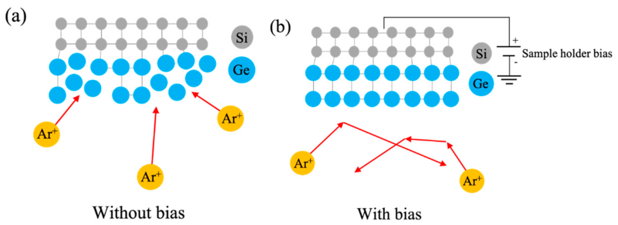
Figure 1. The effect of the bias voltage applied to the Ge films: (a) without bias; (b) with positive bias.
Coatings 11 01060 g001
Figure 2. XRD two-theta mode measurement of RF sputtered Ge thin films on Si substrates with (a) wide 20°–80° scan range; (b) varying sputtering power (75, 100 and 125 W); (c) varying substrate bias voltage (0, 50 and 100 V); and (d) varying hydrogen flow (0, 0.8 and 1.5 sccm).
Coatings 11 01060 g002
Figure 3. The compressive strains of the Ge films.
Coatings 11 01060 g003
Figure 4. The Raman shift FWHM of the Ge films.
Coatings 11 01060 g004
Figure 5. Surface roughness on the sample center: (a) Sample (1):125 W; (b) Sample (3):125 W + 100 V + H2 0.8 sccm.
Coatings 11 01060 g005
Figure 6. TEM: (a) cross-sectional bright-field image; (b) cross-sectional dark-field image; (c) Si substrate and Ge film image; (d) TEM electron diffraction diagram for RF sputtered Ge film grown with a sputtering power of 125 W, substrate bias of 100 V, and hydrogen flow of 0.8 sccm.
Coatings 11 01060 g006
Table 1. Literature Review.
Process EquipmentYearTemp
(°C)
Thickness
(nm)
Annealing Temp
(°C)
XRD/FWHM
(arcsec)
AFM/RMS
(nm)
Ref.
PECVD2015400/25070560010123.5[7]
RPCVD2011550/300470080041.760.44[8]
RPCVD2021650/40014008201310.81[9]
ECR-CVD2016220100-5321.5[10]
Thermal Evaporation2011300200-1188-[11]
DC-Sputtering2016450300750-4.6[12]
RF-Sputtering20164004009101260-[13]
Table 2. The surface roughness of the center and edge of the samples.
Process ParametersSample Center RMS
(nm)
Sample Edge RMS
(nm)
Sample (1): 125 W4.941.04
Sample (2): 125 W + 100 V0.580.42
Sample (3): 125 W+100 V + H2 0.8 sccm0.810.61
Publisher’s Note: MDPI stays neutral with regard to jurisdictional claims in published maps and institutional affiliations.