Article

Coupled Resonance Mechanism of Interface Stratification of Thin Coating Structures Excited by Horizontal Shear Waves

1
School of Mechanical and Materials Engineering, Xi’an University, Xi’an 710065, China
2
Shaanxi Key Laboratory of Surface Engineering and Remanufacturing, Xi’an University, Xi’an 710065, China
3
School of Mechanical Engineering, Xi’an Jiaotong University, Xi’an 710049, China
4
State Key Laboratory for Strength and Vibration of Mechanical Structures, Xi’an Jiaotong University, Xi’an 710049, China
5
Xi’an Key Laboratory of Modern Intelligent Textile Equipment, Xi’an Polytechnic University, Xi’an 710072, China
*
Authors to whom correspondence should be addressed.
Coatings 2022, 12(10), 1509; https://doi.org/10.3390/coatings12101509
Submission received: 21 August 2022 / Revised: 22 September 2022 / Accepted: 2 October 2022 / Published: 9 October 2022
(This article belongs to the Special Issue Application of Coatings in Industry and Means of Transport)

Abstract

:
The coupled resonance mechanism of interface stratification of thin coating structures excited by horizontal shear waves is investigated by the forced vibration solution derived from the global matrix method, the integral transformation method, and the plane wave perturbation method. The interface shear stress reaches the peak at coupling resonance frequencies which are an inherent property of the structure, and decreases with the increase of coating thickness or the increase of shear wave velocity difference between the substrate and coating. At the coupling resonance frequency, the thin coating structure is more easily stratified at the interface. The result could provide a theoretical basis for the popularization and application of ultrasonic deicing/defrosting/de-accretion technology.

1. Introduction

In industry, elastic waves sometimes are performed to disassemble coating structures at the interface [1,2,3]. Therefore, it is with far-reaching significance to investigate the mechanism of interface delamination of accretion structures.
The propagation of elastic waves is one of the main contents in the field of solid mechanics [4,5,6,7]. The particle displacement in the medium is controlled by wave equations which are usually partial differential equations formulated by variational principle, differential principle, higher-order shear deformation principle, and so on [8,9,10,11]. Analytical solutions could be obtained by solving partial differential equations. But it is usually very difficult to solve the partial differential equation, especially the inhomogeneous partial differential equation. Fortunately, some simplified wave equations by mechanical assumptions could be solved by separation of variables methods, the Green’s function method, integral transformation methods, displacement potential function methods, partial wave methods, variational iteration methods, homotopy perturbation methods, and so on [12,13,14,15,16,17,18].
If the displacement and the stress are continuous at interfaces, and the traction is zero on surfaces, the analytical solution of laminated structures with the boundary conditions could be solved by the transfer-matrix method, the stiffness-matrix method, the global-matrix method, and so on [19,20,21,22,23,24]. The free vibration solution and the dispersion equation could be obtained by solving the homogeneous wave equation, while the forced vibration solution could be obtained by solving the inhomogeneous wave equation with external forces [25,26,27]. So far, the displacement solution and the stress solution have received great attention, but the interfacial shear stress solution has received little attention. Due to the lack of analytical solutions to interfacial shear stress, it is impossible to further study the problem.
The study of interface stratification excited by elastic waves begins with the observation of experimental phenomena [28,29]. For example, the ice layer attached to a metal plate is instantly completely stratified by ultrasonic transducers [30,31]. Then, it is proved by the finite element method that the interfacial shear stress directly leads to interfacial delamination [32,33,34,35,36,37,38,39,40,41,42,43,44]. Furthermore, it is found that the interfacial shear stress of double layer structures, sandwich structures, and thin internal layer structures excited by the horizontal shear wave has coupling resonance characteristics [45,46,47]. Coating structures have widely existed in the field of industrial technology [48]. However, the mechanism of interface stratification of thin coating structures excited by elastic waves is still not clear at present.
The solutions of wave equations often contain complex integrals which are solved directly explicitly. But the complex integrals could be solved by the numerical integration method such as the Simpson method, the trapezoidal method, the newton-cotes method, and so on, in which the Gauss–Kronrod quadrature numerical integration method in the Simpson method is particularly valid for integrating oscillating functions [49,50,51,52].
To solve the above problems, the forced vibration solution of the interfacial shear stress of thin coating structures excited by horizontal shear waves is derived. The mechanism of interfacial stratification is studied by analytical methods. The effects of structural inherent properties on interface stratification are analyzed and discussed.

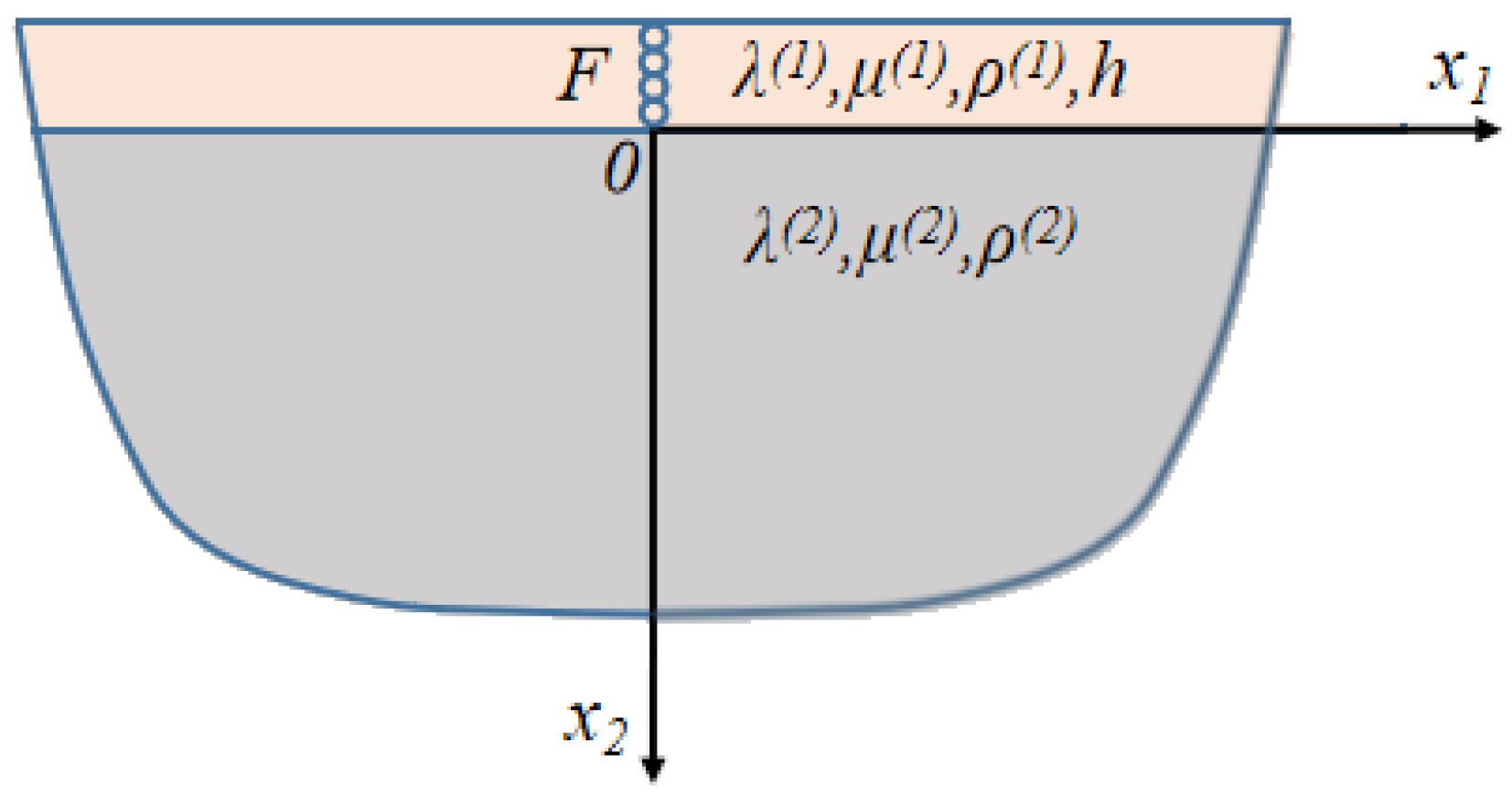
2. The Forced Vibration Solution and the Necessary Condition of Interfacial Stratification of Thin Coating Structures Excited by Horizontal Shear Waves

The forced vibration solution of interfacial stratification of thin coating structures excited by horizontal shear waves is derived from plane wave perturbation methods, integral transformation methods, and global matrix methods. The necessary condition of interfacial stratification is analyzed and discussed by the interfacial shear fatigue failure theory.

2.1. The Forced Vibration Solution of Interface Shear Stress of Thin Coating Structures Excited by Horizontal Shear Waves

λ, μ, ρ and h are used to represent the First Lamé constant, the Second Lamé constant, the density, and thickness, respectively. In Cartesian coordinates, the Navier wave equation of particle displacement u of the elastic medium could be written as [8]
( λ + μ ) u j , i j + μ u i , j j + F = ρ 2 u i t 2 , ( i , j = 1 , 2 , 3 )
Here, i and j represent coordinate axes, and F is the body force.
If x1 and x3 are used to represent the propagation direction and the polarization direction of horizontal shear waves, according to the plane strain hypothesis, u1 = 0, u2 = 0 and u3 is independent of x3,
u 3 ( x 1 , x 2 , t ) = U 3 ( x 1 , x 2 ) e i ω t
The above displacement u1, u2, and u3 are substituted in (1), which is simplified as
μ 2 u 3 + F = ρ 2 u 3 t 2
Here,
2 = 2 x 1 2 + 2 x 2 2
The thin coating structure consists of a thin coating and a semi-infinite matrix, which are rigidly connected together, as shown in Figure 1.
Mark (1) and (2) in the upper right corner represent coating and matrix, respectively. A horizontal shear plane wave perturbation is applied to the thin coating, which is written as
F = f 0 δ ( x 1 ) e i ω t
Here, f0 is used to represent the excitation source amplitude,
δ ( x 1 ) = { 1 , x 1 = 0 0 , x 1 0
ω = 2 π f
Here, f is used to represent the excitation frequency.
Consequently, for the structure illustrated in Figure 1, the particle displacements of horizontal shear waves in the thin coating and matrix satisfy the following formula respectively (For simplicity, the time-harmonic factor is omitted in the following derivation),
μ ( 1 ) 2 u 3 ( 1 ) + F = ρ ( 1 ) ω 2 u 3 ( 1 )
μ ( 2 ) 2 u 3 ( 2 ) = ρ ( 2 ) ω 2 u 3 ( 2 )
For thin coating structures, displacements and stress are continuous at the interface, the surface of the coating is free of tractions and the displacement component is zero as x2 approaches infinity. The boundary conditions are written as
σ 23 ( 1 ) ( x 2 = h ) = 0
σ 23 ( 1 ) ( x 2 = 0 ) = σ 23 ( 2 ) ( x 2 = 0 )
u 3 ( 1 ) ( x 2 = 0 ) = u 3 ( 2 ) ( x 2 = 0 )
u 3 ( 2 ) ( x 2 + ) = 0
The relationship between stress and displacement is
σ 23 ( n ) = μ ( n ) u 3 ( n ) x 2 , n = 1 , 2
The problem is reduced to solving two second-order partial differential equations with four boundary conditions. There are many methods to solve the problem such as the separation of variables method, Green’s function method, integral transformation method, variation method, and so on. The integral transformation method is very effective by which partial differential equations could be eliminated conveniently.
If u ^ 3 ( s , x 2 ) is the integral transform of u 3 ( x 1 , x 2 ) , they could be expressed as
u ^ 3 ( s , x 2 ) = 1 2 π u 3 ( x 1 , x 2 ) e i s x 1 d x 1
u 3 ( x 1 , x 2 ) = u ^ 3 ( s , x 2 ) e i s x 1 d s
Taking Fourier transformation of wave Equations (8) and (9), boundary conditions (10)–(13), and the relation (14) on x1 by (15), we obtain
d 2 u ^ 3 ( 1 ) d x 2 2 + q ( 1 ) 2 u ^ 3 ( 1 ) = f 0 μ
d 2 u ^ 3 ( 2 ) d x 2 2 + q ( 2 ) 2 u ^ 3 ( 2 ) = 0
σ ^ 23 ( 1 ) ( x 2 = h ) = 0
σ ^ 23 ( 1 ) ( x 2 = 0 ) = σ ^ 23 ( 2 ) ( x 2 = 0 )
u ^ 3 ( 1 ) ( x 2 = 0 ) = u ^ 3 ( 2 ) ( x 2 = 0 )
u ^ 3 ( 2 ) ( x 2 + ) = 0
σ ^ 23 ( n ) = μ ( n ) u ^ 3 ( n ) x 2 , n = 1 , 2
Here,
q ( n ) 2 = k T ( n ) 2 s 2 , n = 1 , 2
k T ( n ) = ω c T ( n ) , n = 1 , 2
c T ( n ) = μ ( n ) ρ ( n ) , n = 1 , 2
Here, s is used to represent the integrating factor.
By the integral transformation method, the problem is further simplified to two ordinary differential equations with four boundary conditions.
Considering the propagation characteristics of elastic waves in the thin coating and matrix, the following conditions are assumed.
q ( 1 ) 2 > 0 , q ( 2 ) 2 < 0
General solutions of the ordinary differential Equations (17) and (18) are assumed as follows.
u ^ 3 ( 1 ) = A ( 1 ) cos ( q ( 1 ) x 2 ) + B ( 1 ) sin ( q ( 1 ) x 2 ) + C
u ^ 3 ( 2 ) = A ( 2 ) e q ( 2 ) x 2 + B ( 2 ) e q ( 2 ) x 2
Here, A(1), A(2), B(1), and B(2) are unsolved constants,
C = f 0 μ ( 1 ) ( k T ( 1 ) 2 s 2 )
By global matrix methods, the global matrix controlling the whole system could be obtained by substituting the general solution (28)–(29) into the boundary conditions (19)–(22).
[ q ( 1 ) sin ( q ( 1 ) h ) 0 q ( 1 ) cos ( q ( 1 ) h ) 0 0 μ ( 2 ) q ( 2 ) μ ( 1 ) q ( 1 ) μ ( 2 ) q ( 2 ) 1 1 0 1 0 0 0 1 ] [ A ( 1 ) A ( 2 ) B ( 1 ) B ( 2 ) ] = [ 0 0 C 0 ]
Finally, the problem is reduced to solving an inhomogeneous system of equations.
By solving the system (31), A(1), A(2), B(1), and B(2) are obtained, which are functions of excitation amplitude, excitation frequency, thin coating thickness, and material parameters including the shear modulus and density of the thin coating and matrix.
According to hypothesis (27), the integrating factor s must satisfy the following conditions.
k T ( 1 ) < s < k T ( 1 ) , s > k T ( 2 ) , s < k T ( 2 )
Therefore, the condition for the existence of s is obtained.
k T ( 1 ) > k T ( 2 )
Further, it reduces to
c T ( 1 ) < c T ( 2 )
The necessary condition for the existence of the integral factor s is that the shear wave velocity of the thin coating is less than that of the matrix, which is consistent with that of the existence of the Love wave in classical literature. On the other hand, the conclusion also proves the correctness of the method.
According to (32) and (33), the range of the integrating factor s is as follows.
k T ( 1 ) < s < k T ( 2 ) , k T ( 2 ) < s < k T ( 1 )
Taking the inverse Fourier transformation of the general solutions (28)–(29) on x1 by (16), the forced vibration solution of displacement components of thin coating structures excited by the horizontal shear wave is obtained.
u 3 ( n ) = k T ( 1 ) k T ( 2 ) u ^ 3 ( n ) e i s x 1 d s + k T ( 2 ) k T ( 1 ) u ^ 3 ( n ) e i s x 1 d s , n = 1 , 2
Then, by the relation (14), the forced vibration solution of the interfacial shear stress of thin coating structures excited by horizontal shear waves is obtained finally, which is a complex integral determined by excitation amplitude, excitation frequency, thin coating thickness, material parameters including the density and the shear modulus of thin coating and matrix, and the phase factor e i s x 1 . The complex integral could be solved by numerical integration methods.

2.2. The Necessary Condition of Interface Delamination of the Thin Coating Structure Excited by Horizontal Shear Waves

The interface excited by the dynamic shear stress may be fatigue stratified. According to the maximum stress criterion of interfacial shear fatigue failure, the necessary condition for interfacial stratification excited by the time-harmonic symmetric alternating shear stress is that the stress amplitude is greater than the allowable fatigue shear stress [σ−1] which is a constant related to interfacial material parameters and environmental conditions [52].
σ 23 ( 1 ) ( x 2 = 0 ) > [ σ 1 ]
From the analysis in Section 2.1, it is easy to know that the excitation amplitude f0 is only the coefficient of the interfacial shear stress σ 23 ( 1 ) ( x 2 = 0 ) . Therefore, both sides of (37) are divided by f0 to normalize,
σ ˜ 23 ( 1 ) ( x 2 = 0 ) > [ σ ˜ 1 ]
Here,
σ ˜ 23 ( 1 ) ( x 2 = 0 ) = σ 23 ( 1 ) ( x 2 = 0 ) f 0
[ σ ˜ 1 ] = [ σ 1 ] f 0
Finally, (38) is the necessary condition for interface stratification of thin coating structures excited by horizontal shear waves, which shows that the normalized amplitude of interface shear stress is greater than the normalized allowable fatigue shear stress.

3. Coupled Resonance Mechanism of Interfacial Delamination of Thin Coating Structures Excited by Horizontal Shear Waves

Taking the thin frost coating on an aluminum matrix as an example, the analytical solution of the normalized interfacial shear stress amplitude is calculated by the adaptive Gauss–Kronrod quadrature numerical integration method, which is verified by finite element solutions, see Figure 2, Figure 3 and Figure 4. The interval of interfacial shear stratification is obtained. The material parameters are shown in Table 1.
As illustrated in Figure 2, with the increase in excitation frequency, the normalized interfacial shear stress amplitude fluctuates and eventually tends to a fixed value. There are many coupling resonance frequencies such as 130 kHz, 380 kHz, 625 kHz, and so on, but the normalized interface shear stress amplitude is the largest at the first coupling resonance frequency 130 kHz. With [ σ ˜ 1 ] = 2 , around the frequency of 130 kHz of coupling resonance, the interfacial shear delamination interval 110 kHz–190 kHz is formed.
As illustrated in Figure 3, with the increase of coating thickness, the normalized interfacial shear stress amplitude also fluctuates and eventually tends to a fixed value. There are many coupling resonance cladding thicknesses such as 8.5 mm, 24 mm, 39 mm, and so on, but the amplitude of normalized interfacial shear stress is the largest at the first coupling resonance coating thickness of 8.5 mm. With [ σ ˜ 1 ] = 2 , around the coupling resonance coating thickness of 8.5 mm, the interval of 6.5 mm–12 mm of interfacial shear delamination is formed.
As illustrated in Figure 2 and Figure 3, the analytical results are in good agreement with the finite element results. The coupling resonance characteristic is an inherent property of thin coating structures, which depends on structural parameters including the coating thickness and material parameters including the shear modulus and density of coating and substrate.
As illustrated in Figure 4, the middle model is divided by regular tetrahedral meshes, which are ideally connected at the interface. The perfect matching layer (the blue area) around the model could absorb incident and reflected waves to simulate infinite boundary conditions. The displacement component uy is mainly distributed near the surface in the coating while the horizontal shear stress σzy is mainly concentrated near the interface.

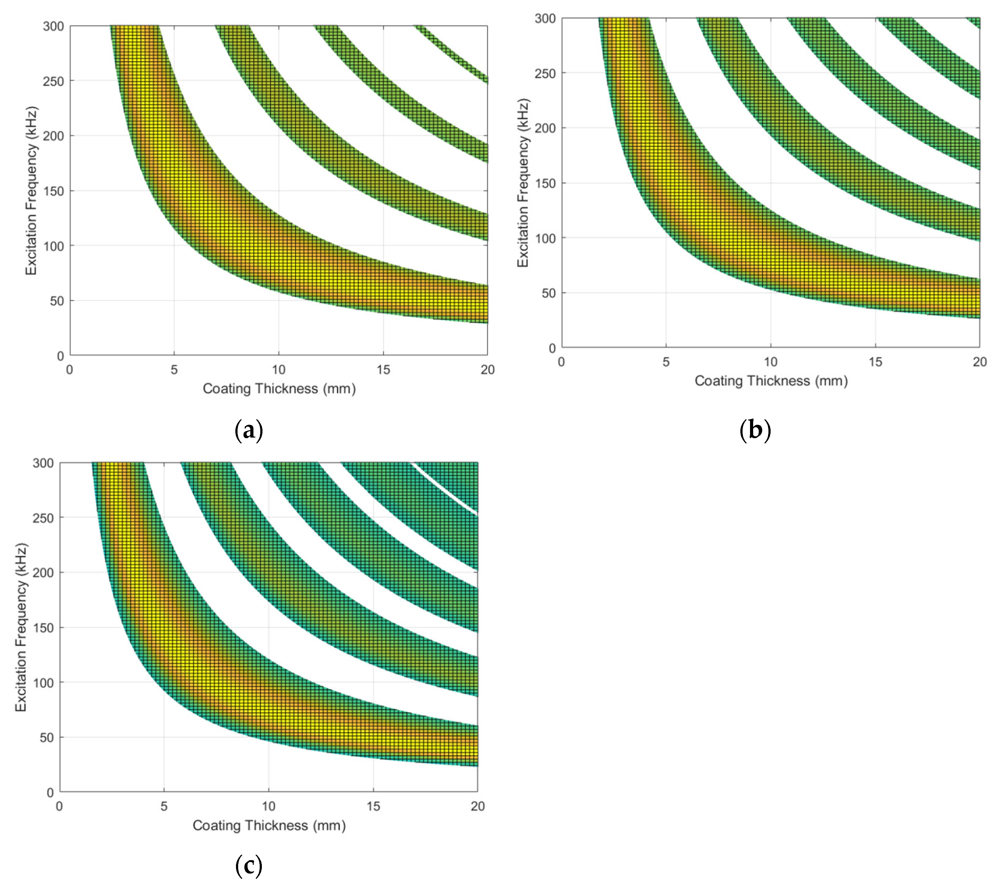
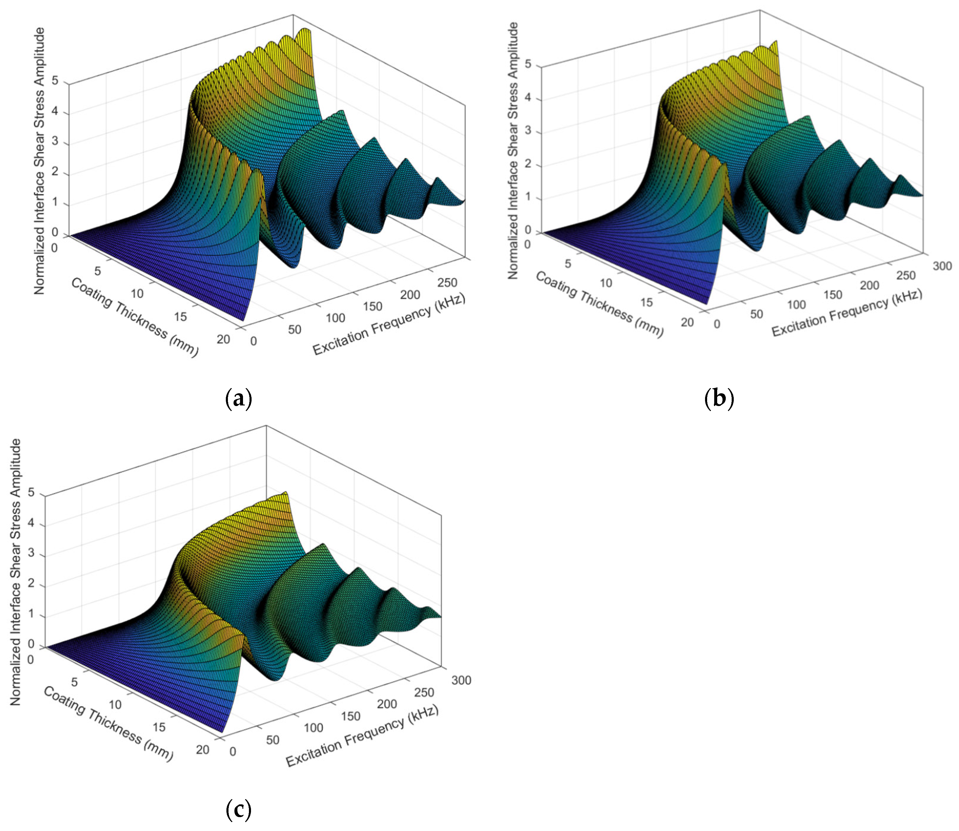
4. The Influence of Thin Coating Material on Coupling Resonance Characteristic and Interfacial Shear Delamination Interval

The amplitude of normalized interfacial shear stress is calculated in the excitation frequency domain and the coating thickness domain when the substrate is aluminum and the coating is glaze ice, rime ice, and frost in order, see Figure 5. The interval of interfacial shear stratification with [ σ ˜ 1 ] = 1.55 is determined, see Figure 6.
As illustrated in Figure 5, the coupling resonance frequency decreases with the increase of coating thickness. As the coating is glaze ice, rime ice, and frost in order, the coupling resonance frequency decreases, and the normalized interface shear stress amplitude at coupling resonance frequencies increases. The microstructure of the coating becomes more compact, the coating is more firmly bonded to the substrate, and the excitation of interfacial shear stratification becomes easier as the coating is glaze ice, rime ice, and frost in order. The smaller the shear wave velocity difference between the coating and the substrate, the higher the coupling resonance frequency of interfacial shear delamination, and the larger the excitation source strength required for interfacial shear delamination. The frost is more easily sheared and stratified from the aluminum matrix surface than glaze ice.
As illustrated in Figure 6, in the interfacial shear delamination interval, the excitation frequency increases with the decrease of coating thickness. Interfacial shear delamination intervals widen when the coating is glaze ice, rime ice, and frost in order. The lower the frequency of the elastic wave, the easier it is to propagate through the thicker coating. As the coating is glaze ice, rime ice, and frost in order, with the coating thickness increasing from 2 mm to 20 mm, the first coupling resonance frequency decreases from 300 kHz to 50 kHz, 45 kHz, and 40 kHz, respectively.
Analyzing Figure 5 and Figure 6, it is found that when the shear wave velocity of the coating increases, the coupling resonance frequency increases, the normalized interface shear stress amplitude at coupling resonance frequencies decreases, and interfacial shear delamination intervals narrow. With the increase of coating thickness, the decreasing rate of coupling resonance frequency decreases.

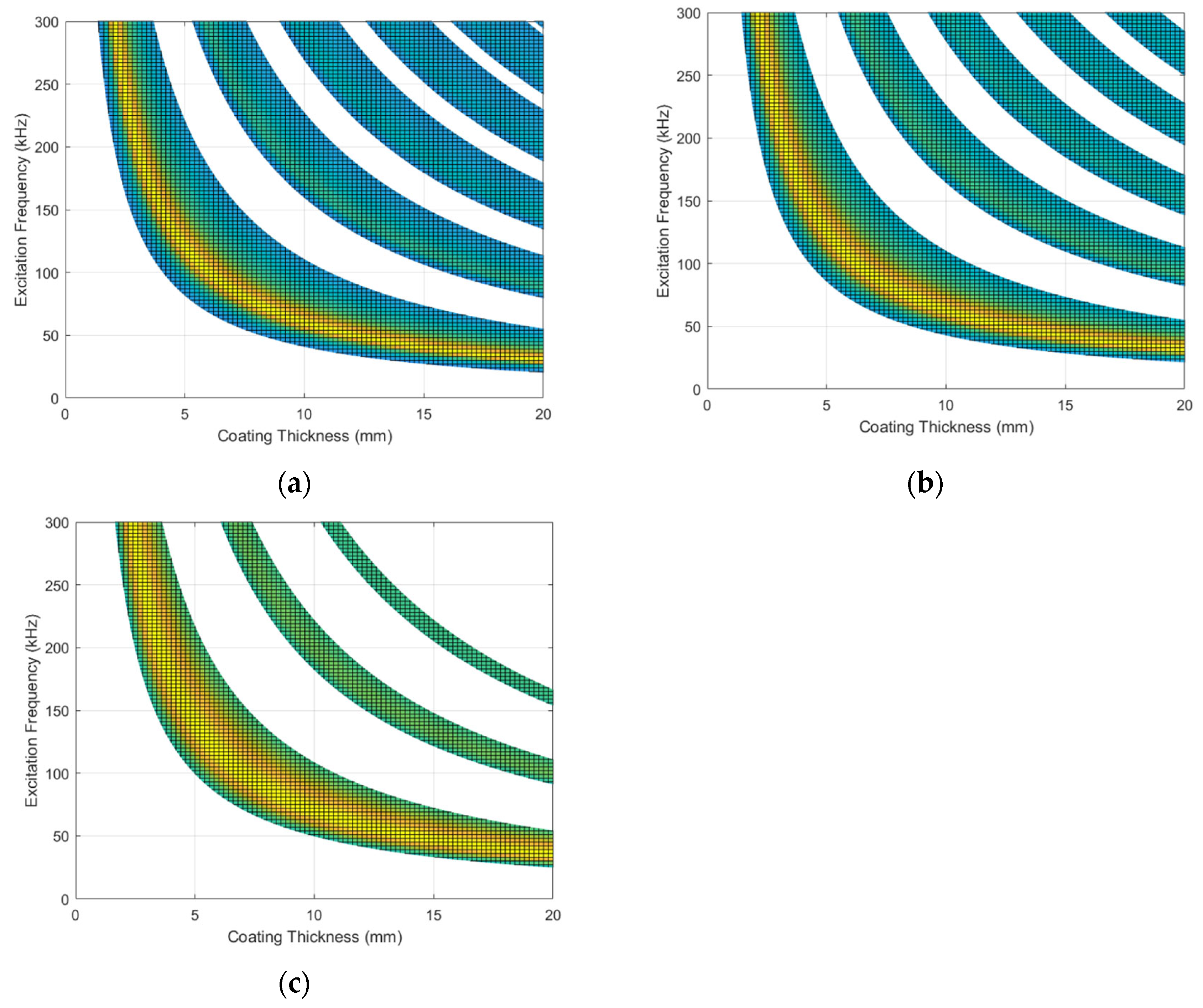
5. The Influence of Matrix Material on Coupling Resonance Characteristic and Interfacial Shear Delamination Interval

The normalized amplitude of interfacial shear stress is calculated in the excitation frequency domain and the coating thickness domain when the coating is frost and the substrate is molybdenum, steel and titanium in order, see Figure 7. The interfacial shear stratification interval with [ σ ˜ 1 ] = 1.8 is determined, see Figure 8.
As shown in Figure 7, the coupling resonance frequency decreases with the increase of coating thickness. As the substrate is molybdenum, steel and titanium in order, the coupling resonance frequency increases, and the normalized amplitude of interface shear stress at coupling resonance frequencies decreases. The excitation of interfacial shear stratification becomes more difficult as the substrate is molybdenum, steel, and titanium in order. The higher the shear wave velocity difference between the coating and the substrate, the lower the coupling resonance frequency of interfacial shear delamination, and the smaller the excitation source strength required for interfacial shear delamination. The coating on the surface of the molybdenum matrix is easier to be sheared and stratified than that on the surface of the titanium matrix.
As shown in Figure 8, in the interfacial shear delamination interval, the excitation frequency increases with the decrease of coating thickness. Interfacial shear delamination intervals become narrower and narrower when the substrate is molybdenum, steel, and titanium in order. The higher the frequency of the elastic wave, the easier it is to propagate through the thinner coating. As the substrate is molybdenum, steel, and titanium in order, with the coating thickness increasing from 2 mm to 20 mm, the first coupling resonance frequency decreases from 300 kHz to 40 kHz, 43 kHz, and 46 kHz, respectively.
Analyzing Figure 7 and Figure 8, it is found that when the shear wave velocity of the substrate increases, the coupling resonance frequency decreases, the normalized amplitude of interface shear stress at coupling resonance frequencies increases, and interfacial shear delamination intervals become wider and wider. With the increase of coating thickness, the decreasing rate of coupling resonance frequency decreases.

6. Conclusions

The forced vibration solution of interface shear stress of thin coating structures excited by horizontal shear waves is derived. The interfacial stratification necessary condition excited by the alternating shear stress is analyzed and investigated. The normalized amplitude of interfacial shear stress in the excitation frequency domain and the coating thickness domain is calculated by the adaptive Gauss–Kronrod quadrature numerical integration method. The coupling resonance mechanism of interface stratification is revealed. The coupling resonance frequency increases as the coating is frost, rime ice, and glaze ice in order or the substrate is molybdenum, steel, and titanium in order, and decreases with the increase of coating thickness. Of all the material combinations, the thin frost layer on the molybdenum matrix is the most easily stratified.

Author Contributions

Conceptualization, F.G. and J.H.W.; methodology, F.G. and L.L.; software, F.G. and S.Y.; validation, F.G. and Z.Y.; formal analysis, F.G.; investigation, F.G. and Y.Y.Z.; resources, F.G.; writing—original draft preparation, F.G.; writing—review and editing, F.G.; supervision, F.G. All authors have read and agreed to the published version of the manuscript.

Funding

Thanks for the supports of the Youth Innovation Team of Shaanxi Universities. This work was supported by Xi’an Science and Technology Bureau Project, Project Number: 21XJZZ0063.

Institutional Review Board Statement

Not applicable.

Informed Consent Statement

Not applicable.

Data Availability Statement

Not applicable.

Conflicts of Interest

The authors declare no conflict of interest.

References

  1. Pickering, S.J. Recycling technologies for thermoset composite materials-current status. Compos. Part A-Appl. Sci. Manuf. 2006, 37, 1206–1215. [Google Scholar] [CrossRef]
  2. Tan, H.; Xu, G.; Tao, T. Experimental investigation on the defrosting performance of a finned-tube evaporator using intermittent ultrasonic vibration. Appl. Energy 2015, 158, 220–232. [Google Scholar] [CrossRef]
  3. Palacios, J.; Smith, E.; Rose, J.; Royer, R. Ultrasonic de-icing of wind-tunnel impact icing. J. Aircr. 2011, 48, 1020–1027. [Google Scholar] [CrossRef]
  4. Bednarik, M.; Cervenka, M.; Lotton, P.; Simon, L. Analytical solutions for elastic SH-waves propagating through an isotropic inhomogeneous layer. Compos. Struct. 2019, 220, 875–887. [Google Scholar] [CrossRef]
  5. Golub, M.V.; Fomenko, S.I.; Bui, T.Q.; Zhang, C.; Wang, Y.S. Transmission and band gaps of elastic SH waves in functionally graded periodic laminates. Int. J. Solids Struct. 2012, 49, 344–354. [Google Scholar] [CrossRef] [Green Version]
  6. Mardanshahi, A.; Shokrieh, M.M.; Kazemirad, S. Identification of matrix cracking in cross-ply laminated composites using Lamb wave propagation. Compos. Struct. 2020, 235, 111790. [Google Scholar] [CrossRef]
  7. Zhu, F.; Pan, E.; Qian, Z. Waves in a generally anisotropic viscoelastic composite laminated bilayer: Impact of the imperfect interface from perfect to complete delamination. Int. J. Solids Struct. 2020, 202, 262–277. [Google Scholar] [CrossRef]
  8. Rose, J.L. Ultrasonic waves in solid media. Cambridge University Press 1999, 3, 24–25. [Google Scholar] [CrossRef]
  9. He, J.H. Generalized variational principles for buckling analysis of circular cylinders. Acta Mech. 2020, 231, 899–906. [Google Scholar] [CrossRef]
  10. He, J.H. Hamilton’s principle for dynamical elasticity. Appl. Math. Lett. 2017, 72, 65–69. [Google Scholar] [CrossRef]
  11. Al-Furjan, M.S.H.; Habibi, M.; won Jung, D.; Sadeghi, S.; Safarpour, H.; Tounsi, A.; Chen, G. A computational framework for propagated waves in a sandwich doubly curved nanocomposite panel. Eng. Comput. 2022, 38, 1679–1696. [Google Scholar] [CrossRef]
  12. He, J.H. Variational iteration method for autonomous ordinary differential systems. Appl. Math. Comput. 2000, 114, 115–123. [Google Scholar] [CrossRef]
  13. He, J.H.; El-Dib, Y.O. Homotopy perturbation method for Fangzhu oscillator. J. Math. Chem. 2020, 58, 2245–2253. [Google Scholar] [CrossRef]
  14. Anjum, N.; He, J.H. Homotopy perturbation method for N/MEMS oscillators. Math. Methods Appl. Sci. 2020, 1–15. [Google Scholar] [CrossRef]
  15. Debnath, L.; Bhatta, D. Integral Transforms and Their Applications; CRC Press: Boca Raton, FL, USA, 2014. [Google Scholar]
  16. Rungger, I.; Droghetti, A.; Stamenova, M. Non-equilibrium Green’s Function Methods for Spin Transport and Dynamics. In Handbook of Materials Modeling: Methods: Theory and Modeling; Springer: Cham, Switzerland, 2020; pp. 957–983. [Google Scholar]
  17. Polyanin, A.D.; Zhurov, A.I. Separation of variables in PDEs using nonlinear transformations: Applications to reaction–diffusion type equations. Appl. Math. Lett. 2020, 100, 106055. [Google Scholar] [CrossRef]
  18. Ali, A. The Transform of Partial Differential Equations to Ordinary Differential Equations by Using Integral Transforms and Separation of Variables Methods; University of Gezira: Wad Medani, Sudan, 2017. [Google Scholar]
  19. Yilmaz, C.; Topal, S.; Ali, H.Q. Non-destructive determination of the stiffness matrix of a laminated composite structure with lamb wave. Compos. Struct. 2020, 237, 111956. [Google Scholar] [CrossRef]
  20. Ding, L.; Zhu, H.P.; Wu, L. Analysis of mechanical properties of laminated rubber bearings based on transfer matrix method. Compos. Struct. 2017, 159, 390–396. [Google Scholar] [CrossRef]
  21. Knopoff, L. A matrix method for elastic wave problems. Bull. Seismol. Soc. Am. 1964, 54, 431–438. [Google Scholar] [CrossRef]
  22. Gao, J.; Lyu, Y.; Zheng, M. Modeling guided wave propagation in multi-layered anisotropic composite laminates by state-vector formalism and the Legendre polynomials. Compos. Struct. 2019, 228, 111319. [Google Scholar] [CrossRef]
  23. Ogilvy, J.A. A model for the ultrasonic inspection of composite plates. Ultrasonics 1995, 33, 85–93. [Google Scholar] [CrossRef]
  24. Li, X.; Wang, H.; Li, G. Reanalysis assisted metaheuristic optimization for free vibration problems of composite laminates. Compos. Struct. 2018, 206, 380–391. [Google Scholar] [CrossRef]
  25. Tuan, H.S.; Ponamgi, S.R. Excitation of Love Waves in a Thin Film Layer by a Line Source. IEEE Trans. Sonics Ultrason. 1972, 19, 9–14. [Google Scholar] [CrossRef]
  26. Hashimoto, K.; Yamaguchi, H. Excitation and propagation of shear-horizontal-type surface and bulk acoustic waves. IEEE Trans. Ultrason. Ferr. 2001, 48, 1181–1188. [Google Scholar] [CrossRef] [PubMed]
  27. Singh, A.K.; Singh, S.; Kumari, R.; Ray, A. Impact of point source and mass loading sensitivity on the propagation of an SH wave in an imperfectly bonded FGPPM layered structure. Acta Mech. 2020, 231, 2603–2627. [Google Scholar] [CrossRef]
  28. Adachi, K.; Saiki, K.; Sato, H.; Ito, T. Ultrasonic frost suppression. Jpn. J. Appl. Phys. 2003, 42, 682–685. [Google Scholar] [CrossRef]
  29. Wang, Z. Recent progress on ultrasonic de-icing technique used for wind power generation, high-voltage transmission line and aircraft. Energy Build. 2017, 140, 42–49. [Google Scholar] [CrossRef]
  30. Palacios, J.; Smith, E.; Rose, J.; Royer, R. Instantaneous de-icing of freezer ice via ultrasonic actuation. AIAA J. 2011, 49, 1158–1167. [Google Scholar] [CrossRef] [Green Version]
  31. Li, D.; Chen, Z. Experimental study on instantaneously shedding frozen water droplets from cold vertical surface by ultrasonic vibration. Exp. Therm. Fluid Sci. 2014, 53, 17–25. [Google Scholar] [CrossRef]
  32. Tan, H.; Tao, T.; Xu, G. Experimental study on defrosting mechanism of intermittent ultrasonic resonance for a finned-tube evaporator. Exp. Therm. Fluid Sci. 2014, 52, 308–317. [Google Scholar] [CrossRef]
  33. Kalkowski, M.K.; Waters, T.P.; Rustighi, E. Delamination of surface accretions with structural waves: Piezo-actuation and power requirements. J. Intell. Mater. Syst. Struct. 2017, 28, 1454–1471. [Google Scholar] [CrossRef]
  34. Overmeyer, A.; Palacios, J.; Smith, E. Ultrasonic de-icing bondline design and rotor ice testing. AIAA J. 2013, 51, 2965–2976. [Google Scholar] [CrossRef]
  35. Budinger, M.; Pommier-Budinger, V.; Napias, G.; da Silva, A.C. Ultrasonic Ice Protection Systems: Analytical and Numerical Models for Architecture Tradeoff. J. Aircr. 2016, 53, 680–690. [Google Scholar] [CrossRef] [Green Version]
  36. Venna, S.V.; Lin, Y.J. Mechatronic development of self-actuating in-flight deicing structures. IEEE-ASME Trans. Mech. 2006, 11, 585–592. [Google Scholar] [CrossRef]
  37. Venna, S.V.; Lin, Y.J.; Botura, G. Piezoelectric transducer actuated leading edge de-icing with simultaneous shear and impulse forces. J. Aircr. 2007, 44, 509–515. [Google Scholar] [CrossRef]
  38. Zeng, J.; Song, B. Research on experiment and numerical simulation of ultrasonic de-icing for wind turbine blades. Renew. Energy 2017, 113, 706–712. [Google Scholar] [CrossRef]
  39. Wang, Z.; Xu, Y.; Su, F.; Wang, Y. A light lithium niobate transducer for the ultrasonic de-icing of wind turbine blades. Renew. Energy 2016, 99, 1299–1305. [Google Scholar] [CrossRef]
  40. Wang, Y.; Xu, Y.; Lei, Y. An effect assessment and prediction method of ultrasonic de-icing for composite wind turbine blades. Renew. Energy 2018, 118, 1015–1023. [Google Scholar] [CrossRef]
  41. Habibi, H.; Cheng, L.; Zheng, H.; Kappatos, V.; Selcuk, C.; Gan, T.H. A dual de-icing system for wind turbine blades combining high-power ultrasonic guided waves and low-frequency forced vibrations. Renew. Energy 2015, 83, 859–870. [Google Scholar] [CrossRef] [Green Version]
  42. Wang, Y.; Xu, Y.; Huang, Q. Progress on ultrasonic guided waves de-icing techniques in improving aviation energy efficiency. Renew. Sust. Energy Rev. 2017, 79, 638–645. [Google Scholar] [CrossRef]
  43. Wang, D.; Tao, T.; Xu, G.; Luo, A.; Kang, S. Experimental study on frosting suppression for a finned-tube evaporator using ultrasonic vibration. Exp. Therm. Fluid Sci. 2012, 36, 1–11. [Google Scholar] [CrossRef]
  44. Tan, H.; Zhang, X.; Zhang, L. Ultrasonic influence mechanism of a cold surface frosting process and an optimised defrosting technique. Appl. Therm. Eng. 2019, 153, 113–127. [Google Scholar] [CrossRef]
  45. Guo, F.; Wu, J.H. Analytical solution and coupling resonance mechanism of interface delamination of composite laminates excited by ultrasonic shear horizontal waves. Compos. Struct. 2021, 276, 114583. [Google Scholar] [CrossRef]
  46. Guo, F.; Wu, J.H. Coupling resonance mechanism of interfacial stratification of sandwich plate structures excited by SH waves. J. Low Freq. Noise Vib. Act. Control 2021, 40, 1166–1193. [Google Scholar] [CrossRef]
  47. Guo, F.; Wu, J.H. Coupling resonance mechanism of interfacial fatigue stratification of adhesive and/or welding butt joint structures excited by horizontal shear waves. Int. J. Mod. Phys. B 2021, 35, 2150096. [Google Scholar] [CrossRef]
  48. Ramani, R.; Saparia, A.; Markna, J. Effect of Nanocoating (CuO Nanoparticles) on the Performance of Solar Evacuated Tube. J. Sustain. Mater. Process. Manag. 2022, 2, 64–71. [Google Scholar] [CrossRef]
  49. Gander, W.; Gautschi, W. Adaptive quadrature—Revisited. BIT Numer. Math. 2000, 40, 84–101. [Google Scholar] [CrossRef]
  50. Calvetti, D.; Golub, G.; Gragg, W. Computation of Gauss-Kronrod quadrature rules. Math. Comput. 2000, 69, 1035–1052. [Google Scholar] [CrossRef] [Green Version]
  51. Johnson, R.W. Algorithm 988: AMGKQ: An Efficient Implementation of Adaptive Multivariate Gauss-Kronrod Quadrature for Simultaneous Integrands in Octave/MATLAB. ACM Trans. Math. Softw. (TOMS) 2018, 44, 1–19. [Google Scholar] [CrossRef]
  52. Rahman, A.; Huang, H.; Ai, C. Fatigue performance of interface bonding between asphalt pavement layers using four-point shear test set-up. Int. J. Fatigue 2019, 121, 181–190. [Google Scholar] [CrossRef]
Figure 1. Thin coating structures.
Coatings 12 01509 g001
Figure 2. The analytical result and the finite element result of normalized interfacial shear stress amplitude in the excitation frequency domain as the frost coating thickness on the aluminum substrate is 5 mm, and the interfacial shear delamination interval with [ σ ˜ 1 ] = 2 .
Coatings 12 01509 g002
Figure 3. The analytical result and the finite element result of normalized interfacial shear stress amplitude in the coating thickness domain when the excitation frequency is 80 kHz and the coating on the aluminum substrate is frost, and the interfacial shear delamination interval with [ σ ˜ 1 ] = 2 .
Coatings 12 01509 g003
Figure 4. The finite element model (a), the displacement component uy in the x-z plane (b), the horizontal shear stress σzy in the x-z plane (c), and the horizontal shear stress σzy at the interface (d) at 130 kHz as the frost coating thickness on the aluminum substrate is 5 mm.
Coatings 12 01509 g004
Figure 5. The normalized amplitude of interfacial shear stress in the excitation frequency domain and the coating thickness domain when the substrate is aluminum and the coating is glaze ice (a), rime ice (b) and frost (c).
Coatings 12 01509 g005
Figure 6. Intervals of interfacial shear delamination in the excitation frequency domain and the coating thickness domain as [ σ ˜ 1 ] = 1.55 , the substrate is aluminum and the coating is glaze ice (a), rime ice (b) and frost (c).
Coatings 12 01509 g006
Figure 7. The normalized amplitude of interfacial shear stress in the excitation frequency domain and the coating thickness domain as the coating is frost and the substrate is molybdenum (a), steel (b) and titanium (c).
Coatings 12 01509 g007
Figure 8. Intervals of interfacial shear delamination in the excitation frequency domain and the coating thickness domain as [ σ ˜ 1 ] = 1.8 , the coating is frost and the substrate is molybdenum (a), steel (b), and titanium (c).
Coatings 12 01509 g008
Table 1. Material parameters.
MaterialYoung’s Modulus (GPa)Poisson’s RatioDensity (kg/m3)Shear Modulus (GPa)Shear Wave Velocity (m/s)
Frost7.7590.3438002.6611900
Rime Ice8.7590.3379003.2761907
Glaze Ice9.7590.3319503.6661964
Aluminum69.40.337270023.43140
Titanium1020.35460037.7782866
Steel205.00.287850803194
Molybdenum297.30.29710,200114.33350
Publisher’s Note: MDPI stays neutral with regard to jurisdictional claims in published maps and institutional affiliations.

