Article

A Split-Ring Resonator-Loaded Honeycomb Sandwich Structure for Broadband Microwave Absorption

1
State-Owned Wuhu Machinery Factory, Wuhu 241000, China
2
Science and Technology on Thermostructural Composite Materials Laboratory, Northwestern Polytechnical University, Xi’an 710072, China
*
Author to whom correspondence should be addressed.
Coatings 2022, 12(11), 1706; https://doi.org/10.3390/coatings12111706
Submission received: 13 October 2022 / Revised: 2 November 2022 / Accepted: 8 November 2022 / Published: 9 November 2022
(This article belongs to the Special Issue Micro/Nanomaterials for Heat Transfer, Energy Storage and Conversion)

Abstract

:
Split-ring resonators are excellent left-handed metamaterials for significant electromagnetic coupling behavior. In this work, a split-ring resonator prepared with Ni-doped zeolitic imidazolate framework-67/epoxy resin (ZIF-67/ER) was embedded in the top layer to optimize microwave absorption efficiency in the 2–4 GHz frequency band. The Ni-doped ZIF-67/epoxy resin served as the bottom layer to improve microwave absorption efficiency in the 4–8 GHz frequency band. Honeycomb with a conductive carbon black coating served as the middle layer to generate electromagnetic loss for the overall frequency band. Based on the composite structure integration technology, RL < −10 dB was realized under the oblique incidence of 0–70 degrees. Both simulation and experiments indicate that a split-ring resonator made of lossy material can be an effective strategy to broaden the effective absorption bandwidth and increase the corresponding structure’s insensitivity to polarization and the incidence angle of microwave.

1. Introduction

The aramid honeycomb sandwich structure (AHSS) plays a structural–function–integration role in stealth aircraft due to its high flexural strength/mass ratio and easy-to-adjust electrical properties [1,2]. However, the rapid development in omnidirectional radar detection technology has required the AHSS to have a wider effective microwave-absorbing bandwidth as well as insensitivity to polarization and the microwave incidence angle to effectively reduce radar cross-section (RCS) [3,4,5,6]. Therefore, obtaining high-performance radar-absorbing materials/structures through composition, structure and preparation is a major issue.
In order to meet the great challenge of radar detection, many researchers are working to make stealth shields stronger, specifically through composition and microstructure design using metals and alloys, carbon materials, metal–carbon composite materials, ceramics and composites, polymers, etc. [7,8,9,10,11]. For example, Zeng et al. [12] obtained hierarchical cobalt selenides using a hydrothermal method followed by high-temperature salination, which can be used as highly efficient wave absorbers with a tunable frequency response. Obviously, the designs of microstructure and composition are of great help in improving the absorbing performance. Mesoscopic and macroscopic structural design can be achieved with 2D frequency selective surfaces, a 3D honeycomb sandwich structure and the integration of various absorbing structures [13,14,15,16,17,18]. Zhou et al. [5] proposed a flexible broadband metamaterial absorber based on sandwiched cylindrical water resonators prepared via 3D printing. Low- and high-frequency cooperative electromagnetic absorption at 4–40 GHz is achieved with excellent oblique incidence insensitivity. However, it is difficult to realize broadband microwave absorption only via composition and microstructure design. At the same time, the strong electromagnetic coupling behavior between the integrated multiple absorbing structures may reduce the intrinsic microwave absorption efficiency of each structure. Therefore, it is necessary to design a broadband microwave-absorbing structure that is insensitive to polarization and incidence angle of microwave.
In this paper, a split-ring resonator was made with Ni-doped ZIF-67/epoxy resin embedded in the top layer to optimize microwave absorption efficiency in the 2–4 GHz frequency band. At the same time, the Ni-doped ZIF-67/epoxy resin served as the bottom layer to improve microwave absorption efficiency in the 4–8 GHz frequency band. Honeycomb with conductive carbon black coating served as the middle layer to generate electromagnetic loss for the overall frequency band. On one hand, the split-ring resonator generated electromagnetic resonance in the 2–4 GHz frequency band. On the other hand, the discontinuous ring periodic structure could effectively reduce impedance mismatch in the 4–18 GHz frequency band. Therefore, the effective absorption bandwidth covered the entire 2–18 GHz frequency band. Interestingly, microwave absorption efficiency is insensitive to polarization and the incidence angle, which can effectively reduce the stealth performance degradation of aircraft with large curvature.

2. Experiment and Simulation Method

2.1. Material Fabrication

Figure 1 shows a schematic of a unit cell in the designed honeycomb sandwich structure. The top panel layer in Figure 1a was formed by embedding a split-ring metasurface in SiO2-fiber-reinforced epoxy resin (SiO2f/ER). The split-ring periodic structure was prepared by mixing Ni-doped ZIF-67 with epoxy resin using a high-speed mixer. The mass fraction of Ni-doped ZIF-67 (Nanjing XFNANO Materials Tech Co., Ltd. and the corresponding product number is XFF15) was 25%. The honeycomb in Figure 1b was prepared using the dip-coating method, and the mass fraction of carbon black (the corresponding product number is XF080) in the corresponding carbon black/ER impregnation solution was 28%, which could be determined by the honeycomb weight gain. The bottom panel layer prepared with Ni-doped ZIF-67/ER was finally bonded with the top panel layer and honeycomb using an adhesive film whose thickness was 0.2 mm.

2.2. Characterization, Simulation and Calculation

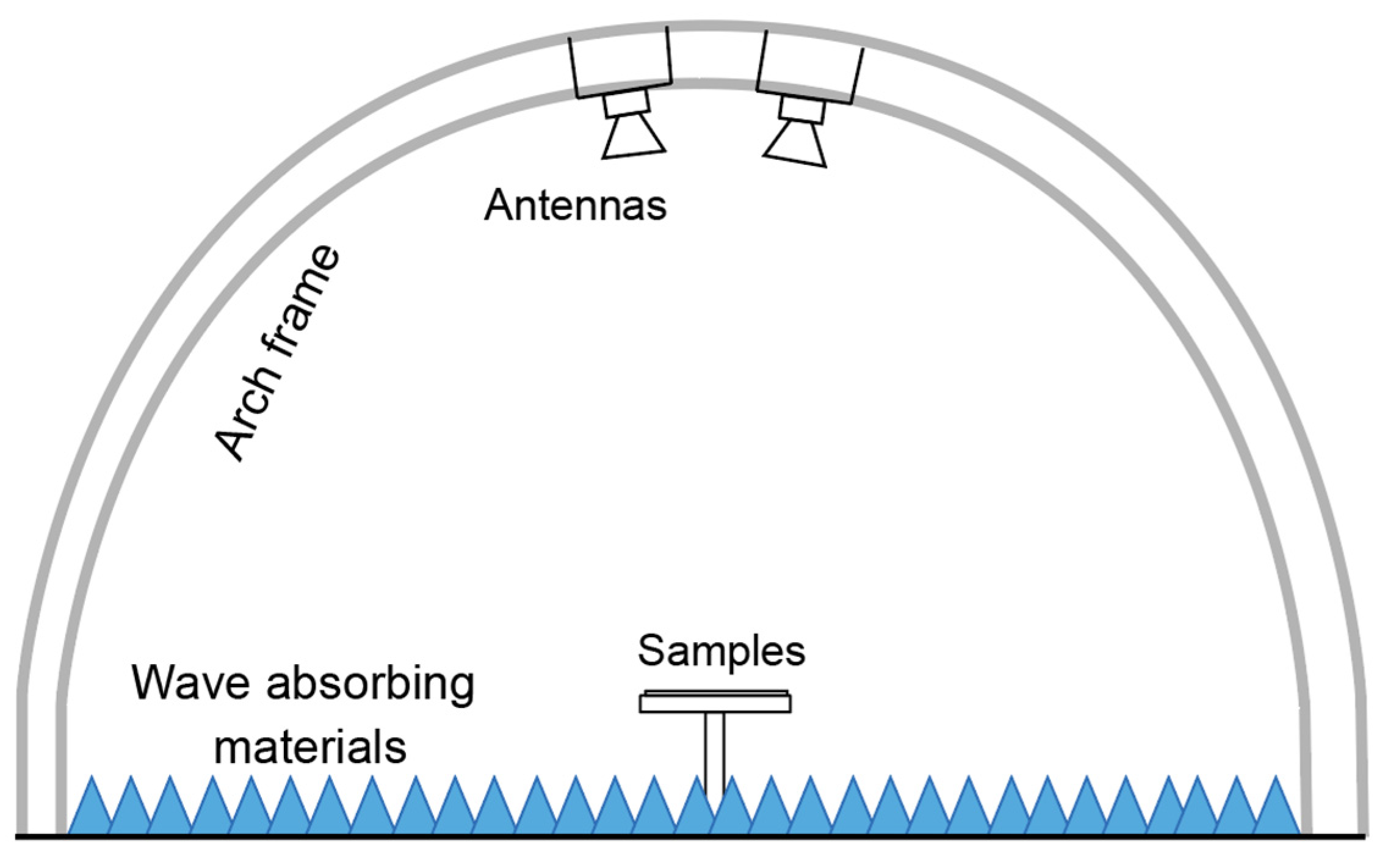
The respective relative effective complex permittivity and permeability of SiO2f/ER, honeycomb and Ni-doped ZIF-67/ER were determined with a vector network analyzer (VNA, N5234A, Agilent; USA) in the 2–18 GHz frequency band using a rectangular waveguide. Rectangular waveguides can be used for such measurements only in the specified ranges (S, C, X, Ku), and the frequency testing ranges and dimensions of samples are listed in Table 1. The reflection loss in different microwave incidence angles and polarization directions in the 2–18 GHz frequency band were measured using the free-space method. The antenna was manufactured by Q-par Angus LTD, and the size of the test sample was 300 mm ×300 mm. The sample rating was set at 3201 points, and a schematic illustration of the arch method is shown in Figure 2. CST Microwave Studio based on the finite integration technique was used to perform numerical simulation on the split-ring resonator-loaded honeycomb sandwich structure.
Transmission line theory and the metal backplane model were used to calculate reflection loss (RL) and the corresponding impedance of the honeycomb sandwich structure, which can be expressed as [19,20]:
R L = 20 log 10 | Z i Z 0 Z i + Z 0 |
Z 1 = μ 1 / ε 1 tanh [ j 2 π f d 1 μ 1 ε 1 / c ]
Z 2 = μ 2 / ε 2 Z 1 + μ 2 / ε 2 tanh [ j 2 π f d 2 μ 2 ε 2 / c ] μ 2 / ε 2 + Z 1 tanh [ j 2 π f d 2 μ 2 ε 2 / c ]
where Zi is the normalized impedance of layer i from the bottom up, and εi and μi are the relative complex permittivity and permeability of layer i, respectively. di is the thickness of layer i, f is the frequency of the microwave, and c represents the speed of light in the free space.

3. Results and Discussion

3.1. Microwave Absorption Efficiency of Honeycomb with Carbon Black/ER Coating

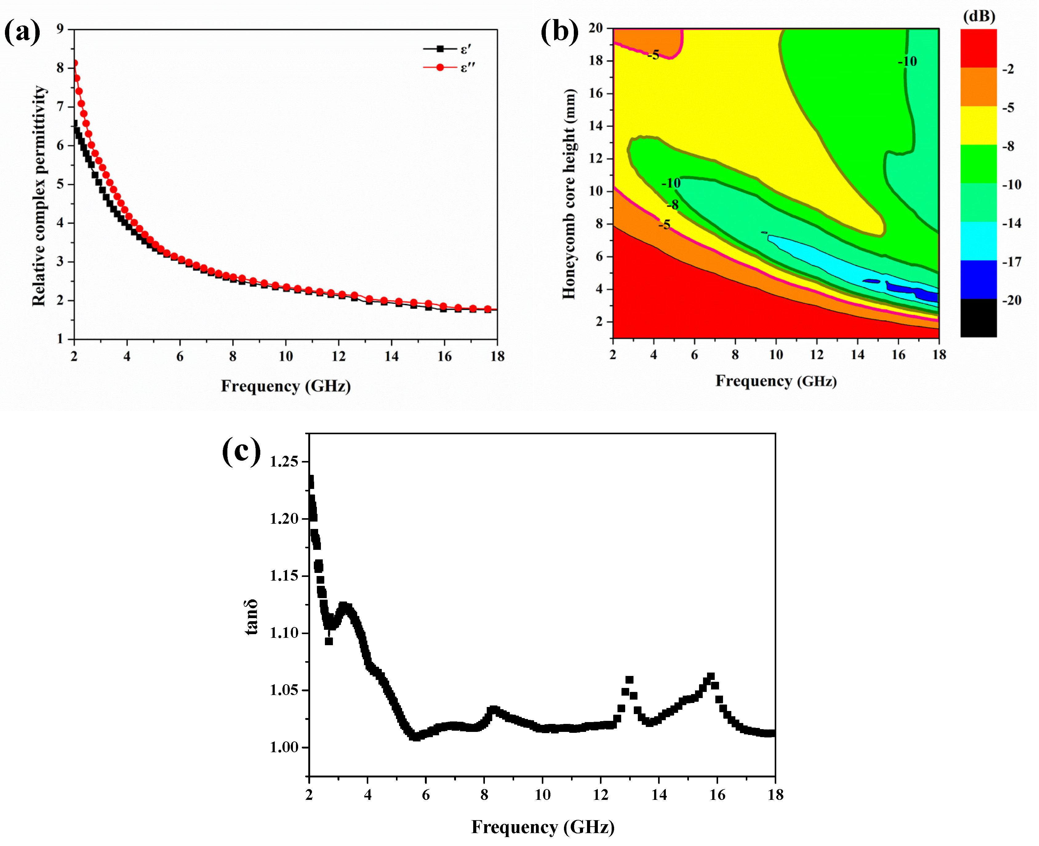
Figure 3 exhibits the relative complex permittivity and corresponding RL of honeycomb with a carbon black/ER coating in the frequency range of 2–18 GHz. The relative complex permittivity in Figure 3a exhibited an excellent frequency dispersion effect, indicating a significant hysteresis effect of polarized charges in the alternating electromagnetic field. At the same time, the value of the imaginary part of permittivity was close to the real part of permittivity, indicating the honeycomb can effectively consume microwave energy.
The RL of the honeycomb was calculated via Equations (1) and (2) for different thicknesses and frequencies, as seen in Figure 3b, indicating the target honeycomb thickness for an optimal loss in microwave is 10–14 mm. Figure 4 exhibits the real and imaginary parts of impedance at different honeycomb thicknesses; the imaginary part’s peak frequency corresponded to the midpoint of the frequency band where the real part’s value suddenly dropped. At the same time, when the thickness increased, the peak frequency shifted to lower frequencies, implying the resonance behavior is determined by the quarter-wavelength matching mechanism. The honeycomb with a thickness of 12 mm had excellent impedance matching performance at different frequency points. Next, we will further optimize the honeycomb with a height of 12 mm.

3.2. Microwave Absorption Efficiency of Honeycomb with Bottom Panel Layer

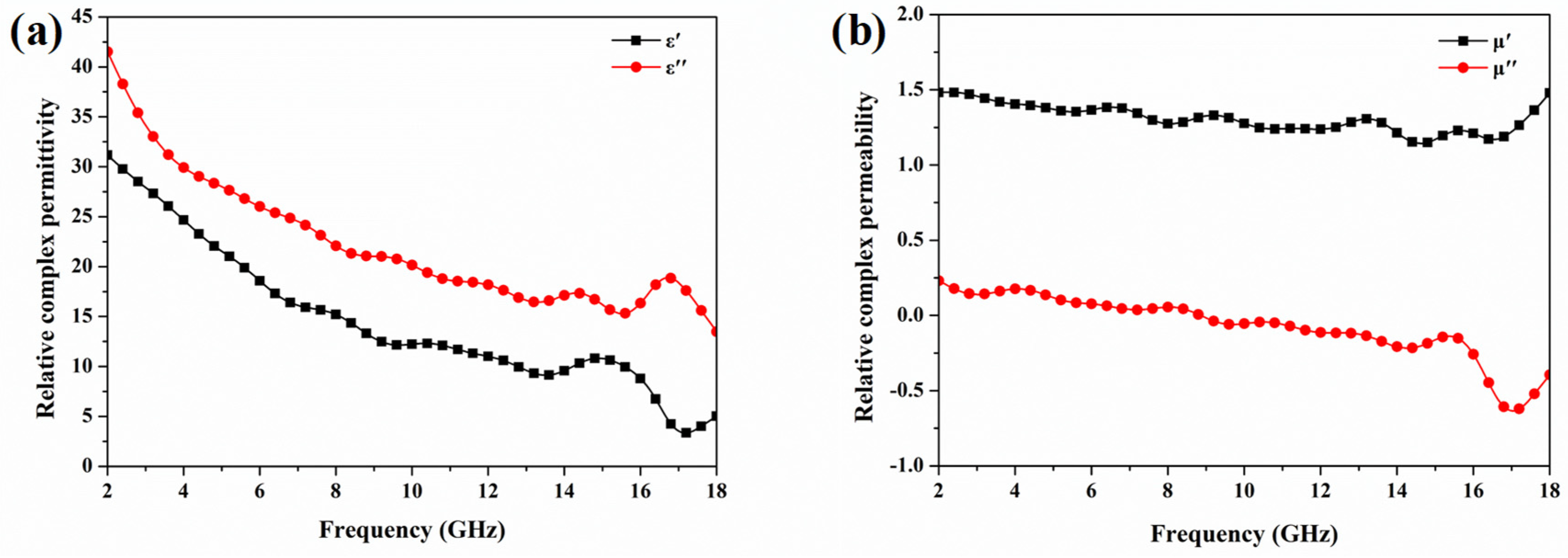
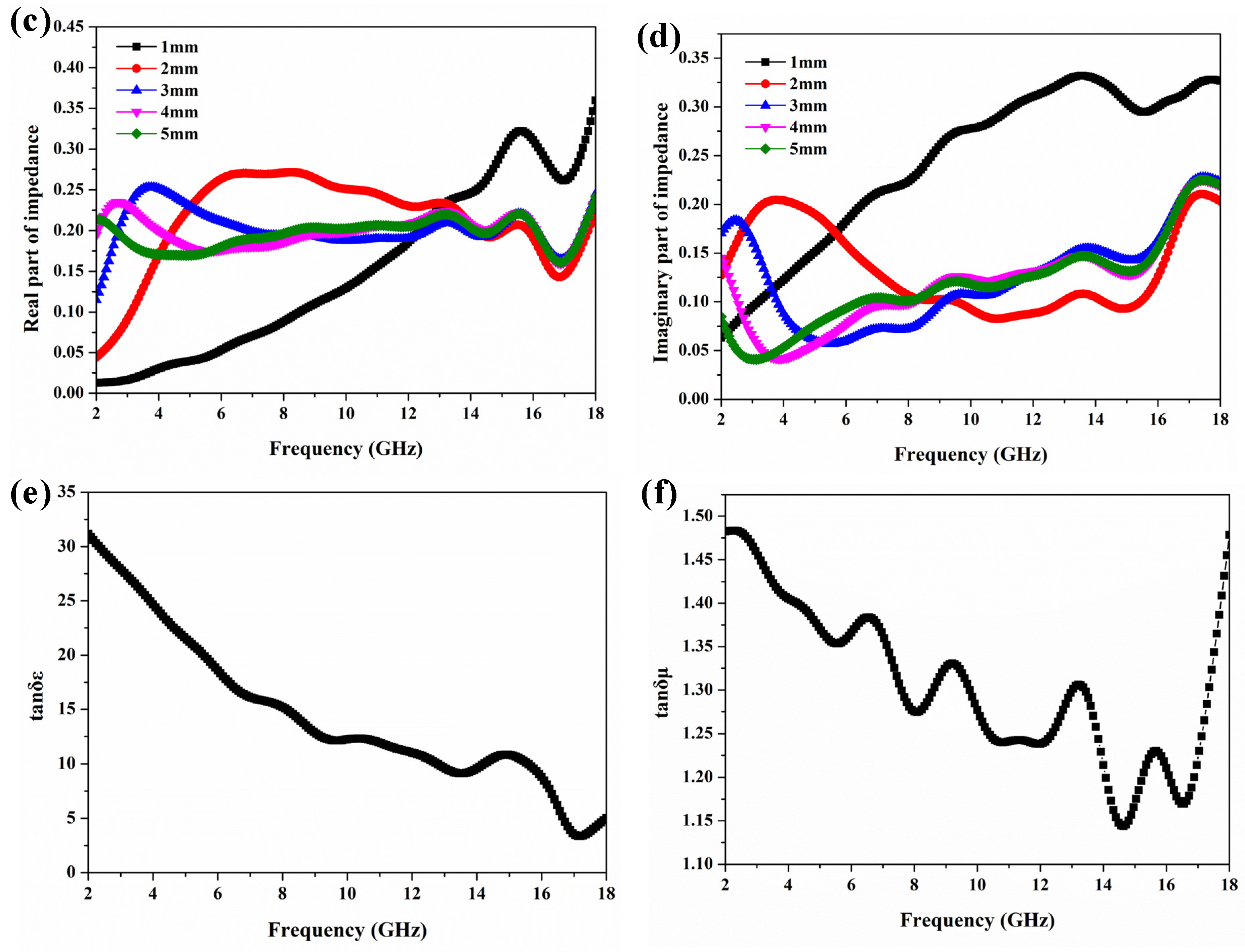
Ni-doped ZIF-67/ER was selected as the bottom panel layer. Figure 5 exhibits the electromagnetic parameters of Ni-doped ZIF-67/ER. The imaginary part of permittivity was much larger than the real part of permittivity, indicating the Ni-doped ZIF-67/ER layer exhibits excellent electromagnetic loss. Both the real and imaginary parts of permittivity exhibited an excellent frequency dispersion effect, implying the potential of broadband microwave absorption. The introduction of Ni made the bottom panel layer magnetic, which helped to improve the overall impedance matching performance according to Equations (2) and (3). It is noted that μ″ showed negative values for Ni-doped ZIF-67/ER within 10–18 GHz. According to the Maxwell equations, the alternating electric field and magnetic field can be transformed into each other. In this case, the dipole or interface resonance generates an oscillating electric field, and this electric field consequently induces an additional alternating magnetic field superposing on the oscillating magnetic moments under a high-frequency wave. The negative permeability will occur when the induced magnetic field is stronger than the latter.
Figure 6 exhibits the impedance and RL for a 12 mm honeycomb with different bottom panel layer thicknesses. The thickness of the bottom panel layer had a significant effect on the microwave absorption efficiency in the 2–8 GHz frequency band. Specifically, as the thickness of the bottom panel layer increased, the real part of impedance decreased and the imaginary part of impedance increased. The real part of impedance reflects the ability of a material to consume microwave energy, and the imaginary part of impedance reflects the ability to store charge. Therefore, when the thickness of the bottom panel layer increased, the ability to transport charge decreased, which means more microwave reflection and the corresponding impedance matching performance deteriorated. However, in the 4–8 GHz frequency band, as the thickness of the bottom panel layer increased, the impedance exhibited the opposite compared with the 2–4 GHz frequency band, indicating there is an optimal value for the bottom panel layer thickness. RL peak frequency moved to a lower frequency when the thickness increased, which satisfied the quarter-wavelength matching mechanism, and the corresponding RL peak intensity diminished with increasing thickness.
When the thickness of the bottom panel layer was 2.5 mm, the value of RL decreased with the increase in frequency. Next, we fixed the bottom panel layer thickness at 2.5 mm and further optimized the honeycomb sandwich structure.

3.3. Microwave Absorption of Split-Ring Resonator-Loaded Honeycomb Sandwich Structure

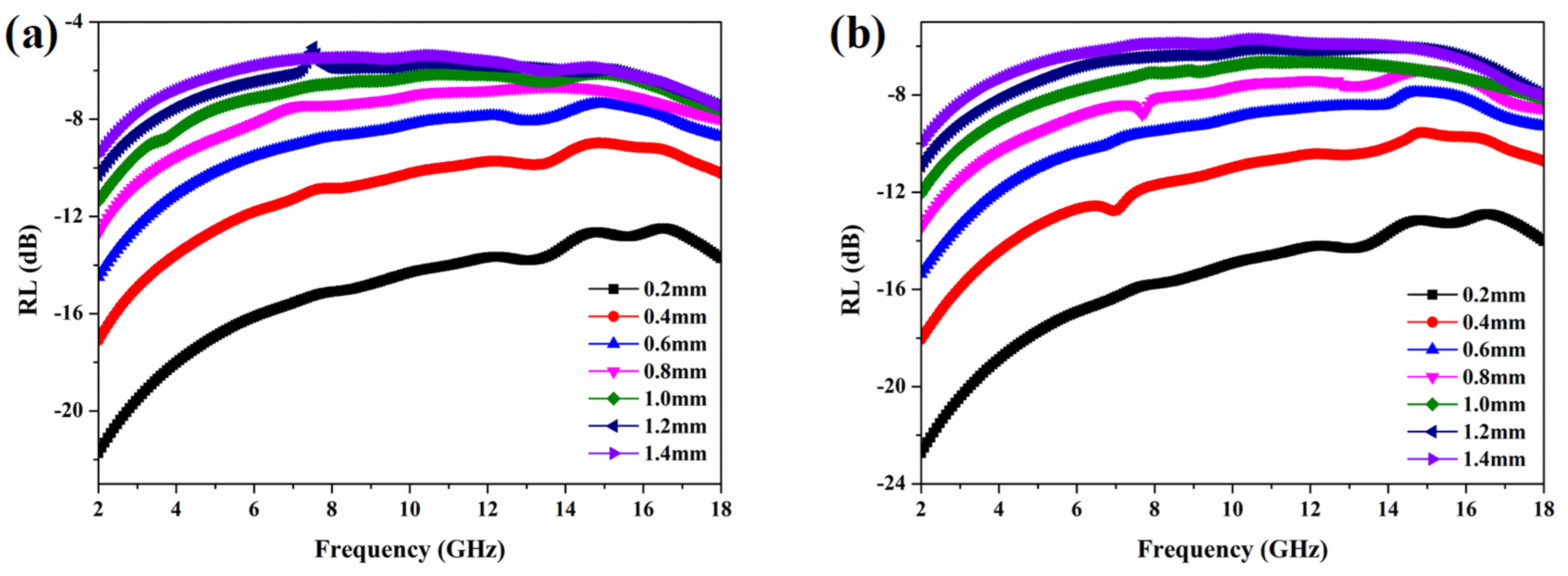
In order to optimize the microwave absorption efficiency of the honeycomb sandwich structure at 2–4 GHz, a split-ring metasurface was designed according to Figure 1a. The corresponding RL of the split-ring metasurface at different thicknesses in TE and TM modes is shown in Figure 7. Obviously, when the thickness was thinner, the split-ring metasurface more easily achieved both impedance matching and electromagnetic attenuation. According to Equation (2), a large dielectric value requires a thin thickness to meet impedance matching, which is confirmed by the test results. The designed split-ring metasurface could effectively consume microwave energy at 2–4 GHz and reflection loss insensitive to polarization for the overall frequency band.
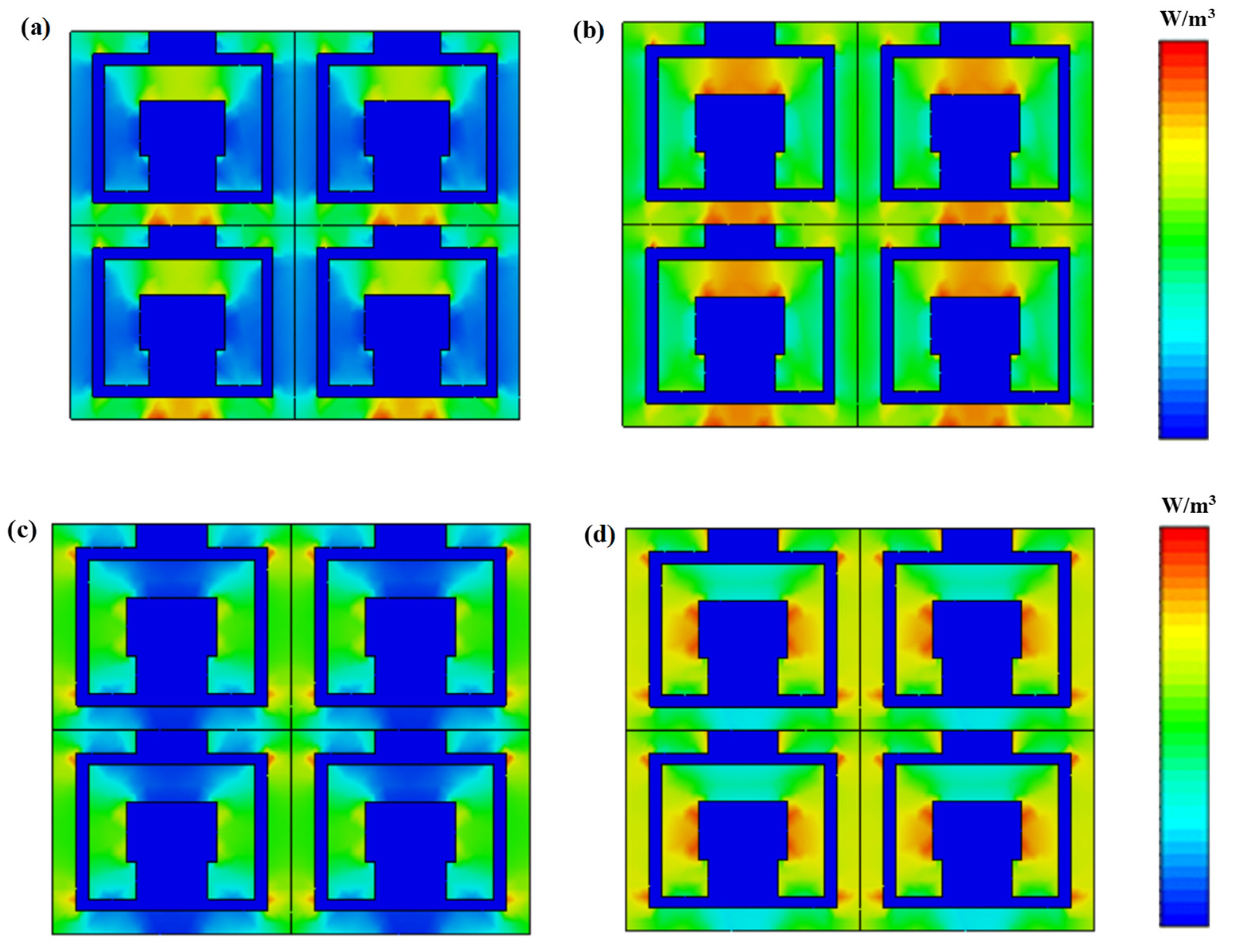
Figure 8 exhibits simulated distributions of power loss density of the split-ring metasurface in TE and TM modes at 3 GHz and 14 GHz, respectively. In the TE mode, the electric field direction was parallel to the split-ring gap, and the corresponding power loss density was most pronounced near the gap. An interrupt-conduction phenomenon occurred near the gap. At the gap, the charge transmission path was interrupted, resulting in charge concentration. The concentrated charge was released in the conduction region, thereby causing an effective loss in microwave energy. The interrupt-conduction phenomenon existed in both low-frequency (3 GHz) and high-frequency bands (14 GHz), which further confirms that the split-ring metasurface can effectively consume microwave energy at low-frequency bands while taking into account the impedance matching at high-frequency bands. Interestingly, in the TM mode, the power loss density was most pronounced in the ring parallel to the direction of the electric field for the overall frequency band, indicating an effective loss in microwave energy.
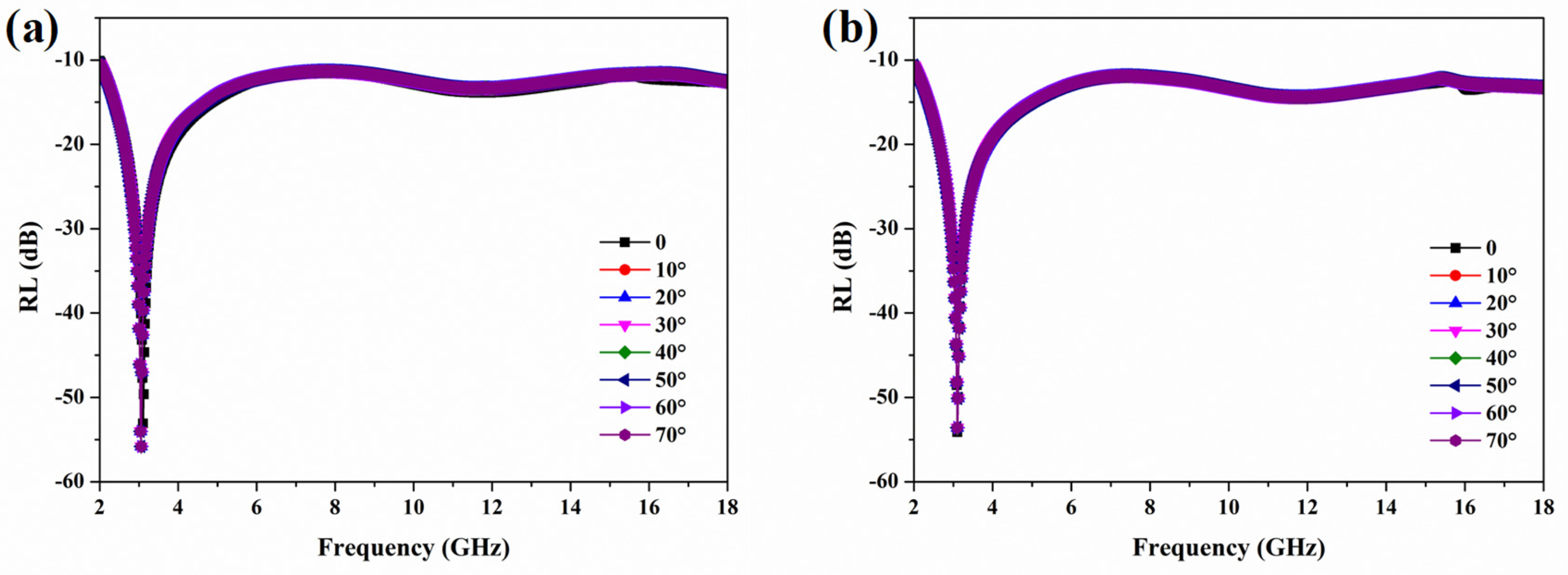
Considering the fabrication feasibility, we embedded a 0.25 mm-thick split-ring metasurface into the top panel according to Figure 1a. Figure 9 exhibits the RL of the split-ring metasurface-loaded honeycomb sandwich structure with different incidence angles in TE and TM modes. When the split-ring metasurface was introduced, the honeycomb sandwich structure exhibited insensitivity to the incidence angle and polarization direction of the microwave. The electric or magnetic field perpendicular to the split-ring metasurface under the oblique incidence of the microwave conferred on the metasurface left-handed material properties, and the corresponding RL was insensitive to incidence angle [21,22,23,24]. For different incidence angles and polarization directions of the microwave, the RL was less than −10 dB, indicating our proposed split-ring metasurface-loaded honeycomb sandwich structure can be used as an effective strategy to solve the stealth performance degradation of aircraft with large curvature. An RL of less than −10 dB means the microwave absorption efficiency was >90%, and the corresponding frequency band is defined as an effective absorption bandwidth (EAB), which is an important performance parameter for stealth aircraft. As is shown in Figure 9, through the optimization of low-frequency band microwave absorption efficiency, EAB covered the entire 2–18 GHz frequency band, which means the structure we proposed can effectively absorb microwave energy.

4. Conclusions

A split-ring metasurface-loaded honeycomb sandwich structure that is insensitive to the incidence angle and polarization direction of microwaves is proposed in this paper. Experimental and numerical results indicate that the split-ring metasurface plays a crucial role in improving microwave absorption efficiency and RL insensitivity to the incidence angle of microwaves. On one hand, the split-ring metasurface prepared with Ni-doped ZIF-67/ER generated a strong resonance loss in the 2–4 GHz frequency band while taking into account high-frequency impedance matching. On the other hand, the electric or magnetic field perpendicular to the split-ring metasurface under the oblique incidence of the microwave conferred on the metasurface left-handed material properties which make RL insensitive to the incidence angle. Therefore, the split-ring metasurface-loaded honeycomb sandwich structure can be used as an effective strategy to solve the stealth performance degradation of aircraft with large curvature.

Author Contributions

Data curation, Y.Z.; Formal analysis, R.M.; Funding acquisition, Z.X.; Investigation, Q.L., Y.Z. and Z.X.; Methodology, G.J.; Project administration, Q.L.; Resources, G.J.; Software, Y.Z.; Writing—original draft, Y.Z. and Q.L.; Writing—review & editing, R.M. All authors have read and agreed to the published version of the manuscript.

Funding

This research received no external funding.

Institutional Review Board Statement

Not applicable.

Informed Consent Statement

Not applicable.

Data Availability Statement

All the data are available within the manuscript.

Conflicts of Interest

The authors declare no conflict of interest.

References

  1. Zhao, Y.; Shan, Y.; Ji, G.; Sun, Y.; Shi, W.; Li, M. Enhanced Microwave-Absorbing Property of Honeycomb Sandwich Structure with a Significant Interface Effect. Materials 2022, 15, 5741. [Google Scholar] [CrossRef] [PubMed]
  2. Huang, Y.; Wu, D.; Chen, M.; Zhang, K.; Fang, D. Evolutionary Optimization Design of Honeycomb Metastructure with Effective Mechanical Resistance and Broadband Microwave Absorption. Carbon 2021, 177, 79–89. [Google Scholar] [CrossRef]
  3. Micheli, D.; Vricella, A.; Pastore, R.; Marchetti, M. Synthesis and Electromagnetic Characterization of Frequency Selective Radar Absorbing Materials Using Carbon Nanopowders. Carbon 2014, 77, 756–774. [Google Scholar] [CrossRef]
  4. Sheffield, R.G. Official F-19 Stealth Fighter Handbook; Compute: New York, NY, USA, 1989. [Google Scholar]
  5. Zhou, Q.; Xue, B.; Sg, A.; Gu, S.; Ye, F.; Fan, X. Ultra Broadband Electromagnetic Wave Absorbing and Scattering Properties of Flexible Sandwich Cylindrical Water-based Metamaterials. Res. Phys. 2022, 38, 105587. [Google Scholar] [CrossRef]
  6. Zainud-Deen, S.H.; Malhat, H.A.; Shabayek, N.A. Reconfigurable RCS Reduction from Curved Structures Using Plasma Based FSS. Plasmonics 2020, 15, 341–350. [Google Scholar] [CrossRef]
  7. Yin, X.; Kong, L.; Zhang, L.; Cheng, L. Electromagnetic Properties of Si-C-N Based Ceramics and Composites. Int. Mater. 2014, 59, 326–355. [Google Scholar] [CrossRef]
  8. Chen, X.; Wu, Y.; Gu, W.; Zhou, M.; Tang, S. Research Progress on Nanostructure Design and Composition Regulation of Carbon Spheres for the Microwave Absorption. Carbon 2022, 189, 617–633. [Google Scholar] [CrossRef]
  9. Liu, Q.; Zeng, M.; Liu, J. Fe-based Material@N-doped Carbon Composites as Environment-Friendly Microwave Absorbers. Carbon 2021, 171, 646–657. [Google Scholar] [CrossRef]
  10. Zhang, B.; Mahariq, B.; Tran, N. Enhanced Electromagnetic Wave Dissipation Features of Magnetic Ni Microspheres by Developing Core-Double Shells Structure. Ceram. Int. 2022, 48, 446–454. [Google Scholar] [CrossRef]
  11. Min, Y.L.; Choi, Y.L.; Woo, H.J.; Sang, W.K. Microwave Absorption Properties of Ni0.6Zn0.4Fe2O4 Composites with Nonmagnetic Nanoferrite Percentages. Ceram. Int. 2022, 48, 20187–20193. [Google Scholar]
  12. Zeng, M.; Cao, Q.; Liu, J.; Guo, B.; Hao, X.; Liu, Q. Hierarchical Cobalt Selenides as Highly Efficient Microwave Absorbers with Tunable Frequency Response. ACS Appl. Mater. Interfaces 2020, 12, 1222–1231. [Google Scholar] [CrossRef]
  13. Zhao, Y.; Wang, Q.; Sun, Y. A Frequency Selective Surface Loaded Two-Layer Composite for Tunable Microwave Absorption. Mater. Res. Express 2022, 9, 066301. [Google Scholar] [CrossRef]
  14. Yadav, R.; Panwar, R. Effective Medium Approximation Fused Optimization Strategy Derived New Kind of Honeycomb Microwave Absorbing Structure. IEEE Trans. Magn. 2022, 58, 2501311. [Google Scholar] [CrossRef]
  15. Baek, S.M.; Lee, W.J.; Kim, S.Y.; Kim, S.S. A Study on the Microwave Absorbing Honeycomb Core Embedded with Conductive Periodic Patterned Surfaces for the Effective Dielectric Constant. Compos. Struct. 2022, 289, 115471. [Google Scholar] [CrossRef]
  16. Pang, H.; Duan, Y.; Dai, Y. The Electromagnetic Response of Composition-Regulated Honeycomb Structural Materials used for Broadband Microwave Absorption. J. Mater. Sci. Technol. 2021, 88, 203–214. [Google Scholar] [CrossRef]
  17. He, F.; Si, K.; Zha, D.; Li, R.; Jiang, J. Broadband Microwave Absorption Properties of a Frequency-Selective Surface Embedded in a Patterned Honeycomb Absorber. IEEE Trans. Electromagn. Compat. 2021, 63, 1290–1294. [Google Scholar] [CrossRef]
  18. Liu, Y.; Yang, J.; Xu, J. Electromagnetic and Microwave Absorption Properties of Ti3SiC2/AgNWs/ Acrylic Acid Resin Composite Coatings with FSS Incorporation. J. Alloys Compd. 2022, 899, 163327. [Google Scholar] [CrossRef]
  19. Miles, P.A.; Westphal, W.B.; Von Hippel, A. Dielectric Spectroscopy of Ferromagnetic Semiconductors. Rev. Mod. Phys. 1957, 29, 279–307. [Google Scholar] [CrossRef]
  20. Naito, Y.; Suetake, K. Application of Ferrite to Electromagnetic Wave Absorber and its Characteristics. IEEE Trans. Microw. Theory Tech. 1971, 19, 65–71. [Google Scholar] [CrossRef]
  21. Smith, D.R.; Schultz, S.; Markos, P. Determination of Effective Permittivity and Permeability of Metamaterials from Reflection and Transmission Coefficients. Phys. Rev. B 2001, 65, 195104. [Google Scholar] [CrossRef] [Green Version]
  22. Koschny, T.; Markos, P.; Smith, D.R. Resonant and Antiresonant Frequency Dependence of the Effective Parameters of Metamaterials. Phys. Rev. E 2003, 68, 065602. [Google Scholar] [CrossRef] [PubMed]
  23. Linden, S.; Enkrich, C.; Wegener, M. Magnetic Response of Metamaterials at 100 Terahertz. Science 2004, 306, 1351–1353. [Google Scholar] [CrossRef] [PubMed] [Green Version]
  24. Katsarakis, N.; Koschny, T.; Kafesaki, M.; Economou, N.E. Electric Coupling to the Magnetic Resonance of Split Ring Resonators. Appl. Phys. Lett. 2004, 84, 2943–2945. [Google Scholar] [CrossRef]
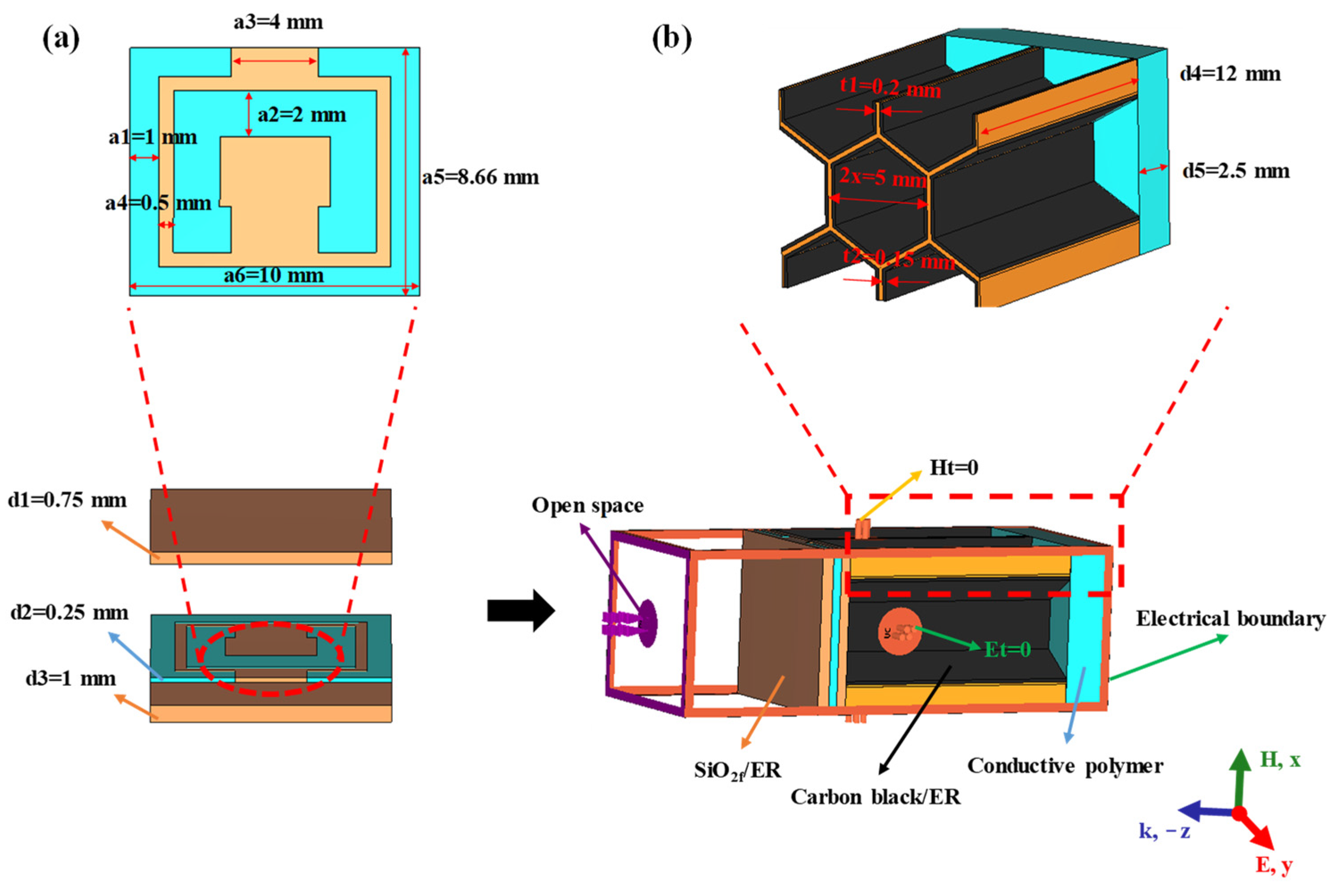
Figure 1. Schematic of a unit cell in the designed honeycomb sandwich structure: (a) FSS-loaded top panel layer, (b) honeycomb and bottom panel layer.
Coatings 12 01706 g001
Figure 2. The schematic illustration of arch method.
Coatings 12 01706 g002
Figure 3. Relative complex permittivity (a) and corresponding RL with different thickness (b) and tanδ (c) of honeycomb core.
Coatings 12 01706 g003
Figure 4. Real (a) and imaginary (b) parts of impedance at different honeycomb thicknesses.
Coatings 12 01706 g004
Figure 5. Electromagnetic parameters of Ni-doped ZIF-67/ER: (a,b) relative complex permittivity and permeability, (c,d) real and imaginary part of impedance, (e,f) dielectric and magnetic loss tangent.
Coatings 12 01706 g005aCoatings 12 01706 g005b
Figure 6. Real (a) and imaginary (b) parts of impedance, impedance matching performance (c) as well as RL (d) of honeycomb with different bottom panel layer thicknesses.
Coatings 12 01706 g006
Figure 7. RL of split-ring metasurface at different thicknesses in TE (a) and TM (b) modes.
Coatings 12 01706 g007
Figure 8. Simulated distributions of power loss density of split-ring metasurface in TE mode (a,b) and TM mode (c,d) at 3 GHz and 14 GHz frequency points, respectively.
Coatings 12 01706 g008
Figure 9. RL of split-ring metasurface--loaded honeycomb sandwich structure with different incidence angles in TE (a) and TM (b) modes.
Coatings 12 01706 g009
Table 1. List of frequency testing ranges and dimensions of samples.
Frequency Ranges (GHz)Dimensions of Samples (mm)
1.72–2.6154.46 × 108.92 × (8.0–12.0)
2.60–3.9533.89 × 71.84 × (8.0–12.0)
3.94–5.9922.0 × 47.25 × (8.0–12.0)
5.38–8.215.75 × 34.70 × (2.0–6.0)
8.2–12.422.9 × 10.2 × (2.0–6.0)
12.4–1815.9 × 8.03 × (2.0–4.0)
Publisher’s Note: MDPI stays neutral with regard to jurisdictional claims in published maps and institutional affiliations.