Article

The Array of Si Nanowires Covered with Ag Nanoparticles by ALD: Fabrication Process and Optical Properties

1
Ioffe Institute, 194021 St. Petersburg, Russia
2
Peter the Great Saint-Petersburg Polytechnic University, 195221 St. Petersburg, Russia
3
ITMO University, 197101 St. Petersburg, Russia
4
Saint Petersburg State University, 199034 St. Petersburg, Russia
5
Institute of Chemical Technology, 16628 Prague, Czech Republic
*
Author to whom correspondence should be addressed.
Coatings 2022, 12(11), 1748; https://doi.org/10.3390/coatings12111748
Submission received: 24 October 2022 / Revised: 8 November 2022 / Accepted: 10 November 2022 / Published: 15 November 2022
(This article belongs to the Special Issue Atomic Layer Deposition of Oxide Thin Films)

Abstract

:
In this work, we proposed a method for creating an Ag/Si composite structure consisting of an array of vertical silicon nanowires (SiNWs) decorated with silver nanoparticles (AgNPs). A two-stage metal-assisted chemical etching of Si was used to obtain the SiNW array, and atomic layer deposition was used to fabricate the AgNPs. A uniform distribution of AgNPs along the SiNW height was achieved. The measured characteristics by spectroscopic ellipsometry directly established the presence of AgNPs deposited on the SiNWs. The height of the sublayers and the fractions of Si and Ag in them were determined using the multilayer model and the effective Bruggeman medium approximation in the interpretation of the experimental data. For AgNP layers deposited on an Si wafer surface, the thickness (from 2.3 to 7.8 nm) and complex dielectric functions were verified within the framework of the Drude–Lorentz model. The optical properties of Ag/SiNW structures with complex spatial geometry were simulated in the COMSOL Multiphysics software. The expected localization of the electric field on the surface and near the AgNP was observed as a result of the plasmon resonance excitation. The calculated enhancement factor reached 1010, which indicates the possibility of using such structures as substrates for surface-enhanced Raman scattering.

Graphical Abstract

1. Introduction

When incident light (photons) interacts with electrons in metal nanoparticles (NPs), localized plasmon resonance is excited [1]. Its parameters (energy, amplitude, and damping factor) are affected by the shape of NPs, the distance between them, and their size, as well as the optical properties of the substrate and the environment, by varying which the plasmon characteristics can be controlled. As a rule, metal NPs are deposited on flat substrates made of dielectrics or semiconductors, and air serves as the environment. Among semiconductors, of particular interest are silicon substrates, which are widely used in nanoelectronics [2] and optoelectronics [3]. Semiconductor technology is well developed for fabricating structures of various topologies and morphologies; therefore, Si-based plasmonic structures are attractive from the point of view of their implementation for mass production. Nowadays, Si structures can be obtained with a highly developed surface in the form of porous silicon [4], the form of silicon vertical walls [5] or arrays of vertical silicon nanowires (SiNWs) [6]. Such high-aspect Si structures are fabricated by anisotropic [5], electrochemical [4,7] or metal-assisted chemical [8] etching of a single-crystal c-Si substrate. As a result of etching, it is possible to obtain Si grooves, pores in Si or an array of SiNWs on a substrate. The method of metal-assisted chemical etching (MACE) of Si, which we have chosen, consists of two stages. Firstly, nanoparticles (or film) of a noble metal are deposited onto the surface of a monocrystalline silicon substrate. Then, the silicon substrate is placed in an electrolyte solution consisting of an etchant (HF) and an oxidizing agent (H2O2, HNO3, etc.), where etching and formation of silicon nanostructures take place. It is important to note the features of the SiNW structure: the filament material retains the crystallographic orientation of the initial c-Si substrate, while the total surface area of the structure per unit volume increases significantly due to the lateral surface of the SiNWs. Composite structures based on SiNWs are promising for application due to their decoration with metal particles of noble metals [9,10,11]. There are different ways to obtain such composite structures, for example, chemical deposition of metal nanoparticles from solutions [12,13,14] and sputtering [15,16].
Traditionally, resistive, electron, and magnetron methods are used to deposit NP layers, but due to the ballistic trajectory of the sputtered precursor, it is a difficult task to ensure uniform deposition of nanoparticles in porous structures or on vertical nanofilaments. For example, the use of the chemical vapor deposition (CVD) technology for the deposition of AgNPs on silicon tips does not lead to uniform deposition [17]. In Refs. [18,19], the deposition of gold nanoparticles in porous silicon with a high surface area to volume ratio was carried out using chemical deposition from an Au-containing solution. The slow rate of diffusion of the solution of gold ions into the pores leads to their deposition at the tips of the pores. A suitable method for the uniform deposition of nanoparticles on such arrays is atomic layer deposition (ALD) [20], which can be used to control the deposition thickness with great accuracy, and without any special requirements for the surface topology compared to the CVD method. The ALD method is a chemical technology for producing thin coatings and films, which is based on cyclic and self-limiting reactions at the gas–solid interface. During the ALD method, pairs of reagents are successively chemisorbed on the substrate surface. The cyclical nature of the ALD processes enables precise control of coating thicknesses down to sub-nanometers. Moreover, such self-limiting surface reactions at the substrate–gas interface provide layer-by-layer growth of films and make it possible to conformally deposit thin films on complex three-dimensional and porous substrates. At present, the ALD method is widely used in the fields of microelectronics, nanotechnology, catalysis, energy, etc. [21,22,23,24,25,26]. Thus, the growth of interest in the ALD method in the industry and a dramatic increase in the publications over the last decade have been achieved due to these functions and good scalability [27].
The use of suitable precursors is critical in ALD processes. So, a review of currently available precursors was carried out to obtain AgNPs and nanolayers by the ALD method (Table 1) [28,29,30,31,32,33,34,35,36,37,38,39,40,41,42,43]. However, they all have significant drawbacks. On the one hand, due to the high molecular weight and intermolecular interactions, they have a low saturated steam pressure. In this regard, these reagents must be heated to relatively high temperatures, which can lead to the formation of particles not on the surface (ALD) but in the gas phase (CVD). On the other hand, these reagents are unstable at high temperatures, which often leads to uncontrolled growth due to parasitic CVD-like processes. Most silver-containing ALD precursors are non-volatile substances that are unstable at standard ALD temperatures (150–200 °C). Among them, the most suitable precursor for ALD processes is 2,2-dimethyl-6,6,7,7,8,8,8-heptafluorooctane-3,5-dionato) silver (I) triethyl-phosphine (Ag (fod) (PEt3), C16H25AgF7O2P) (98%, Strem Chemicals, Newburyport, MA, USA) due to its thermal stability and hydrogen plasma as a reducing agent [32,33,34,35,36,37,38,39,40].

2. Materials and Methods

2.1. Fabrication of SiNWs

To create an array of silicon nanowires, we used p-type silicon with a resistivity of 10 Ohm∙cm and crystallographic orientation (100). The silicon wafers were subjected to Radio Corporation of America (RCA, New York, USA) cleaning (New York, USA). As mentioned earlier, the method (MACE) of Si was used to obtain an array of silicon nanowires [8]. The technique we chose consisted of two stages [44]. Firstly, AgNPs were deposited onto the surface of the c-Si substrate from a solution of 0.02 M AgNO3 + 5 M HF (1:1) for 30 s (Figure 1, steps 1–2). Then, the silicon substrate was placed in the electrolyte solution 5 M HF + H2O2 (10:1), where etching and formation of silicon nanowires took place for 10 and 20 s to obtain structures of different heights (Figure 1, step 3), with sample names S1 and S2, respectively. After the removal of silver, which was a catalyst for the creation of SiNWs in the MACE process, and the washing of SiNWs from the reaction products (Figure 1, step 4), the atomic layer deposition process was carried out to decorate silicon nanowires with AgNPs to create a composite structure (Figure 1, step 5).

2.2. Precipitation of AgNPs by ALD Method

ALD is a chemical technology for producing thin films and coatings based on cyclic and self-limiting reactions at the gas–solid interface. In the ALD process, sequential chemisorption of reactant vapors on the substrate surface occurs. The cyclical nature of the ALD processes ensures precise thickness control down to sub-nanometers. In addition, self-limiting surface reactions at the substrate–gas phase interface provide layer-by-layer growth of films and allow conformal deposition of thin films on complex three-dimensional and porous substrates.
AgNPs were deposited by the ALD method on a Picosun R-150 setup using the Ag (fod) (PEt3) precursor and hydrogen plasma as a reducing agent, as described in Ref. [45]. To determine the optimal growth condition, the reactor temperatures (142–184 °C), (Ag (fod) (PEt3)) container temperatures (115–150 °C), reagents pulse times (2–4 s) and number of pulses (1–11) in one ALD cycle were varied.
The development of ALD regimes and the characterization of the resulting Ag layers were first carried out on a Si wafer surface.

2.3. Scanning Electron Microscopy (SEM)

The JSM-7001F Scanning Electron Microscope (SEM) (JEOL, Tokyo, Japan) was used to study the morphology of nanostructures in the secondary electron mode and using an accelerating voltage of 5 keV. A statistical analysis of nanostructures was carried out (average size, coverage factor) according to SEM images and using open-source ImageJ software.

2.4. X-ray Photoelectron Spectroscopy (XPS)

Chemical composition of the sample surface was studied by X-ray photoelectron spectroscopy (XPS). XPS spectra were measured with a Escalab 250Xi (Thermo Fisher Scientific Inc, Waltham, MA, USA). The samples were excited by Al Kα (1486.7 eV) X-rays for measurements. An ion gun was used to spray the surface.

2.5. Spectroscopic Ellipsometry

The ellipsometric characteristics were studied using a SE2000 spectral ellipsometer (Semilab, Budapest, Hungary) in the wavelength range λ from 400 to 1700 nm at an angle of incidence of φ = 70°. The optical lenses of the ellipsometer were used for micro-focusing of the probing spot size (400 μm) in order to reduce the effect of inhomogeneities on the surface of the SiNW array. The advantage of ellipsometry over spectrophotometry is that two parameters are simultaneously measured: ellipsometric angles ψ and Δ, where ψ = |rp|/|rs| is the ratio of the reflection coefficients, and Δ = δrpδrs is the relative phase difference between the p- and s-components, experienced in reflection.
Since ellipsometry [46] is not a direct method for determining dielectric functions, the choice of a model is required, for example, in the form of a thin layer with some thickness and its complex dielectric function ε. Next, the complex reflection coefficients rp and rs for p- and s-polarizations were calculated using the Fresnel formulas, and then using the main ellipsometry Equation (1):
Ρ = rp/rs = tan(ψ)exp()
Ellipsometric angles ψcalc and Δcalc were calculated. By varying the model parameters in the indicated wavelength range, ψcalc and calc were found in such a way that, when compared with the experimental data, the best fit was obtained using regression analysis. The above model parameters were set as a result of the search. A similar search procedure was used to determine the thickness and complex dielectric function of AgNPs layers on a Si substrate using the Drude-Lorentz model [47]. The Ag/SiNWs composite structures were interpreted using the Bruggeman’s effective medium approximation model (B-EMA) [48] from the software package supplied with the ellipsometer.

2.6. Simulation of Electromagnetic Field Enhancement in a Composite Structure

The simulation of the electromagnetic field propagation was carried out using the COMSOL Multiphysics software, which applied the 3D Finite Element Method (FEM) and the Maxwell equation with the calculation of the field propagation in the model. We used the Electromagnetic Waves module and Frequency Domain in the calculation.

3. Results and Discussions

3.1. Fabrication Conditions of the AgNP Layers on the Si Wafer Surface Using ALD

The selection of optimal conditions is the most important criterion in the preparation of coatings by the ALD method; this ensures the achievement of a sufficient amount of reagents to saturate the reactor and self-limiting reactions. By changing the duration of the reagents’ inlet (pulse duration) and the temperature of the evaporator of the reagents, the required amount of reagents was achieved. The higher the evaporator temperature, the higher the reagent vapor pressure and the more reagents that arrive at the substrate surface.
Therefore, at the first stage of the search for optimal conditions for the ALD method, the influence of the Ag (fod) (PEt3) evaporator temperature was studied. The film thickness reached at least 2 nm at an evaporator temperature of 140 °C and 700 ALD cycles. With a further increase in temperature, the growth rate decreased. This is due to the thermolysis of the Ag (fod) (PEt3) precursor, which becomes unstable at high temperatures [38]. Thus, the temperature should be in the range of 120–160 °C for the optimal ALD growth of Ag using a precursor [32]. Therefore, the reagent cannot be heated above 150 °C.
As for the optimal temperature range of the reactor, it should be 155–165 °C, at which the growth rate is maximum and relatively constant. The resulting ALD window for our set-up coincides with the upper threshold of the ALD window for similar processes described in Ref. [31].
Thus, the optimal conditions for the synthesis of AgNPs by ALD for our equipment are the reactor temperature of 165 °C and the evaporator temperature of 140–150 °C.
Varying the temperature parameters, the regimes of the obtained AgNPs layers were established, the thickness of which were sufficient for an ellipsometric study.
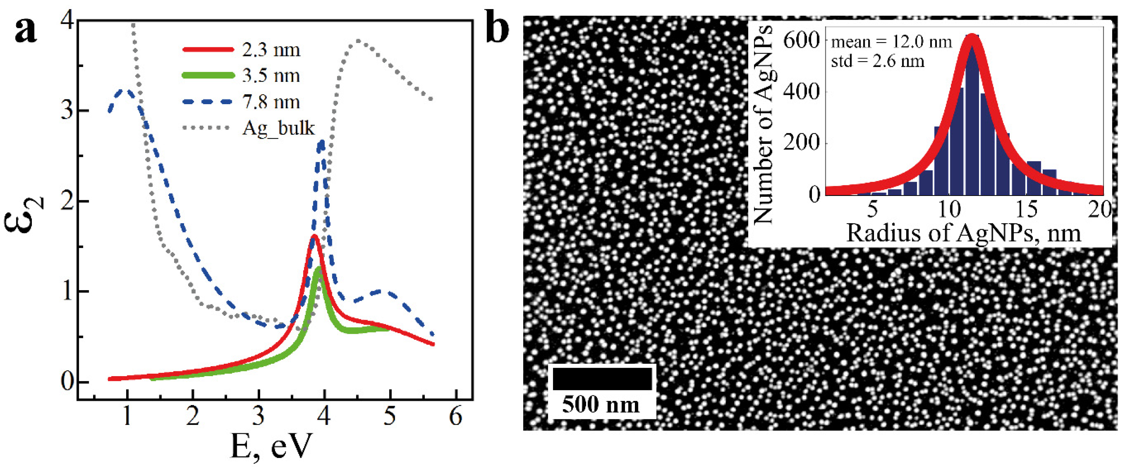
Good agreement was obtained between calculation and experiment for three samples of AgNP layers with determination of their thicknesses, dAg = 2.3, 3.5, and 7.8 nm, as well as optical characteristics in the form of complex dielectric functions (real ε1 and imaginary ε2 parts) in a wide spectral range by measuring the ellipsometric angles ψexp и exp and using the Drude–Lorentz model. Since ε2 gives more information about the supposed resonances in the structures of the AgNP layers, Figure 2a shows only the dependences of ε2 on photon energy (E). All AgNP structures obtained by ALD on a Si substrate exhibit a narrow peak of the bulk plasmon resonance in the longitudinal mode at E = 3.9 eV [49,50], while the sample with dAg = 7.8 ± 0.3 nm has an additional peak with a maximum localized plasmon resonance at E = 0.95 eV (λ = 1305 nm). This layer of AgNPs was obtained for 2300 cycles of ALD (Figure 2b), the SEM image of which was analyzed in the ImageJ software and the average NPs diameter dAg = 24 ± 5.6 nm was determined at an Ag fill factor of 18%. For this sample, the spectrum of the imaginary part of the permittivity in the visible region has dependence close to the function ε2 of bulk Ag [51].

3.2. Study of the Chemical Composition of the AgNPs Layer Using XPS

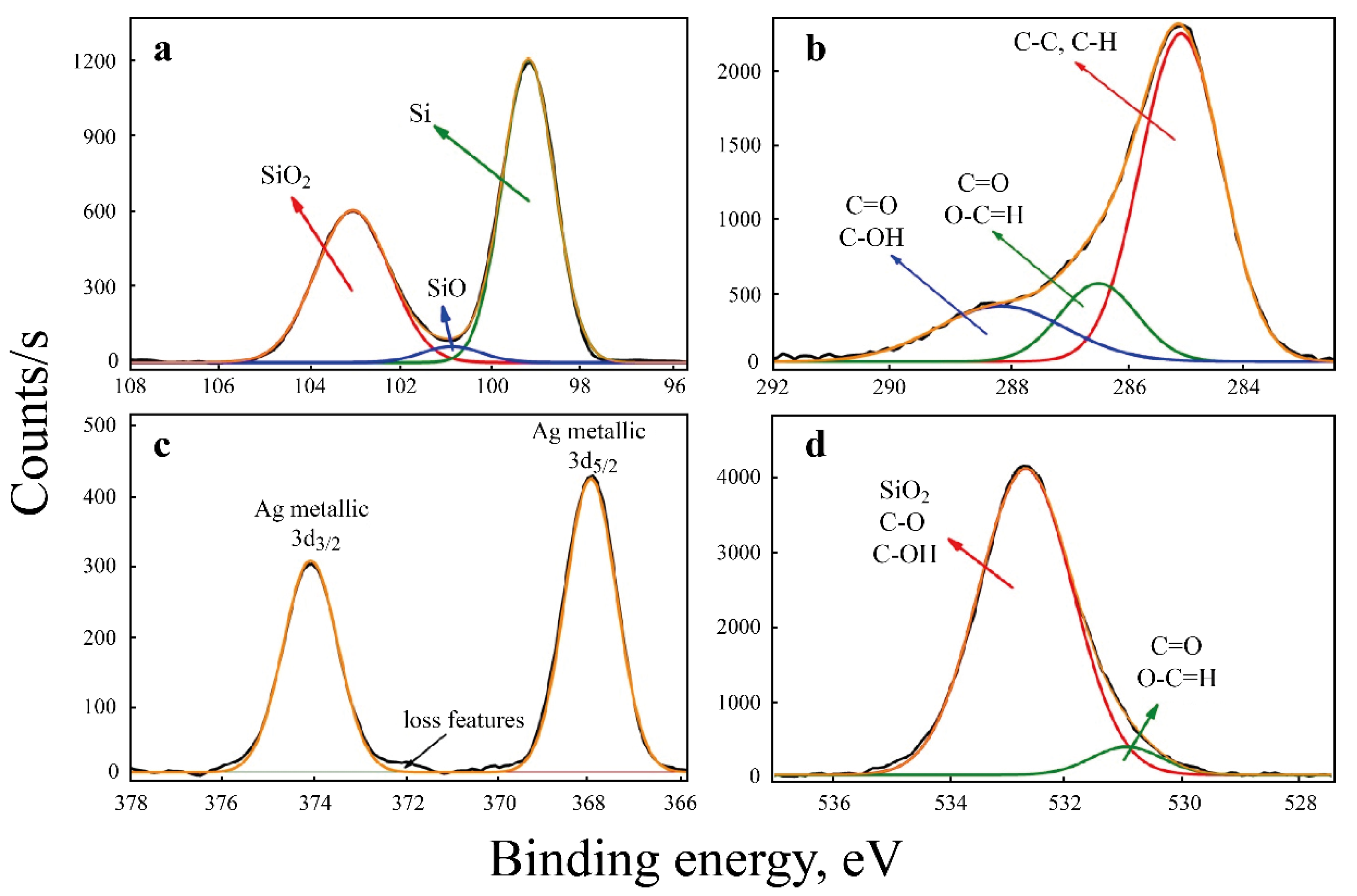
The chemical composition of the AgNP layer on the c-Si substrate was studied by XPS. Only silver, oxygen, carbon and silicon were found on the surface (Figure 3). Fluorine and phosphorus contained in the original silver-containing reagent were not detected. The presence of silicon confirms that the silver does not completely cover the surface, which is consistent with the SEM image (Figure 2b) where the AgNPs are indeed isolated without forming a continuous silver film. The thickness of the oxide film on silicon is very small (several nanometers), since the Si2p spectrum clearly shows a peak at 99.3 eV, which is characteristic of silicon in the zero oxidation state (Figure 3a). The presence of carbon (Figure 3b) is due to surface contamination with adsorbed organic compounds in the air. Silver is in the metallic form according to the analysis of the spectrum of the Ag3d level (Figure 3c). The presence of oxygen (Figure 3d) is also due to organic pollution and the presence of an oxide film on the silicon surface.

3.3. Morphology of SiNWs

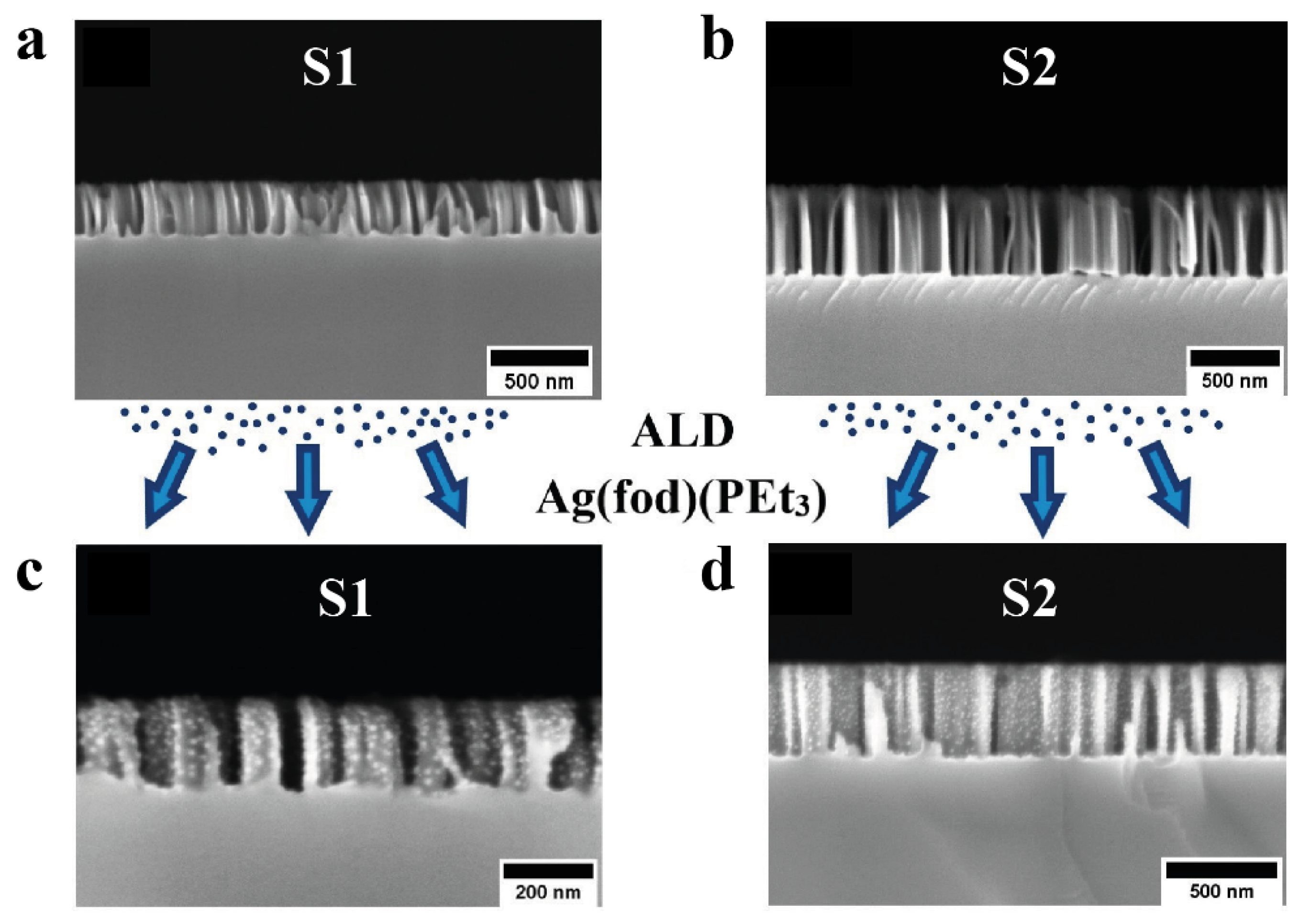
With the help of MACE, detailed in Section 2.1, the structures presented in Figure 2 were obtained. The cross-section SEM images show the sample S1 (Figure 4a) with filament height hSiNWs = 234 nm and the sample S2 (Figure 4b) with hSiNWs = 469 nm.
One can note their even etching front over the entire area of the structure, as well as the even upper limit of the nanowire height, which is obtained by the SiNW fabrication method; in addition, this relatively even interface between the array and the external environment (air) allows one to carry out ellipsometric measurements that are not complicated by strong irregularities of the studied material.

3.4. Study of AgNPs Deposited on SiNWs

Both initial samples of SiNWs (S1 and S2) were placed in the same chamber during AgNP deposition, as well as with flat samples to control the thickness of resulting ALD layers. This provided fixed conditions for the deposition of AgNPs on SiNWs of various morphologies. The cross-section SEM images for these two samples of Ag/SiNWs are shown above in Figure 4c,d. The open-source ImageJ software was used to statistically analyze Ag/SiNW and Ag/Si composite structures, and the average diameter of silver nanoparticles deposited on SiNWs using the ALD method was 12 ± 2 nm, which turned out to be almost two times smaller than the particle diameter Ag deposited on the Si wafer surface (24 ± 5.2 nm). It is assumed that the supply of gaseous ALD reagents to the surface of SiNWs is somewhat limited due to the “forest” of NWs, while in the case of a planar substrate, the reagents freely reach it, forming NPs with an increased diameter.

3.5. Ellipsometric Study of SiNW Arrays before and after the Deposition of AgNPs

Figure 5a,b for the initial SiNW structure (sample S1) show the spectra of the measured ellipsometric angles ψ (λ) and Δ (λ) (black symbols and lines), respectively.
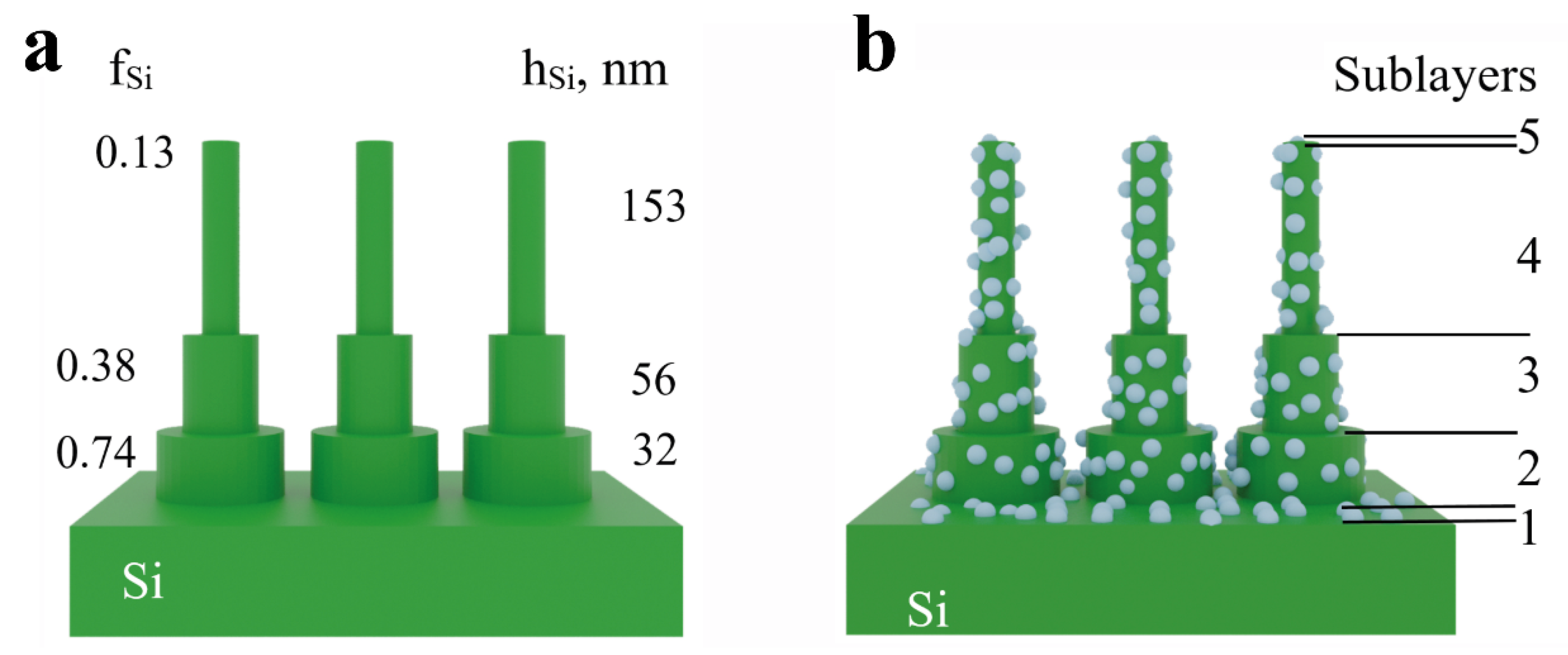
To interpret the ellipsometric data of SiNW samples, a model was chosen in which the three-dimensional structure of vertical wires located on the substrate (Figure 6a) was divided into several conditional sublayers, with boundaries parallel to the substrate [6,7,44]. Thus, it is possible to model each of the sublayers with the appropriate parameters of the height, and an array can be considered as a composite consisting of Si and air. In our case, a three-layer model was used, in which the height of each of the three sublayers and Si fraction (hSi and fSi) were fitted, so the total number of unknown parameters was six. The value of the Si fraction fSi and the fraction of voids fvoids = (1 − fSi) dependent on it were determined in the framework of the Bruggeman’s effective medium approximation. The optical constants of single-crystal silicon were taken from the handbook [52].
Experimental and calculated ellipsometric angles (ψ and Δ) for this model, after fitting, are shown in Figure 5a,b (black symbols and lines, respectively). As a result, fSi and hSi were determined for each of the three sublayers, which are shown in Figure 6a. When summing hSi of all three sublayers, the total height is hSi = 241 nm, which is close to the height of 234 nm obtained from the SEM image in Figure 4a.
To interpret the ellipsometric data for an array of SiNWs with AgNPs, the same model was used as for SiNWs, but with the addition of an AgNP layer that was deposited on the surface of the nanowires, as shown in Figure 6b. According to this model, the AgNP layer fills a certain volume fAg, which somewhat reduces the void fraction (fvoids), while the Si (fSi) fraction should remain unchanged. The spread in the AgNP diameters deposited on SiNWs is insignificant (± 2 nm), obtained from the analysis of SEM images (cross-section) of Ag/SiNW samples in the ImageJ software. Taking into account that the additional new parameter fAg in all three sublayers is approximately the same, its value was used in the search in the Bruggeman model to calculate the dielectric function of the effective medium. In addition, it is assumed that AgNPs are deposited at the top of each wire (fAg on sublayer 5) as well as at the bottom (on the substrate) between the wires (fAg on sublayer 1). As a result of fitting these parameters in Figure 5a,b, the convergence of the experimental and calculated spectra for the S1 sample with AgNPs ψ (λ) and Δ (λ) (red), respectively, was obtained, as shown in Figure 6a,b. It was found that for the first sublayer fAg = 0.19, for sublayers 2, 3 and 4, fAg = 0.06, 0.04 and 0.04, respectively, and for the fifth sublayer fAg = 0.05.
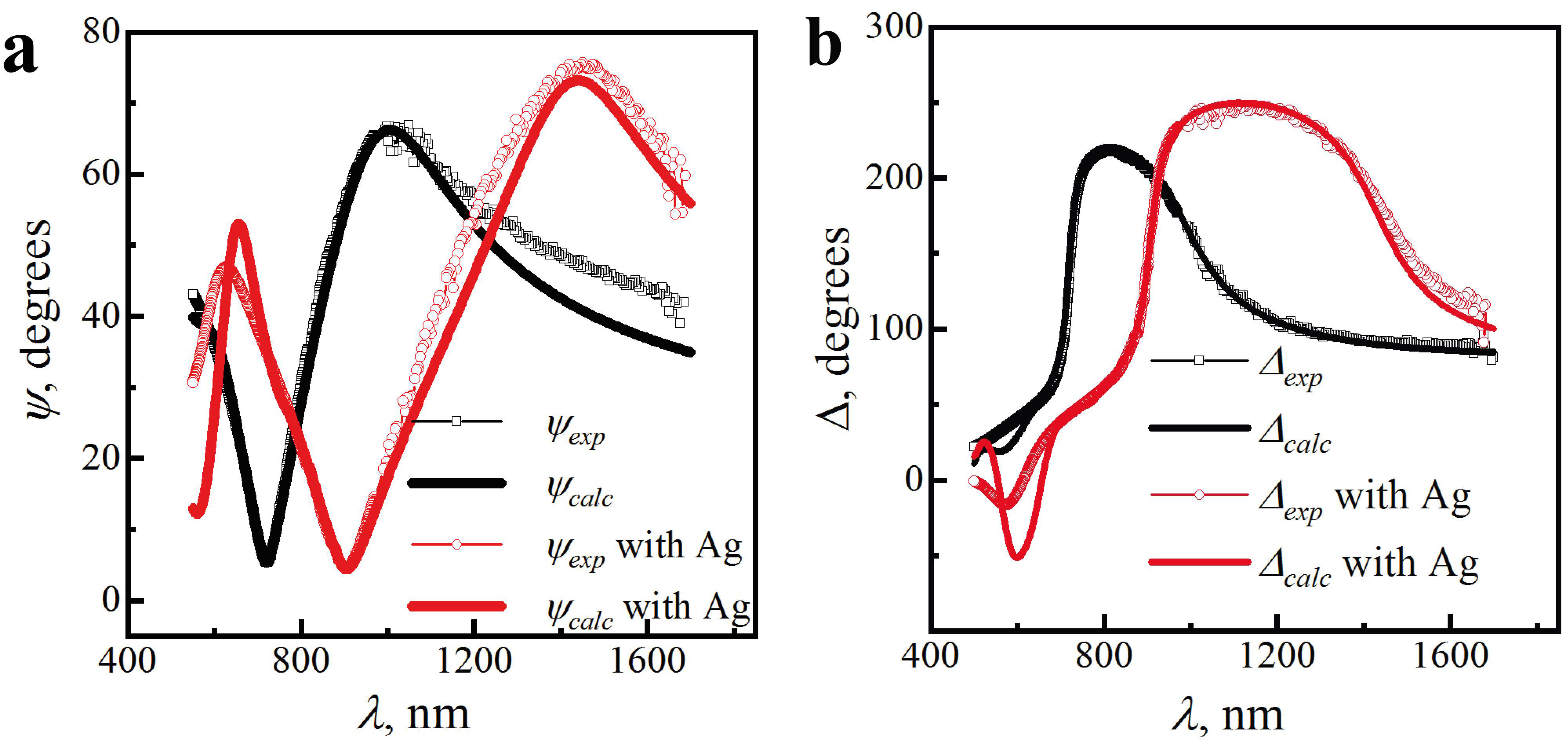
A similar approach in interpreting the ellipsometry data was used for another sample S2 with a SiNW height approximately two times higher (h = 469 nm from SEM image (Figure 4b)) than that of the previous sample. For this sample, Figure 7 shows the measured spectra of the ellipsometric angles ψexp and Δexp, as well as the calculated spectra ψcalc and Δcalc before (black) and after (red) the deposition of AgNPs.
The total height of each layer in the original SiNW structure was estimated as hSiNWs = 471 nm. This value is close to the value obtained from the cross-section SEM images of this sample from Figure 4b with the SiNW height of 469 nm. As in the previous example, a fraction of Ag is added to each wall of the SiNWs in the B-EMA model, assuming some Ag in the sublayers, including the upper and lower sublayers. Fitting the calculated ellipsometric angles (ψcalc and Δcalc) for this model, the convergence to the experiment was obtained, as can be seen in Figure 7. It was found that for the first sublayer fAg = 0.23, for sublayers 2, 3 and 4, fAg = 0.06, 0.05 and 0.05 and for the fifth sublayer fAg = 0.20.
For two SiNWs samples, after the deposition of AgNPs, a shift of the experimental spectra ψ (λ) to the long wavelength region was observed, which can be considered a qualitative confirmation of the appearance of an additional component in the structure, and the interpretation of this effect using a multilayer model and approximation of the Bruggeman’s effective medium made it possible to obtain optical data indicating the presence of AgNPs in the Ag/SiNW composite structure for all the sublayers. SEM and non-destructive spectroscopic ellipsometry are complementary methods for studying arrays of complex high-aspect composite structures.

3.6. Modeling the Propagation of an Electromagnetic Field in a Composite Nanostructure Using COMSOL Multiphysics

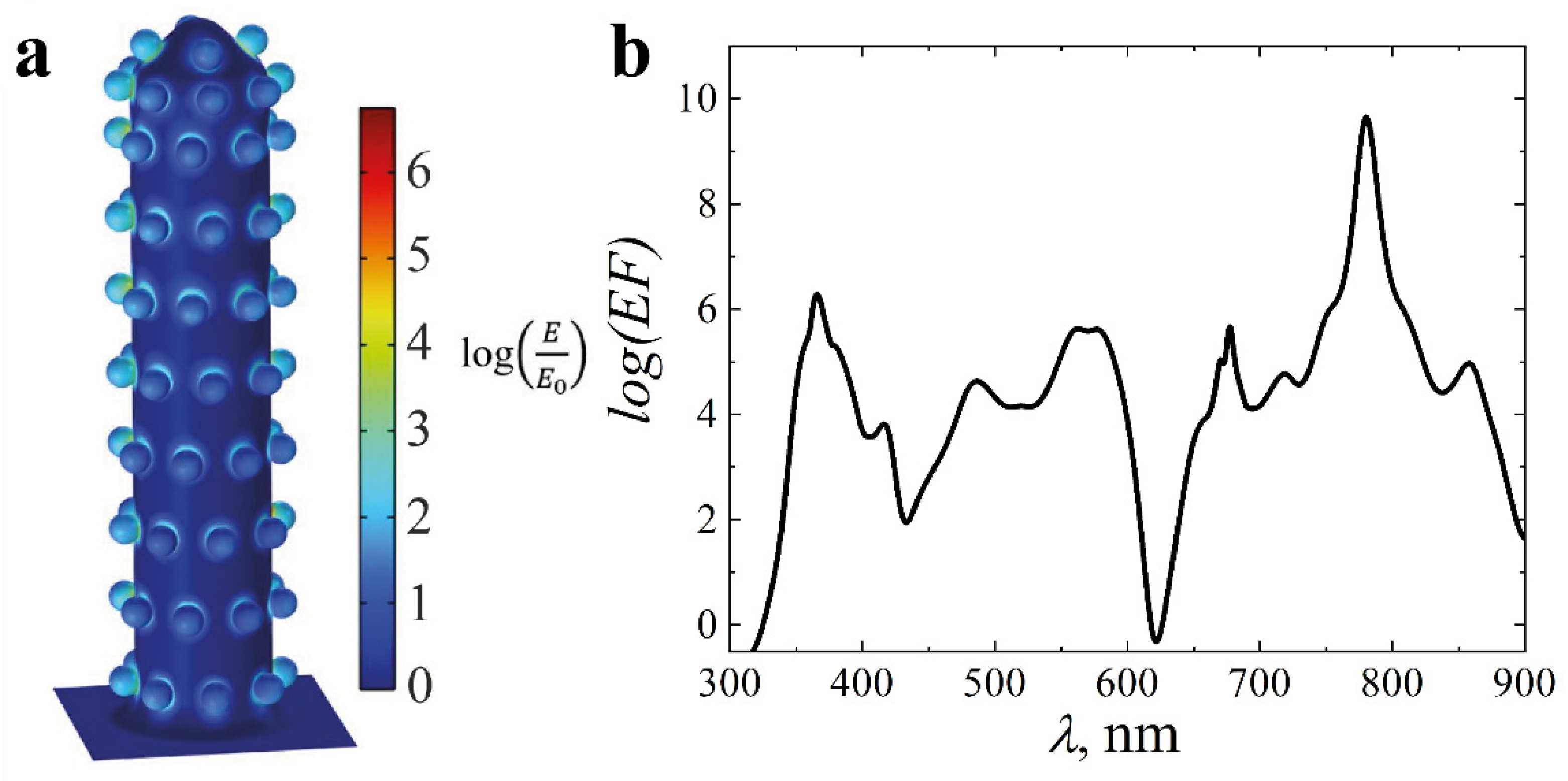
The model consisted of an Si substrate on which a cylindrical silicon nanowire with spherical nanoparticles on the surface was placed (Figure 8a). A periodic boundary condition was set on the side faces of the model. The light source was situated on the top face of the model. An ideally matched layer was located under the substrate, which absorbs the radiation falling into it, which makes it possible to reduce the thickness of the simulated substrate. The geometrical parameters (the length of the nanowire: 250 nm; the diameter: 50 nm; the diameter of the nanoparticle: 12 nm; with a distance between particles of 20 nm) were estimated from the SEM image of the experimental sample. As a result, the distribution of the electromagnetic field amplification (E is the intensity of the electromagnetic field, E0 is the intensity of the incident electromagnetic field) on the structure under study was obtained. The expected localization of the field on the surface and near the particle as a result of the excitation of plasmon resonance was observed.
In order to qualitatively assess the field enhancement that occurs in the structure, the enhancement factor (EF) was calculated according to Equation (2), where A is the surface area, E is the electric field vector of the model, and E0 is the electric vector of the incident field:
E F = 1 A E E 0 4
As a result, the maximum values of EF = 2 × 10⁶ at λ = 366 nm and 4.9 × 10¹⁰ at λ = 780 nm were obtained for the structure (Figure 8b).
For a one-dimensional layer of AgNPs, the enhancement factor reaches 104 [53]. In a layer of nanoparticles with a distance between them less than the particle radius, gap plasmon is excited, and the amplification reaches 1010; however, it should be noted here that such structures are difficult to fabricate due to the use of electron beam lithography [54].
The calculated Raman enhancement factor of the structure under study in this work reaches 1010; this value is sufficient to detect a low concentration of a substance or one molecule [54], which suggests the possibility of using the resulting metasurface as a highly sensitive SERS-active substrate, which is produced without the use of electron beam lithography.
If the question of practical application is raised, as noted in Ref. [54], with an enhancement of 107–108, it is possible to achieve detection of a single molecule of a substance using Raman scattering. In the resulting structure, the calculated factor reaches a higher value, which means that such a structure is promising as a substrate for enhancing Raman scattering, and it should be noted that lithography is not used in the technological process, which greatly simplifies the process.
Thus, arrays of SiNWs are attractive objects for creating sensitive sensors due to the simplicity of their preparation methods and silicon surface tailorability. Since arrays of NWs have a huge surface area, a high number of metallic NPs could be packed onto them, which would yield a high enhancement factor when using such nanostructures as SERS-active substrates.

4. Conclusions

Nanotechnology methods were used to form an array of disordered vertical nanowires from single-crystal Si on a substrate by two-stage metal-assisted chemical etching of Si. As a result, SiNW samples with heights of 234 and 469 nm were obtained. AgNPs were deposited in the high-aspect SiNW structure by atomic layer deposition with the Ag (fod) (PEt3) precursor. ALD modes were set up on a Picosun R-150 setup to obtain Ag metal nanoparticles with average diameters of 24 nm on an Si wafer and 12 nm in an array of SiNWs.
The fabricated SiNW array and AgNP layers were studied before and after the preparation of the Ag/SiNW composite using spectral ellipsometry and scanning electron microscopy, as well as their structural and optical properties. From the measured ellipsometric characteristics in a wide spectral range λ from 400 to 1700 nm, the structure of SiNWs was determined using a multilayer model and the Bruggeman effective medium approximation. The height of the SiNWs was determined using spectroscopic ellipsometry, which is in good agreement with the cross-sectional SEM images. For AgNP layers, the complex dielectric functions were determined using the Drude–Lorentz model, and the resonant peaks of the bulk and localized plasmon were also found.
The use of a non-destructive ellipsometric technique made it possible to study the optical and plasmonic characteristics of the Ag/SiNW structure, as well as their morphological features, which ensured the obtaining of set thicknesses and properties of AgNPs when implementing precision atomic layer deposition technology. The parameters of the experimentally obtained samples were used for further modeling in the COMSOL Multiphysics software (using FEM) and determining the optical properties of structures with complex spatial geometry. The expected localization of the field on the surface and near the particle as a result of the excitation of plasmon resonance was observed, and the calculated enhancement factor of surface-enhanced Raman scattering reached 1010, which suggests using such a structure as a SERS-active substrate.

Author Contributions

K.P.: methodology, investigation and writing—original draft preparation; A.E.: investigation and writing—review and editing; V.B.: software, visualization; D.N.: investigation; I.E.: investigation; O.L.: investigation; M.M.: resources and funding acquisition; V.T.: writing—original draft preparation and data curation; Y.Z.: supervision and writing—review and editing. All authors have read and agreed to the published version of the manuscript.

Funding

This work was supported by the Ministry of Science and Higher Education of the Russian Federation within the State Assignment (project No. 0040-2019-0012). The part of the work related to the determination of the optimal regimes for atomic layer deposition of AgNPs on Si substrates and the study of their chemical composition was done by Peter the Great St. Petersburg Polytechnic University and supported under the strategic academic leadership program “Priority 2030” of the Russian Federation (Agreement 075-15-2021-1333 dated 30.09.2021).

Institutional Review Board Statement

Not applicable.

Informed Consent Statement

Not applicable.

Data Availability Statement

Not applicable.

Conflicts of Interest

The authors declare no conflict of interest.

References

  1. Maier, S.A. Plasmonics: Fundamentals and Applications; Springer: New York, NY, USA, 2007. [Google Scholar]
  2. Schmidt, V.; Riel, H.; Senz, S.; Karg, S.; Riess, W.; Gösele, U. Realization of a Silicon Nanowire Vertical Surround-Gate Field-Effect Transistor. Small 2006, 2, 85–88. [Google Scholar] [CrossRef] [PubMed]
  3. Priolo, F.; Gregorkiewicz, T.; Galli, M.; Krauss, T.F. Silicon nanostructures for photonics and photovoltaics. Nat. Nanotechnol. 2014, 9, 19–32. [Google Scholar] [CrossRef]
  4. Canham, L. Handbook of Porous Silicon, 1st ed.; Springer: Cham, Switzerland, 2014. [Google Scholar]
  5. Tolmachev, V.; Astrova, E.; Pilyugina, J.; Perova, T.; Moore, R.; Vij, J. 1D photonic crystal fabricated by wet etching of silicon. Opt. Mater. 2005, 27, 831–835. [Google Scholar] [CrossRef]
  6. Hsu, S.-H.; Liu, E.-S.; Chang, Y.-C.; Hilfiker, J.N.; Kim, Y.D.; Kim, T.J.; Lin, C.-J.; Lin, G.-R. Characterization of Si nanorods by spectroscopic ellipsometry with efficient theoretical modeling. Phys. Status Solidi A 2008, 205, 876–879. [Google Scholar] [CrossRef]
  7. Fodor, B.; Defforge, T.; Agócs, E.; Fried, M.; Gautier, G.; Petrik, P. Spectroscopic ellipsometry of columnar porous Si thin films and Si nanowires. Appl. Surf. Sci. 2017, 421, 397–404. [Google Scholar] [CrossRef]
  8. Huang, Z.; Geyer, N.; Werner, P.; De Boor, J.; Gösele, U. Metal-Assisted Chemical Etching of Silicon: A Review. Adv. Mater. 2011, 23, 285–308. [Google Scholar] [CrossRef]
  9. Chiappini, C.; Liu, X.; Fakhoury, J.R.; Ferrari, M. Biodegradable Porous Silicon Barcode Nanowires with Defined Geometry. Adv. Funct. Mater. 2010, 20, 2231–2239. [Google Scholar] [CrossRef] [Green Version]
  10. Georgobiani, V.A.; Gonchar, K.A.; Zvereva, E.A.; Osminkina, L.A. Porous Silicon Nanowire Arrays for Reversible Optical Gas Sensing. Phys. Status Solidi A 2018, 215, 1700565. [Google Scholar] [CrossRef]
  11. Arshavsky-Graham, S.; Massad-Ivanir, N.; Segal, E.; Weiss, S.M. Porous Silicon-Based Photonic Biosensors: Current Status and Emerging Applications. Anal. Chem. 2019, 91, 441–467. [Google Scholar] [CrossRef]
  12. Žukovskaja, O.; Agafilushkina, S.; Sivakov, V.; Weber, K.; Cialla-May, D.; Osminkina, L.; Popp, J. Rapid detection of the bacterial biomarker pyocyanin in artificial sputum using a SERS-active silicon nanowire matrix covered by bimetallic noble metal nanoparticles. Talanta 2019, 202, 171–177. [Google Scholar] [CrossRef]
  13. Wang, X.; Shi, W.S.; She, G.W.; Mu, L.X.; Lee, S.T. High-performance surface-enhanced Raman scattering sensors based on Ag nanoparticles-coated Si nanowire arrays for quantitative detection of pesticides. Appl. Phys. Lett. 2010, 96, 053104. [Google Scholar] [CrossRef]
  14. Kartashova, A.D.; Gonchar, K.A.; Chermoshentsev, D.A.; Alekseeva, E.A.; Gongalsky, M.B.; Bozhev, I.V.; Eliseev, A.A.; Dyakov, S.A.; Samsonova, J.V.; Osminkina, L.A. Surface-Enhanced Raman Scattering-Active Gold-Decorated Silicon Nanowire Substrates for Label-Free Detection of Bilirubin. ACS Biomater. Sci. Eng. 2022, 8, 4175–4184. [Google Scholar] [CrossRef] [PubMed]
  15. Huang, J.-A.; Zhao, Y.-Q.; Zhang, X.-J.; He, L.-F.; Wong, T.-L.; Chui, Y.-S.; Zhang, W.-J.; Lee, S.-T. Ordered Ag/Si Nanowires Array: Wide-Range Surface-Enhanced Raman Spectroscopy for Reproducible Biomolecule Detection. Nano Lett. 2013, 13, 5039–5045. [Google Scholar] [CrossRef] [PubMed]
  16. Wu, K.; Rindzevicius, T.; Schmidt, M.S.; Mogensen, K.B.; Hakonen, A.; Boisen, A. Wafer-Scale Leaning Silver Nanopillars for Molecular Detection at Ultra-Low Concentrations. J. Phys. Chem. C 2015, 119, 2053–2062. [Google Scholar] [CrossRef] [Green Version]
  17. Chattopadhyay, S.; Lo, H.-C.; Hsu, C.-H.; Chen, A.L.-C.; Chen, K.-H. Surface-Enhanced Raman Spectroscopy Using Self-Assembled Silver Nanoparticles on Silicon Nanotips. Chem. Mater. 2005, 17, 553–559. [Google Scholar] [CrossRef]
  18. Wu, R.; Jin, Q.; Storey, C.; Collins, J.; Gomard, G.; Lemmer, U.; Canham, L.; Kling, R.; Kaplan, A. Gold nanoplasmonic particles in tunable porous silicon 3D scaffolds for ultra-low concentration detection by SERS. Nanoscale Horizons 2021, 6, 781–790. [Google Scholar] [CrossRef]
  19. Wu, R.; Mathieu, T.; Storey, C.J.; Jin, Q.; Collins, J.; Canham, L.T.; Kaplan, A. Localized Plasmon Field Effect of Gold Clusters Embedded in Nanoporous Silicon. Adv. Opt. Mater. 2021, 9, 2002119. [Google Scholar] [CrossRef]
  20. Miikkulainen, V.; Leskela, M.; Ritala, M.; Puurunen, R.L. Crystallinity of inorganic films grown by atomic layer deposition: Overview and general trends. J. Appl. Phys. 2013, 113, 021301. [Google Scholar] [CrossRef]
  21. Zaera, F. The surface chemistry of thin film atomic layer deposition (ALD) processes for electronic device manufacturing. J. Mater. Chem. 2008, 18, 3521–3526. [Google Scholar] [CrossRef]
  22. Rolison, D.R.; Long, J.W.; Lytle, J.C.; Fischer, A.E.; Rhodes, C.P.; McEvoy, T.M.; Bourg, M.E.; Lubers, A.M. Multifunctional 3D nanoarchitectures for energy storage and conversion. Chem. Soc. Rev. 2009, 38, 226–252. [Google Scholar] [CrossRef]
  23. Marichy, C.; Bechelany, M.; Pinna, N. Atomic Layer Deposition of Nanostructured Materials for Energy and Environmental Applications. Adv. Mater. 2012, 24, 1017–1032. [Google Scholar] [CrossRef] [PubMed]
  24. O’Neill, B.J.; Jackson, D.H.K.; Lee, J.; Canlas, C.; Stair, P.C.; Marshall, C.L.; Elam, J.W.; Kuech, T.F.; Dumesic, J.A.; Huber, G.W. Catalyst Design with Atomic Layer Deposition. ACS Catal. 2015, 5, 1804–1825. [Google Scholar] [CrossRef] [Green Version]
  25. Palmstrom, A.F.; Santra, P.K.; Bent, S.F. Atomic layer deposition in nanostructured photovoltaics: Tuning optical, electronic and surface properties. Nanoscale 2015, 7, 12266–12283. [Google Scholar] [CrossRef] [PubMed]
  26. Asundi, A.S.; Raiford, J.A.; Bent, S.F. Opportunities for Atomic Layer Deposition in Emerging Energy Technologies. ACS Energy Lett. 2019, 4, 908–925. [Google Scholar] [CrossRef]
  27. Gupta, B.; Hossain, A.; Riaz, A.; Sharma, A.; Zhang, D.; Tan, H.H.; Jagadish, C.; Catchpole, K.; Hoex, B.; Karuturi, S. Recent Advances in Materials Design Using Atomic Layer Deposition for Energy Applications. Adv. Funct. Mater. 2021, 32, 2109105. [Google Scholar] [CrossRef]
  28. Masango, S.S.; Peng, L.; Marks, L.D.; Van Duyne, R.P.; Stair, P.C. Nucleation and Growth of Silver Nanoparticles by AB and ABC-Type Atomic Layer Deposition. J. Phys. Chem. C 2014, 118, 17655–17661. [Google Scholar] [CrossRef]
  29. Golrokhi, Z.; Chalker, S.; Sutcliffe, C.J.; Potter, R.J. Self-limiting atomic layer deposition of conformal nanostructured silver films. Appl. Surf. Sci. 2016, 364, 789–797. [Google Scholar] [CrossRef]
  30. Chalker, P.R.; Romani, S.; A Marshall, P.; Rosseinsky, M.J.; Rushworth, S.; A Williams, P. Liquid injection atomic layer deposition of silver nanoparticles. Nanotechnology 2010, 21, 405602. [Google Scholar] [CrossRef]
  31. Golrokhi, Z.; Marshall, P.A.; Romani, S.; Rushworth, S.; Chalker, P.R.; Potter, R.J. The influence of tertiary butyl hydrazine as a co-reactant on the atomic layer deposition of silver. Appl. Surf. Sci. 2017, 399, 123–131. [Google Scholar] [CrossRef]
  32. Wack, S.; Popa, P.L.; Adjeroud, N.; Guillot, J.; Pistillo, B.R.; Leturcq, R. Large-Scale Deposition and Growth Mechanism of Silver Nanoparticles by Plasma-Enhanced Atomic Layer Deposition. J. Phys. Chem. C 2019, 123, 27196–27206. [Google Scholar] [CrossRef]
  33. Ko, C.-T.; Yang, P.-S.; Han, Y.-Y.; Wang, W.-C.; Huang, J.-J.; Lee, Y.-H.; Tsai, Y.-J.; Shieh, J.; Chen, M.-J. Atomic-layer-deposited silver and dielectric nanostructures for plasmonic enhancement of Raman scattering from nanoscale ultrathin films. Nanotechnology 2015, 26, 265702. [Google Scholar] [CrossRef]
  34. Compton, R.; Prokes, S.M.; Glembocki, O.J.; Pala, I.R.; Gerardi, H.K.; Owrutsky, J.C. Observation of coherent oscillations in plasma-enhanced atomic layer deposition Ag films. Appl. Phys. Lett. 2014, 104, 073101. [Google Scholar] [CrossRef]
  35. Prokes, S.M.; Glembocki, O.J.; Cleveland, E. Novel optical properties of Ag films deposited by plasma enhanced atomic layer deposition (PEALD) In Nanoepitaxy: Materials and Devices IV; SPIE: Bellingham, WA, USA, 2012; Volume 8467, pp. 35–46. [Google Scholar] [CrossRef]
  36. Prokes, S.M.; Glembocki, O.J.; Cleveland, E.; Caldwell, J.D.; Foos, E.; Niinistö, J.; Ritala, M. Spoof-like plasmonic behavior of plasma enhanced atomic layer deposition grown Ag thin films. Appl. Phys. Lett. 2012, 100, 053106. [Google Scholar] [CrossRef] [Green Version]
  37. Prokes, S.M.; Glembocki, O.J. Self Assembled Metamaterials Formed via Plasma Enhanced ALD of Ag Thin Films. ECS Trans. 2014, 64, 279–289. [Google Scholar] [CrossRef]
  38. Kariniemi, M.; Niinistö, J.; Hatanpää, T.; Kemell, M.; Sajavaara, T.; Ritala, M.; Leskelä, M. Plasma-Enhanced Atomic Layer Deposition of Silver Thin Films. Chem. Mater. 2011, 23, 2901–2907. [Google Scholar] [CrossRef]
  39. Minjauw, M.M.; Solano, E.; Sree, S.P.; Asapu, R.; Van Daele, M.; Ramachandran, R.K.; Heremans, G.; Verbruggen, S.W.; Lenaerts, S.; Martens, J.A.; et al. Plasma-Enhanced Atomic Layer Deposition of Silver Using Ag(fod)(PEt3) and NH3-Plasma. Chem. Mater. 2017, 29, 7114–7121. [Google Scholar] [CrossRef]
  40. Mäkelä, M.; Hatanpää, T.; Mizohata, K.; Meinander, K.; Niinistö, J.; Räisänen, J.; Ritala, M.; Leskelä, M. Studies on Thermal Atomic Layer Deposition of Silver Thin Films. Chem. Mater. 2017, 29, 2040–2045. [Google Scholar] [CrossRef]
  41. Bruele, F.J.V.D.; Smets, M.; Illiberi, A.; Creyghton, Y.; Buskens, P.; Roozeboom, F.; Poodt, P. Atmospheric pressure plasma enhanced spatial ALD of silver. J. Vac. Sci. Technol. A Vac. Surfaces Films 2015, 33, 1. [Google Scholar] [CrossRef] [Green Version]
  42. Niskanen, A.; Hatanpää, T.; Arstila, K.; Leskelä, M.; Ritala, M. Radical-Enhanced Atomic Layer Deposition of Silver Thin Films Using Phosphine-Adducted Silver Carboxylates. Chem. Vap. Depos. 2007, 13, 408–413. [Google Scholar] [CrossRef]
  43. Sivakov, V.A.; Höflich, K.; Becker, M.; Berger, A.; Stelzner, T.; Elers, K.-E.; Pore, V.; Ritala, M.; Christiansen, S.H. Silver Coated Platinum Core-Shell Nanostructures on Etched Si Nanowires: Atomic Layer Deposition (ALD) Processing and Application in SERS. ChemPhysChem 2010, 11, 1995–2000. [Google Scholar] [CrossRef]
  44. Zharova, Y.; Ermina, A.; Pavlov, S.; Koshtyal, Y.; Tolmachev, V. Spectroscopic Characterization of Silicon Wire-Like and Porous Nanolayers in the Process of Metal-Assisted Chemical Etching of Single-Crystal Silicon. Phys. Status Solidi A 2019, 216, 1900318. [Google Scholar] [CrossRef]
  45. Nazarov, D.; Ezhov, I.; Yudintceva, N.; Shevtsov, M.; Rudakova, A.; Kalganov, V.; Tolmachev, V.; Zharova, Y.; Lutakov, O.; Kraeva, L.; et al. Antibacterial and Osteogenic Properties of Ag Nanoparticles and Ag/TiO2 Nanostructures Prepared by Atomic Layer Deposition. J. Funct. Biomater. 2022, 13, 62. [Google Scholar] [CrossRef] [PubMed]
  46. Azzam, R.M.A.; Bashara, N.M. Ellipsometry and Polarized Light, 1st ed.; North-Holland Publishing: Amsterdam, The Netherlands; New York, NY, USA; Oxford, UK, 1977. [Google Scholar]
  47. Oates, T.; Wormeester, H.; Arwin, H. Characterization of plasmonic effects in thin films and metamaterials using spectroscopic ellipsometry. Prog. Surf. Sci. 2011, 86, 328–376. [Google Scholar] [CrossRef]
  48. Bruggeman, D.A.G. Berechnung verschiedener physikalischer Konstanten von heterogenen Substanzen. I. Dielektrizitätskonstanten und Leitfähigkeiten der Mischkörper aus isotropen Substanzen. Ann. Phys. 1935, 416, 636–664. [Google Scholar] [CrossRef]
  49. Wang, Y.; Plummer, E.W.; Kempa, K. Foundations of Plasmonics. Adv. Phys. 2011, 60, 799–898. [Google Scholar] [CrossRef]
  50. Tolmachev, V.; Gushchina, E.; Nyapshaev, I.; Zharova, Y. Spectroscopic ellipsometry study of dielectric functions of Ag films and chemically deposited layers of Ag nanoparticles on silicon. Thin Solid Films 2022, 756, 139352. [Google Scholar] [CrossRef]
  51. Johnson, P.B.; Christy, R.W. Optical Constants of the Noble Metals. Phys. Rev. B 1972, 6, 4370. [Google Scholar] [CrossRef]
  52. Palik, E.D. Handbook of Optical Constants of Solids, 1st ed.; Academic Press: Orlando, FL, USA, 1985. [Google Scholar]
  53. Stamplecoskie, K.G.; Scaiano, J.C.; Tiwari, V.S.; Anis, H. Optimal Size of Silver Nanoparticles for Surface-Enhanced Raman Spectroscopy. J. Phys. Chem. C 2011, 115, 1403–1409. [Google Scholar] [CrossRef]
  54. Li, Z.-Y. Mesoscopic and Microscopic Strategies for Engineering Plasmon-Enhanced Raman Scattering. Adv. Opt. Mater. 2018, 6, 1701097. [Google Scholar] [CrossRef]
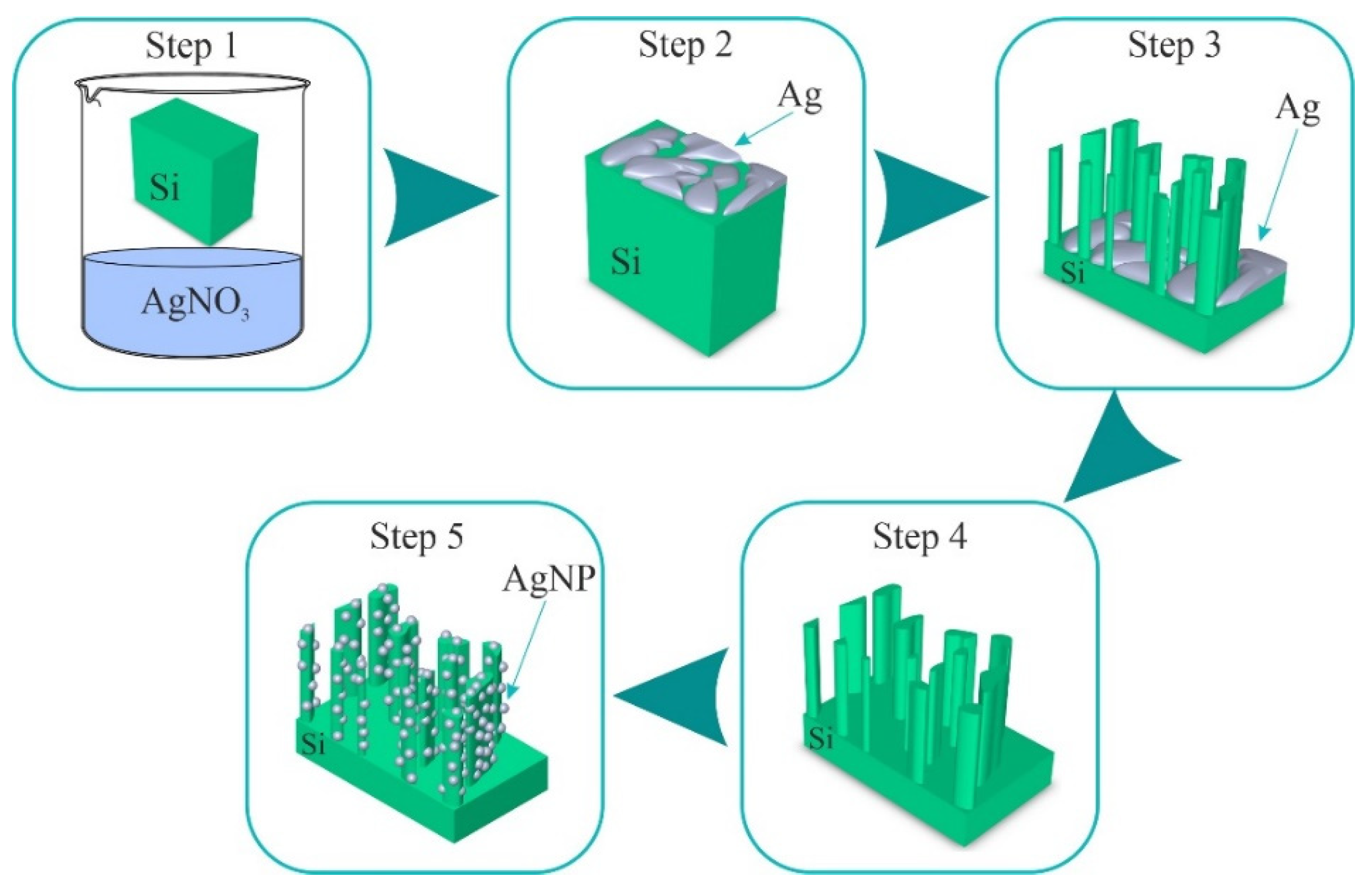
Figure 1. Schematic representation of the stages for obtaining a composite structure of Ag/SiNWs.
Coatings 12 01748 g001
Figure 2. (a) Spectral dependences of the imaginary part of the complex dielectric function ε2 defined within the framework of the Drude–Lorentz model, depending on the energy for three obtained layers of AgNPs with dAg from 2.3 to 7.8 nm; (b) SEM image of the deposited AgNP layer with thickness dAg = 7.8 nm on the Si wafer surface; the inset shows a distribution histogram of AgNPs depending on their radius, where the red line is the Gaussian distribution.
Coatings 12 01748 g002
Figure 3. XPS spectra of (a) Si2p, (b) C1s, (c) Ag3d and (d) O1s for AgNPs deposited by ALD on the surface of c-Si.
Coatings 12 01748 g003
Figure 4. Cross-section SEM images of the initial arrays of SiNWs: (a) S1 and (b) S2; and after the deposition of AgNPs by ALD method: (c) Ag/SiNWs_S1 and (d) Ag/SiNWs_S2.
Coatings 12 01748 g004
Figure 5. Experimental (exp) and calculated (calc) ellipsometric spectra (a) ψ (λ) and (b) Δ (λ) of SiNWs before (black) and after (red) AgNPs deposition for sample S1.
Coatings 12 01748 g005
Figure 6. (a) Schematic model for the structure of SiNWs (sample S1), calculated heights hSi and Si fractions fSi within the three-layer structure of composite “Si/void” sublayers according to the B-EMA model; (b) model for the Ag/SiNW structure with AgNP layers on the entire surface of SiNWs.
Coatings 12 01748 g006
Figure 7. Experimental (exp) and calculated (calc) ellipsometric spectra (a) ψ (λ) and (b) Δ (λ) of SiNWs before (black) and after (red) AgNP deposition for sample S2.
Coatings 12 01748 g007
Figure 8. (a) Electromagnetic field enhancement distribution for nanowires with Ag; (b) calculated enhancement factor of the nanowire with AgNPs as a function of wavelength.
Coatings 12 01748 g008
Table 1. Precursors for the synthesis of AgNPs by the ALD method.
Reagent AgCo-ReactantT Source, °СT Reactor, °СGrowth Per Cycle, nmRef.
(hfac)Ag(PMe3)HCHO + H2O + CH3OH63–66170–2000.007[28]
TMA H2O
0.1 M solution of ((hfac) Ag (1.5-COD) in toluenePropanol-1130125 (80–200)0.016[29]
Propanol50(110–150)[30]
Tertiary butyl hydrazine130125 (80–200)0.018[31]
Ag(fod)(PEt3)Ar + H2100130 (120–160)0.017[32]
120[33]
[34]
125[35]
125[36]
125[37]
Ar + H2 140/20 sccm106120 (120–150, 200)0.03–0.04[38]
106120[39]
Ar + H2 (20%)951300.04[40]
BH3(NHMe2)95/32110 (104–130)0.03–0.04[41]
N2/H2100, 120<0.018[42]
NH3951300.24[40]
Ag(Piv)(PEt3)Ar + H2125140–1600.12[43]
Publisher’s Note: MDPI stays neutral with regard to jurisdictional claims in published maps and institutional affiliations.