Article

Structural and Mechanical Properties of Fluorine-Containing TaCxNy Thin Films Deposited by Reactive Magnetron Sputtering

1
Department of Chemical and Materials Engineering, Center for Green Technology, Chang Gung University, Taoyuan City 33302, Taiwan
2
Department of Biomedical Engineering, National Yang Ming Chiao Tung University, Taipei 300093, Taiwan
3
Center for Plasma and Thin Film Technologies, Ming Chi University of Technology, New Taipei City 24301, Taiwan
4
Metals Research and Development Center, National Chung Hsing University, Taichung 402, Taiwan
*
Authors to whom correspondence should be addressed.
Coatings 2022, 12(4), 508; https://doi.org/10.3390/coatings12040508
Submission received: 28 February 2022 / Revised: 1 April 2022 / Accepted: 5 April 2022 / Published: 8 April 2022
(This article belongs to the Section Plasma Coatings, Surfaces & Interfaces)

Abstract

:
TaN thin-film coatings are well known for their good mechanical properties, acceptable toughness, as well as good biocompatibility. However, the friction coefficient of these films is sometimes too high, or the hemocompatibility is poor. The purpose of this study is to reduce the friction coefficient and increase the hydrophobicity of TaN coatings by introducing carbon and fluorine into the coatings. This study has never been conducted by other researchers. Fluorine-containing tantalum carbonitride (i.e., F–TaCxNy) top layers were deposited on TaN/Ta interlayers by reactive sputtering with fixed nitrogen and various hexafluoroethane (C2F6) mass flow rates. During the deposition process, C2F6 gas with various mass flow rates was added. After deposition, these F–TaCxNy multi-layered films were then characterized using XRD, XPS, FTIR, FESEM, WDS, a nano-indenter, a water contact-angle measurement system, and a tribometer. The tribological tests were carried out in the environment with and without humidity. The surface energies of the films were examined with water contact-angle variation. According to structural analysis, TaN phase would transform to TaCxNy with the increase in the C2F6 mass flow rate, which would result in a decrease in the friction coefficient and an increase in hydrophobicity. The films’ hardness (H, increased at most by 20%), elastic modulus (E), and H/E ratio first increased then decreased, most likely due to the increase in relatively soft C–F bonding. According to the results obtained from tribotesting, it was found that an increase in carbon and fluorine contents in the films reduces the friction by more than 30%, and wear rate by more than 50%. More importantly, the effects of moisture on the friction coefficient can be minimized to almost nothing. In a water contact-angle study, the contact angle increased from 60° to 85° with the increase in C2F6 mass flow rates. This evidence illustrated that hemocompatibility of the TaN thin film can be significantly enhanced through the formation of Ta–C and C–Fx bonding. The chemical composition and bonding status of these films, especially the existence of C–Fx bonds, were studied by FTIR and XPS. In sum, with the increased C2F6 mass flow rate, the carbon and fluorine contents in the films increased, while the nitrogen content decreased. The structure, bonding status, and compositions varied accordingly. The tribological behaviors were significantly improved. Furthermore, by carrying out tribotesting in humid air and a dry argon environment, it was confirmed that the greater the fluorine content, the less sensitive the films would be to environment change. This is attributable to the induced lower surface energy and reduced adsorption to water vapor due to the increase in C–Fx bonds. The successfully fabricated and studied F–TaCxNy films could be applied in many areas such as artificial blood vessels, or precision components in an atmospheric or vacuum environment.

1. Introduction

Medical devices that will have contact with blood, such as catheter, heart valves, stents, etc., are normally implanted in human bodies to solve some medical problems. To date, several approaches have been proposed to put thin coatings on implant surfaces with anti-fouling agents and albumin to decrease the adsorption of protein onto the surfaces. So far, the results are not that optimistic with regard to solving or alleviating blood-clotting issues. Therefore, more approaches to modifying the physics and chemistry of surfaces have been studied in many cases. In this respect, a surface with hydrophobic behavior should have a great potential in reducing the aggregation of adsorptive blood proteins and, hence, avoiding blood-clotting problems. However, hydrophobic surfaces may not be adherent to tissue cells either, which may cause serious problems for those implanted medical devices. Thus, there is a need to develop sustainable surfaces for medical devices that can prevent fibrinogen adsorption, reduce blood-clotting possibility, and also have good biocompatibility without compromising anti-corrosion and good mechanical properties [1].
TaN films have been used as diffusion barriers and as thin-film resistors in the electronic industries because of their highly stable structures and properties [2,3,4]. In addition, it has been reported that TaN consistently shows excellent mechanical and chemical properties [5,6], such as high oxidation- and wear-resistance, as well as better-than-average toughness. In addition, Ta metal and its alloys are also used in implantation due to their excellent biocompatibility, which makes them adjustable surface-coatings materials, particularly in bio-related applications [7,8]. This is because the surface of tantalum and its alloy may quickly form a layer of thin and inert oxide on the surface [9]. Using an MTT assay test, Huang et al. [10] showed that the adhesion of human gingival fibroblast (HGF) cells was greater than the than the adhesion of the uncoated Ti. This result proved that TaN-coated samples have a better cell attachment and proliferation rate compared with uncoated Ti. Interestingly, Leng et al. [11], as evaluated by clotting time and aggregation of platelet, compared the hemocompatibility of tantalum nitride films to that of tantalum metal, isotropic pyrolytic carbon (IPC), and titanium nitride films (TiN). They showed that the hemocompatibility of TaN films was better than that of Ta, IPC, and TiN. It was concluded in this study that TaN could be applied on artificial heart valves.
On the other hand, amorphous carbon films doped with fluorine (a–CFx) constantly exhibit interesting electrical, optical, and mechanical properties, including low wear rates and friction coefficient, together with a low surface energy [12,13]. These properties make a–CFx films potential candidates for anti-sticking and wear-resistant coatings in many engineering applications, especially in biomedical fields. It is commonly accepted that that the fluorine content determines whether the film is of diamond- or polymer-like nature which, in turn, would significantly affect the film properties. When the fluorine content is lower than 25 at.%, the a–CFx films show a biocompatible property with enhanced mechanical properties [14]. When fluorine content is more than 25 at.%, a polymer-like structure with very hydrophobic behavior would be made. The polymer-like structure has low hardness due to the increased amount of C–Fx bonds [13,15]. However, F-rich films were reported to have low stability and may be easily carbonized at relatively high temperature [16]. a–CFx’s hardness was reported as highly dependent on F concentrations. It can be between 15 GPa and 0.5 GPa [15]. Bendavid et al. [13] reported that the films’ surface energy would decrease with the increase in fluorine content and concluded that the results were caused by the variation of bonding status in the films. Particularly, it was thought to be due to the increased C–F and C–F2 bonds. The same group also tested the biocompatibility of a–CFx films using MG-63 cells. At the end, they reported good and acceptable tissue integration on a–CFx surfaces [13].
Before now, there was no report on fluorinated carbonitride coatings. It was shown through this study that these coatings could generate some advantageous properties over nitride or a–CFx. In the present study, fluorine-containing tantalum carbonitride (i.e., F–TaCxNy) thin layers were deposited with various C2F6 mass flow rate (at fixed nitrogen mass flow rate) by reactive sputtering in order to study the synergistic behaviors of TaN and a–CFx films. The combination of the above-mentioned characteristic properties may eventually widen the research and applications of fluorinated carbonitride coatings in bio-related or engineering-oriented industries.

2. Materials and Methods

2.1. Deposition

F–TaCxNy thin multilayers were fabricated using reactive co-sputtering with Ta target immersed in plasma containing Ar, N2, and C2F6 gases. The films were deposited on Si(001) and M2 tool steels substrates without additional heating. The target had a diameter of 50 mm and was tilted by 30° to the horizontal substrate holder. The distance of target to substrate was adjusted to 100 mm. In the process of deposition, the vacuum chamber was pumped down to 7 × 10⁻⁴ Pa and then Ar gas (35 sccm) was input to fill the system up to 0.65 Pa. For the preparation of substrates, they were cleaned ultrasonically in acetone (5 min.), isopropanol (5 min.), and deionized water (3 min.), then blow-dried with nitrogen. Prior to deposition, the target was first sputter cleaned using Ar plasma at a pressure of 0.65 Pa for 20 min. At this time, the target shutter was closed. At the same time, the substrates were cleaned in Ar plasma for 10 min with a bias of 80 W (RF). Within the deposition period, the power of Ta was set at 190 W and the substrate was with 40 W (RF) bias. Then, a thin Ta layer (100 nm) was laid down, followed by a 500 nm-thick TaN layer. These layers were added in order to enhance the adhesion and maintain toughness. Finally, a 500 nm-thick F–TaCxNy thin film was deposited on top. During the deposition of F–TaCxNy layer, the C2F6 mass flow rate varied from 0 to 4 sccm. The nitrogen mass flow rate was maintained at 4.5 sccm during the entire deposition process. The process parameters are listed in Table 1. The layout of the deposited layers is presented in Figure 1. During deposition, the substrate temperature reached around 60 °C at the end of deposition. Under these process parameters, the atomic ratio of C:N:F in the F–TaCxNy layer varied accordingly. The total film thickness was around 1100 nm. Film thickness was determined by a surface profiler (Surfcoder, Kosaka). The deposition rate was 10 nm/min.

2.2. Thin Film Characterization

The hardness and Young’s moduli of films were measured by a Hysitron triboindenter (TI-900, Billerica, MA, USA) equipped with a Berkovich tip. Before the tests, the tip area function was carefully calibrated using standard procedures documented by Oliver and Pharr [17]. The indentation depth was set at 50 nm [18]. The indentation was carried out in displacement control mode, while the loading rate was set 1 nm/s. Each sample was indented eight times. At the end, an average value of hardness and reduced elastic modulus was calculated. When examining the cross-sectional fracture images, these films were checked with field-emission scanning electron microscopy (SEM) (15 kV, JEOL 6700F, Akishima, Kyoto, Japan). The elemental analysis was performed by WDS (Wavelength Dispersive Spectrometer, JSM-7610F, Akishima, Kyoto, Japan). The phases and structures of the thin films were examined using an X-ray diffraction (XRD) technique. The X-ray diffractometer (XRD, Philips PW 1830, Malvern, UK) used monochromatic high intensity Cu Kα radiation (λ = 0.1541 nm). The scanning angle was from 30°-2θ to 80°-2θ, with a step size of 0.04° and a measuring time of 1.6 s per step. The vibrational modes of bonding in the prepared films were examined using Fourier-transformed-infrared spectrometer (FTIR, PerkinElmer Pentagon 1005, Waltham, MA, USA). The equipment was used to determine the infrared absorption bands within the range of 450–4000 cm−1 with a resolution of 1 cm−1 in attenuated total reflectance (ATR) mode. In the present study, the goal was to detect the existence and absorption intensity of C–Fx (x = 1,2,3) and C=C bonds. A home-made contact-angle measurement system was used to examine the films’ hydrophobicity as a function of fluorine content. The binding status of C, N, and F elements in these films was studied by X-ray photoelectron spectrometer (XPS, Microfocus Monochromatic Al anode X-ray, Thermo Fisher Scientific, Waltham, MA, USA). The C1s peak (284.6 eV) was used to calibrate the peak position. This carbon peak was obtained on gold sample surface. The carbon signal, as the energy reference, may come from the environment. The pass energy was set at 15 eV. The resolution was estimated to be 0.9 eV. Before analysis, samples were always cleaned using a 3 keV argon ion gun, until the oxygen 1s peak reached a minimum value. The chemical binding status of each element was then determined according to the spectrum.
In tribological testing, a pin-on-disc setup was used to evaluate tribological behaviors in air (RH = 90%) or a dry argon environment (RH < 5%). This setup included a pin with an alumina ball (6.35 mm in dia.) attached at the bottom hole. This pin was placed perpendicularly to the testing substrates. The substrate was controlled to rotate beneath the alumina ball at a speed of 12 cm/s. The load was set at 1 N. The sliding distance was set at the range of 500 m. When the test was complete, the friction coefficient was measured, and the wear tracks of each sample were estimated using the surface profiler. The wear rate of the sample was determined by dividing wear track volume with sliding distance. The elemental mapping of some wear tracks was conducted using EDS (Energy Dispersive Spectrometry, JEOL 6700F, Akishima, Kyoto, Japan).

3. Results and discussion

3.1. Structural Analysis

The X-ray diffraction patterns of TaN and F–TaCxNy films deposited with various C2F6 mass flow rates are presented in Figure 2. It can be observed that these films first show the typical diffraction pattern of TaN structure (C2F6 mass flow rate = 0 ~ 1 sccm). Then, TaCxNy peaks replace the TaN peaks (C2F6 mass flow rate = 2 ~ 4 sccm). According to these peak patterns, the grain size becomes larger and the preferred orientation changes from (111) to (200). This change is speculated to be caused by the need to release the strain induced by the larger F atoms embedded/entrapped in the films. The grain size, estimated by applying the Scherrer formula with (200) planes, varies from 6.8, 8.3, 11.5, 12.2, to 13.6 nm, while the C2F6 mass flow rate increases from 0, 1, 2, 3, to 4 sccm. Apparently, the formation of carbonitride will enhance crystallization. The fine grain size of TaN is not uncommon and may be attributed to energetic particle bombardment in a biased sputtering process [5].
Figure 3 shows the cross-sectional SEM micrographs of F–TaCxNy thin films deposited with various C2F6 mass flow rates. The layout of the layers is illustrated in Figure 1. The structural column size increases with the increase in the C2F6 mass flow rate. This result is consistent with those observed in the XRD study, as shown in Figure 2. The features of F–TaCxNy layers have become more obvious. This may also explain the decrease in hardness in the latter session.

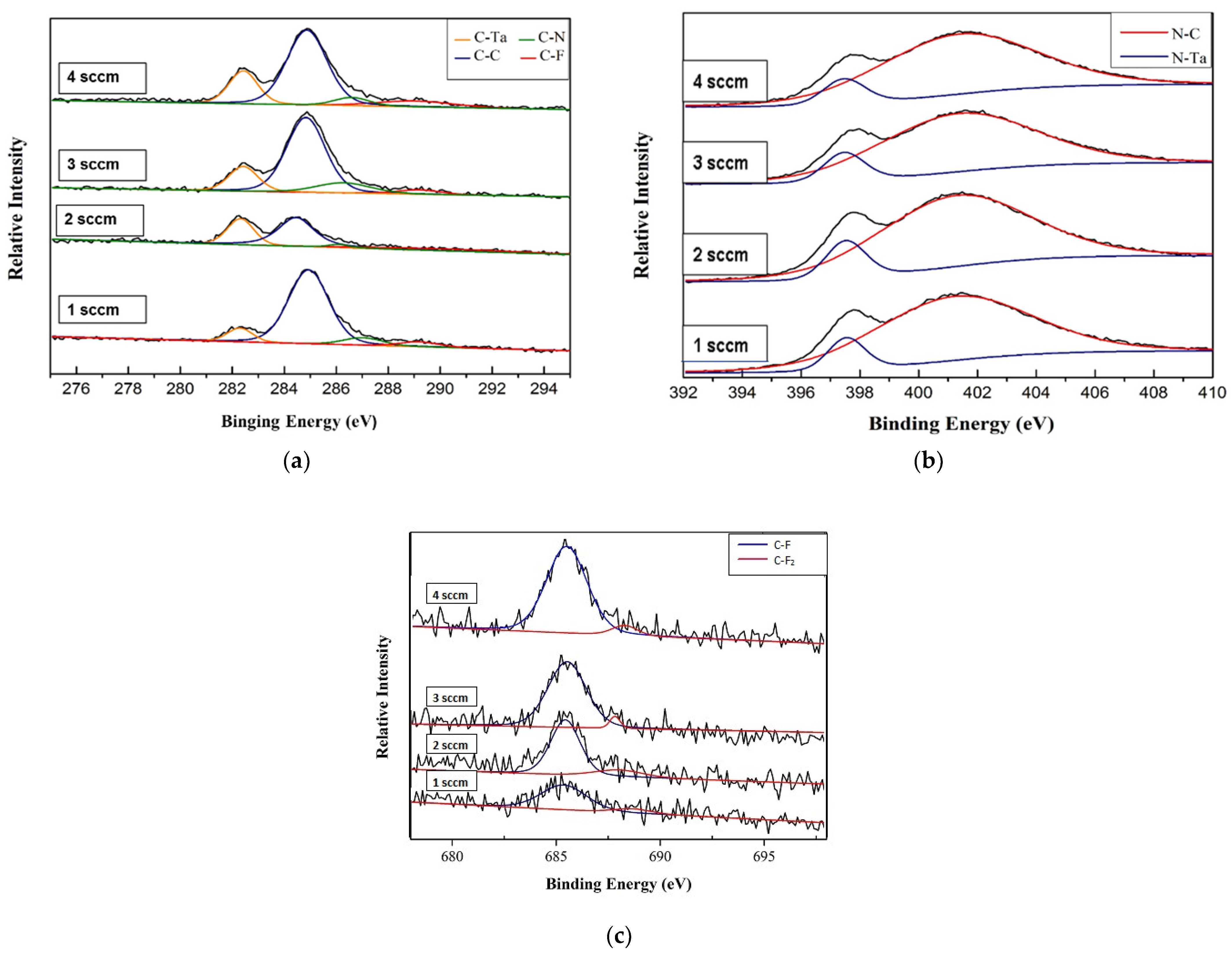
3.2. Chemical Composition and Bond Analysis

Figure 4 shows the atomic concentrations of elements, which are determined by WDS. The concentrations of C and F increase, while those of Ta and N decrease. This would eventually affect the films’ physical and chemical properties. The affected properties may include the increase and then decrease in hardness (H) and elastic modulus (E), as well as H/E. It may also enhance hydrophobic behaviors. The details are discussed in the latter section.
In order to analyze the status of chemical bonds, XPS spectra of C1s, N1s, and F1s were studied and shown in Figure 5a–c. The various binding energies for carbon bonds are shown in Figure 5a. By using a Gaussian fit, C–F (289.2 eV), C–N (286.9eV), C–C (284.8 eV), and C–Ta (282.2 eV) can be observed. The results are consistent with those obtained in previous studies [12,13]. As the fluorine content increases, the C–F peak appears to broaden and extend to a value greater than 292 eV. This could be due to more C–F bonds and the possible formation of CF2 bonds [19]. Figure 5b shows the XPS spectra of N1s. As shown in this figure, N–C and N–Ta bonds were observed. In the present study, the nitrogen concentration would decrease with the increase in carbon and fluorine. Figure 5c shows the XPS spectra of F1s. As the fluorine content increases, the C–F and C–F2 bond becomes obvious. Both peaks become sharper, which means these bonds are more in order. Furthermore, Ta concentration decreases from 50 at.% (i.e., 0 sccm C2F6) to 33 at.% (i.e., 1 sccm C2F6), then to 28 at.% (i.e., 4 sccm C2F6), as seen in Figure 4. This result implies that it is possible to form Ta5+ bonds when F and C contents increase (like Ta3N5) [20,21]. The result is consistent with the findings in the FTIR study, as seen in Figure 6. When C2F6 gas mass flow rate is at 4 sccm, the absorption bands of C–Fx, together with C–C bonds, can be observed clearly. With further analysis, it can be observed that there is a significant absorption band in the frequency range of 1000 to 1200 cm−1 as shown in the figure. These absorption bands are mainly related to the following modes that include: –C–F2 symmetric stretching mode at around 1100 cm−1, –C–F2 asymmetric stretching mode at around 1200 cm−1, and F–aryl vibration mode at around 1150 and 1260 cm−1. The band near 960 cm1 is due to the formation of the –C–F3 stretching mode [22]. As the fluorine content increases, the band becomes more pronounced and moves toward high frequency. The FTIR analysis results echoed the XPS analysis and indirectly confirmed the introduction of fluorine into the film. The broadened C–Fx bands imply that the C–Fx bond length deviated somehow from the standard C–F compound. This can be attributed to the plasma-assisted sputtering process where energetical particles constantly bombard the growing films. Regardless, the increased fluorine content will cause an increase in the water contact angle. As presented in Figure 7, the angle increases from 60° to 85°. The increase in the contact angle on F–TaCxNy films can be attributed to the increase in hydrophobic CFx groups in the films. Because of these improvements, it can be predicted that these films may have less attachment of Fibrinogen, which means that F–TaCxNy films can help avoiding blood-vessel clotting.

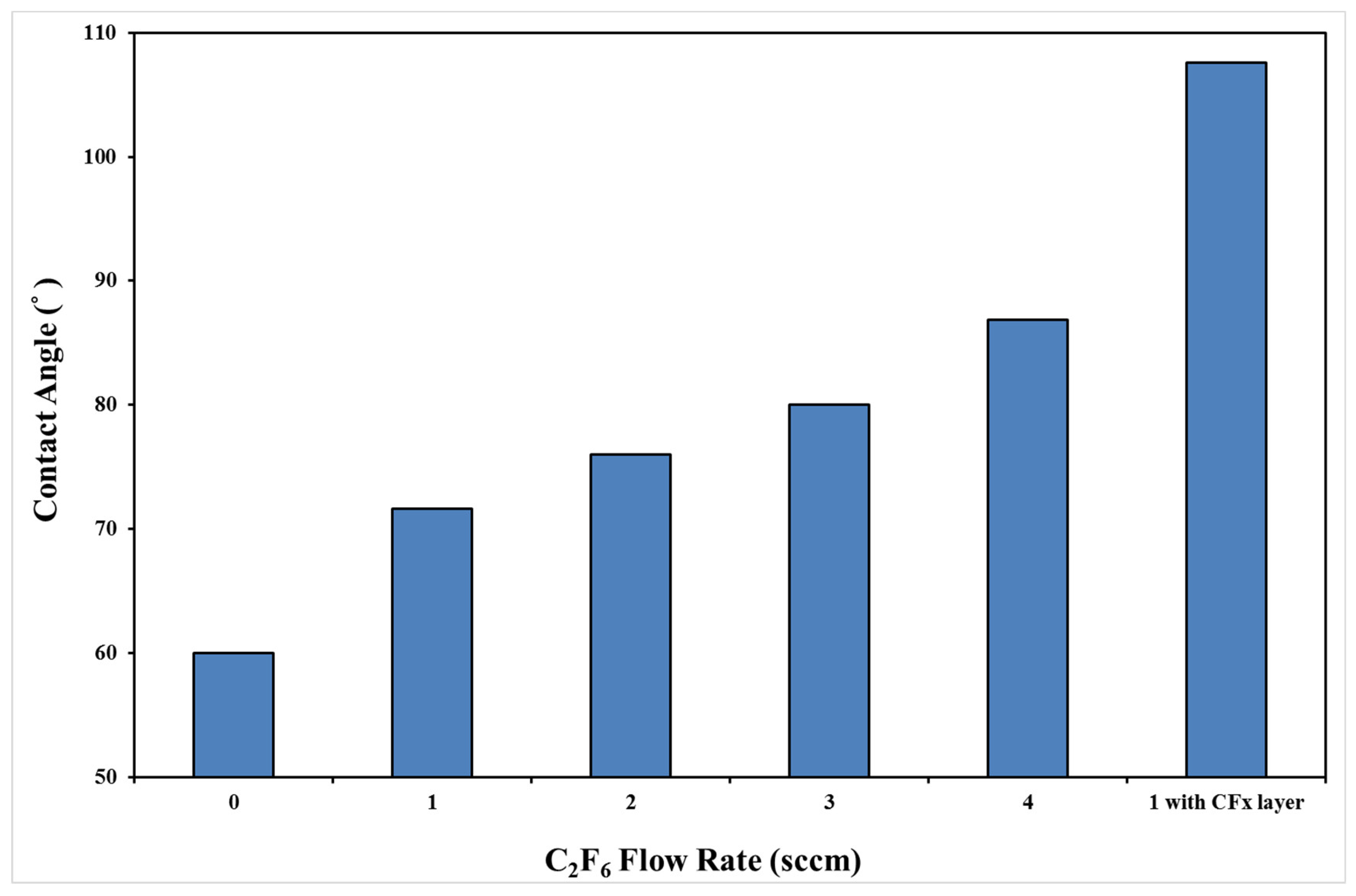
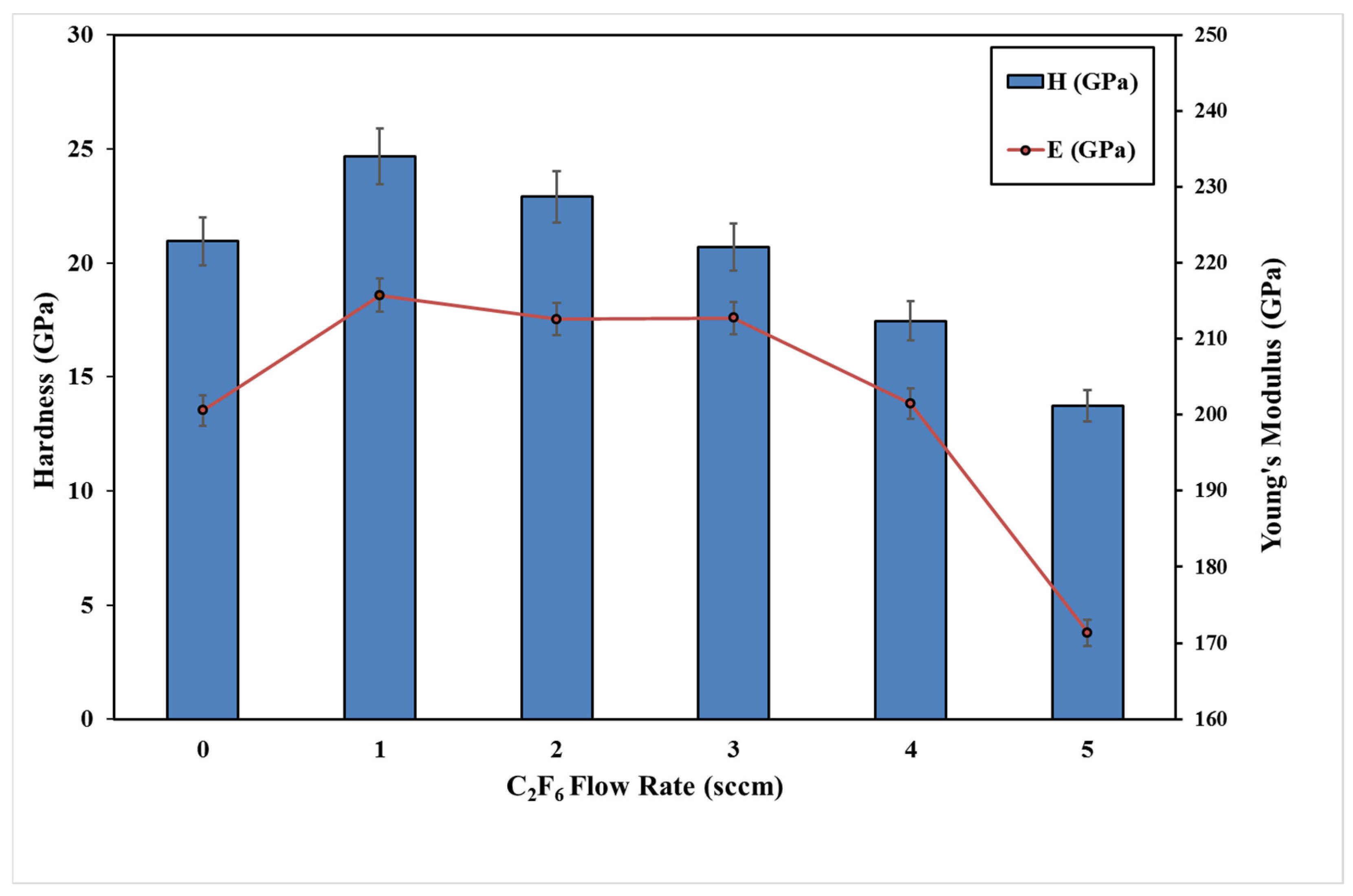
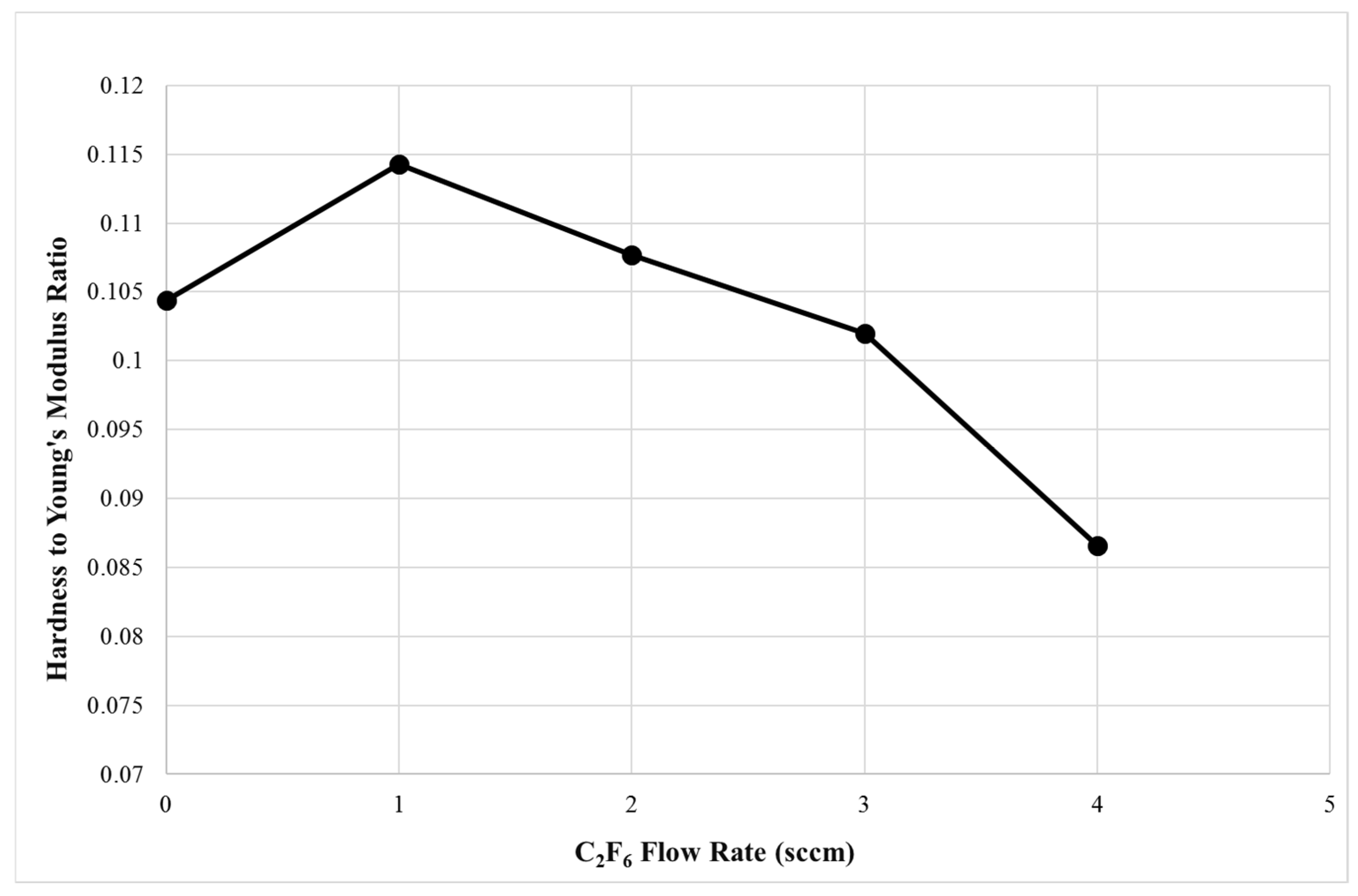
3.3. Mechanical Properties

Figure 8 shows the hardness and elastic modulus values of F–TaCxNy thin films deposited with various C2F6 mass flow rates. It is observed that the hardness and modulus values of the as-deposited samples increase with the increase in the C2F6 mass flow rate, then decrease. The highest hardness can reach about 25 GPa from 20 GPa. It is observed that the sample deposited with 1 sccm C2F6 has the highest hardness and H/E ratio (hardness to Young’s modulus). The results are presented in Figure 9. The H/E ratio is known to be proportional to the elastic strain to film failure, which may be an indicator of bending cracking resistance [23]. Therefore, a decrease in the H/E ratio can possibly contribute to an increase in wear rate. This will be discussed further, particularly for the sample deposited with 4 sccm C2F6. According to Figure 2, when the film is deposited with 1 sccm C2F6 mass flow rate, Ta–N bonds may be replaced with Ta–C bonds while maintaining their original dense TaN structure. The hardness is affected by chemical composition, density or bonding, and by film structure. The film deposited with 1 sccm C2F6 is the highest, which is also attributable to its dense film structure with little C–F bonds. The film deposited with 4 sccm C2F6 is the softest, although it has the highest carbon content. This may be due to it having a high percentage of C–F bonds which are soft.
Figure 10 shows the results obtained from the tribological testing. These tribotests were run either in humid air or in a dry Ar environment. It is observed, in general, that the friction coefficient decreases with the increase in the C2F6 mass flow rate, which in turn would result in a decrease in the wear rate. For the samples tested in a dry Ar environment, the friction coefficients are higher than those samples tested in air. However, the wear rates are found on the opposite. Those samples tested in dry Ar tend to have a lower wear rate. It is believed that, when tested in humid air, the films could be oxidized during sliding against an Al2O3 ball. The moisture in the air normally plays a critical role in oxidation wear [24]. Fortunately, it is well known that oxidative wear can be reduced when a sample is tested in a dry Ar environment. In addition to this, the introduction of fluorine into the samples shows further improvement on the tribological behaviors. One thing worth noticing is that the difference in the friction coefficient obtained from the samples tested either in Ar or in humid air diminishes with the increase in fluorine content. This means that the fluorine-containing samples are less sensitive to oxidation, or, more precisely, to moisture. Zhang et al. [25] reviewed the effects of fluorine-doped DLC’s mechanical properties and found that a change of environment, particularly moisture, does not affect the frictional behaviors of fluorinated samples. Other studies have shown similar results [26,27,28]. This mostly due to the fact that the introduction of F atoms into the films enhances the formation of CFx bonds and induces strong electronegativity on the fluorine side. These factors further produce repulsive force to the counterpart and reduce absorption of water molecules when F content reaches a critical value, which reduces the samples’ friction coefficient and sensitivity to moisture [26]. Figure 11a,b show the SEM micrographs of the wear tracks formed on the samples deposited with 1 sccm C2F6. Figure 11a is the wear track formed in the humid air, while Figure 11b is the wear track formed in the dry argon environment. When using EDS analysis, the sample tested in the air had a large accumulation of oxide debries on the track. This was not found on the sample tested in a dry argon environment. However, when the samples were deposited with 4 sccm C2F6, there was little difference found on the morphologies of wear tracks formed in either environment, as evidenced in Figure 11c,d. However, as presented in Figure 9, the sample deposited with 4 sccm C2F6 had a low H/E ratio, which means the film is more prone to microcracking during wear testing. However, due to its richness in fluorine, the friction coefficient, and hence the wear rate, is lower. Figure 11e shows the elemental mapping of the track shown in Figure 11d. It can be observed that the track is rich in F (green color) and C (blue color). Some oxygen signals are found on the surface. The thin oxide layer may be formed prior to wear testing. Overall, according to the examination on wear tracks, it can be concluded that CFx bonds would help reduce oxidative wear. This may be attributed to their hydrophobic behavior due to the existence of fluoride and the formation of repulsive force.

4. Conclusions

Fluorine-containing TaCxNy thin films were prepared using reactive co-sputtering with various C2F6 mass flow rates. The films had various structural characteristics, mechanical properties and surface behaviors depending on their chemical composition, particularly their fluorine content. According to WDS, FTIR, and XPS studies, it is confirmed that C–Fx bonds can exist in these films. The amount of C–Fx bonds increase with the increase in the C2F6 mass flow rate. This directly affects the properties of these films. For the sample deposited with 1 sccm C2F6, hardness (H), elastic modulus (E), and H/E ratio all reach the maximum. The films’ hardness, elastic modulus, and H/E ratio first increased then decreased, most likely due to the increased formation of relatively soft C–F bonding. The water contact angle increases with the increase in the C2F6 gas mass flow rate. This in turn affects the tribological behaviors of F–TaCxNy films. By testing the samples in a humid air and dry argon environment, it is confirmed that the sample rich in fluorine content has a lower friction coefficient and wear rate and is less sensitive to humidity change. According to the results obtained from tribotesting, it is found that an increase in carbon and fluorine content in the films reduces the friction by more than 30%, and wear rate by more than 50%. More importantly, the effects of moisture on friction coefficient can be minimized to almost nothing. This can be attributed to the increase in C–Fx bonds, which induces low surface energy and high moisture-repulsive force. The improvement of hydrophobic behaviors may imply that the film has reduced attachment of fibrinogen protein, which means it will be less prone to blood clotting. In summation, the present study illustrated that hemocompatibility of the TaN thin film can be significantly enhanced through the formation of Ta–C and C–Fx bonding. With the increase in the C2F6 mass flow rate, the carbon and fluorine contents in the films increase, while nitrogen content decreases. The structure, bonding status, and compositions vary accordingly. The tribological behaviors are significantly improved. Furthermore, by carrying out tribotesting in a humid air and dry argon environment, it was confirmed that with greater fluorine content, the films would be less sensitive to environment change. This can be attributed to the induced lower surface energy and reduced adsorption of water vapor due to the increase in C–Fx bonds. The successfully fabricated and studied F–TaCxNy films could be applied in many areas such as artificial blood vessels and precision components in an atmospheric or vacuum environment.

Author Contributions

Conceptualization, J.-H.H. and C.L.; methodology, J.-H.H. and W.W.; validation, J.-H.H. and C.L.; investigation, S.-L.L.; writing—original draft preparation, J.-H.H.; writing—review and editing, C.L.; supervision, J.-H.H.; project administration, J.-H.H.; funding acquisition, J.-H.H. All authors have read and agreed to the published version of the manuscript.

Funding

This work was supported in part by the Ministry of Science and Technology, Taiwan under Grant MOST 105-2221-E-131 -003 -MY2.

Institutional Review Board Statement

Not applicable.

Informed Consent Statement

Not applicable.

Data Availability Statement

Data is contained within the article.

Conflicts of Interest

The authors declare no conflict of interest.

References

  1. Manivasagam, V.K.; Popat, K.C. In Vitro Investigation of Hemocompatibility of Hydrothermally Treated Titanium and Titanium Alloy Surfaces. ACS Omega 2020, 5, 8108–8120. [Google Scholar] [CrossRef] [PubMed]
  2. Li, Z.; Zhang, Y.; Wang, Y.; Li, J.; Zhao, H. Effect of Nitrogen Flow Ratio on Degradation Behaviors and Failure of Magnetron Sputter Deposited Tantalum Nitride. Coatings 2021, 11, 1133. [Google Scholar] [CrossRef]
  3. Zaman, A.; Meletis, E.I. Microstructure and Mechanical Properties of TaN Thin Films Prepared by Reactive Magnetron Sputtering. Coatings 2017, 7, 209. [Google Scholar] [CrossRef] [Green Version]
  4. Radhakrishnan, K.; Ing, N.G.; Gopalakrishnan, R. Reactive sputter deposition and characterization of tantalum nitride thin films. Mater. Sci. Eng. 1999, 57, 224–227. [Google Scholar] [CrossRef]
  5. Dai, W.; Shi, Y. Effect of Bias Voltage on Microstructure and Properties of Tantalum Nitride Coatings Deposited by RF Magnetron Sputtering. Coatings 2021, 11, 911. [Google Scholar] [CrossRef]
  6. Stavrev, M.; Fischer, D.; Wenzel, C.; Drescher, K.; Mattern, M. Crystallographic and morphological characterization of reactively sputtered Ta, TaN, TaNO thin films. Thin Solid Film. 1997, 307, 79–88. [Google Scholar] [CrossRef]
  7. Ratner, B.D.; Hoffman, A.S.; Schoen, F.J.; Lemons, J.E. Biomaterials Science, 2nd ed.; Elsevier: Cambridge, MA, USA, 2004. [Google Scholar]
  8. Balla, V.K.; Bodhak, S.; Bose, S.; Bandyopadhyay, A. Porous tantalum structures for bone implants: Fabrication, mechanical and in vitro biological properties. Acta Biomater. 2010, 6, 3349–3359. [Google Scholar] [CrossRef] [Green Version]
  9. Zitter, H.; Plenk, H., Jr. The electrochemical behavior of metallic implant materials as an indicator of their biocompatibility. J. Biomed. Mater. Res. 1987, 21, 881–896. [Google Scholar] [CrossRef]
  10. Huang, H.L.; Chang, Y.Y.; Lai, M.C.; Lin, C.R.; Lai, C.H.; Shieh, T.M. Antibacterial TaN-Ag coatings on titanium dental implants. Surf. Coat. Technol. 2010, 205, 1636–1641. [Google Scholar] [CrossRef]
  11. Leng, Y.X.; Sun, H.; Yang, P.; Chen, J.Y.; Wang, J.; Wan, G.J.; Huang, N.; Tian, X.B.; Wang, L.P.; Chu, P.K. Biomedical properties of tantalum nitride films synthesized by reactive magnetron sputtering. Thin Solid Film. 2001, 398–399, 471–475. [Google Scholar] [CrossRef]
  12. Piallat, F.; Beugin, V.; Gassilloud, R.; Michallon, P.; Dussault, L.; Pelissier, B.; Asikainen, T.; Maes, J.W.; Martin, F.; Morin, P.; et al. Evaluation of plasma parameters on PEALD deposited TaCN. Microelectron. Eng. 2013, 107, 156–160. [Google Scholar] [CrossRef]
  13. Bendavid, A.; Martin, P.J.; Randeniya, L.; Amin, M.S.; Rohanizadeh, R. The properties of fluorine-containing diamond-like carbon films prepared by pulsed DC plasma-activated chemical vapour deposition. Diam. Relat. Mater. 2010, 19, 1466–1471. [Google Scholar] [CrossRef]
  14. Schmidt, S.; Goyenola, C.; Gueorguiev, G.K.; Jensen, J.; Greczynski, G.; Ivanov, I.G.; Czigány, Z.; Hultman, L. Reactive high power impulse magnetron sputtering of CFx thin films in mixed Ar/CF4 and Ar/C4F8 discharges. Thin Solid Film. 2013, 542, 21–30. [Google Scholar] [CrossRef]
  15. Schmidt, D.S.; Greczynski, G.; Goyenola, C.; Gueorguiev, G.K.; Czigany, Z.; Jensen, J.; Ivanov, I.G.; Hultman, L. CFx thin solid films deposited by high power impulse magnetron sputtering: Synthesis and characterization. Surf. Coat. Technol. 2011, 206, 646–653. [Google Scholar] [CrossRef] [Green Version]
  16. Nobili, E.L.; Guglielmini, A. Thermal stability and mechanical properties of fluorinated diamond-like carbon coatings. Surf. Coat. Technol. 2013, 219, 144–150. [Google Scholar]
  17. Oliver, W.C.; Pharr, G.M. An improved technique for determining hardness and elastic modulus using load and displacement sensing indentation experiments. J. Mater. Res. 1992, 7, 1564–1583. [Google Scholar] [CrossRef]
  18. Chen, J.; Bull, S.J. On the factors affecting the critical indenter penetration for measurement of coating hardness. Vacuum 2009, 83, 911–920. [Google Scholar] [CrossRef]
  19. Yao, Z.Q.; Yang, P.; Huang, N.; Sun, H.; Wang, J. Structural, mechanical and hydrophobic properties of fluorine-doped diamond-like carbon films synthesized by plasma immersion ion implantation and deposition (PIII–D). Appl. Surf. Sci. 2004, 230, 172–178. [Google Scholar] [CrossRef]
  20. Arshi, N.; Lu, J.; Joo, Y.K.; Yoon, J.H.; Koo, B.H. Effects of nitrogen composition on the resistivity of reactively sputtered TaN thin films. Surf. Interface Anal. 2015, 47, 154–160. [Google Scholar] [CrossRef]
  21. Li, L.; Niu, E.; Lv, G.; Zhang, X.; Chen, H.; Fan, S.; Liu, C.; Yang, S.Z. Synthesis and electrochemical characteristics of Ta–N thin films fabricated by cathodic arc deposition. Appl. Surf. Sci. 2007, 253, 6811–6816. [Google Scholar] [CrossRef]
  22. Wang, X.; Harris, H.R.; Bouldin, K.; Temkin, H.; Gangopadhyay, S. Structural properties of fluorinated amorphous carbon films. J. Appl. Phys. 2000, 87, 621–623. [Google Scholar] [CrossRef] [Green Version]
  23. Leyland, A.; Matthew, A. On the sigficance of H/E ratio in wear control: A nanocomposite coating approach to optimized tribological behavior. Wear 2000, 246, 1–11. [Google Scholar] [CrossRef]
  24. Hong, S.; Li, J.; Zhao, P.; Xu, Y.; Li, W. Evolution in Wear and High-Temperature Oxidation Resistance of Laser-Clad AlxMoNbTa Refractory High-Entropy Alloys Coatings with Al Addition Content. Coatings 2022, 12, 121. [Google Scholar] [CrossRef]
  25. Zhang, L.; Wang, F.; Qiang, L.; Gao, K.; Zhang, B.; Zhang, J. Recent advances in the mechanical and tribological properties of fluorine-containing DLC films. RSC Adv. 2015, 5, 9635–9649. [Google Scholar]
  26. Yamada, N.; Kato, Y.; Kanda, K.; Haruyama, Y.; Matsui, S. Surface modification of diamond-like carbon by synchrotron radiation exposure under the perfluorohexane gas atmosphere. Jpn. J. Appl. Phys. Part 1 2006, 45, 6400. [Google Scholar] [CrossRef]
  27. Nakamura, T.; Ohana, T.; Suzuki, M.; Ishihara, M.; Tanaka, A.; Koga, Y. Surface modification of diamond-like carbon films with perfluorooctyl functionalities and their surface properties. Surf. Sci. 2005, 580, 101–106. [Google Scholar] [CrossRef]
  28. Zhang, L.; Zong, X.; Guo, F.; He, B.; Yuan, X. Effect of fluorine incorporation on DLC films deposited by pulsed cathodic arc deposition on nitrile butadiene rubber and polyurethane rubber substrates. Coatings 2020, 10, 878. [Google Scholar] [CrossRef]
Figure 1. Layout of the film structure.
Coatings 12 00508 g001
Figure 2. X-ray diffraction patterns of TaN film and F–TaCxNy films with TaCxNy structure.
Coatings 12 00508 g002
Figure 3. Cross-sectional SEM micrographs of F–TaCxNy films deposited with various C2F6 mass flow rate: (a) 0 sccm; (b) 1 sccm; (c) 2 sccm; (d) 3 sccm; (e) 4 sccm.
Coatings 12 00508 g003
Figure 4. Chemical compositions of F-TaCxNy films deposited with various C2F6 mass flow rate.
Coatings 12 00508 g004
Figure 5. XPS spectra of (a) C1s; (b) N1s; and (c) F1s.
Coatings 12 00508 g005
Figure 6. FTIR spectra of various F–TaCxNy films, as a function of C2F6 mass flow rate.
Coatings 12 00508 g006
Figure 7. Water contact angle on F–TaCxNy films.
Coatings 12 00508 g007
Figure 8. Hardness and Young’s modulus values vs. C2F6 mass flow rate.
Coatings 12 00508 g008
Figure 9. Ratios of Hardness to Young’s modulus vs. C2F6 mass flow rate.
Coatings 12 00508 g009
Figure 10. Friction coefficient and wear rate of F–Ta–CxNy films tested in humid air and dry argon environment.
Coatings 12 00508 g010
Figure 11. Wear tracks of the sample deposited with 1 and 4 sccm C2F6: (a) and (c) tested under humid air, (b) and (d) tested under a dry argon environment; (e) elemental mapping of (d).
Coatings 12 00508 g011
Table 1. Process parameters for depositing F–TaCxNy films.
Process Parameters
Power of Ta target (W)(DC) 190
RF Bias (W)(RF) 50
Target–substrate distance (cm)10
Background pressure (torr)4 × 10⁻⁶
Flow Rate of Ar (sccm)35
Flow Rate of N2 (sccm)4.5
Flow Rate of C2F6 (sccm)0/1/2/3/4
Publisher’s Note: MDPI stays neutral with regard to jurisdictional claims in published maps and institutional affiliations.

