
A Study on the Influence of End-Sheath Aging and Moisture Absorption on Abnormal Heating of Composite Insulators


 ,
,
Abstract
:1. Introduction
2. Samples and Test Methods
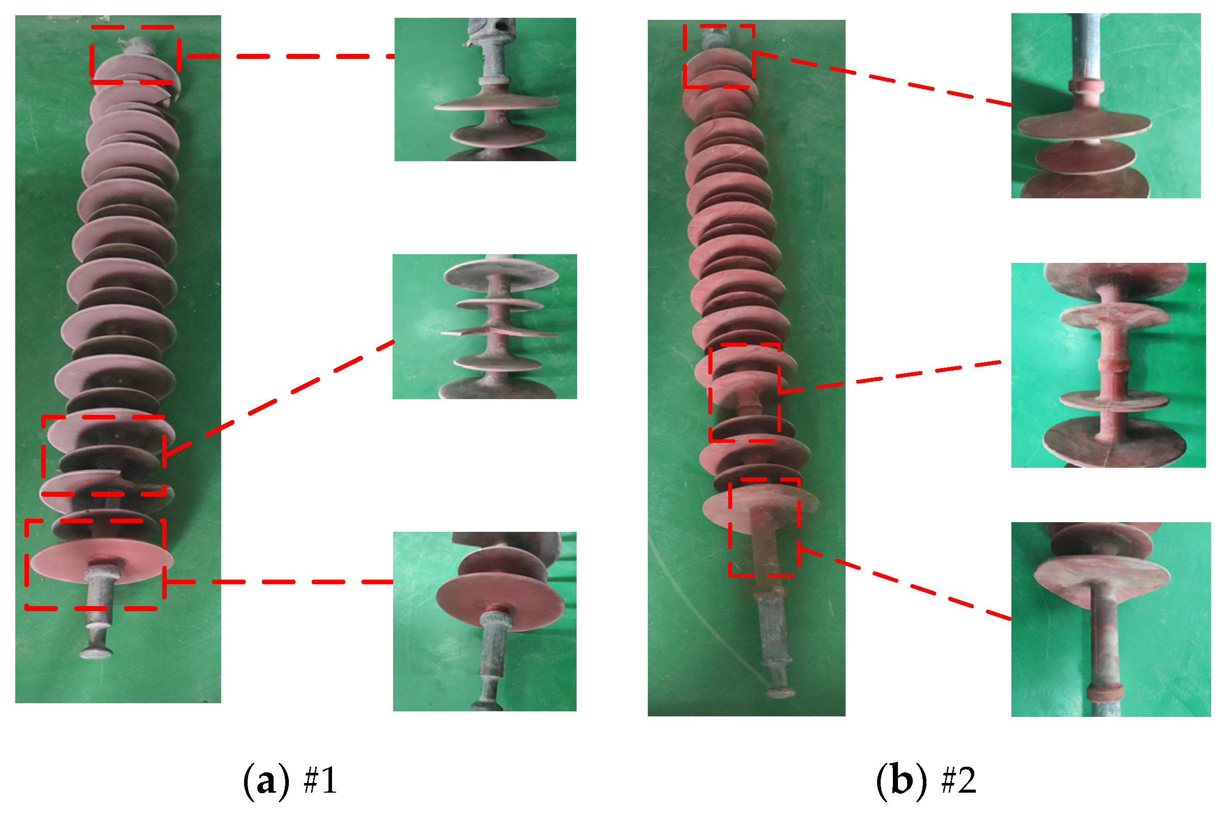
2.1. Samples
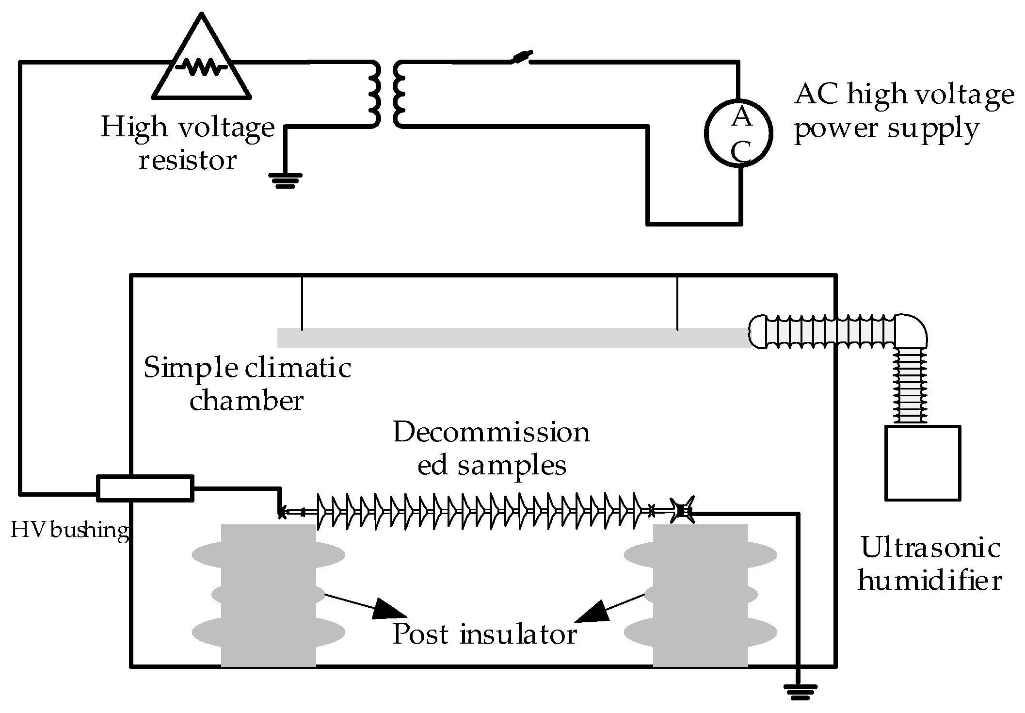
2.2. Test Scheme
- Before the test started, the composite insulator samples were placed in the climatic chamber, the mist amount of the ultrasonic humidifier (Wetwells, Hangzhou, China) was adjusted by rotating the knob so the ambient humidity reached the set value, and the samples were stabilized at this state for 30 min to ensure uniform distribution of humidity in the climatic chamber;
- When humidity was 30% RH (ambient humidity), the AC voltage with an effective value of 70 kV (110 kV × 1.1/) was applied to the composite insulator samples, and the temperature rise in the sample was recorded every 15 min. The temperature rises in the samples reached stable levels after the voltage was applied for 60 min, and the temperature rises in the samples were recorded;
- In an environment with 55% RH, the insulator samples were placed for 72 h for full moisture absorption, and the AC voltage with an effective value of 70 kV was applied to the samples. After the voltage was applied for 60 min, the temperature rise in the sample reached a stable level, which was recorded;
- Step 3 was repeated for the composite insulator samples in an environment with 75% RH and 95% RH.
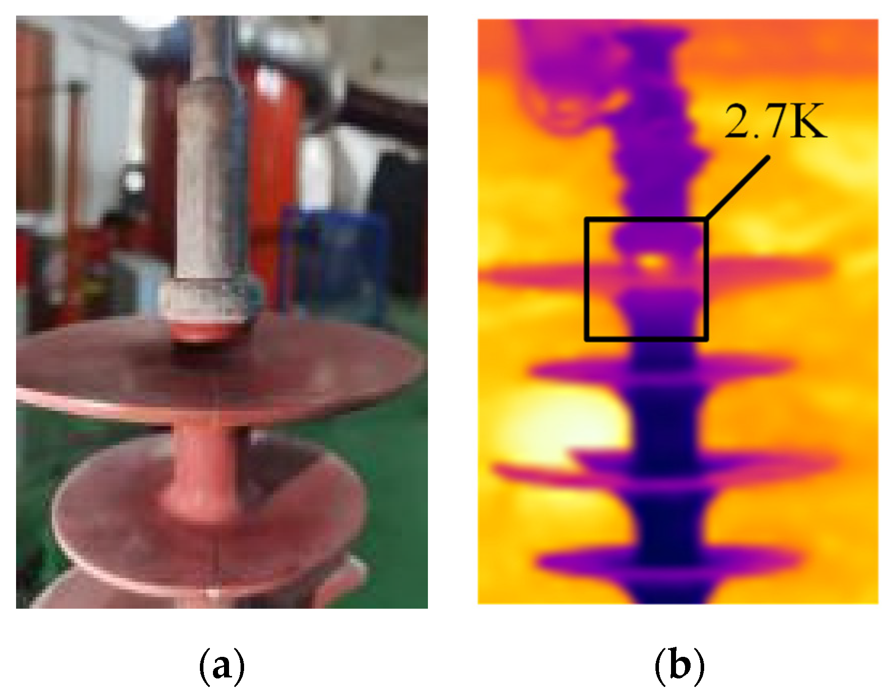
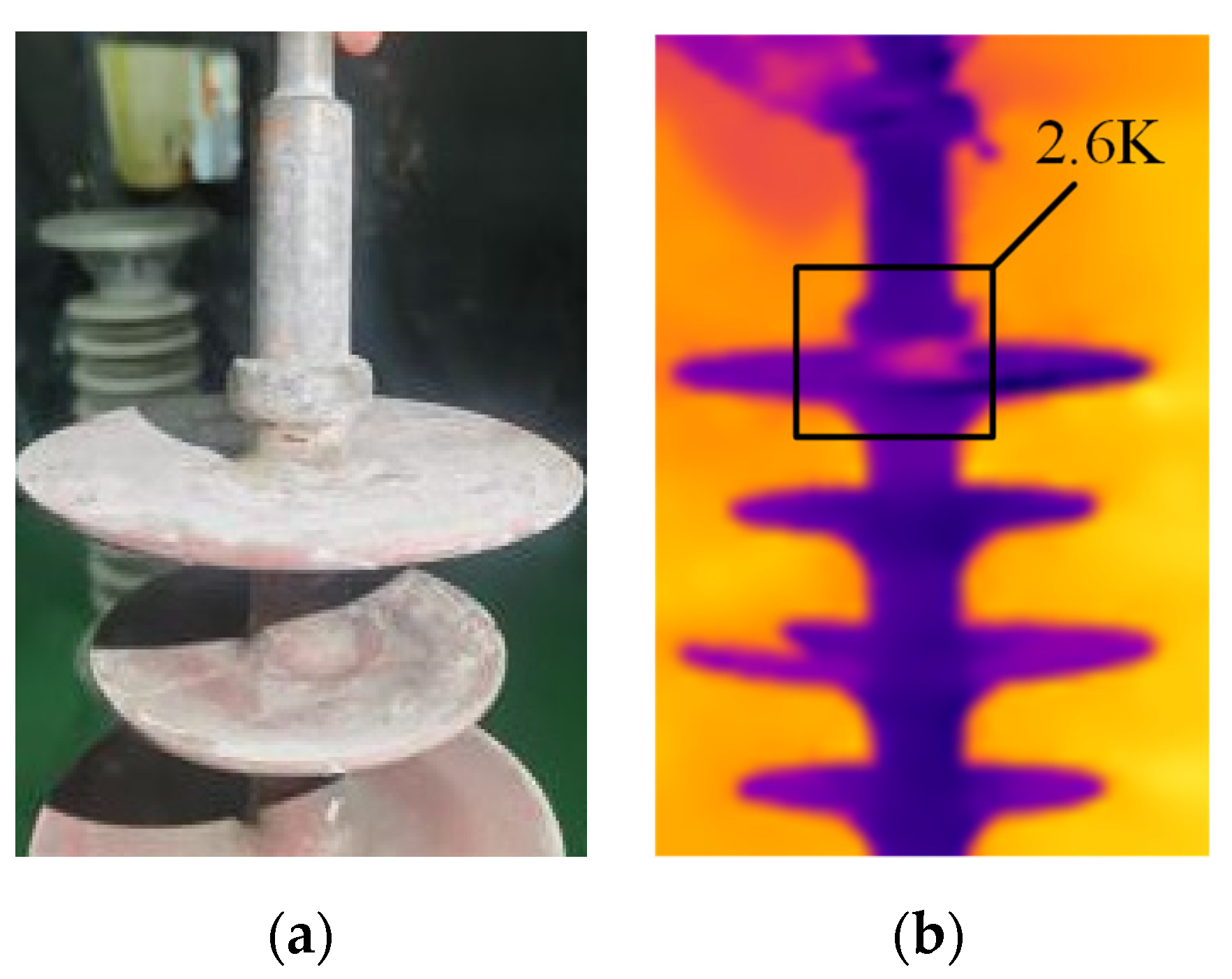
3. Infrared Temperature Rise Test
4. Cause Analysis of Sample Heating
4.1. Influence of High-Voltage End Contamination on Composite Insulator Heating
4.2. Influence of Aging and Moisture Absorption of Sheath Surface on Dielectric Properties of Composite Insulators
5. Simulation Analysis of Causes of Abnormal Heating of Composite Insulators
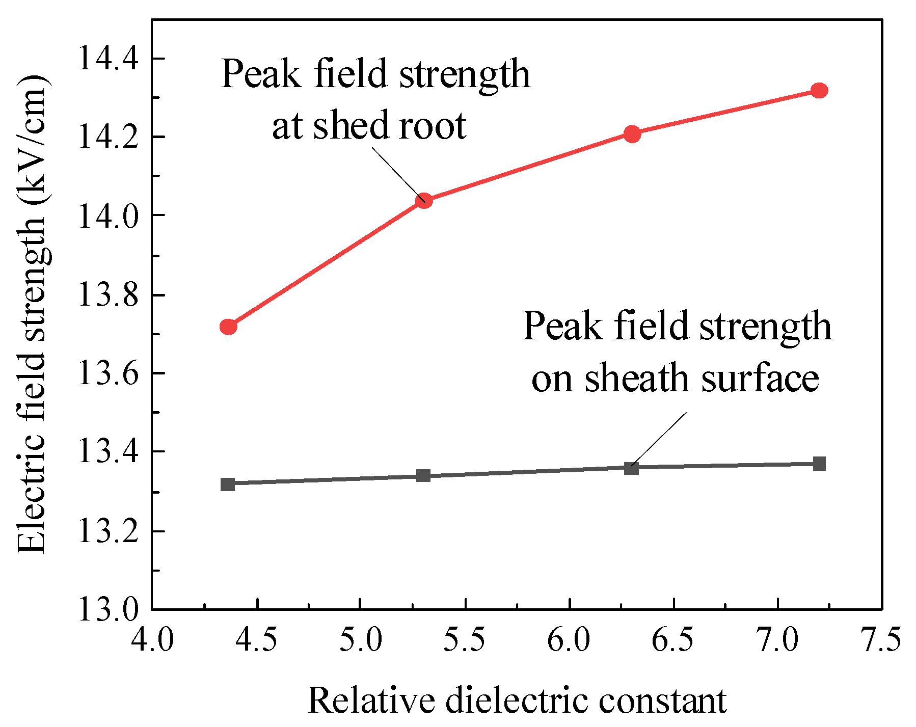
5.1. Comparison of Electric Field at High-Voltage End of Composite Insulators before and after Moisture Absorption
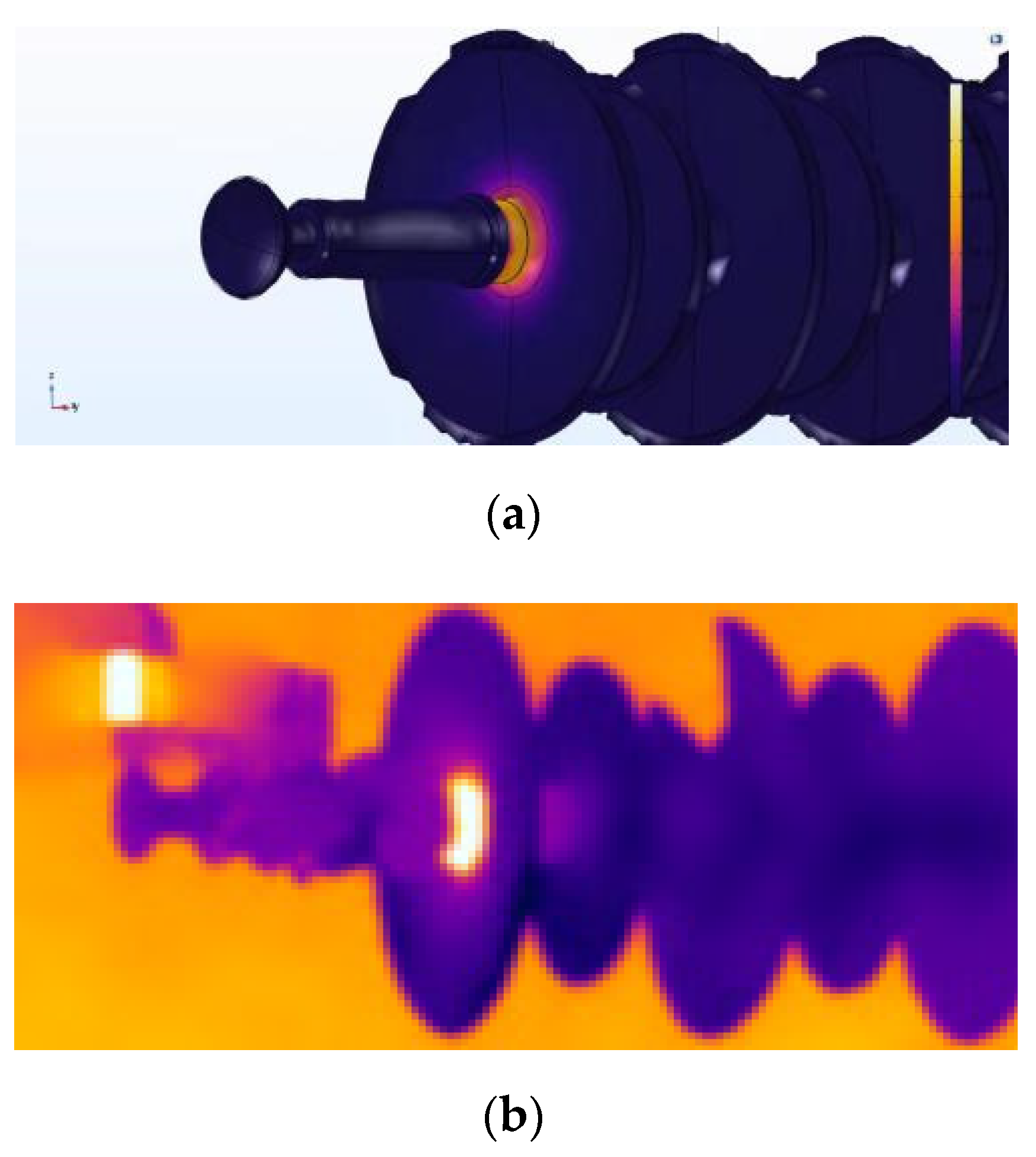
5.2. Comparison of Temperature Field at High-Voltage End of Composite Insulators after Moisture Absorption
6. Conclusions
- (1)
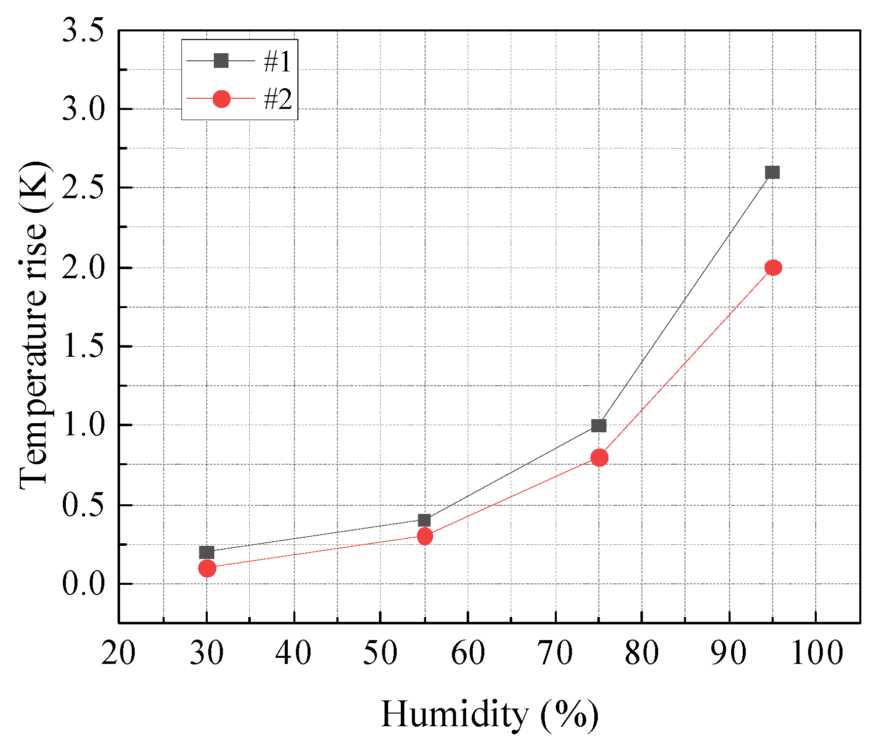
- The abnormal heating of two typical 110 kV composite insulators detected in this study occurred at the high-voltage end, and temperature rise increased with ambient humidity. In low-humidity environments, the peak temperature rise in composite insulators was less than 0.5 K, without obvious heating; the highest temperature of the sample reached about 1.0 K in an environment with 75% RH; the peak temperature rise in the two samples reached 2.6 and 2.0 K, respectively, in an environment with 95% RH;
- (2)
- It was concluded that surface contamination was not the main cause of abnormal heating of decommissioned composite insulator samples based on a comparison of the changes in the surface temperature rise in composite insulator samples before and after surface contamination cleaning and before and after recoating with grade IV contamination;
- (3)
- The aging of the high-voltage end sheath was more obvious than that of the medium- and low-voltage ends, and its dielectric constant and dielectric loss factors were 1.14 and 2.11 times those of the medium-voltage end-sheath material, respectively. The dielectric constant and dielectric loss factors of the high-voltage end-sheath surface after aging and moisture absorption in high-humidity environments further increased to 1.65 and 9.92 times those in a dry environment. Combined with finite element simulation analysis, it was concluded that the partial electric field on the high-voltage end-sheath surface was distorted after aging and moisture absorption in high-humidity environments, and this caused the maximum value of the partial electric field to increase by about 4.1%. Therefore, the dielectric loss (leakage conductance loss and lossy polarization loss) caused by aging and moisture absorption of the sheath surface under partial high field strength was the leading cause of abnormal heating at the high-voltage end of composite insulators;
- (4)
- According to the comparison of the temperature rise and abnormal heating positions of composite insulators in an infrared temperature rise test and electrothermal coupling simulation, the test results and simulation results were basically consistent, further verifying the dielectric loss after aging and moisture absorption of the sheath surface was the leading cause of abnormal heating at the high-voltage end of composite insulators.
Author Contributions
Funding
Institutional Review Board Statement
Informed Consent Statement
Data Availability Statement
Conflicts of Interest
References
- Jiangliu, C.; Zhiyi, S.; Hui, Y. The application and its prospect of silicone rubber composite insulators in China. Electr. Power 1999, 1, 40–43. [Google Scholar]
- Liang, X.; Gao, Y.; Wang, J.; Li, S. Rapid development of silicone rubber composite insulator in China. High Volt. Eng. 2016, 42, 2888–2896. [Google Scholar]
- Guan, Z.C.; Peng, G.M.; Wang, L.M.; Jia, Z.D.; Zhang, R.B. Application and key technical study of composite insulators. High Volt. Eng. 2011, 37, 513–519. [Google Scholar]
- Hackam, R. Outdoor HV composite polymeric insulators. IEEE Trans. Dielectr. Electr. Insul. 1999, 6, 557–585. [Google Scholar] [CrossRef]
- Zehong, L. Present situation and prospects of applying composite insulators to UHF transmission lines in China. Power Syst. Technol. 2006, 12, 1–7. [Google Scholar]
- Zheng, W.; Zhen, H.; Xiangyang, P. Abnormal aged characteristics and causes of sheath-core interface in composite insulators. Insul. Mater. 2022, 55, 112–118. [Google Scholar]
- Zhang, F.; Song, L.; Tu, Y.; Xu, Z.; Li, R.; Wang, G. Analysis of operating performance for the 500kV composite insulator. High Volt. Eng. 2012, 38, 2536–2541. [Google Scholar]
- Zhen, H.; Zhihai, X.; Xiangyang, P. Sampling inspection experiment on operating state of transmission line composite insulator. Guangdong Electr. Power 2017, 30, 114–118. [Google Scholar]
- Yangchun, C.; Chengrong, L.; Mian, C. Research on heating mechanism of composite insulator of high voltage transmission line. Power Syst. Technol. 2005, 05, 57–60. [Google Scholar]
- Huang, Z.; Zhang, Z.; Peng, X.; Yang, C.; Wang, R.; Lv, H.; Wang, L. Analysis on surface abnormal heating and the countermeasure for composite insulators. Insul. Surge Arresters 2020, 6, 171–175. [Google Scholar]
- Wang, L.; Zhang, Z.; Cheng, L.; Zhang, F.; Mei, H. Effect of damp sheath on abnormal temperature rise at end of composite insulator. Power Syst. Technol. 2016, 40, 608–613. [Google Scholar]
- Wang, L.; Fu, K.; Mei, H.; Zhang, F.Z.; Guo, C.J.; Zhang, Z. Influence of environmental humidity on infrared measurement temperature of composite insulators. High Volt. Eng. 2019, 45, 1955–1961. [Google Scholar]
- Zulin, W.; Tao, H.; Yan, L. On-line inspection of defective composite insulators by infrared temperature measurement. Power Syst. Technol. 2003, 2, 17–20. [Google Scholar]
- Lu, M.; Zhang, Z.; Li, L.; Liu, Z.; Hua, K.; Yang, X. Reason analysis of decay-like aging for composite insulator. Power Syst. Technol. 2018, 42, 1335–1341. [Google Scholar]
- Application Rules of Infrared Diagnosis for Live Electrical Equipment: DL/T664-2016; Infraspection Institutes: Burlington, NJ, USA, 2016.
- Environmental Pollution Classification and External Insulation Selection for High Voltage Transmission Line, Power Plant and Substation: GBT16434-1996; State Technical Supervision Bureau: Beijing, China, 1996.
- Tu, Y.; Chen, C.; Tong, Y.; Zhang, H.; Lu, Y.; Xie, L. Aging characteristics of shed materials of silicone rubber composite insulators in service. High Volt. Eng. 2012, 38, 2522–2527. [Google Scholar]
- Wenwei, S.; Wei, S.; Guoli, W. Influence of corona discharge on aging characteristics of HTV silicone rubber material. High Volt. Appar. 2013, 49, 1–7. [Google Scholar]
- Zhikang, Y. Deterioration Characteristics and Mechanism of Materials in Composite Insulator under High Humidity; North China Electric Power University: Beijing, China, 2019. [Google Scholar]
- Jiang, X.L.; Xia, Q.F.; Hu, Q.; Shu, L.C.; Sun, C.X. Influence of deteriorated insulator on the electric field distribution of overhang string. Proc. CSEE 2010, 30, 118–124. [Google Scholar]
- Pipei, Z. Infrared detection and thermoelectric coupling simulation analysis of 220 kV insulator abnormal heating. J. Phys. Conf. Ser. 2020, 1659, 12031. [Google Scholar]


| Sample No. | Model | Structure Height (mm) | Number of Sheds (Big/Small Sheds) | Mandrel Diameter (Including Sheath) (mm) |
|---|---|---|---|---|
| #1 | FXBW-110/100 | 124 | 27(14/13) | 28 |
| #2 | FXBW-110/100 | 134 | 23(12/11) | 28 |
| Test Humidity | Test Conditions | Temperature Rise/K |
|---|---|---|
| High humidity (95% RH) | Without treatment | 2.6 |
| Surface contamination cleaning | 2.7 | |
| The parts in front of three sheds and sheaths at the high-voltage end were recoated with grade IV contamination | 2.6 |
| The Main Parameters | |
|---|---|
| Model | NOVOCONTROL |
| Temperature range | −160~400 °C |
| Frequency range | 3 × 10⁻⁶~3 × 10⁹ Hz |
| Impedance range | 10 mΩ~100 TΩ |
| Capacitance range | 1 fF~1 F |
| Phase difference accuracy | 2 × 10⁻³ |
| Tan(δ) accuracy | 3 × 10⁻⁵ |
| Measuring voltage | 10−6~3 V |
| DC bias voltage range | ±40 V |
| Location | Dielectric Constant | Dielectric Loss Factor | ||
|---|---|---|---|---|
| Before Moisture Absorption | After Moisture Absorption | Before Moisture Absorption | After Moisture Absorption | |
| High-voltage end | 4.36 | 7.20 | 1.30% | 12.90% |
| Medium-voltage end | 4.16 | 6.30 | 0.60% | 6.10% |
| Low-voltage end | 4.18 | 6.71 | 0.59% | 6.52% |
| Parameters | Values | Parameters | Values |
|---|---|---|---|
| ω | 100 π rad/s | h | 5 W/(m2·°C) |
| ε | 7.2 | ε1silicone rubber | 0.95 |
| λmetal | 49.8 W/(m·°C) | σ | 5.67 × 10⁻⁸ W/(m2·°C4) |
| λsilicone rubber | 2 W/(m·°C) | T0 | 20 °C |
| tan δHV end sheath | 12.90 | tan δshed and sheath excluding HV end shed and sheath | 6.10 |
Publisher’s Note: MDPI stays neutral with regard to jurisdictional claims in published maps and institutional affiliations. |
© 2022 by the authors. Licensee MDPI, Basel, Switzerland. This article is an open access article distributed under the terms and conditions of the Creative Commons Attribution (CC BY) license (https://creativecommons.org/licenses/by/4.0/).
Share and Cite
Li, X.; Zhang, S.; Chen, L.; Fu, X.; Geng, J.; Liu, Y.; Huang, Q.; Zhong, Z. A Study on the Influence of End-Sheath Aging and Moisture Absorption on Abnormal Heating of Composite Insulators. Coatings 2022, 12, 898. https://doi.org/10.3390/coatings12070898
Li X, Zhang S, Chen L, Fu X, Geng J, Liu Y, Huang Q, Zhong Z. A Study on the Influence of End-Sheath Aging and Moisture Absorption on Abnormal Heating of Composite Insulators. Coatings. 2022; 12(7):898. https://doi.org/10.3390/coatings12070898
Chicago/Turabian StyleLi, Xinran, Simin Zhang, Lincong Chen, Xiaotao Fu, Jianghai Geng, Yunpeng Liu, Qilin Huang, and Zheng Zhong. 2022. "A Study on the Influence of End-Sheath Aging and Moisture Absorption on Abnormal Heating of Composite Insulators" Coatings 12, no. 7: 898. https://doi.org/10.3390/coatings12070898
APA StyleLi, X., Zhang, S., Chen, L., Fu, X., Geng, J., Liu, Y., Huang, Q., & Zhong, Z. (2022). A Study on the Influence of End-Sheath Aging and Moisture Absorption on Abnormal Heating of Composite Insulators. Coatings, 12(7), 898. https://doi.org/10.3390/coatings12070898