Article

Increase in Wear Resistance of Traction Wheel via Chromizing: A Study Combining Experiments and Simulations

1
College of Engineering, Huazhong Agricultural University, Wuhan 430000, China
2
China Agriculture (Citrus) Research System, Ministry of Agriculture and Rural Affairs, Wuhan 430000, China
3
Key Laboratory of Agricultural Equipment in Mid-Lower Yangtze River, Ministry of Agriculture and Rural Affairs, Wuhan 430000, China
4
National R&D Center for Citrus Preservation, Ministry of Agriculture and Rural Affairs, Wuhan 430000, China
5
Citrus Mechanization Research Base, Ministry of Agriculture and Rural Affairs, Wuhan 430000, China
*
Author to whom correspondence should be addressed.
Coatings 2022, 12(9), 1275; https://doi.org/10.3390/coatings12091275
Submission received: 18 July 2022 / Revised: 23 August 2022 / Accepted: 30 August 2022 / Published: 2 September 2022
(This article belongs to the Special Issue Surface Coatings and Technology Against Soil Abrasion and Adhesion)

Abstract

:
The wear failure of traction wheels in orchard transport severely restricts the stability of orchard conveyors and impedes the mechanization of orchard work. In this study, the thermal-diffusion chromizing method was employed to increase the hardness of a traction wheel for the enhancement of wear resistance. The results show that a uniform and dense chrome coating with a thickness of 16 μm was formed on the surface. The coating was revealed to have a hardness of 1752.7 HV and benefited from the formation of Cr-C compounds. A friction test and a wear simulation test under both dry-friction and lubrication conditions were conducted to assess the enhanced wear resistance based on the friction coefficient and wear loss. The friction coefficient of QT400 and that of the chrome coating were 0.37 and 0.36, respectively, under dry conditions. Additionally, the friction coefficient of QT400 decreased to 0.12, while that of the chrome coating remained at 0.35, under lubrication conditions. In the wear simulation test, the wear loss of the chromed traction wheel was about 1/28 of that of the QT400 traction wheel under dry-friction conditions. In addition, the wear loss of the chromed traction wheel was about 1/24 of that of the QT400 traction wheel under lubrication conditions. Moreover, the wear mechanism was analyzed with a microstructure study and finite element analysis (FEA). The synergetic effect between fatigue wear and abrasive wear was likely responsible for the wear failure of the traction wheel. The method proposed in this study may be a promising way to enhance the wear resistance of QT400 traction wheels through the application of a chrome coating without sacrificing the loading capacity, and this work contributes to the understanding of the wear failure mechanism of traction wheels.

Graphical Abstract

1. Introduction

Traction conveyers play a key role in the mechanization of mountain orchard work [1]. However, traction-wheel–rope systems suffer from severe wear problems that greatly restrict the application of traction conveyers in mountain orchards [2]. Therefore, increasing the wear resistance of traction-wheel–rope systems is crucial for the mechanization of orchard work. During service, great contact stress is generated between the traction wheel and the wire rope, inducing the elastic and plastic deformation of the traction wheel and resulting in severe wear and groove widening, as shown in Figure 1a [3,4]. Furthermore, the wear of traction wheels is further accelerated due to acid-rain- and snow-induced environmental corrosion during service [5].
Increasing the hardness of traction wheels has been reported to be an effective strategy to diminish fatigue wear and abrasive wear [6,7,8]. In addition, the friction coefficient between the rope and the wheel should be retained within an appropriate range to ensure the carrying capacity of the wheel. Choosing hard materials is considered the traditional strategy to enhance the wear resistance of traction wheels [9,10,11,12]. However, the increased costs and processing difficulty of hard materials make their application in agricultural-component manufacturing difficult. Heat treatments such as quenching can increase hardness but can also affect the mechanical properties of materials. Sometimes, the stress-concentration phenomenon can occur. Finally, diffusion metallizing techniques such as chromizing and vanadizing can greatly increase the surface hardness without sacrificing toughness via developing an in situ-formed hard coating on the top surface [13,14]. Such techniques can form a metallic permeable layer containing a large number of metal compounds on the surface. Therefore, the wear resistance can be greatly increased [15].
In recent years, the thermal diffusion (TD) metal method has been widely applied using different mechanical materials to increase the surface hardness to oppose wear. The literature reports that a niobium coating formed on an AISI 1040 steel surface through thermal diffusion allowed a hardness of 1792 HV to be achieved, reducing the wear rate to 1/10 of that of the uncoated substrate [16]. Fan et al. successfully increased the surface hardness of AISI H13 steel by adopting the thermal-diffusion process of vanadium coating [17]. A TiC coating prepared via TD technology also presented a hardness range from 2792 to 3245 HV and showed better wear resistance than the substrate [18]. Apart from the Nb, V, and Ti examples mentioned above, chromium, which can increase the hardness of a surface, was also reported to be a promising candidate for thermal-diffusion metallizing. Najari et al. fabricated a chrome layer on an AISI W1 surface via the thermal-diffusion method. The coating on the substrate had a thickness ranging from 5.14 to 18.06 μm and mainly consisted of Cr7C3, Cr23C6, and Cr3C2. The maximum hardness was 1600 HV, and the wear resistance was increased by six times compared with the untreated AISI W1 sample [19]. Su et al. investigated the wear behavior of chromed HT250 and suggested that the chromed sample revealed better wear resistance with a lower friction coefficient of 0.2, which was attributed to the high hardness (over 1900 HV) resulting from strengthening with chromium carbides [20]. Similar enhanced wear resistance was also observed in chromed GCr15 bearing steel [21]. Therefore, a large number of studies have proved that thermal-diffusion chromizing technology can significantly enhance hardness to increase wear resistance [22,23,24]. However, most previous researchers conducted studies considering small material samples and investigated the wear resistance using the ball-on-disc friction test, without analyzing the service condition of the components [25,26], thus diminishing the applicability of the results to actual practice. In addition, the profoundly enhancing mechanism of chrome layers in terms of wear resistance remains unclear because of the lack of wear observations and contact analyses.
In this study, TD chromizing was applied to a QT400 traction wheel to increase the surface hardness, which was expected to enhance the wear resistance of the traction wheel. The microstructure of the chromed layer was investigated to illustrate the surface strength using microhardness determination and nanoindentation. The friction behavior was investigated with a ball-on-disc sliding test in a multi-function friction tester. To reflect the actual cooperation, the load was calculated using a simplified rope–wheel contact model. The wear mechanism and the underlying reason behind the enhanced wear resistance were proposed based on morphological observations and the FEA-based contact analysis conducted after the bench test. The results suggest that the TD chromizing method was effective in prolonging the service life of the traction wheel.

2. Materials and Methods

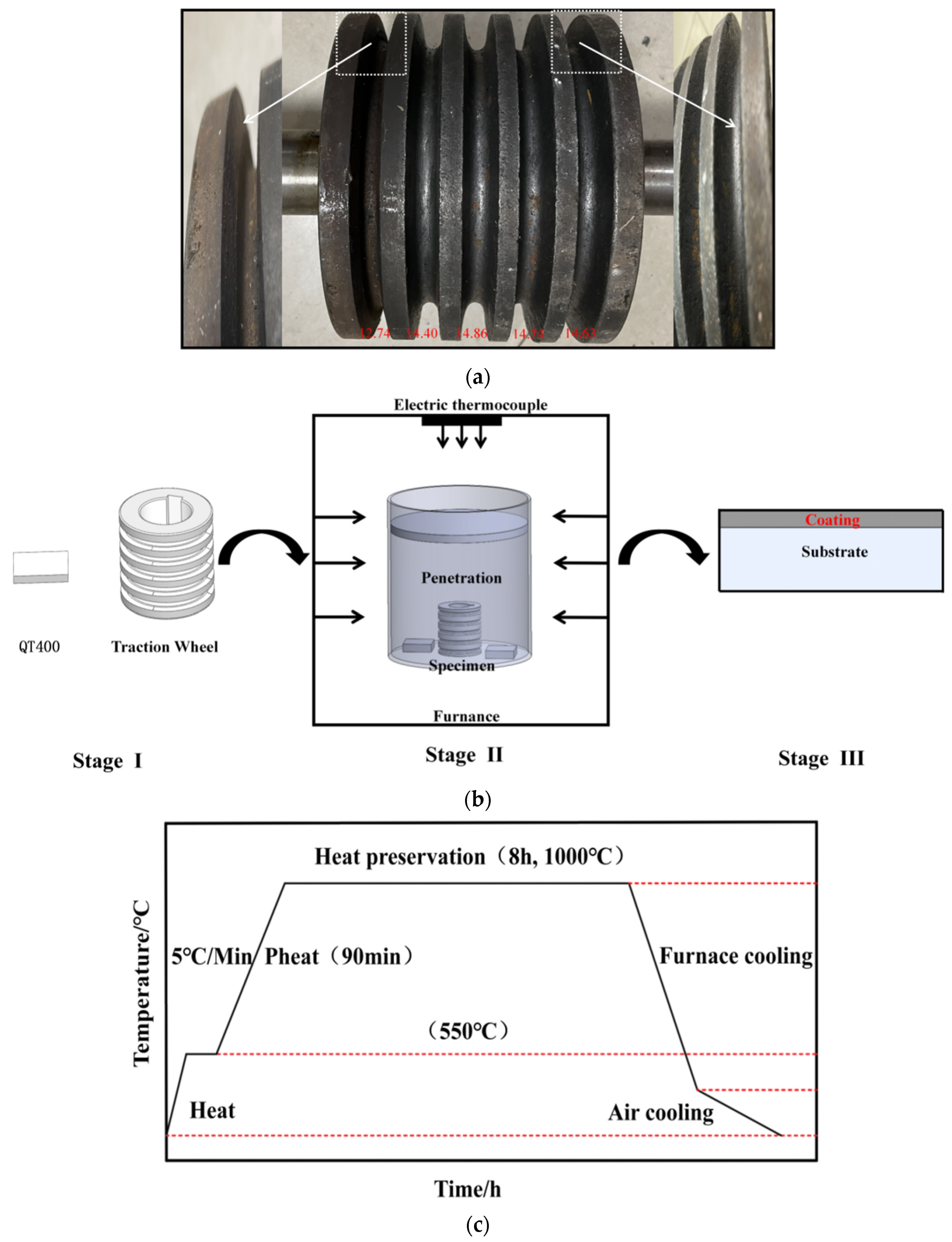
2.1. Experimental Material

QT400 traction-wheel samples were used in this study. The composition of QT400 was as follows: C, 3.45%~3.64%; Si, 2.47%~3.02%; Mn, 0.45%~0.57%; S, 0.012%~0.026%; P, 0.047%~0.060%; Mg, 0.029%~0.062%; Re, 0.032%~0.047%. Figure 1b shows a schematic diagram of the thermal-diffusion chromizing process. Samples with a gauge dimension of 10 mm × 10 mm × 5 mm were prepared for chromizing. Prior to chromizing, all samples were polished with SiC abrasive paper to ensure good surface conditions. Then, samples were ultrasonically cleaned with acetone and anhydrous ethanol for 30 min and blow-dried for later use. Afterwards, the traction-wheel samples were coated with a chromizing agent and placed in a chromizing tank, which was sealed with water glass and refractory mud. Finally, the tank was placed in a non-standard box resistance furnace (JQF1100-40; Macro lang, Zhengzhou, China). The chromizing agent was composed of 12% high-carbon ferro-chrome powder (chromium supplier), 2% NH4Cl (activator), and 86% Al2O3 (filler). Figure 1c shows the processing technology of the thermal-diffusion chromizing process. After the process was concluded, the traction-wheel samples were cleaned both with anhydrous ethanol and ultrasonically to remove the residual chromizing agent from the surface and were blow-dried prior to the experiments.

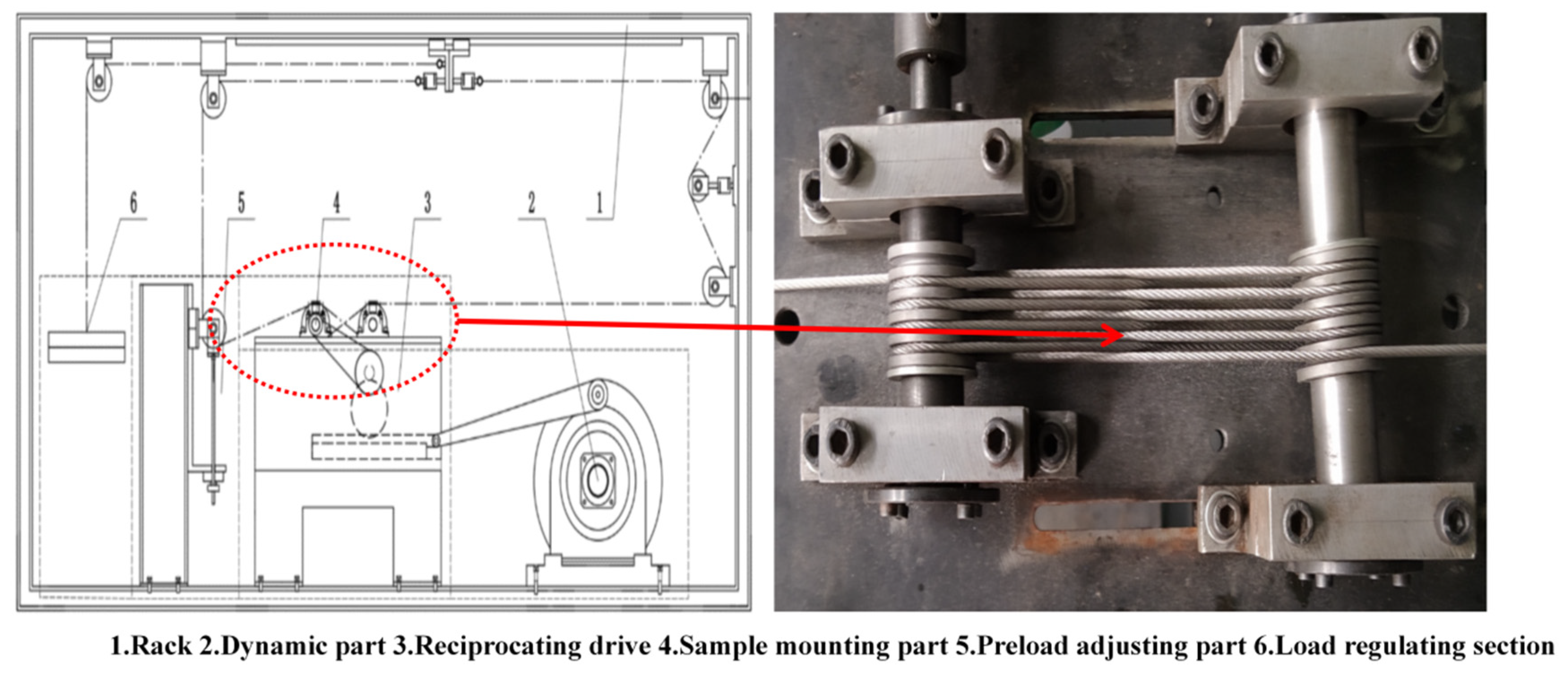
2.2. Experimental Method

Each sample’s surface was inlaid, ground, and polished, and the section was corroded. The surface morphology of the chrome coating was observed with a SEM system (FEI Sirion IMP; FEI, Hillsboro, OR, USA). X-ray diffraction (Bruker-axs D8; Bruker, Karlsruhe, Germany) was used to obtain the phase structure of the chromium carbide samples. The scanning angle range was from 20° to 90°. The distribution and proportion of element composition in the chrome coating was determined via energy-dispersive spectroscopy (EDS; EDAX genesis 7000 EDS system; Philadelphia, PA, USA). Nanoindentation tests were performed using a nanoindentation tester (Agilent Nano Indenter G200; Agilent Technologies, San Francisco, CA, USA) to measure the surface mechanical properties of the samples (hardness and Young’s modulus) to determine the ability of the coating to resist deformation. The indentation depth was 2000 nm, obtained with a load from 0 to 900 mN applied for 300 s. Hardness was measured using a microhardness tester (HUA YIN; HV1000B; Lanzhou, China), and the load of the microhardness test was 2.1 N with a holding time of 15 s. An ultra-depth-of-field optical microscope (OM; Keyence VHX-6000; Keyence, Osaka, Japan) was used for 3D reconstruction in the roughness analyses. In the scratch test (Rtec MFT-5000; Rtec, San Francisco, CA, USA), linearly increased loads of 0–120 N were used; the sliding speed was 5 mm/min, and the scratch length was 5 mm.
The frictional test was performed using a tester (Rtec MFT-5000; Rtec, San Francisco, CA, USA) under a load of 60 N for 20 min at a frequency of 5 Hz, with a reciprocating sliding distance of 5 mm, and 316 stainless steel was chosen as the mating material. Then, the wear simulation test of the traction wheel in a self-made orchard transport bench was conducted under dry and lubrication conditions. The wear simulation test in the bench was conducted with the following parameters: preload of 80 N, wheel–center distance of 720 mm, normal load of 120 N, 10 wheel turns, and running time of 8 h. Finally, the wear loss and wear morphology of the traction wheel in each group were compared, and the wear conditions of the corresponding wire rope and traction-wheel groove were observed with a super-depth-of-field microscope.

3. Results

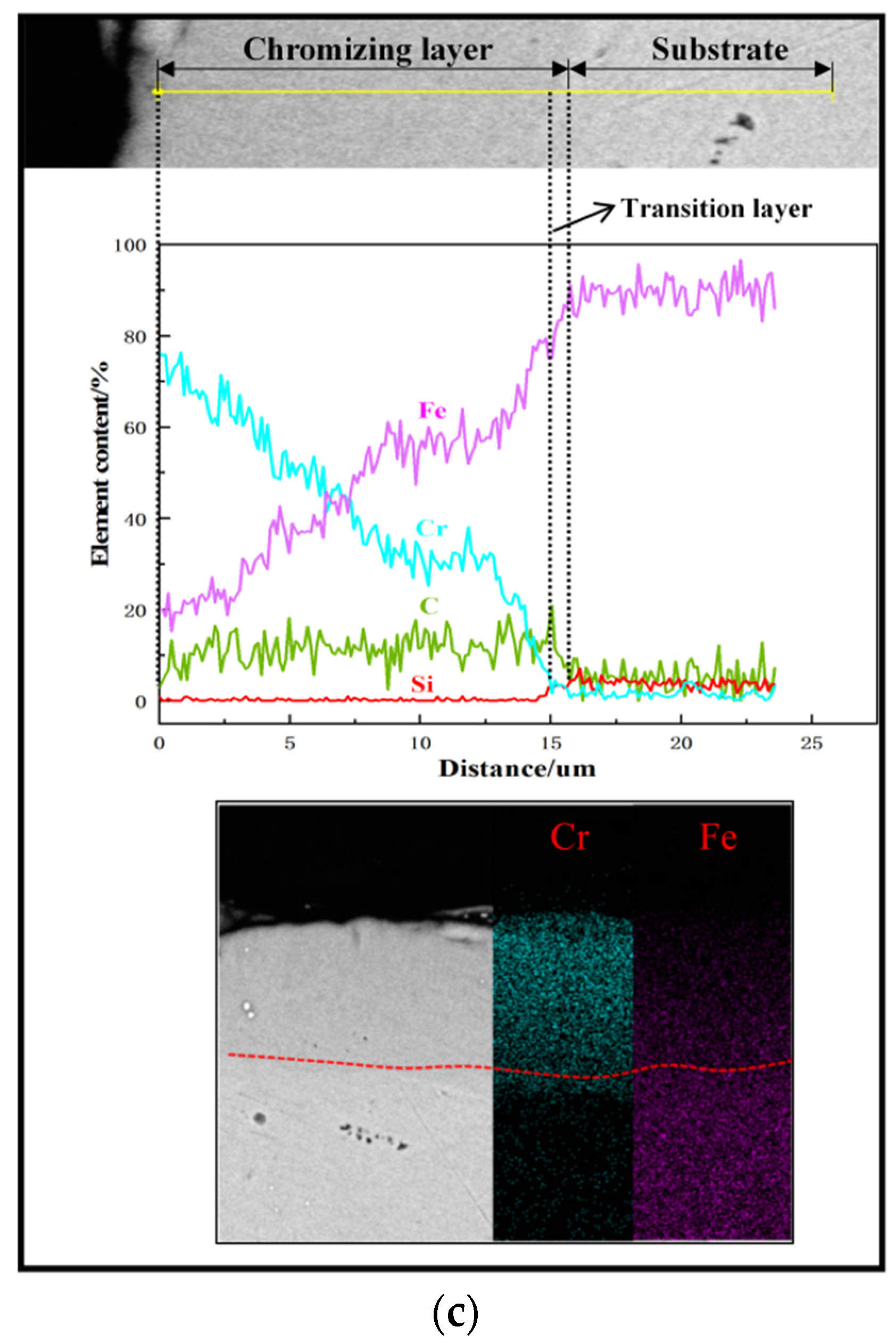
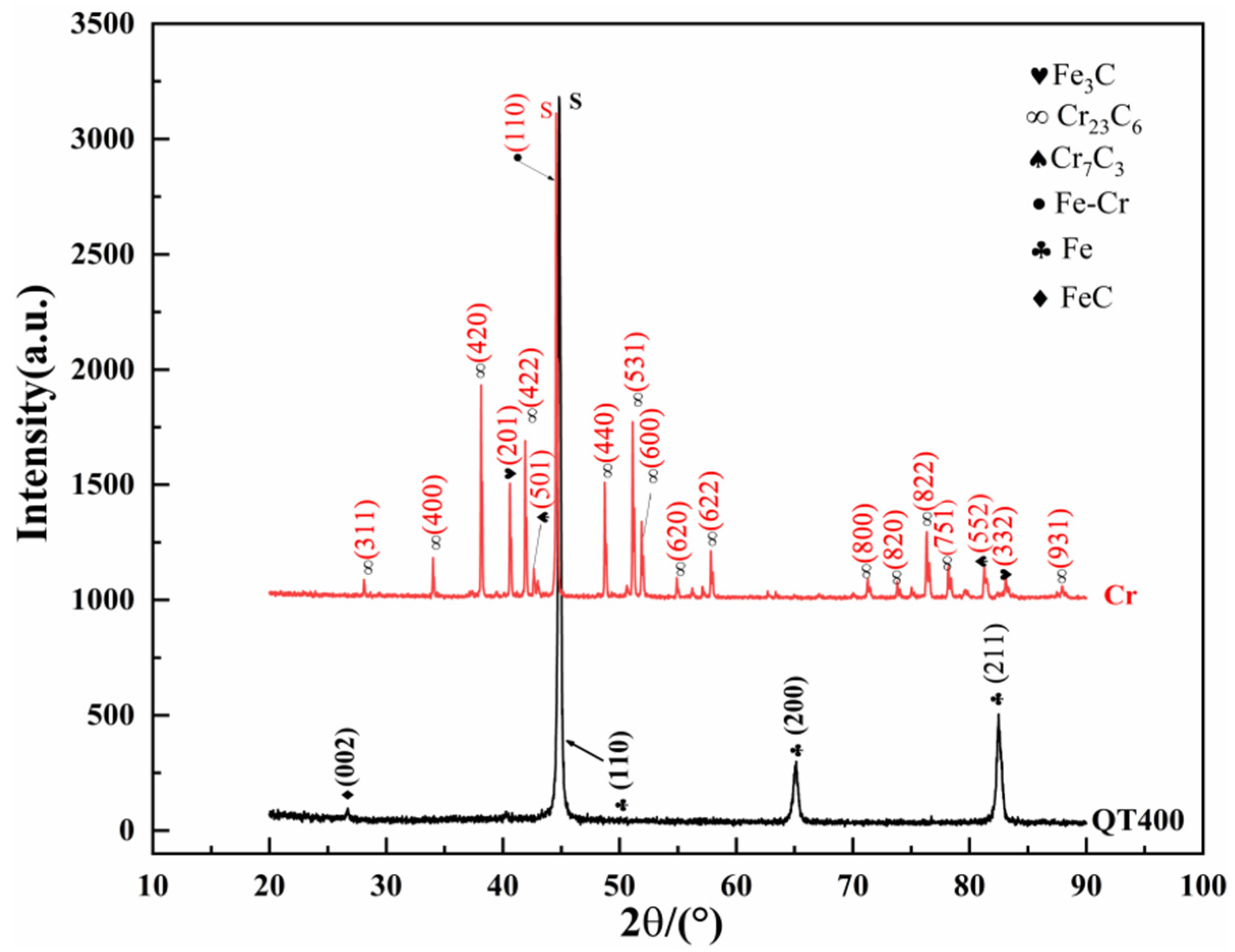
3.1. Microstructure of Chrome Coating

As shown in Figure 2a, the surfaces of the chromed samples revealed some granular protuberances with minor pores. The observed protuberances were reported to be chromium carbides. The pores on the coating surface were mainly caused by the migration, diffusion, and aggregation of vacancies, which formed via the diffusion of chromizing atoms to the QT400 substrate and the decomposition of gas atoms [27]. Figure 2b shows the cross-section structure morphology of a chromed sample. The interface was not uniform, which indicated good bonding between the top layer and the substrate. To further confirm the permeability of the layer, line scanning and element mapping were applied across the interface. As shown in Figure 2c, the top layer revealed high chromium contents, while the inner part presented higher Fe levels, which suggested that the top layer was a chrome permeable coating. The EDS line-scanning results suggested that the content of Cr slowly decreased from the top surface to the substrate, while that of Fe increased two-fold, indicating that the chrome coating formed via the inner diffusion of chromium and the outer diffusion of Fe. The maximum diffusion depth of the chromium was 16 μm. This also corresponded to the cross-section of the coating, as shown in Figure 2b. A certain thickness of the chromed layer was expected to provide excellent wear resistance to achieve longer service life. Moreover, as shown in Figure 2c, there was a transition layer between the chrome coating and the substrate, because the diffusion depth of C was larger than that of Cr. The transition layer with a higher ratio of C possessed greater hardness, as it formed large amounts of Fe-C compounds, and greatly increased the compatible deformation capability of the coating of QT400.
In order to further investigate the phase transition after chromizing, the XRD patterns of the chromed samples and of QT400 were compared, as shown in Figure 3. The chrome coating revealed many new characteristic peaks compared with QT400. These peaks corresponded to the Cr23C6, Cr7C3, Fe-Cr, and (Cr, Fe)7C3 phases [28]. The formation of carbides benefited from the large amount of C brought by chromizing, as revealed by the line-scanning results in Figure 2c. These carbons preferentially combined with Cr to form chromium carbides and then reacted with Fe to form ferrite carbides. Additionally, many Cr atoms penetrated into the original Fe lattice and formed an Fe-Cr solid solution because of the similar diameters of Fe and Cr atoms. Some of the C atoms dissolved into the Fe-Cr solid solution, while the other part formed a (Cr, Fe) carbide phase with a more complex structure. Chromium carbides and (Cr, Fe) carbides were expected to achieve precipitation strengthening in QT400 to increase the hardness to oppose wear.
To quantify the chromizing in terms of surface morphology, the surface-roughness value that could significantly affect the friction behavior was measured, as shown in Figure 4. The average surface roughness of the original QT400 sample was 1.074 μm and increased to 1.326 μm after chromizing. In addition, the measured Rz of the chrome coating was also higher than that of QT400. The increased surface roughness was attributed to the observed pores and protuberances.

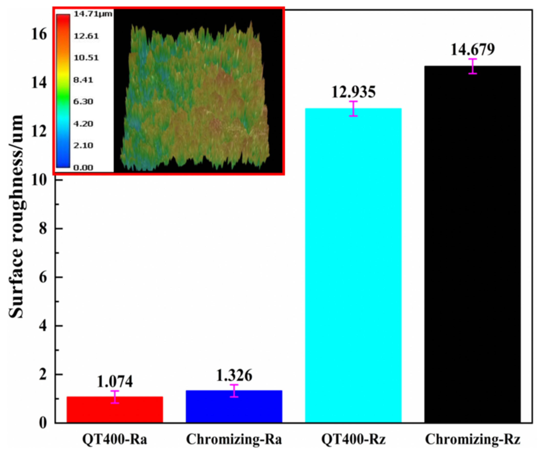
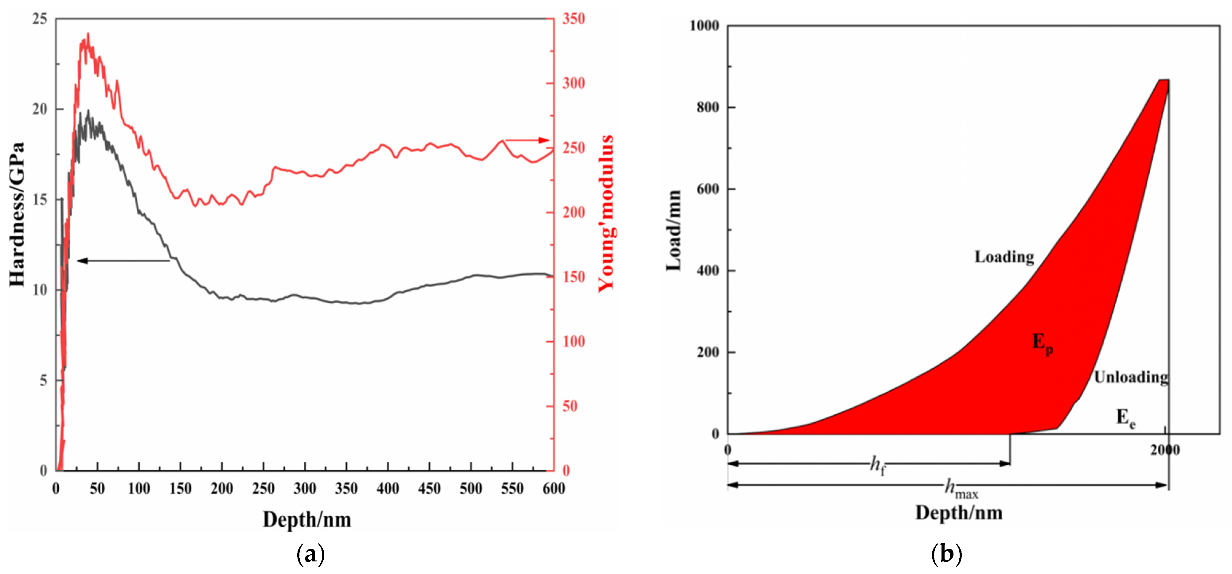
3.2. Mechanical Properties of Chrome Coatings

Hardness and roughness are key mechanical properties for components in terms of opposing wear. To characterize the mechanical properties of the coating, continuous stiffness measurements and scratch tests were used to measure the nanohardness (H), the elastic modulus (E), and the critical load required to crack the chrome coatings. The nanoindentation curve presents the values of H and E as functions of the indentation depth, as shown in Figure 5. The measured nanohardness and elastic modulus of the chrome coatings were 18.93 ± 0.35 and 320.98 ± 8.24 GPa, which is in agreement with other reports [29]. The measured hardness was further verified with the determination of a microhardness of 1752.7 HV. In order to evaluate the plastic-deformation resistance of the materials, it was necessary to obtain the deformation energy and the recovery ability. These behaviors can be described using the energy dissipation coefficient and the elastic recovery ability index, respectively. Formulas (1) and (2) are as follows:
K d = E p E p + E e
W e = H max H f H max
where Ep and Ee are the plastic-deformation energy and the elastic-deformation energy of the coating, respectively, and Hmax and Hf are the unloading depth and the elastic maximum penetration of the coating, respectively. The Kd of the chrome coating was 0.68, which is lower than the reported values for vanadium coatings and boron coatings. However, the calculated We of 0.355 is higher than that of vanadium coatings and boron coatings. The results suggest that the chrome coating had better elastic recovery ability and resistance to plastic deformation.
As reported in the literature, the failure of a coating during the scratch test is composed of two stages: the first stage involves the initiation of a crack on the modified surface layer due to the accumulation of internal stress; the second stage involves crack propagation, which leads to the spallation of the coating inside at the interface. The force that causes exfoliation between interfaces in the second stage is usually called adhesion. The critical loads for crack initiation and coating exfoliation are indicators of coating roughness and adhesion, respectively, which are the primary requirements for coating durability, and they can be detected using the scratch test [30]. Figure 6 shows the morphology of the scratches, the acoustic-emission curve, the friction curve, the friction-coefficient curve, and the loading-force curve of the scratch test. About 1277 μm from the initial scratch point, a high peak of the acoustic signal appeared, indicating a significant change in the coating under scratch stress. Accordingly, the friction coefficient also increased starting from this location. To explore the reason for the significant increases in the acoustic signal and friction coefficient, a SEM equipped with an EDS was employed to assess the morphology of the scratch. The SEM images revealed an obvious crack, as well as coating collapse around the scratch. These collapse areas, as well as the white areas in the scratches, were identified thanks to the identification of the substrate with Fe achieved using EDS mapping profiles. This indicated that the chrome coatings dually failed under scratch stress. The critical load was calculated to be 23 N. It needs to be noted that the initial crack was not observed. In an actual situation, fine binding strengthening usually requires the adhesion force of the coating to reach 20 N; this way, chrome coatings can meet the application requirements of actual sliding-wear conditions.

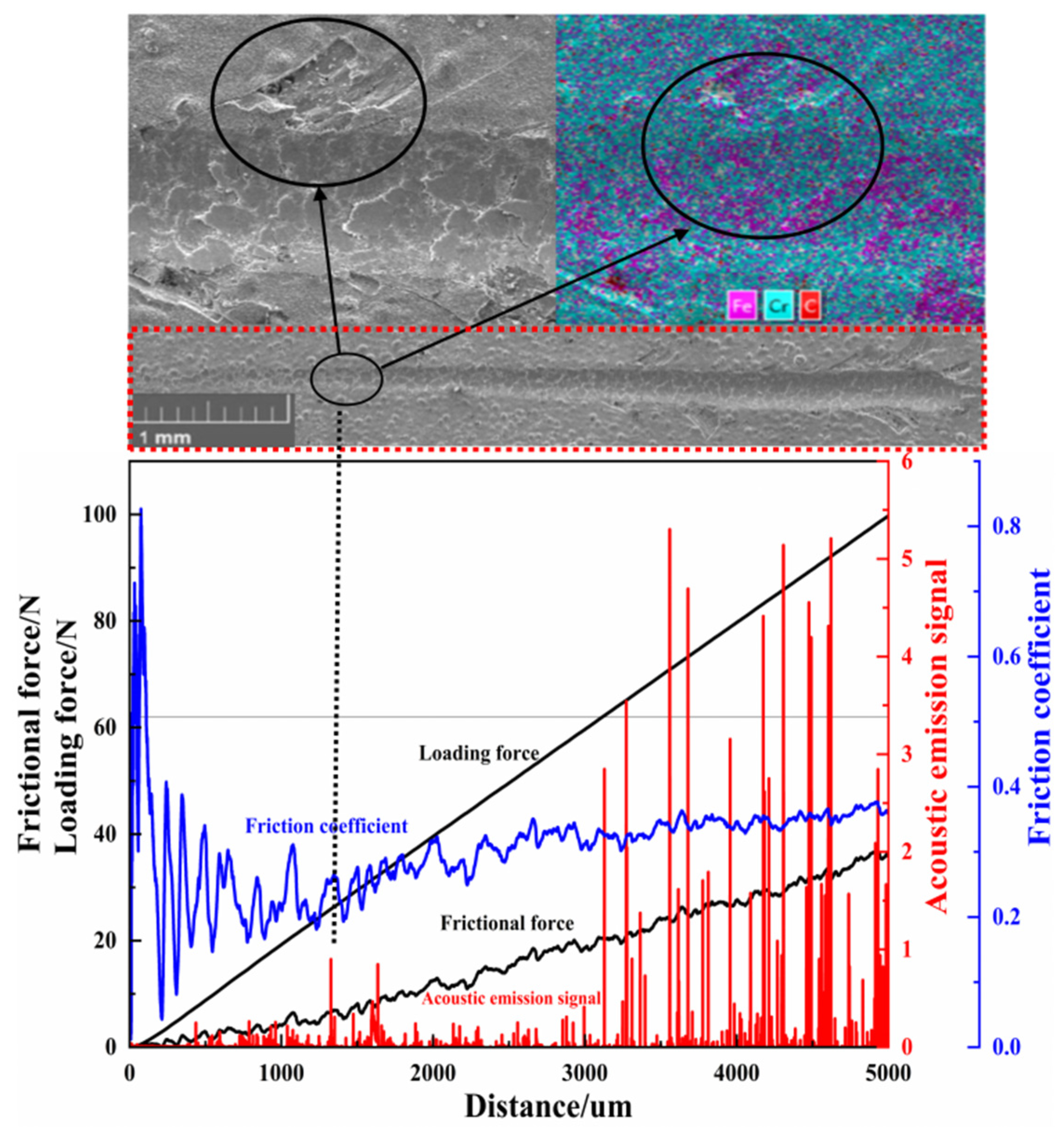
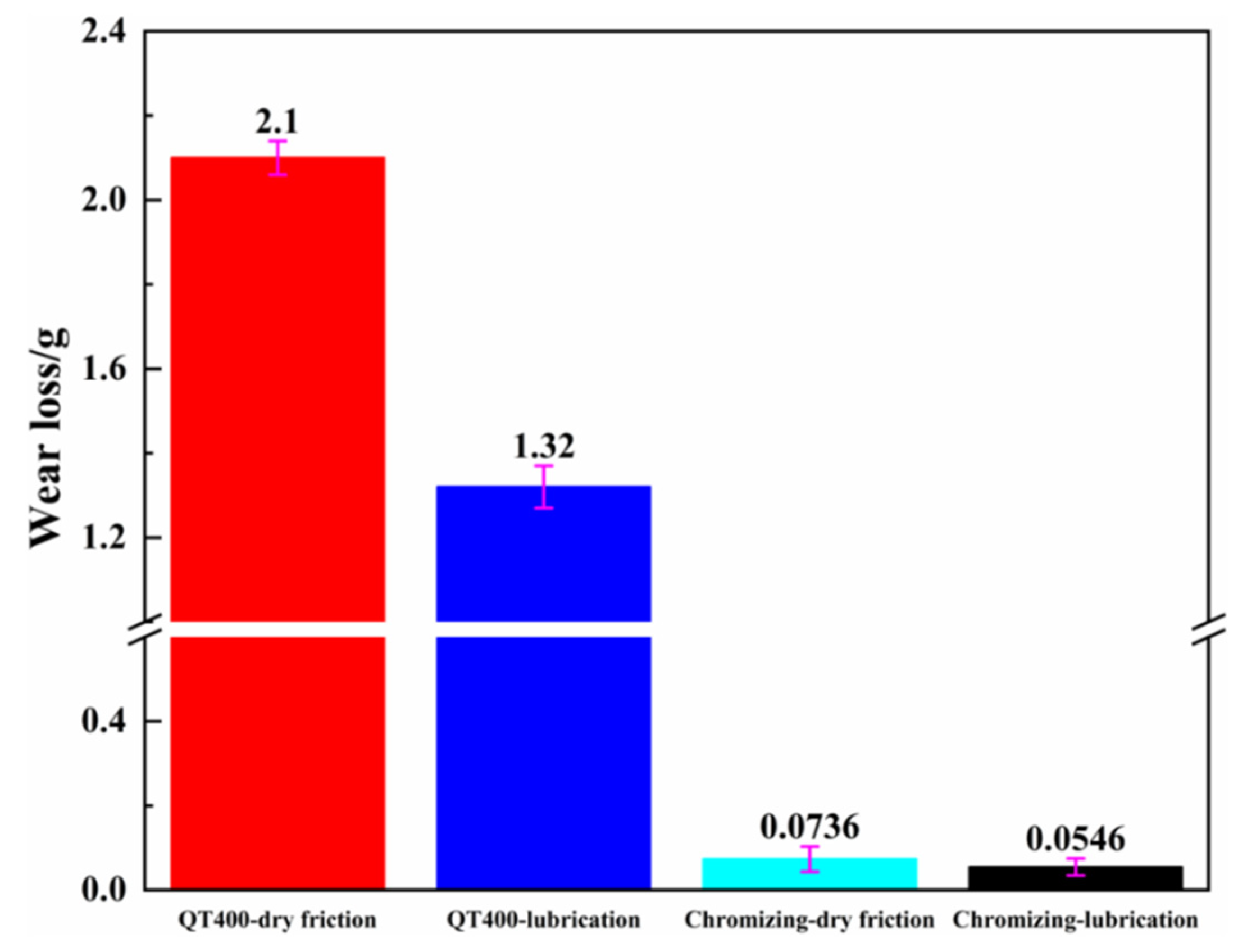
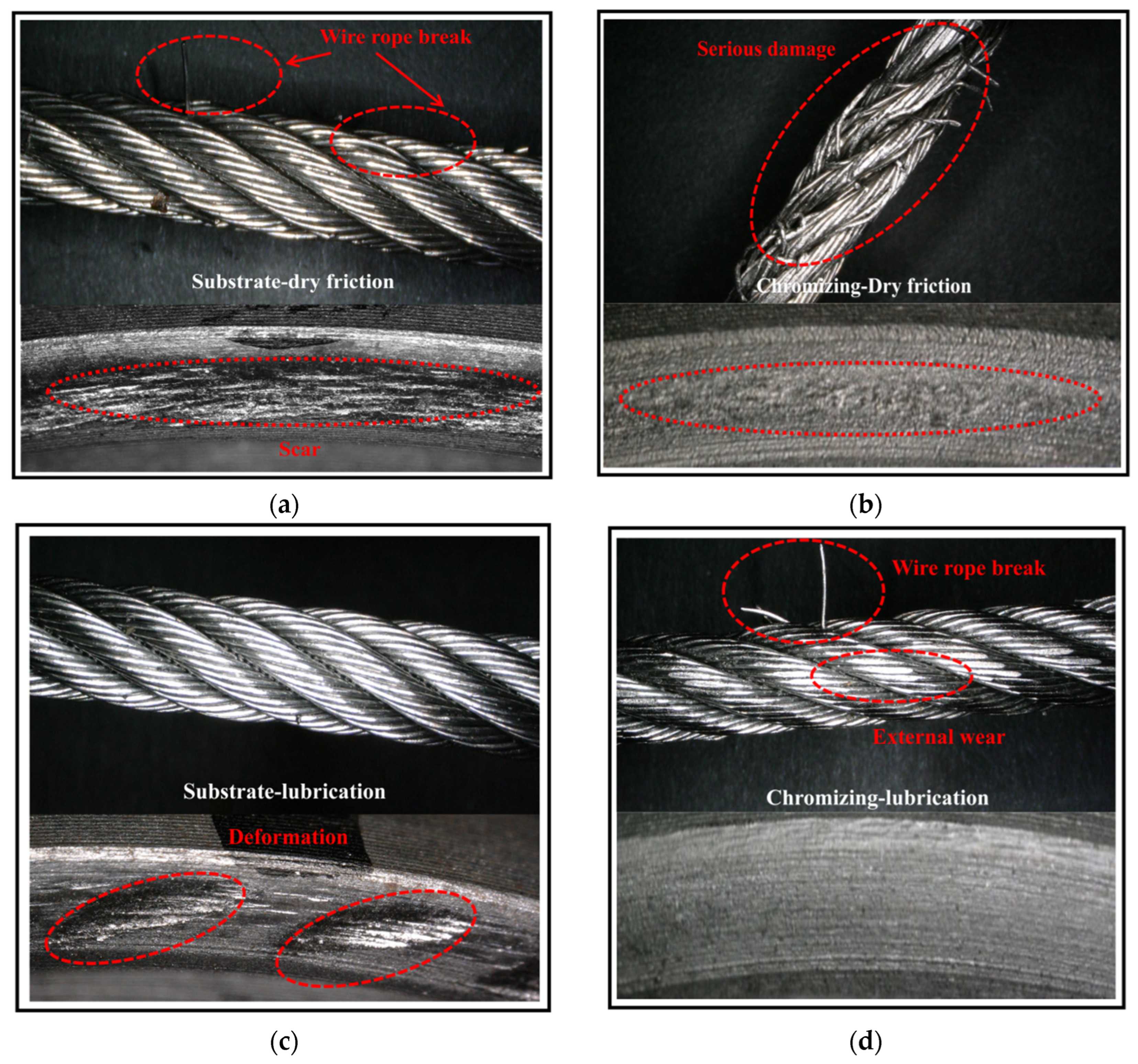
3.3. Friction Properties and Wear Resistance

To explore the wear behavior of the chromed samples, a sliding-friction test with the same stress as that between the rope and the wheel groove during service and a wear simulation test were carried out as explained in this section. The load for the sliding-friction test was calculated as shown below.
As shown in Figure 7a, the wire rope was simplified as a cylinder that made contact with both sides of the groove wall. Support forces dFN1 and dFN2 were perpendicular to both sides of the groove wall at the contact points and intersected at the center of the wire rope:
d F N 1 cos ( 15 ° ) = d F N 2 cos ( 15 ° )
d F N 1 sin 15 ° + d F N 2 sin 15 ° = d F N
where dFN1 and dFN2 are the support forces on the left side and the right side of the groove wall in the microsegment, respectively, and dFN is the total force of dFN1 and dFN2. As a brief formulation, dFN1 and dFN2 can be described as follows:
d F N 1 = d F N 2 = d F N 2 sin 15 °
A small section of the wire rope with angle dα was selected to analyze the force, as shown in Figure 7b. When the friction and centrifugal force were negligible, it could be considered that tension F0 had the same value at any position on the wire rope and that the tension was in the direction of the tangent line of the central axis of the wire rope. Contact pressure FN between the wire rope and the wheel was always along the normal direction of the arc surface of the pulley groove. Thus, the force analysis of the rope could be described using Formulas (6) and (7):
d F N = F 0 sin d α 2 + F 0 sin d α 2 + d F 0
F 0 cos d α 2 = F 0 cos d α 2 + d F 0 cos d α 2
where F0 is the preload, and dα is the corresponding wrapping angle of the mounted wire rope. Simplifying Formulas (6) and (7), we obtain:
d F N = 2 F 0 sin d α 2
According to Formula (8), contact pressure FN between the wire rope and the wheel was uniformly distributed along the circumference of the wheel. Because the value of dα was very small, sin d α 2 = d α 2 . Thus, the total normal force could be deduced from Formula (9):
d F N = 2 F 0 sin d α 2 = 0 α F 0 d θ = F 0 α
Similarly, the total force of FN1 could be deduced by substituting Formula (9) into (5):
F N 1 = 0 α 0 F 0 d α 2 sin ( 15 ° ) = F 0 α 0 2 sin ( 15 ° )
As shown in Figure 7c, the average pressure (Fp) at each contact position between the rope and the wheel in a single groove can be described as:
F p = P w F N 1 L N = P w F 0 α 0 2 L N sin ( 15 ° )
where L is the length of the single-loop wire rope, Pw is the lay length, and N is the number of external strands of the wire rope. According to Formula (11), the parameters of the wire rope are listed in Table 1. During the operation of the conveyor, the loaded F0 was 3000 N. Therefore, the average normal force between the wire rope and the wheel was calculated to be 60 N according to Formula (11), which provided a reference axial load for the subsequent friction test.
The friction behavior between the rope and the groove was simulated with a ball–disc sliding test by applying the load calculated above. Figure 8b exhibits the friction curves for QT400 and the chrome coating in dry and lubricated environments. The friction curves obtained under dry conditions presented a running-in stage and a stable-friction stage. The running-in stage revealed increased COFs because of the two-fold increased contact area [31,32]. In the stable-friction stage, the COFs of the chrome coating and QT400 were 0.37 and 0.38, which were achieved in 200 and 1000 s, respectively. This suggested that the chromed samples reached the stable stage quicker than QT400 alone. In addition, the COF of QT400 still varied in the stable stage and became two times larger than that of the chrome coating after 1000 s, indicating the varied surface roughness of QT400 during sliding, which may have resulted from debris and deformation. With the addition of oil for lubrication, the COF of QT400 greatly decreased, to 0.12, while that of the chrome coating remained similar, with a value of 0.35. It was suggested that the bearing capacity of the traction-wheel–rope system relied on the friction between the rope and the wheel. Therefore, the application of lubricating oil was suitable for the chrome coating but not for QT400 because of the sacrificed bearing capacity. Additionally, the morphology of the wear scar was observed using an ultra-depth-of-field microscope, as shown in Figure 8c. Under dry-friction conditions, substrate wear was significant under the impact of the grinding ball, and with the increase in wear depth, many cracks appeared on the surface. In contrast, the chrome coating had a wide surface and shallow depth, and wear was not as obvious. Mainly due to its great hardness and toughness, the bearing capacity was increased [33]. Under the impact of the grinding ball, the deep plastic deformation did not significantly change, so the wear scar was shallow and the substrate was effectively protected. Under lubrication conditions, the wear scars of the substrate and coating were reduced, indicating that lubrication could alleviate wear.
The wear resistances of wheels made with QT400 and those of surface-chromed wheels were verified using a self-made bench tester, as shown in Figure 9. Generally, the speed between the wire rope and the traction wheel changes during machine operation, leading to the wear of the traction wheel. To compare the wear resistance of these two wheels during service, a wear simulation test was carried out under dry and lubrication conditions. Then, the wear loss and morphology of the traction wheels in each group were investigated, and the morphology of the corresponding wire ropes was also observed to confirm the performance of the modified wheel–rope system.
Figure 10 shows the wear loss of two different traction wheels obtained by performing the bench test under dry and lubrication conditions. Under dry conditions, the wear loss of the chromed traction wheel was 0.0736 g, which was about 1/28 of that of the QT400 traction wheel. Under lubrication conditions, the wear loss of the chromed traction wheel was about 1/24 of that of the QT400 traction wheel. As a result, it was noted that the wear loss of the chromed wheel was much lower than that of the QT400 wheel under dry and lubrication conditions, indicating significantly enhanced wear resistance. The reduction in the wear loss of the chromed wheel compared with the QT400 wheel could be attributed to the enhancement in the surface hardness of the wheel.
Figure 11 shows the wear morphology of the groove and that of the wire rope after the bench test. Under dry conditions, a long, deep scar was observed in the QT400-traction-wheel groove, as shown in Figure 11a. As for the chromed wheel, no obvious pits were observed on the surface, and the scar was much shallower than that on the QT400 wheel. The relatively shallower scar on the chromed wheel could have resulted from the higher hardness of the chrome surface coating [34]. With the addition of oil, several pits were observed on the QT400 sample, and no obvious surface damage was observed on the chromed wheel, suggesting that lubrication could effectively alleviate the wear of the wheel. In addition to the morphology of the wheel, the morphology of the rope was analyzed. The results suggest that the rope would have broken and that the damage would have worsened, had the hardness of the wheel increased, as more break lines were observed in the rope that was tested with the chromed wheel. Fortunately, the break line could be reduced with the addition of oil, as shown in Figure 11d.

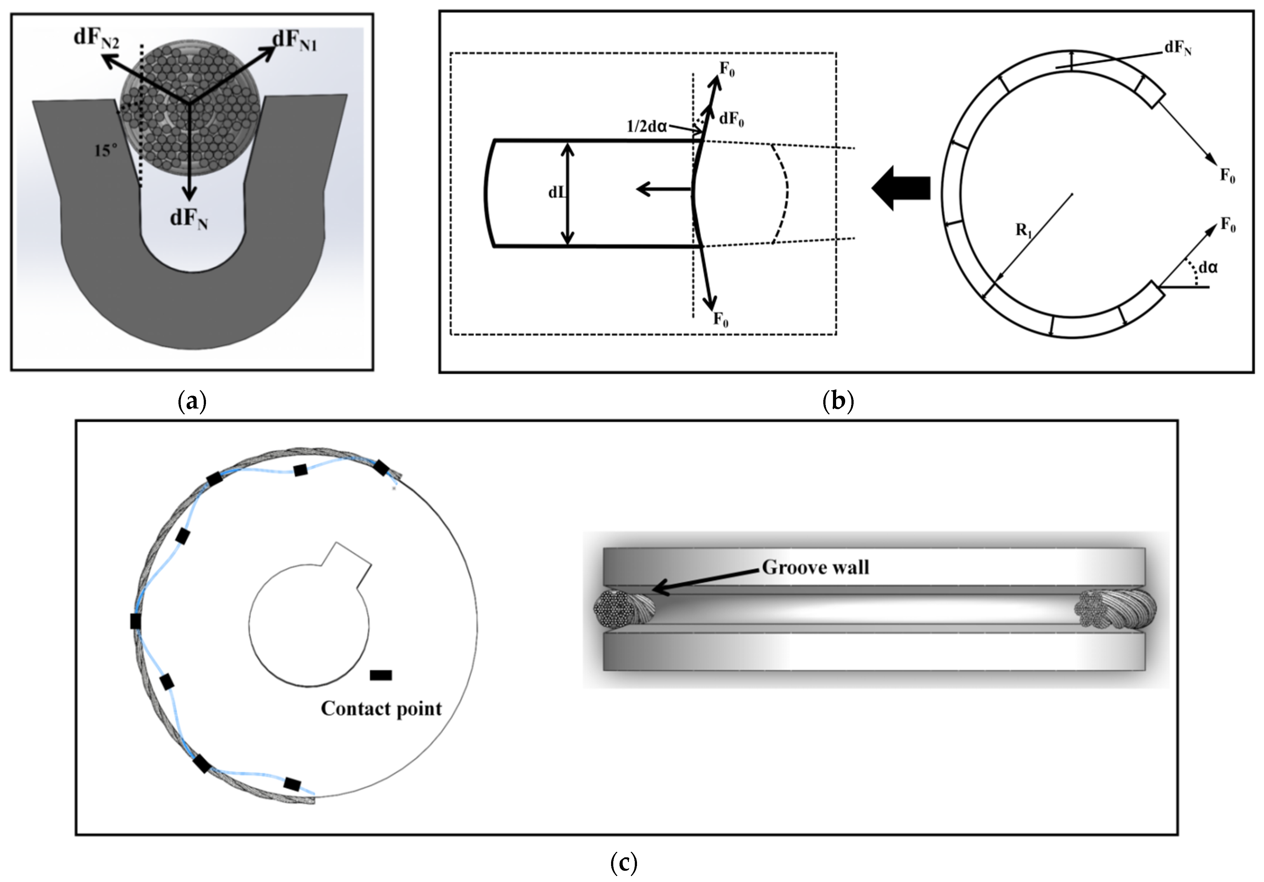
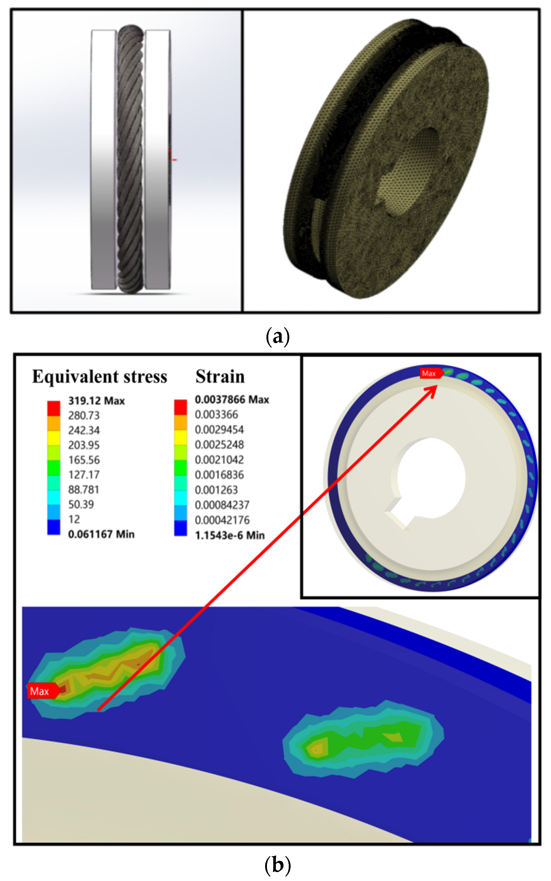
3.4. Mechanism of Enhanced Wear-Resistance Based on FEA
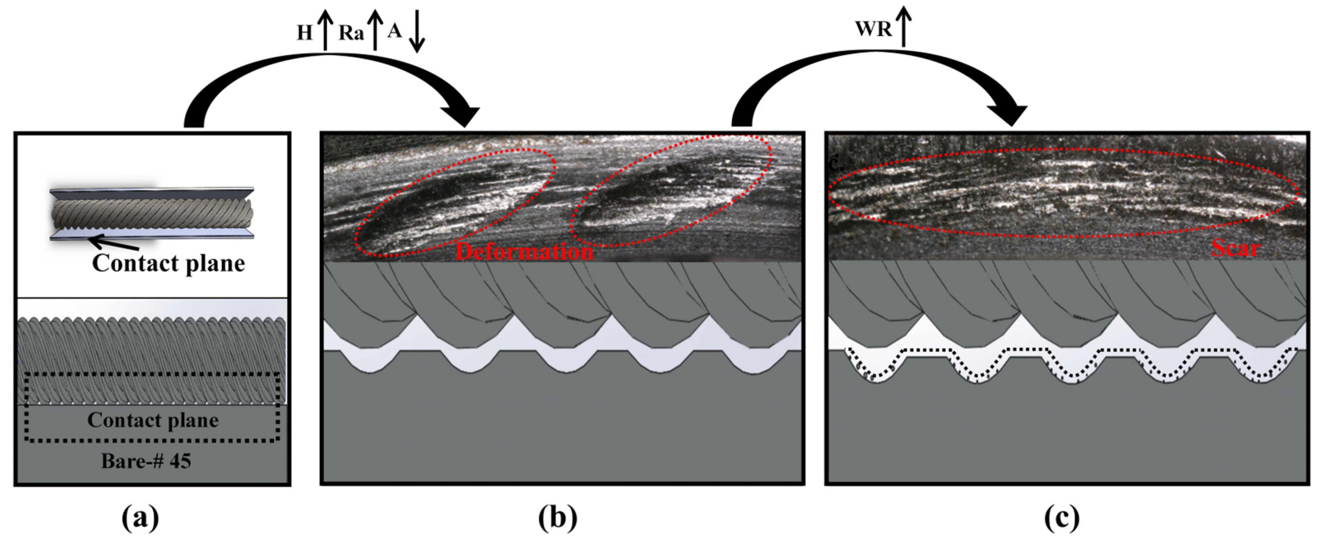
Based on the above results, the chromed wheel presented better wear resistance, showing less wear loss and lighter surface damage. The reason behind these results was proposed to be the high hardness selected. However, how hardness affects the wear between the rope and the wheel is still unknown. In order to establish the mechanism of the enhanced wear resistance of the chromed traction wheel in detail, the contact stress and later surface deformation were studied using FEA (finite element analysis) based on the real wheel–rope contact model [35]. The traction wheel and the wire rope were assembled in Solidworks to analyze traction-wheel wear under actual working conditions, as shown in Figure 12a. According to the actual contact between the wire rope and the traction wheel, the model was imported into Ansys finite element software, and the contact stress between the rope and the wheel was assessed. Table 2 lists the material parameters of the FEA of the wire rope and traction wheel. The mesh division of the rope–wheel model was simplified without affecting the solution results. The mesh sizes were set as 0.80 mm and 2.00 mm for the contact surface and non-contact area, respectively, in the finite element model. In total, the number of elements was 506,300, and the number of nodes was 609,937. Figure 12a shows the finite element model of the selected mesh. Due to the large number of contact pairs between the wheel and the rope, all contacts were defined as friction contact. We adopted the body interaction contact method to realize automatic contact. Then, combined with the actual working conditions, the boundary conditions were applied to the finite element model. A corresponding force was applied to both ends of the wire rope. Figure 12b reveals the contact and surface deformation of the wheel under the applied load. The contact areas between the rope and the wheel groove were many uniformly distributed small areas, which were also observed in the optical micrographs of the surface of the wheel after the wear simulation test, as shown in Figure 11. When the load was set as 1960 N, the maximum contact stress in the contact area was 319.12 MPa, which was higher than the yield strength of QT400, resulting in the obtained plastic deformation of the QT400 wheel groove.
According to the above discussion, the wear process of the wheel can be schematically described as shown in Figure 13. As the rope and wheel were assembled, the contact areas were many uniformly distributed small points [36,37,38]. Then, the load was applied between the rope and the wheel, representing the transportation of goods from the mountain base to the top. The applied load induced large stress, over 319 MPa, on the contact area, which resulted in obvious surface deformation, such as pits on the groove surface, as shown in Figure 13b. These pits greatly increased the surface roughness, and the contact stress increased with the decrease in the contact area, which greatly accelerated the wear process. The rope was quickly worn because of the generated stress and the uneven edge of the pits, as shown in Figure 11a. Regarding the wheel, the areas between pits were preferentially worn, forming a long scar on the wheel surface by linking these pits, as shown in Figure 13c. It could be concluded that the QT400 wheel’s process of wear was the continuous expansion of surface deformation, resulting in material shedding and the formation of pits. Therefore, the main wear mechanism of the QT400 traction wheel was fatigue wear. Meanwhile, in regard to the chromed traction wheel, because of the higher hardness, about 18.9 GPa, which was much greater than the yield strength of the wheel, contact stress rarely caused the deformation of the chromed surface. However, some small furrows and pits were roughly distributed on the chromed surface. When the wire rope was in the same direction as the furrow, plastic deformation formed plow wrinkles under the action of the plow [39,40]. Therefore, the main wear mechanism of the QT400 traction wheel was abrasive wear. Regarding the high COF induced by the high surface roughness, the wear behavior of the surface of the chromed traction wheel was rather mild. By comparing Figure 13c and f, it can be seen that the wear scar resulting from the friction between surface chromium carbides and the rope was quite shallow. Therefore, it is reasonable to conclude that the wear mechanism changed from fatigue wear to abrasive wear because the surface was modified with the TD chromizing method.

4. Discussion

Wear is the main failure mode of traction wheels in orchard transport; it greatly threatens the safe operation of orchard conveyors and impedes the development of the mechanization of orchards. Based on the observed morphology of the wear scars and the FEA results, the surface of the wheel revealed obvious pits, which were induced by high contact stress of 319.12 MPa. These pits greatly increased the surface roughness and led to accelerated wear at their edges. The accelerated effect greatly depended on the size of the pits, especially the depth, which was significantly related to the surface hardness of the wheel. Thermal-diffusion chromizing was employed to increase the surface hardness to enhance the wear resistance of the wheel. After chromizing, the surface hardness increased to 18.93 GPa, and the pits were much shallower than those on the QT400 wheel. The wear behavior of the chromed wheel was tested using a friction tester and a self-made wear simulation tester. The results obtained using both tests suggest that the chromed surface layer greatly decreased the wear loss, to almost 3%, by enhancing the surface hardness, confirming the above speculation. The underlying mechanism was investigated using the friction test to analyze the wear morphology and an FEA analysis to assess the stress and strain distribution. The synergetic effect between fatigue wear and abrasive wear was considered responsible for the wear failure of the traction wheel. It can be concluded that the enhanced surface hardness obtained via the chromizing method increased the wear resistance by reducing contact-stress-induced surface deformation and decreasing the abrasive wear process. The results suggest that chromizing treatment is a promising method to enhance the wear resistance of QT400 traction wheels without sacrificing the loading capacity. In addition, the research method combined the friction-wear test with an FEA stress analysis, thus providing a new strategy for the wear study of many machine components.

5. Conclusions

(1) A chrome coating of about 16 um was formed on the top surface of QT400 via thermal diffusion. The coating consisted of Cr23C6, Cr7C3, Fe-Cr, and (Cr, Fe)7C3, which hardened the surface, achieving a hardness of 18.93 GPa. The critical load for crack initiation in the chrome coating was 23 N, and the elastic recovery ability index was calculated to be 0.355, indicating a good elastic recovery ability for this chrome coating.
(2) In the sliding test against 316 stainless steel, the friction coefficients of QT400 and the chrome coating were 0.37 and 0.36, respectively. Then, the friction coefficient of QT400 decreased to 0.12, while that of the chrome coating remained similar, with a value of 0.35, under oil-induced lubrication conditions. This suggested that the application of lubricating oil did not significantly affect the bearing capacity of the chromed traction wheel.
(3) In the bench test, the wear losses of the chromed traction wheel under dry conditions and lubrication conditions were just 1/28 and 1/24 of those of the QT400 traction wheel, respectively, indicating obviously enhanced wear resistance. Oil lubrication could be applied to chromed wheels to reduce wear without sacrificing the bearing capacity.
(4) The fast wear rate of the QT400 wheel was attributed to the rapid surface deformation induced by a contact stress of about 319 MPa under a load of 1960 N. The chromed wheel with a hardness of over 18.93 GPa greatly alleviated surface deformation and presented enhanced wear resistance. Accordingly, the wear mechanism changed from fatigue wear to abrasive wear due to the employment of the TD chromizing method. The results suggest that the TD chromizing method is effective in prolonging the service life of traction wheels.

Author Contributions

Conceptualization, S.L. and Q.W.; data curation, Z.Y. and J.H.; formal analysis, Z.Y. and J.H.; methodology, Y.X., X.Z., R.G. and L.M.; project administration, S.L.; resources, S.L.; software, Z.Y. and Y.X.; supervision, J.H., X.Z., R.G. and L.M.; validation, S.L., Q.W. and Z.Y.; writing—original draft, S.L., Q.W. and Z.Y.; writing—review and editing, Q.W. and Z.Y. All authors have read and agreed to the published version of the manuscript.

Funding

This work was partially supported by the National Natural Science Foundation of China (11905082 and 51905204), Fundamental Research Funds for Central Universities (No. 2662020GXPY002), National Key R&D Program (2020YFD1000101), China Agriculture Research System of MOF and MARA (CARS-26), Construction Project of Citrus Whole Course Mechanized Scientific Research Base (Agricultural Development Facility (2017) 19), and the Hubei Agricultural Science and Technology Innovation Action Project.

Institutional Review Board Statement

Not applicable.

Informed Consent Statement

Not applicable.

Data Availability Statement

Not applicable.

Conflicts of Interest

The authors declare no conflict of interest.

References

  1. Li, S. Characteristics Analysis and Experimental Research on Driving Wheel Set of Self-Propelled Double-Track Orchard Transport. Ph.D. Thesis, Huazhong Agricultural University, Wuhan, China, 2012. [Google Scholar]
  2. Li, S.; Hou, J.; Wan, Q.; Qiao, A.; Li, W.; Xin, Z.; Liu, X.; Zhang, Z. Friction and wear of driving rope wheel of traction mountain orchard transport. Ransactions Chin. Soc. Agric. Eng. 2021, 37, 71–78. [Google Scholar]
  3. Pu, H. Theoretical Research and Life Estimation of Non-Rotating Wire Rope for Crane. Ph.D. Thesis, South China University of Technology, Guangzhou, China, 2012. [Google Scholar]
  4. Zhang, D.; Ge, S.; Qiang, Y. Research on the fatigue and fracture behavior due to the fretting wear of steel wire in hoisting rope. Wear 2003, 255, 1233–1237. [Google Scholar] [CrossRef]
  5. Xing, J. Design and Simulation of Self-Propelled Double-Track Orchard Transport with Large Slope. Master’s Thesis, Huazhong Agricultural University, Wuhan, China, 2012. [Google Scholar]
  6. Wang, D.; Zhang, D.; Wang, S.; Ge, S. Finite element analysis of hoisting rope and fretting wear evolution and fatigue life estimation of steel wires. Eng. Fail. Analy. 2013, 27, 173–193. [Google Scholar] [CrossRef]
  7. Chen, H.; Zhang, H.; Xu, W. Analysis of wear Causes of steel wire rope in mine Hoisting. Sur. Technol. 2009, 38, 85–86. [Google Scholar]
  8. Zhang, J.; Wang, D.; Zhang, D.; Ge, S.; Wang, D. Dynamic torsional characteristics of mine hoisting rope and its internal spiral components. Tribol. Int. 2017, 109, 182–191. [Google Scholar] [CrossRef]
  9. Zhou, Z.; Yuan, W.; Fang, T.; Fu, Q. High temperature wear resistance of cobalt-based cladding layer surfacing on H13 steel. Key Eng. Mater. 2019, 815, 81–88. [Google Scholar] [CrossRef]
  10. Hussein, M.; Adesina, A.; Kumar, M.; Sorour, A.A.; Al Aqeeli, N. Investigations of in vitro corrosion, and wear properties of TiN PVD coating on Ti6Al4V alloy for dental application. Key Eng. Mater. 2019, 813, 1–6. [Google Scholar] [CrossRef]
  11. Chen, K.; Wang, Y.; Wu, G.; Wang, M.; Zhang, Q.; Yao, J. Simulation and experimental study on temperature characteristics of laser quenching based on scanning galvanometer. Surf. Technol. 2020, 49, 262–269. [Google Scholar]
  12. Ma, C.; Hu, J.; Liu, Y. Research progress of Metal Infiltration technology on Materials surface. J. Chongqing Inst. Technol. 2016, 10, 70–75. [Google Scholar]
  13. Wan, Q.; Zhu, F.; Liu, X.; Wei, M.; Wang, S.; Meng, L.; Wang, P.; Dong, W. Microstructures and Properties of High-efficiency Egg-breaking Blade after boronizing and Vanadium vanadium treatment. Trans. Chin. Soc. Agric. Eng. 2020, 36, 291–297. [Google Scholar]
  14. Ganji, O.; Sajjadi, S.A.; Yang, Z.; Mirjalili, M.; Najari, M.R. On the formation and properties of chromium carbide and vanadium carbide coatings produced on W1 tool steel through thermal reactive diffusion (TRD). Ceram. Int. 2020, 46, 25320–25329. [Google Scholar] [CrossRef]
  15. Taktak, S.; Ulu, S. Wear behaviour of TRD carbide coatings at elevated temperatures. Ind. Lubr. Tribol. 2010, 62, 37–45. [Google Scholar] [CrossRef]
  16. Sen, U. Wear properties of niobium carbide coatings performed by pack method on AISI 1040 steel. Thin Solid Film. 2005, 483, 152–157. [Google Scholar] [CrossRef]
  17. Fan, X.; Yang, Z.; Zhang, C.; Zhang, Y.; Che, H. Evaluation of vanadium carbide coatings on AISI H13 obtained by thermo-reactive deposition/diffusion technique. Surf. Coat. 2010, 205, 641–646. [Google Scholar] [CrossRef]
  18. Günen, A.; Soylu, B.; Karakas, O. Titanium carbide coating to improve surface characteristic, wear and corrosion resistance of spheroidal graphite cast irons. Surf. Coat. 2022, 437, 279–293. [Google Scholar] [CrossRef]
  19. Najari, M.R.; Sajjadi, S.A.; Ganji, O. Microstructural evolution and wear properties of chromium carbide coating formed by thermo-reactive diffusion (TRD) process on a cold-work tool steel. Results Surf. Interfaces 2022, 8, 100059. [Google Scholar] [CrossRef]
  20. Su, X.; Zhao, S.; Hou, J.; Yu, G.; Chen, Y.; Sun, H.; Zhang, P.; Xie, L. Formation of chromium carbide coatings on HT250 steel by thermal diffusion processes in fluoride molten salt bath. Vacuum 2018, 155, 219–223. [Google Scholar] [CrossRef]
  21. Tan, C.; Zong, X.; Zhou, W.; Cao, H.; Wang, J.; Wang, C.; Peng, J.; Li, Y.; Li, H.; Wang, J.; et al. Insights into the microstructure characteristics, mechanical properties and tribological behaviour of gas-phase chromized coating on GCr15 bearing steel. Surf. Coat. 2022, 443, 215–233. [Google Scholar] [CrossRef]
  22. Fernandes, F.A.P.; Heck, S.C.; Picon, C.A.; Totten, G.E.; Casteletti, L.C. Wear and corrosion resistance of pack chromised carbon steel. Surf. Eng. 2012, 28, 313–317. [Google Scholar] [CrossRef]
  23. Kurt, B.; Kucuk, Y.; Sabri, G. Microabrasion wear behavior of VC and CrC coatings deposited by thermoreactive diffusion technique. Tribol. Trans. 2014, 57, 345–352. [Google Scholar] [CrossRef]
  24. Song, E. Experimental Study on TD Chromizing of Hot Working Die Materials. Master’s Thesis, Wuhan University of Technology, Wuhan, China, 2007. [Google Scholar]
  25. Zhao, X. Study on chromizing Mechanism of Low temperature Solid Powder. Master’s Thesis, Shandong University, Jinan, China, 2011. [Google Scholar]
  26. Song, B.; Wang, H.; Cui, W.; Liu, H.; Yang, T. Distributions of stress and deformation in a braided wire rope subjected to torsional loading. J. Strain Anal. Eng. Des. 2018, 54, 3–12. [Google Scholar] [CrossRef]
  27. Polcar, T.; Vitu, T.; Cvrcek, L.; Vyskocil, J.; Cavaleiro, A. Effects of carbon content on the high temperature friction and wear of chromium carbonitride coatings. Tribol. Int. 2010, 43, 1228–1233. [Google Scholar] [CrossRef]
  28. Zeng, J.; Hu, J.; Yang, X.; Xu, H.; Li, H.; Guo, N. Evolution of the microstructure and properties of pre-boronized coatings during pack-cementation chromizing. Coatings 2020, 10, 159. [Google Scholar] [CrossRef]
  29. Elhelaly, M.A.; El-Zomor, M.A.; Attia, M.S.; Youssef, A.O. Characterization and kinetics of chromium carbide coatings on AISI O2 tool steel performed by pack cementation. J. Mater. Eng. Perform. 2022, 31, 365–375. [Google Scholar] [CrossRef]
  30. Zawischa, M.; Makowski, S.; Kuczyk, M.; Weihnacht, V. Comparison of fracture properties of different amorphous carbon coatings using the scratch test and indentation failure method. Surf. Coat. 2022, 435, 128247. [Google Scholar] [CrossRef]
  31. Anand, M.; Burmistroviene, G.; Tudela, I.; Verbickas, R.; Lowman, G.; Zhang, Y. Tribological evaluation of soft metallic multilayer coatings for wear applications based on a multiple pass scratch test method. Wear 2017, 388, 39–46. [Google Scholar] [CrossRef]
  32. Mahdavi, A.; Medvedovski, E.; Leal Mendoza, G.; McDonald, A. Corrosion resistance of boronized, aluminized, and chromized thermal diffusion-coated steels in simulated high-temperature recovery boiler conditions. Coatings 2018, 8, 257. [Google Scholar] [CrossRef]
  33. Martinsen, M.; Hed, K.O.; Diget, J.S.; Lein, H.L. A novel approach for the evaluation of ice release performance of coatings using static friction measurements. J. Coat. Technol. Res. 2021, 18, 665–676. [Google Scholar] [CrossRef]
  34. Holmberg, K.; Laukkanen, A.; Ronkainen, H.; Waudby, R.; Stachowiak, G.; Wolski, M.; Podsiadlo, P.; Gee, M.; Nunn, J.; Gachot, G.; et al. Topography orientation effects on friction and wear in sliding DLC and steel contacts, part 3: Experiments under dry and lubricated conditions. Wear 2021, 486, 204093. [Google Scholar] [CrossRef]
  35. Emrani, A.; Berrada, A.; Bakhouya, M. Modeling and performance evaluation of the dynamic behavior of gravity energy storage with a wire rope hoisting system. J. Energy Storage 2021, 33, 102154. [Google Scholar] [CrossRef]
  36. Joseph, J.; Haghdadi, N.; Shamlaye, K.; Hodgson, P.; Barnett, M.; Fabijanic, D. The sliding wear behaviour of CoCrFeMnNi and AlxCoCrFeNi high entropy alloys at elevated temperatures—Science Direct. Wear 2019, 428, 32–44. [Google Scholar] [CrossRef]
  37. Wang, G.; Peng, Y.; Zhu, Z.; Wang, D.; Tang, W.; Chen, G.; Liu, W.; Zhang, Q.; Huang, K. Tribological properties and residual strength of wire rope with different strands during the interlayer-transition stage. Wear 2021, 480, 203930. [Google Scholar] [CrossRef]
  38. Randall, N.X. The current state-of-the-art in scratch testing of coated systems. Surf. Coat. 2019, 380, 125092. [Google Scholar] [CrossRef]
  39. Tsigkis, V.; Bashandeh, K.; Lan, P.; Polycarpou, A.A. Tribological behavior of PS400-related tribopairs for space exploration—ScienceDirect. Ribology Int. 2020, 153, 106636. [Google Scholar] [CrossRef]
  40. Wang, Q.; Rui, X.; Wang, Q.-J.; Bai, Y.; Du, Z.-Z.; Niu, W.-J.; Wang, W.; Wang, K.-S.; Gao, Y. Bonding and wear behaviors of supersonic plasma sprayed Fe-based coatings on Al-Si alloy substrate. Surf. Coat. 2019, 367, 288–301. [Google Scholar] [CrossRef]
Figure 1. Failed traction wheel and thermal-diffusion chromizing process. (a) Failed traction wheel. (b) Schematic diagram of the chromizing process. (c) Processing technology.
Coatings 12 01275 g001
Figure 2. SEM micrographs of chrome coating and chemical-composition distribution of the coating in cross-section. (a) Chromed coating surface (2000×). (b) Chromed layer (5000×). (c) Composition distribution of the sample in cross-section.
Coatings 12 01275 g002aCoatings 12 01275 g002b
Figure 3. X-ray diffraction patterns of chrome-coated and original QT400 samples.
Coatings 12 01275 g003
Figure 4. Surface roughness of QT400 and chromed samples.
Coatings 12 01275 g004
Figure 5. Nanoindentation test results of chrome coatings. (a) Hardness and elastic modulus of chrome coatings. (b) Nanoindentation curve illustration of mechanical parameters.
Coatings 12 01275 g005
Figure 6. Scratch analysis of the chrome coating.
Coatings 12 01275 g006
Figure 7. Force analysis diagram of wire rope when the microsegment was stationary. (a) Force analysis of wire rope and driving wheel. (b) Stress analysis of microsection wire rope. (c) Rope–wheel contact model.
Coatings 12 01275 g007
Figure 8. Comparison of friction coefficient between the chrome coating and QT400 under dry-friction and lubrication conditions. (a) Diagram of friction experiment. (b) Coefficient of friction curve. (c) Wear morphology.
Coatings 12 01275 g008
Figure 9. Self-made simulation bench.
Coatings 12 01275 g009
Figure 10. Wear loss of each sample under dry-friction and lubrication conditions.
Coatings 12 01275 g010
Figure 11. Wear morphology of the traction-wheel groove and wire rope under dry-friction and lubrication conditions. (a) Wear of rope–wheel with substrate only under dry-friction conditions. (b) Wear of rope–wheel with chromizing under dry-friction conditions. (c) Wear of rope–wheel with substrate only under lubrication conditions. (d) Wear of rope–wheel with chromizing under lubrication conditions.
Coatings 12 01275 g011
Figure 12. Contact stress and strain analysis of traction wheel. (a) Solidworks model of rope–wheel system. (b) Contact stress and strain analysis of traction wheel and wire rope.
Coatings 12 01275 g012
Figure 13. Wear mechanism analysis of traction wheel. (a) Substrate rope–wheel model. (b) Early wear stage of rope–wheel model. (c) Late wear stage of rope–wheel model. (d) Chromed rope–wheel model. (e) Early wear stage of chromed rope–wheel model. (f) Late wear stage of chromed rope–wheel model.
Coatings 12 01275 g013aCoatings 12 01275 g013b
Table 1. Parameters of wire rope.
ConstructionPW (mm)L (mm)Nα
8 × 19S + FC6.5130191.25π
Table 2. Material parameters of the traction wheel and wire rope.
MaterialElastic Modulus (GPa)Density (kg·m−3)Poisson’s Ratio
QT400 (traction wheel)18378500.3
316 stainless steel (rope)20078500.28
Publisher’s Note: MDPI stays neutral with regard to jurisdictional claims in published maps and institutional affiliations.

