Abstract
With rising energy demand and depleted traditional fuels, solar cells offer a sustainable and clean option. In recent years, and due to its acceptable band gap, high absorption coefficient, and inexpensive cost, iron pyrite (FeS2) is a popular material for solar cells. Earth abundance and nontoxicity further boost its photovoltaic possibilities. The current study examined the influence of sulfurization at 350–400 °C on iron pyrite layers fabricated using spray pyrolysis. The morphology and size from TEM confirmed the XRD results of synthesizing a pyrite FeS2 with an average particle size of 10–23 nm at 350–400 °C, respectively. The direct band gap calculated by DFT as a function of temperature was found to be consistent with the experimental findings, 0.87 eV (0.87) and 0.90 eV (0.95) at 350 °C and 400 °C, respectively. We found high-performing photovoltaic cells on ITO/ZnO/FeS2/ MoO3/Au/Ag, obtained with an excellent quality of nanoparticles and nanostructures of FeS2 pyrite, which improved with the method of preparation and growth parameters.
1. Introduction
In the last decades, transition metals experienced a renewal of interest due to their excellent electrical, transport, magnetic, and optical properties [1,2,3]. In general, pyrite is an ideal material for the fabrication of solar cells and photovoltaic devices [4,5,6,7,8,9] due to its high absorption coefficient [5], its small band gap (about 0.95 eV) [10], high photocurrent quantum efficiency () [6], and low material cost [4,5,6,7,8,9,10,11].
pyrite was one of the first crystal structures that resulted from Bragg, in 1914 [12], with his XRD system. It has a simple cubic structure similar to that of rock salt.
pyrite is a good option for thin film photovoltaic. Considering its potential and current importance [4,5,6,7,8,9], many experimental [4,5,6,7,8,9,13,14,15,16,17,18,19,20,21,22,23,24,25,26,27,28,29,30,31,32,33,34,35,36,37,38,39,40] and theoretical works [41,42,43,44,45,46,47,48,49,50,51,52,53,54,55,56,57,58,59,60] have been interested to. Schlegel et al. [33] determined the transition and reflectivity spectrum of a single crystal of . They showed that pyrite has an empty 3d eg band at 300 K, a completely filled 3 d t2g, and an indirect band gap equal to 0.95 eV. Kou et al. [25] found a band gap at 297 K of about 0.84 eV. Karguppikar et al. [40] reported that pyrite can be an indirect semiconductor from its conductivity properties, Hall effect data, and optical gap of 0.92 eV. Sun et al. [37] determined an pyrite thin film by sulfurizing oxide precursor films. From their UV-vis absorbance spectroscopy and X-ray photoelectron spectroscopy (XPS), they showed a direct band gap of about 0.75 eV, an indirect band gap of about 1.19 eV, and a high absorption efficiency (). Yu et al. [39] used the chemical bath deposition (CBD) method. They reported that the band gap of can be increased from 0.86 to 1.31 eV when doped by Mn.
Many other preparation methods, such as spray pyrolysis, metal organic chemical vapor deposition (MOCVD), and ion beam sputtering have been declared for the synthesis of nanocrystals, nanowires, and crystallites of .
Mostly all experiments found a band gap between 0.84 and 1.03 eV. For theoretical study, Bullet [42] used the first principle local density approximation (LDA) calculation to investigate the optical properties of iron pyrite. He found an indirect band gap of 0.4 eV for marcasite and 0.7 eV for pyrite. This value is smaller by 0.25 eV when compared to the experimental indirect band gap (0.95 eV). Zhoa et al. [59] performed the self-consistent linear combination of atomic orbital (LCAO) formalism to determine the electronic properties of iron pyrite. Their smallest theoretical direct band gap was about 0.64 eV, and they found an indirect band gap of 0.59 eV. Additionally, Opahlele et al. [53,54] determined the electronic properties of utilizing an LDA potential parameterized by the Perdew-Zunger (LDA-PZ). Their calculated band gap was about 0.85 eV. Muscat et al. [52] employed the periodic LCAO method with the CRYSTAL 98 package and pseudopotential technique with CASTEP Software package.
Wadia et al. [61,62] showed a complete research study a few years ago and investigated 23 potential materials for photovoltaics and found that pyrite was the best one, beating all materials in terms of cost. It was confirmed that the extraction cost of silicon was 57 times more than that of (USD 1.7 for silicon compared to USD 0.03 for ). Additionally, the silicon energy output for extractions was 12 times bigger than that of (24 KWh kg−1 vs. 2 KWh kg−1 for 24 KWh kg−1). Rahman et al. [62] showed that is much more cost-effective than silicon if they are produced with taxation and the same regulations in the same country. All these beneficial and interesting features make an excellent candidate for photovoltaic performance.
We included the prepared structure to show the real effect of the structure on band gap for devices that are not photovoltaic. The biggest dilemma for iron pyrite is attributed to the structure of pyrite, for which we complete studied to include the impact of the nanoparticles of iron pyrite on photovoltaic performance. This work aimed to improvise a new progress in the use of iron pyrite in photovoltaics.
2. Experimental
2.1. Materials and Method
We used spray pyrolysis for the fabrication of our sample. Amorphous iron oxide films were placed on normal glass substrates by spray pyrolysis. Then, the found films were heated under a sulphur atmosphere. We started by cleaning the glass substrates. The process was as follows: first, we put the films in an acidic solution for 3 h. After that, they were kept in a detergent solution and washed with distilled water. Then, they were kept in a solution of methanol and washed utilizing an ultrasonic cleaner for 15 min. Finally, the substrate was cleaned with distilled water and dried under a stream of nitrogen. In the second procedure, we chose to spray FeCl3·6H2O (0.05M) for 5 min in an aqueous-based solution onto glass substrates. After we dissolved FeCl3·6H2O in deionized water (ionization reaction: 2H2O H3O+ + OH−), a dark amorphous iron oxide layer was obtained. The jet flow rate and the distance nozzle-substrate were about 7 mL/min and 45 cm. Carrier gas was used by compressed air. We obtained dark layers. Then, it was heated under a sulphur atmosphere ( torr) at two sulfurization temperature (350 °C–400 °C). However, we succeeded in obtaining pyrite via spray pyrolysis.
2.2. Characterization
The crystal structure of the pyrite was analyzed by powder X-ray diffraction (XRD) using a Siemens D500 diffractometer (Siemens Bruker, Germany) (CuK radiation = 1.54201 ). The parameter lattice and crystal structure were obtained using the Reitveld method by utilizing the PDXL program. Raman spectra were determined to further study the phase evolution with increasing temperature. The morphology and size of nanocrystals were recorded using transmission electron microscopy (TEM) using JEOL 2010 (200 KV) microscopy. Optical absorption was investigated using a SHIMADZU 3100s spectrophotometer (SHIMADZU, Columbia, MD, USA).
2.2.1. X-ray Diffraction:
XRD patterns of the pyrite sample are shown in Figure 1. Typical diffraction peaks at 2 = 28.71°, 33.43°, 37.25°, 40°, 57.79°, 59.98°, 61.89°, and 64.31° are attributed respectively to plan (111), (200), (210), (211), (220), (311), (222), (230), and (321), corresponding with the norm diffraction data of the (JCPDS card n°028-0076; space group Pa3). No other impurities, such as marcasite, pyrrhotite, or greigite compounds, were detected in the XRD patterns, confirming the high purity of the obtained sample. Powder XRD patterns appeared in a cube of crystalline in a pyrite structure, where the disulfide ions localized in octahedral, coordinated with Fe metal ions within a space group symmetry of . The significant effect of temperature can be observed on the position of sulfur (S). The sulfur position changed when the temperature increased. The X-ray diffraction (XRD) patterns of two samples exhibit a notable degree of similarity, with minor discrepancies observed in the intensity of diffraction peaks. This resemblance is primarily attributed to the identical material composition of both samples, namely, iron pyrite. Moreover, it is imperative to note that the XRD patterns for these two samples share congruent structural characteristics, resulting in the consistent norm of diffraction data as specified in the ASTM file.
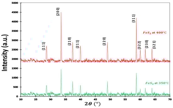
Figure 1.
XRD pattern of pyrite. The X-ray diffraction (XRD) patterns of two samples exhibit a notable degree of similarity, with minor discrepancies observed in the intensity of diffraction peaks. This resemblance is primarily attributed to the identical material composition of both samples, namely, iron pyrite. Moreover, it is imperative to note that the XRD patterns for these two samples share congruent structural characteristics, resulting in the consistent norm of diffraction data as specified in the ASTM file.
The output parameters are listed in Table 1.

Table 1.
Cells parameters.
2.2.2. Raman Spectra
The Raman spectra of the pyrite are presented in Figure 2. As shown, sulfurization was conducted at different times and temperatures (350 °C and 400 °C ). We identified that the increase of the sulfurization time and temperature reduced the perfection of formation of other phases, and this resulted in a pure pyrite structure. We observed two strong typical Raman peaks at 342 cm−1 and 403 cm−1, corresponding to Elow and EHigh modes and generated by Fe-Fe and S-S vibrations, respectively. We used long sulfurization times for two temperatures to find the growth condition for high throughput and low-cost processing. In the past literature, time sulfurization ranged between 90 and 120 min [63,64] and was still considered short sulfurization between 3 h and 8 h [65,66].
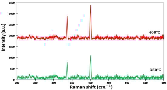
Figure 2.
Raman spectra for thin film obtained after sulfurization for time = 14 h and at two sulfurization temperatures.
From our Raman analyses, we calculated the intensity ratio of Elow and EHigh, which are related to sulfur distribution versus the crystallinity of the sample. Table 2 presents the difference in the contribution of sulfurization at different temperatures. It can be noticed that sulfurization increased with temperature, and the increase of the band gap highlights the influence of the sulfur position on the formation of intermediate levels in the band gap of the MS2 transition metal.
Table 2.
The intensity of the Elow mode and the intensity ratio of (Elow/EHigh) modes of the sample at different temperatures.
2.2.3. Transmission Electron Microscopy
Besides the variation nanoparticle size conforming to the results from transmission electron microscopy (TEM), as in Figure 3, the nature of sulfurization using this method affects the morphology of the resulting pyrite. For logical statistics, around 100 particles of a representative sample section were studied. Particle diameters were calculated, assuming an ideal spherical particle shape based on the measured area. In case of pyrite at 400 °C Figure 3a–c, the smallest particles in the range of 7–15 nm. Overall, average particle sizes were between 10 nm and 23 nm, and highest size was 39 nm. However, for pyrite at 350 °C (Figure 3d,e), we obtained only particles between 10 nm and 23 nm.
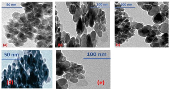
Figure 3.
(a–c): TEM image of at 400 °C. (d,e): TEM image of at 350 °C.
At higher magnification (Figure 3b,c), the surface of layers appeared granular with different grain sizes, and this enabled us to confirm the good crystallinity, showing its photovoltaic performance.
2.2.4. Optical Properties:
The mathematical equation for the optical band gap was given by Tauc et al. [67], and we used it in these studies as well [68,69]:
where .
- where is the absorbance coefficient, A is a constant, and is the photon energy. The variation vs. photon energy suggest an indirect band gap and for vs. photon energy , depicting a direct experimental transition. Notice that pyrite may have an indirect or direct transition [70,71]. The question is: will the band gap of our sample be indirect or direct? In fact, if iron pyrite layers have a direct band gap, it is very important for them to apply multispectral photovoltaic cells, because a direct band gap means a direct transition.
were plotted as functions of photon energy , with n = 4 and n = 1, and it is presented in Figure 4a–c. Only the plot of vs. has a straight line, indicating that pyrite film has a direct band gap energy for different temperatures of fabrication. Table 3 gives the acquired values of the band gap of pyrite film according to the two temperatures. pyrite had a low band gap when heat treated at 350 °C. Figure 4d shows the absorption coefficients, which were always high, and they were greater than .
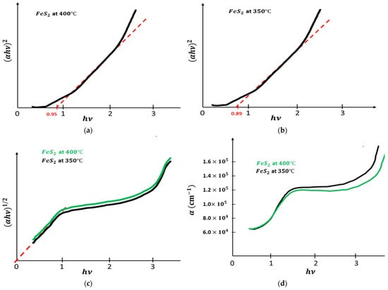
Figure 4.
(a): vs. . (b): vs. . (c): vs. . (d): vs. .
Table 3.
Exprimental band gap.
3. Band Structure
3.1. Computational Details
Density–Functional Theory [72,73] was used within the linear muffin-tin orbital method in the atomic-sphere approximation (LMTO-ASA). The LMTO ASA method was explained in detail in several reports [74,75,76]. In our calculations, we employed the self-consistent band calculations because they are the first principles of calculations utilizing density functional theory (see [72]), utilizing the local density approximation (see [77]), and utilizing numerical techniques based on the treatment of electron ion interaction in the pseudopotential approximation [78]. Moreover, the Hamiltonian Atomic Spheres Approximation is totally specified by the potential parameters. It generates moments from the eigenvectors of the Hamiltonian. Regarding specified potential, there is an individual correspondence between the energy of the wave function and the logarithmic derivative at the sphere radius. In essence, it is possible to specify either one. The potential P becomes simple because [79,80]:
where , , and are the “potential parameters” that parameterize P. defines the band “center of gravity”, is the “band width” parameter, which correlates with the bandwidth of l channel if it were uncoupled from the other channels, and is the “band distortion parameter”, which describes the deformations relative to a universal shape. Generally, small parameterization is a perfect method to study band structure.
First, we obtained the potential parameters for all atomic spheres. The muffin-tin potential constant was the crossing point of muffin-tin potential around and , and it is listed in Table 4. We had 24 symmetry operations. The initial sphere packing was equal to , and it was scaled to . The role of these empty spheres is to reduce the number of iterations in this system and to reduce the overlap between the spheres centered at and .
Table 4.
The muffin-tin potential constant.
3.2. Pyrite Crystal Structure
pyrite has a cubic crystal structure and the space group number 205 (with space- group ). In these structure, there are eight S atoms located in eight positions and four Fe atoms in four positions. The lattice parameters for pyrite are listed in Table 5.
Table 5.
Pyrite cell parameters.
In pyrite, each S atom is coordinated with three Fe atoms, for which the dimer pairs S_S are in tetrahedral sites, and each Fe atom is coordinated with six S atoms in octahedral sites.
Moreover, these structures contain pairs of sulfur S2 molecules, contrary to individual S atoms presented in the Figure 5a image of the overlapped unit cell of pyrite. To study the deviation from tetrahedral and octahedral geometries, we describe the correlation of the S-S bond length and cubic lattice. The relationships between our cell parameters are presented in Table 5. The structure of the pyrite is between 0.10 and 0.13 [81]. Our work demonstrated that the value of ranges between 0.111 and 0.113, showing significant effects of increased temperature conditioning pyrite. We noticed that the Fe sites had a small trigonal distortion, for which the S-Fe-S bond angles were at 350 °C and at 400 °C, and the three Fe-S-Fe bonds were between and for which the S sites were distorted from tetrahedral symmetry.
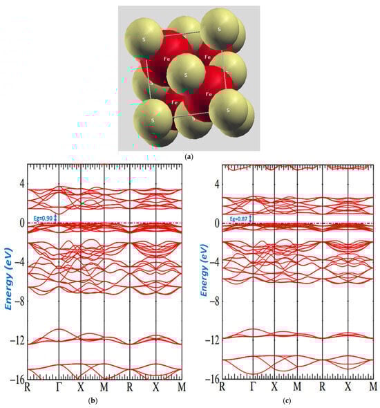
Figure 5.
(a): Image of overlap of pyrite. (b): Band structure of pyrite. (c): Band structure of pyrite at the temperature 350 °C and at the temperature 400 °C.
3.3. Energy Bands of Pyrite
The DFT energy bands for samples at different temperatures are shown in Figure 5b,c. The two figures provide the band structure on a form of energy that shows a general electronic structure. These figures present the region around the Fermi energy, which clearly depicts the details of a low conduction band and the highest valence band.
However, our band structure indicates that has a band gap semiconductor. We had four units in each unit cell and accommodated 40 occupied valence bands. The minimum conduction band was in , and the maximum valence band was at . The direct transition was observed at and had the values of o.87 eV and o.90 eV.
Our obtained results are different than those of Zhoa et al. [59] and Temmerman [58], who found 0.59 eV and 0.64 eV. Their gap was smaller than the experimental gap of 0.95 eV. Moreover, we were successful because our obtained gaps were significantly consistent with our optical gaps.
The calculated gap, optical gap, minimum band conduction CBmax, maximum valence band VBmax, and Fermi energy are summarized in Table 6. The bands are relative to bonding and antibonding pairs of S2 orbitals. In the range between −14 and 8 eV corresponding S3s, the structure of sulfur and these S3 states are predominant. The S 3p state is presented with a small addition of an Fe 3d function, starting at approximately −6 eV. Basically, these bands have Fe t2g hybridized with p orbitals, and they are below the Fermi energy. The lowest conduction band contained a combination of Fe eg orbitals. They were above Fermi energy. S3p Fe 3d is a preeminent character on the conduction band.
Table 6.
Band structure of Parameters.
Figure 6a,b presents the density of the states calculated, and it shows the states above and below the Fermi level of iron pyrite. It discloses the importance of hybridization between Fe and S states and the effect of temperature on the fabrication of pyrite.
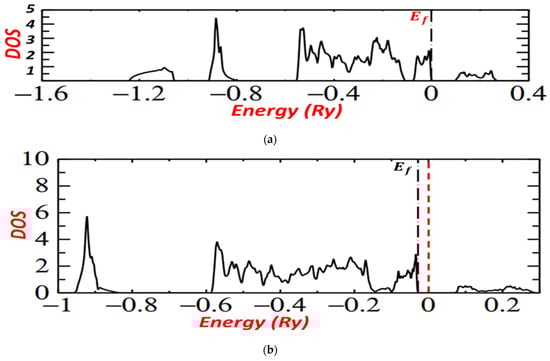
Figure 6.
(a): DOS for pyrite at the temperature 400 °C. (b): DOS for pyrite at the temperature 350 °C.
For the two graphs, level t2g lies between −0.1 Ry and 0, below the Fermi level, but for FeS2 pyrite prepared at 400 °C, it is near 0 and near Fermi level, which implies the good crystallite and electronic properties of iron pyrite prepared at 400 °C.
For both graphs, we noted that the conduction band was made entirely of Fe eg with Sp, marking that the conduction band was pure Sp while the valence bands were completely derived from the Fe t2g.
4. Pyrite in Photovoltaics: Modeling the ITO/ZnO/FeS2/ MoO3/Au/Ag Device
The synthesized pyrite samples were evaluated for the application of photodetector devices. We modeled ITO/ZnO///Au/Ag to study the improvement in solar cell characteristics realized by the increase of temperature in two cases of preparation of pyrite. We chose this application because it holds numerous benefits due its ability to be prepared at mild conditions, its low cost of chemicals, its mechanical flexibility, its better tuning, and due to it being a suitable alternative to silicone-based solar cells [82,83].
The device structure is presented in Figure 7a. ITO film was cut mechanically to obtain a 2.5 cm × 2.5 cm substrate. All substrates were cleaned in isopropanol, water, and soap for 15 min. For layer parameters, a washed indium tin oxide (ITO) glass substrate was managed by ultraviolet-ozone for 15 min. The ZnO layers were spin coated with 60 mg ml−1 ZnO/CHC3 solution annealed at 250 °C for 15 min in the air to form a ZnO layer of 100 nm. The MoO3 (20 nm) Au (30 nm) Ag (90 nm) layers were placed successively by thermal evaporation.
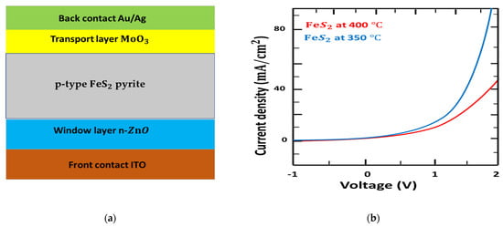
Figure 7.
(a): Device structure of ITO/ZnO/FeS2/ MoO3/Au/Ag. (b): Current density versus voltage (J–V) characteristics of fabricated solid solar cells.
In recent years, ZnO has become the prime candidate for organic photovoltaic cells [84] since its efficient improvement in stability. Here, we used the n-p layer heterojunction p-type pyrite solar cell using an n-type window layer. Additionally, MoO3 thin film can react as an effective electron-blocking layer or hole transporting to reduce the recombination of holes and electrons [85].
The schematic illustration characterization by exercising voltage from −1 to 2 V under a dark current using the modeled ITO/ZnO///Au/Ag structure, as presented in Figure 7b. The reported I-V characteristics and calculations for p-type pyrite at 350 °C were similar [86], principally below the onset voltage and the I-V curves above 1.5 V. However, the I-V curves for p-type pyrite at 400 °C showed a large difference above 1.4 V, for which the onset voltage was around 1.3 eV. This result corresponds well with the fabrication of pyrite, indicating that the nanostructures composed of pyrite at 400 °C are excellent in building n-p junction ZnO/ pyrite.
We concluded that, to obtain high-performing photovoltaic cells on ITO/ZnO///Au/Ag, it is necessary to focus on the quality of nanoparticles and nanostructures of pyrite, which improved by increasing the temperature of preparation (400 °C). We also mentioned to the effect of sulfur position, distance sulfur–sulfur, and temperature to band gap of pyrite.
5. Conclusions
This work was an inclusive study of pyrite. Our study reported on the increase of temperature of preparation, characterization, and calculation of band gap of pyrite. Our experiment demonstrated the effect of temperature of preparation on the favorable optical and electrical properties of pyrite. Our results confirmed that p-type pyrite is a good choice for fabricating solar cells. We also found the gap energy and sulfur-sulfur distance for samples with different temperatures of preparation, which were prepared by spray pyrolysis. We proved the correlation between growth parameters and the calculated band structure. The optical gap energy obtained in this work is in good agreement with the gap energy calculated by the LMTO-ASA method.
Our findings proved a significant powerful dependency between gap energy and distance sulfur–sulfur. Moreover, we concluded that the excellent crystallinity, nanoparticles, and nanostructures of pyrite confirm a more efficient photovoltaic application.
Finally, it is important to note that the high-performing photovoltaic cells on ITO/ZnO///Au/Ag positively improved the quality of nanoparticles and nanostructures of pyrite.
Author Contributions
Conceptualization, R.S. and R.A.A.; methodology, R.S. and R.A.A.; software, R.S. and R.A.A.; validation, R.S. and R.A.A.; formal analysis, R.S. and R.A.A.; investigation, R.S. and R.A.A.; resources, R.S.; data curation, R.S. and R.A.A.; writing—original draft preparation, R.S. and R.A.A.; writing—review and editing, R.S. and R.A.A.; visualization, R.S. and R.A.A.; supervision, R.S.; project administration, R.S. and R.A.A. All authors have read and agreed to the published version of the manuscript.
Funding
This research received no external funding.
Institutional Review Board Statement
Not applicable.
Informed Consent Statement
Not applicable.
Data Availability Statement
Not applicable.
Acknowledgments
The Author R. Abumousa would like to acknowledge the support of Prince Sultan University for paying the Article Processing Charges (APC) of this publication.
Conflicts of Interest
The authors declare no conflict of interest.
References
- Rao, C.N.R.; Deepak, F.L.; Gundiah, G.; Govindaraj, A. Effect of Mn Doping on Solvothermal Synthesis of CdS Nanowires. Prog. Solid State Chem. 2003, 31, 5. [Google Scholar] [CrossRef]
- Tang, K.B.; Qian, Y.T.; Zeng, J.H.; Yang, X.G. Solvothermal Route to Semiconductor Nanowires. Adv. Mater. 2003, 15, 448. [Google Scholar] [CrossRef]
- Kumar, S.; Nann, T. Shape control of II–VI semiconductor nanomaterials. Small 2006, 2, 316. [Google Scholar] [CrossRef]
- Altermatt, P.P.; Kiesewetter, T.; Ellmer, K.; Tributsch, H. Specifying targets of future research in photovoltaic devices containing pyrite (FeS2) by numerical modelling. Sol. Energy Mater. Sol. Cells 2002, 71, 181–195. [Google Scholar] [CrossRef]
- Ennaoui, A.; Fiechter, S.; Goslowsky, H.; Tributsch, H. Photoactive synthetic polycrystalline pyrite (FeS2). J. Electrochem. Soc. 1985, 132, 1579–1582. [Google Scholar] [CrossRef]
- Ennaoui, A.; Fiechter, S.; Pettenkofer, C.; Alonso-Vante, N.; Buker, K.; Bronold, M.; Hopfner, C.; Tributsch, H. Iron disulfide for solar-energy conversion. Sol. Energy Mater. Sol. Cells 1993, 29, 289–370. [Google Scholar] [CrossRef]
- Ennaoui, A.; Tributsch, H. Iron sulphide solar cells. Sol. Cells 1984, 13, 197–200. [Google Scholar] [CrossRef]
- Ennaoui, A.; Tributsch, H. Energetic characterization of the photoactive FeS2 (pyrite) interface. Sol. Energy Mater. 1986, 14, 461–474. [Google Scholar] [CrossRef]
- Smestad, G.; Ennaoui, A.; Fiechter, S.; Tributsch, H.; Hofmann, W.; Birkholz, M. Photoactive thin film semiconducting iron pyrite prepared by sulfurization of iron oxides. Sol. Energy Mater. 1990, 20, 149–165. [Google Scholar] [CrossRef]
- Sai, R.; Ezzaouia, H.; Nofal, M.M. Electronic structure of iron pyrite by the LMTO_ASA method. Results Phys. 2021, 22, 103950. [Google Scholar] [CrossRef]
- Huckaba, A.J.; Sanghyun, P.; Grancini, G.; Bastola, E.; Taek, C.K.; Younghui, L.; Bhandari, K.P.; Ballif, C.; Ellingson, R.J.; Nazeeruddin, M.K. Exceedingly Cheap Perovskite Solar Cells Using Iron Pyrite Hole Transport Materials. ChemistrySelect 2016, 1, 5316–5319. [Google Scholar] [CrossRef]
- Bragg, W.L. The analysis of crystals by the X-ray spectrometer. Proc. R. Soc. London. Ser. A. Contain. Pap. A Math. Phys. Character 1914, 89, 468–489. [Google Scholar]
- Abass, A.; Ahmed, Z.; Tahir, R. Absorption edge measurements in chemically deposited pyrite FeS2 thin layers. J. Appl. Phys. 1987, 61, 2339–2341. [Google Scholar] [CrossRef]
- Bhandari, K.P.; Roland, P.J.; Kinner, T.; Cao, Y.; Choi, H.; Jeong, S.; Ellingson, R.J. Analysis and characterization of iron pyrite nanocrystals and nanocrystalline thin films derived from bromide anion synthesis. J. Mater. Chem. A 2015, 3, 6853–6861. [Google Scholar] [CrossRef]
- Birkholz, M.; Fiechter, S.; Hartmann, A.; Tributsch, H. Sulfur deficiency in iron pyrite (FeS2−x) and its consequences for band-structure models. Phys. Rev. B 1991, 43, 11926. [Google Scholar] [CrossRef]
- Cabén-Acevedo, M.; Faber, M.S.; Tan, Y.; Hamers, R.J.; Jin, S. Synthesis and Properties of Semiconducting Iron Pyrite (FeS2) Nanowires. Nano Lett. 2012, 12, 1977–1982. [Google Scholar] [CrossRef] [PubMed]
- Cervantes, P.; Slanic, Z.; Bridges, F.; Knittle, E.; Williams, Q. The band gap and electrical resistivity of FeS2-pyrite at high pressures. J. Phys. Chem. Solids 2002, 63, 1927–1933. [Google Scholar] [CrossRef]
- Chen, X.; Wang, Z.; Wang, X.; Wan, J.; Liu, J.; Qian, Y. Single-source approach to cubic FeS2 crystallites and their optical and electrochemical properties. Inorg. Chem. 2005, 44, 951–954. [Google Scholar] [CrossRef]
- Christian Nweze, S.E. Optical Properties of Semiconducting Pyrite Deposited by Aerosol Assisted Chemical Vapour Deposition (AACVD) Method. Adv. Phys. Theor. Appl. 2014, 34, 21–29. [Google Scholar]
- Dong, Y.; Zheng, Y.; Duan, H.; Sun, Y.; Chen, Y. Formation of pyrite (FeS2) thin nano-films by thermal-sulfurating electrodeposition films at different temperature. Mater. Lett. 2005, 59, 2398–2402. [Google Scholar] [CrossRef]
- Ferrer, I.; Nevskaia, D.; De las Heras, C.; Sanchez, C. About the band gap nature of FeS 2 as determined from optical and photoelectrochemical measurements. Solid State Commun. 1990, 74, 913–916. [Google Scholar] [CrossRef]
- Ferrer, I.; Sanchez, C. Characterization of FeS2 thin films prepared by thermal sulfidation of flash evaporated iron. J. Appl. Phys. 1991, 70, 2641–2647. [Google Scholar] [CrossRef]
- Ho, C.; Huang, Y.; Tiong, K. Characterization of near band-edge properties of synthetic p-FeS2 iron pyrite from electrical and photoconductivity measurements. J. Alloys Compd. 2006, 422, 321–327. [Google Scholar] [CrossRef]
- Kim, H.T.; Nguyen, T.P.N.; Kim, C.-d.; Park, C. Formation mechanisms of pyrite (FeS2) nano-crystals synthesized by colloidal route in sulfur abundant environment. Mater. Chem. Phys. 2014, 148, 1095–1098. [Google Scholar] [CrossRef]
- Kou, W.W.; Seehra, M.S. Optical absorption in iron pyrite (FeS2). Phys. Rev. B 1978, 18, 7062. [Google Scholar] [CrossRef]
- Liu, Y.; Meng, L.; Zhang, L. Optical and electrical properties of FeS2 thin films with different thickness prepared by sulfurizing evaporated iron. Thin Solid Film. 2005, 479, 83–88. [Google Scholar] [CrossRef]
- Lucas, J.M.; Tuan, C.-C.; Lounis, S.D.; Britt, D.K.; Qiao, R.; Yang, W.; Lanzara, A.; Alivisatos, A.P. Ligand-Controlled Colloidal Synthesis and Electronic Structure Characterization of Cubic Iron Pyrite (FeS2) Nanocrystals. Chem. Mater. 2013, 25, 1615–1620. [Google Scholar] [CrossRef]
- Middya, S.; Layek, A.; Dey, A.; Ray, P.P. Synthesis of Nanocrystalline FeS2 with Increased Band Gap for Solar Energy Harvesting. J. Mater. Sci. Technol. 2014, 30, 770–775. [Google Scholar] [CrossRef]
- Ouertani, B.; Ouerfelli, J.; Saadoun, M.; Bessais, B.; Ezzaouia, H.; Bernede, J.C. Characterization of FeS2-pyrite thin films synthesized by sulphuration of amorphous iron oxide films pre-deposited by spray pyrolysis. J. Mater. Charact. 2005, 54, 431–437. [Google Scholar] [CrossRef]
- Prince, K.; Matteucci, M.; Kuepper, K.; Chiuzbaian, S.; Bartkowski, S.; Neumann, M. Core-level spectroscopic study of FeO and FeS2. Phys. Rev. B 2005, 71, 085102. [Google Scholar] [CrossRef]
- Puthussery, J.; Seefeld, S.; Berry, N.; Gibbs, M.; Law, M. Colloidal Iron Pyrite (FeS2) Nanocrystal Inks for Thin-Film Photovoltaics. J. Am. Chem. Soc. 2010, 133, 716–719. [Google Scholar] [CrossRef]
- Raturi, A.; Ndjeli, L.; Rabah, K. FeS2 thin films prepared by spray pyrolysis. Renew. Energy 1997, 11, 191–195. [Google Scholar] [CrossRef]
- Santos-Cruz, D.; Mayén-Hernández, S.A.; de Moure-Flores, F.; Arias-Cerón, J.S.; Santos-Cruz, J. Evaporated iron disulfide thin films with sulfurated annealing treatments. Mater. Sci. Semicond. Process. 2016, 42, 383–389. [Google Scholar] [CrossRef]
- Schlegel, A.; Wachter, P. Optical properties, phonons and electronic structure of iron pyrite (FeS2). J. Phys. C Solid State Phys. 1976, 9, 3363. [Google Scholar] [CrossRef]
- Seefeld, S.; Limpinsel, M.; Liu, Y.; Farhi, N.; Weber, A.; Zhang, Y.; Berry, N.; Kwon, Y.J.; Perkins, C.L.; Hemminger, J.C. Iron Pyrite Thin Films Synthesized from an Fe(acac)3 Ink. J. Am. Chem. Soc. 2013, 135, 4412–4424. [Google Scholar] [CrossRef]
- Subedi, I.; Bhandari, K.P.; Ellingson, R.J.; Podraza, N.J. Near infrared to ultraviolet optical properties of bulk single crystal and nanocrystal thin film iron pyrite. Nanotechnology 2016, 27, 295702. [Google Scholar] [CrossRef]
- Sun, K.; Su, Z.; Yang, J.; Han, Z.; Liu, F.; Lai, Y.; Li, J.; Liu, Y. Fabrication of pyrite FeS2 thin films by sulfurizing oxide precursor films deposited via successive ionic layer adsorption and reaction method. Thin Solid Film. 2013, 542, 123–128. [Google Scholar] [CrossRef]
- Wu, R.; Zheng, Y.; Zhang, X.; Sun, Y.; Xu, J.; Jian, J. Hydrothermal synthesis and crystal structure of pyrite. J. Cryst. Growth 2004, 266, 523–527. [Google Scholar] [CrossRef]
- Yu, Q.; Cai, S.; Jin, Z.; Yan, Z. Evolutions of composition, microstructure and optical properties of Mn-doped pyrite (FeS2) films prepared by chemical bath deposition. Mater. Res. Bull. 2013, 48, 3601–3606. [Google Scholar] [CrossRef]
- Karguppikar, A.; Vedeshwar, A. Electrical and optical properties of natural iron pyrite (FeS2). Phys. Status Solidi A 1988, 109, 549–558. [Google Scholar] [CrossRef]
- Antonov, V.; Germash, L.; Shpak, A.; Yaresko, A. Electronic structure, optical and X-ray emission spectra in FeS2. Phys. Status Solidi B 2009, 246, 411–416. [Google Scholar] [CrossRef]
- Bullett, D. Electronic structure of 3d pyrite- and marcasite-type sulphides. J. Phys. C Solid State Phys. 1982, 15, 6163. [Google Scholar] [CrossRef]
- Cai, J.; Philpott, M.R. Electronic structure of bulk and (0 0 1) surface layers of pyrite FeS2. Comput. Mater. Sci. 2004, 30, 358–363. [Google Scholar] [CrossRef]
- Choi, S.; Hu, J.; Abdallah, L.; Limpinsel, M.; Zhang, Y.; Zollner, S.; Wu, R.; Law, M. Pseudodielectric function and critical-point energies of iron pyrite. Phys. Rev. B 2012, 86, 115207. [Google Scholar] [CrossRef]
- Edelbro, R.; Sandstro, Å.; Paul, J. Full potential calculations on the electron bandstructures of Sphalerite, Pyrite and Chalcopyrite. Appl. Surf. Sci. 2003, 206, 300–313. [Google Scholar] [CrossRef]
- Folkerts, W.; Sawatzky, G.; Haas, C.; De Groot, R.; Hillebrecht, F. Electronic structure of some 3d transition-metal pyrites. J. Phys. C Solid State Phys. 1987, 20, 4135. [Google Scholar] [CrossRef]
- Herbert, F.; Krishnamoorthy, A.; Van Vliet, K.; Yildiz, B. Quantification of electronic band gap and surface states on FeS2(100). Surf. Sci. 2013, 618, 53–61. [Google Scholar] [CrossRef]
- Hu, J.; Zhang, Y.; Law, M.; Wu, R. Increasing the band gap of iron pyrite by alloying with oxygen. J. Am. Chem. Soc. 2012, 134, 13216–13219. [Google Scholar] [CrossRef]
- Hu, J.; Zhang, Y.; Law, M.; Wu, R. First-principles studies of the electronic properties of native and substitutional anionic defects in bulk iron pyrite. Phys. Rev. B 2012, 85, 085203. [Google Scholar] [CrossRef]
- Hung, A.; Muscat, J.; Yarovsky, I.; Russo, S.P. Density-functional theory studies of pyrite FeS2 (111) and (210) surfaces. Surf. Sci. 2002, 513, 511–524. [Google Scholar]
- Kolb, B.; Kolpak, A.M. Ultrafast band-gap oscillations in iron pyrite. Phys. Rev. B 2013, 88, 235208. [Google Scholar] [CrossRef]
- Muscat, J.; Hung, A.; Russo, S.; Yarovsky, I. First-principles studies of the structural and electronic properties of pyrite FeS2. Phys. Rev. B 2002, 65, 054107. [Google Scholar] [CrossRef]
- Opahle, I.; Koepernik, K.; Eschrig, H. Full potential band structure calculation of iron pyrite. Comput. Mater. Sci. 2000, 17, 206–210. [Google Scholar] [CrossRef]
- Opahle, I.; Koepernik, K.; Eschrig, H. Full-potential band-structure calculation of iron pyrite. Phys. Rev. Bs 1999, 60, 14035. [Google Scholar] [CrossRef]
- Qiu, G.; Xiao, Q.; Hu, Y.; Qin, W.; Wang, D. Theoretical study of the surface energy and electronic structure of pyrite FeS2 (100) using a total-energy pseudopotential method, CASTEP. J. Colloid Interface Sci. 2004, 270, 127–132. [Google Scholar] [CrossRef]
- Rosso, K.M.; Becker, U.; Hochella, M.F. Atomically resolved electronic structure of pyrite {100} surfaces: An experimental and theoretical investigation with implications for reactivity. Am. Mineral. 1999, 84, 1535–1548. [Google Scholar] [CrossRef]
- Sun, R.; Chan, M.; Ceder, G. First-principles electronic structure and relative stability of pyrite and marcasite: Implications for photovoltaic performance. Phys. Rev. B 2011, 83, 235311. [Google Scholar] [CrossRef]
- Temmerman, W.; Durham, P.; Vaughan, D. The electronic structures of the pyrite-type disulphides (MS2, where M = Mn, Fe, Co, Ni, Cu, Zn) and the bulk properties of pyrite from local density approximation (LDA) band structure calculations. Phys. Chem. Miner. 1993, 20, 248–254. [Google Scholar] [CrossRef]
- Zhao, G.; Callaway, J.; Hayashibara, M. Electronic structures of iron and cobalt pyrites. Phys. Rev. B 1993, 48, 15781. [Google Scholar] [CrossRef]
- Eyert, K.H.H.V.; Fiechter, S.; Tributsch, H. Electronic structure of FeS2: The crucial role of electron-lattice interaction. Phys. Rev. B 1998, 57, 6350–6359. [Google Scholar] [CrossRef]
- Voigt, B.; Moore, W.; Manno, M.; Walter, J.; Jeremiason, J.D.; Aydil, E.S.; Leighton, C. Transport evidence for sulfur vacancies as the origin of unintentional n-type doping in pyrite FeS2. ACS Appl. Mater. Interfaces 2019, 11, 15552–15563. [Google Scholar] [CrossRef]
- Rahman, M.; Boschloo, G.; Hagfeldt, A.; Edvinsson, T. On the mechanistic understanding of photovoltage loss in iron pyrite solar cells. Adv. Mater. 2020, 32, 1905653. [Google Scholar] [CrossRef] [PubMed]
- Jung, H.R.; Shin, S.W.; Gurav, K.; Gang, M.G.; Lee, J.Y.; Moon, J.H.; Kim, J.H. Evolution of detrimental secondary phases in unstable Cu2ZnSnS4 films during annealing. Electron. Mater. Lett. 2016, 12, 139–146. [Google Scholar] [CrossRef]
- Fan, D.; Zhang, R.; Zhu, Y.; Peng, H.; Zhang, J. Structural development and dynamic process in sulfurizing precursors to prepare Cu2ZnSnS4 absorber layer. J. Alloy. Comp. 2014, 583, 566–573. [Google Scholar] [CrossRef]
- Paal, M.; Nkrumah, I.; Ampong, F.K.; Ngbiche, D.U.; Nkum, R.K.; Boakye, F.K. The effect of deposition time and sulfurization temperature on the optical and structural properties of iron sulfide thin films deposited from acidic chemical baths. Sci. J. Univ. Zakho 2020, 8, 97–104. [Google Scholar] [CrossRef]
- Morrish, R.; Silverstein, R.; Wolden, C.A. Synthesis of Stoichiometric FeS2 through Plasma-Assisted Sulfurization of Fe2O3 Nanorods. J. Am. Chem. Soc. 2012, 134, 17854–17857. [Google Scholar] [CrossRef]
- Tauc, J.; Menth, A. States in the gap. J. Non-Cryst. Solids 1972, 8, 569–585. [Google Scholar] [CrossRef]
- Qin, H.; Jia, J.; Lin, L.; Ni, H.; Wang, M.; Meng, L. Pyrite FeS2 nanostructures: Synthesis, properties and applications. Mater. Sci. Eng. B 2018, 236, 104–124. [Google Scholar] [CrossRef]
- Xia, J.; Lu, X.; Gao, W.; Jiao, J.; Feng, H.; Chen, L. Hydrothermal growth of Sn4+-doped FeS2 cubes on FTO substrates and its photoelectrochemical properties. Electrochim. Acta 2011, 56, 6932–6939. [Google Scholar] [CrossRef]
- Ben Achour, Z.; Ktari, T.; Ouertani, B.; Touayar, O.; Bessais, B.; Brahim, J.B. Effect of doping level and spray time on zinc oxide thin films produced by spray pyrolysis for transparent electrodes applications. Sens. Actuators A 2007, 134, 447–451. [Google Scholar] [CrossRef]
- Ouertani, B.; Ouerfelli, J.; Saadoun, M.; Zribi, M.; Ben Rabha, M.; Bessaıs, B.; Ezzaouia, H. Optical and structural properties of FeSe2 thin films obtained by selenization of sprayed amorphous iron oxide films. Thin Solid Film. 2006, 511–512, 457–462. [Google Scholar] [CrossRef]
- Hohenberg, P.; Kohn, W. Inhomogeneous Electron Gas. Phys. Rev. 1964, 136, B864. [Google Scholar] [CrossRef]
- Kohn, W.; Sham, L.J. Self-Consistent Equations Including Exchange and Correlation Effects. Phys. Rev. 1965, 140, A1133. [Google Scholar] [CrossRef]
- Anderson, O.K. Linear methods in band theory. Phys. Rev. B 1975, 12, 123060. [Google Scholar] [CrossRef]
- Jan, J.P.; Skriver, H.L.J. Relativistic bandstructure and Fermi surface of PdTe2 by the LMTO method. Phys. F Met. Phys. 1977, 7, 1719. [Google Scholar] [CrossRef]
- Skriver, H.L. The LMTO Method; Springer: Berlin/Heidelberg, Germany, 1984; Volume 6, p. 2066. [Google Scholar]
- Hedin, L.; Lundqvist, B.I. Explicit local exchange-correlation potentials. J. Phys. C 1971, 4, 2064. [Google Scholar] [CrossRef]
- Louie, S.G.; Ho, K.-M.; Cohen, M.L. Self-consistent mixed-basis approach to the electronic structure of solids. Phys. Rev. B 1979, 19, 1774. [Google Scholar] [CrossRef]
- Andersen, O.K.; Jepsen, O.; Krier, G. Lectures on Methods of Electronic Structure Calculations; Kumar, V., Andersen, O.K., Mookerjee, A., Eds.; World Scientific Publishing Co.: Singapore, 1994; pp. 63–124. [Google Scholar]
- Andersen, O.K.; Arcangeli, C.; Tank, R.W.; Saha-Dasgupta, T.; Krier, G.; Jepsen, O.; Dasgupta, I. Tight-Binding Approach to Computational Materials Science; Colombo, L., Gonis, A., Turchi, P., Eds.; Materials Research Society: Pittsburgh, PA, USA, 1998; Volume 491, pp. 3–34. [Google Scholar]
- Hulliger, F.; Mooser, E. Semiconductivity in pyrite, marcasite and arsenopyrite phases. J. Phys. Chem. Solids. 1965, 26, 429. [Google Scholar] [CrossRef]
- Dyer-Smith, C.; Nelson, J.; Li, Y. Organic Solar Cells. In McEvoy’s Handbook of Photovoltaics; ELSEVIER: Amsterdam, The Netherlands, 2018; pp. 567–597. [Google Scholar]
- Che, X.; Li, Y.; Qu, Y.; Forrest, S.R. High fabrication yield organic tandem photovoltaics combining vacuum-and solution- processed subcells with 15% efficiency. Nat. Energy 2018, 3, 422–427. [Google Scholar] [CrossRef]
- Si, H.; Liao, Q.; Zhang, Z.; Li, Y.; Yang, X.; Zhang, G.; Kang, Z.; Zhang, Y. An Innovative design of perovskite solar cells with Al2O3 Inserting at ZnO/perovskite interface for improving the performance and stability. Nano Energy 2016, 22, 223–231. [Google Scholar] [CrossRef]
- Wang, D.Y.; Jiang, Y.T.; Lin, C.C.; Li, S.S.; Wang, Y.T.; Chen, C.C.; Chen, C.W. Solution-Processable Pyrite FeS2 Nanocrystals for the Fabrication of Heterojunction Photodiodes with Visible to NIR Photodetection. Adv. Mater. 2012, 24, 3415. [Google Scholar] [CrossRef] [PubMed]
- Moon, D.G.; Cho, A.; Park, J.H.; Ahn, S.; Kwon, H.; Cho, Y.S.; Ahn, S. Iron pyrite thin films deposited via non-vacuum direct coating of iron-salt/ethanol-based precursor solutions. J. Mater. Chem. A 2014, 2, 17779. [Google Scholar] [CrossRef]


Disclaimer/Publisher’s Note: The statements, opinions and data contained in all publications are solely those of the individual author(s) and contributor(s) and not of MDPI and/or the editor(s). MDPI and/or the editor(s) disclaim responsibility for any injury to people or property resulting from any ideas, methods, instructions or products referred to in the content. |
© 2023 by the authors. Licensee MDPI, Basel, Switzerland. This article is an open access article distributed under the terms and conditions of the Creative Commons Attribution (CC BY) license (https://creativecommons.org/licenses/by/4.0/).