Article

Impact of Hot Isostatic Pressing Temperature on Tensile Properties of TA15 Titanium Alloy Produced via Laser Powder Bed Fusion

1
Anhui Laboratory of Aeronautical Equipment Measurement, Control and Reverse Engineering, State-Owned Wuhu Machinery Factory, Wuhu 241007, China
2
Institute of Advanced Wear & Corrosion Resistant and Functional Materials, Jinan University, Guangzhou 510632, China
*
Author to whom correspondence should be addressed.
Coatings 2023, 13(10), 1742; https://doi.org/10.3390/coatings13101742
Submission received: 30 August 2023 / Revised: 4 October 2023 / Accepted: 5 October 2023 / Published: 7 October 2023
(This article belongs to the Special Issue Surface Treatment on Metals and Their Alloys)

Abstract

:
TA15 titanium alloy holds great significance as a crucial material in the aerospace industry. In order to gain deeper insights into the influence of hot isostatic pressing (HIP) temperature on the tensile characteristics of materials formed through laser powder bed fusion (L-PBF), a comparative heat treatment experiment was crafted, aligning with the HIP treatment temperature settings. Specifically, the temperatures selected for this investigation were 900 °C, 940 °C, 980 °C, and 1020 °C, while the duration of the holding time was set at 2 h. Notably, the microstructure within the β phase region demonstrated distinct disparities between the HIP-treated specimens and those subjected to heat treatment. The heat-treated specimens exhibited the formation of Widmanstatten structure at 980 °C, while the metallographic structure of the HIP-treated specimens consisted of the lath α phase. In heat-treated specimens, an upward trend in temperature from 900 °C to 1020 °C led to a gradual decrease in UTS (995 MPa, 947 MPa, 886 MPa, and 892 MPa), YS (921 MPa, 865 MPa, 799 MPa, and 784 MPa). The elongation (15.7%,14.6%, and 13.3%) diminished as the temperature increased from 900 °C to 980 °C. At 1020 °C, the elongation slightly increased to 13.9%. The HIP-treated specimens showcased a declining trend in UTS (1008.5 MPa, 947 MPa, 886 MPa, and 892 MPa) and YS (939 MPa, 897.5 MPa, 839.5 MPa, and 844.5 MPa) with an increase in HIP treatment temperature from 900 °C to 980 °C, after which they experienced a slight increment upon further elevation to 1020 °C. The elongation (16%,18.3%, and 20.5%) demonstrated a remarkable improvement from 900 °C to 980 °C. At 1020 °C, the elongation decreased to 17.5%.

1. Introduction

TA15 alloy is a high aluminum-equivalent near-α titanium alloy. Its exceptional blend of strength, fracture toughness, welding performance, fatigue limit, and corrosion resistance at both ambient and elevated temperatures has propelled its extensive utilization in the aeronautical and astronautical industries [1,2,3,4]. Notably, titanium alloys fabricated through the L-PBF exhibit unparalleled mechanical properties in comparison to their cast and wrought counterparts [1,2,3,4]. It is primarily attributed to developing exquisite columnar grains and intricate phase structures during rapid solidification under high temperature gradients [4,5,6,7,8,9,10,11,12]. A comprehensive examination of L-PBF-fabricated and forged titanium alloys reveals a notable disparity in ductility, with diminished plasticity observed in the former. This can be attributed to inherent imperfections prevalent in L-PBF components, encompassing incomplete fusion, porosity, and residual stresses within the solidified material.
At present, many studies have been carried out on the thermal processing and microstructural characterization of TA15 alloys [13,14,15,16,17,18]. It has been revealed that the malleability of the TA15 titanium alloy at ambient temperatures experiences a substantial augmentation subsequent to thermal treatment or hot isostatic pressing. However, it remains inferior to 18% [15,16,19,20]. The elongation of the specimen produced by L-PBF was found to be less than 12% [12,15]. Subsequent to the L-PBF procedure, the implementation of post-treatment, particularly heat treatment, and HIP, assumes a crucial role in customizing the microstructure and optimizing mechanical properties, with a specific focus on augmenting tensile ductility. In the case of as-printed specimens, it was unfortunately impossible to eliminate defects through the use of a heat treatment alone, which led to little increase in plasticity [21]. In a HIP treatment, parts were pressurized using an inert gas at high temperatures while subsurface defects were removed using hydrostatic pressure. It was possible to acquire 100% densification of the L-PBF-formed components after HIP treatment, which improved their overall mechanical properties [14]. By employing the HIP technique, one can tailor the microstructural characteristics of the as-printed specimens while simultaneously mitigating their imperfections [17,22]. As a result, the mechanical attributes of the as-printed titanium alloys experienced a remarkable augmentation subsequent to the HIP treatment.
Although considerable research on the HIP treatment of as-printed Ti-based alloys has been reported [13,14,15,16,17,18], a thorough understanding of how HIP treatment temperature influences microstructure and mechanical properties, especially the temperature near or above the β transition temperature, remains elusive. The reportorial HIP treatment temperature of titanium alloys formed by L-PBF was found to vary within the range of 895 °C to 955 °C [14] because it presented the various types of microstructure after post-fabrication heat treatments below or above the β transition temperature and the solution treatment above the transition temperature of the β phase caused the excessive grain growth as a result of the disappearance of the primary α phase during microstructural evolution [23]. The plasticity progressively increases with rising temperatures [4,24,25]. Aerospace components necessitate materials with exceptional plasticity at typical temperatures. Consequently, unraveling the influence of hot isostatic pressing temperature on the malleability of titanium alloys under ordinary circumstances becomes imperative in attaining paramount plasticity levels. Further, it is imperative to gain a mechanistic understanding of the microstructure-tuning mechanism through HIP treatment in order to further optimize the performance of as-printed parts.
This study employed the L-PBF technique to manufacture the TA15 specimens, followed by hot isostatic pressing at varying temperatures near the β transus point. The maximum elongation of the hot isostatic pressing treatment was explored, reaching an impressive 20.5% at 980 °C. An investigation was undertaken to examine the impact of the temperature during the HIP treatment on the microstructure and tensile properties of the material. To gain a deeper comprehension of how the HIP treatment temperature influences the tensile behavior of L-PBF-produced materials, a comparative heat treatment experiment was devised, where the specimens were subjected to the same temperature as the HIP treatment. Moreover, the heat-treated specimens were meticulously characterized and tested to elucidate how the HIP treatment affects the microstructure and tensile properties.

2. Materials and Methods

The spherical powder of TA15 alloy was prepared by vacuum gas atomization. Figure 1 shows the SEM image of TA15 powder. The mean particle size of TA15 powder was 40 μm in diameter. The chemical composition of the TA15 alloy powder is presented in Table 1. L-PBF-fabricated specimens with a dimension of 14 × 65 × 14 mm (X, Y, and Z), as shown in Figure 2a, were fabricated on the TC4 substrate. The L-PBF process was carried out using a Renishaw AM 500E L-PBF system (UK) with a laser spot size of 80 μm. The hatch spacing was 120 μm, the powder layer thickness was 30 μm, the laser power was 200 W, and the scan speed was 1.3 m/s. The building chamber was filled with an inert argon atmosphere, and the O2 content was below 1000 ppm.
L-PBF-formed specimens were subsequently subjected to HIP treatment using RD400 equipment (China) under 130 MPa for 2 h to investigate the effect of HIP treatment temperature on the tensile behavior of TA15 titanium alloy. The working medium for the RD400 is argon. The temperature was set at 900 °C, 940 °C, 980 °C, and 1020 °C, respectively. The mean furnace cooling rate was about 2~4 °C/min. Additional L-PBF-formed specimens were treated in a vacuum heat treatment furnace (2 × 10⁻² Pa), VAF-80 equipment, at 900 °C, 940 °C, 980 °C, and 1020 °C, respectively, for 2 h. The mean furnace cooling rate was to about 2~4 °C/min. Then, the L-PBF-formed specimens, HIP-treated specimens, and heat-treated specimens for microstructure characterization were prepared using metallographic polishing procedures and etched with Kroll reagent (HF:HNO3:H2O = 1:3:7). The metallographic structure was characterized by the Zeiss Axio Observer 3 m optical microscope (OM, Carl Zeiss AG, Jena, Germany). The grain orientation and phase distribution of the L-PBF-formed specimens, HIP-treated specimens, and heat-treated specimens were characterized by using an Oxford EBSD camera (Oxford Instruments, Abingdon, UK). The surface of the specimens was prepared by electrolytically. The scanning step was 0.1 μm. The EBSD data were analyzed using HKL Channel 5 software. The differential scanning calorimetry (DSC) test was carried out on the Netzsch STA 449 F3 testing machine (NETZSCH, Selb, Bavaria, Germany) to test the β transus point with a heating rate of 20 °C/min. The L-PBF-formed, HIP-treated, and heat-treated TA15 tensile test specimens perpendicular to the manufacturing direction were machined with a gauge length of 25 mm and a diameter of 5 mm (shown in Figure 2a) and then carried on the UTM5504 universal testing machine (China) at room temperature with strain rates of 0.00025 s−1. The number of test specimens for each condition of tensile testing was 3. The tensile fracture morphology was characterized using secondary electron mode on the Zeiss Supra55(VP) scanning electron microscopy (SEM).

3. Results and Discussion

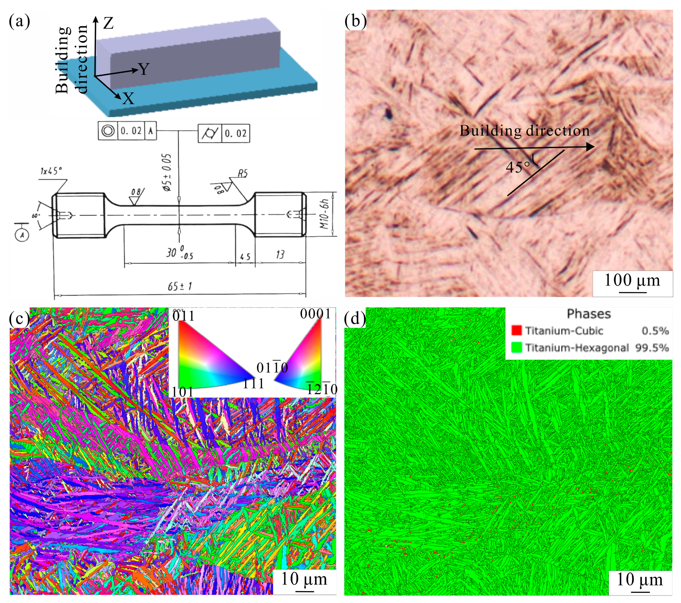
3.1. Microstructure of L-PBF-Fabricated Specimens

Figure 2 shows a technical drawing of the specimen, the optical microscopy image, EBSD grain orientation and inverse pole figure (IPF), and grain boundary and phase map obtained from EBSD results of L-PBF-formed TA15 specimens of the longitudinal section. The L-PBF-formed TA15 specimen was characterized by long and wide columnar grains in the building direction, as well as fine needle-shaped α′ martensite throughout the build. Since the heat flow direction of the L-PBF manufacturing process was in opposition to the forming direction of the grains [12,26], the growth of prior β grains was characterized through directional solidification, and, as a result of the high thermal gradient induced by the laser beam combined with a high cooling rate (103 K/s) [12], this caused almost all β domains to undergo the α′ martensitic transformation without diffusion. According to Figure 2b, the orientation of the α′ grains is arranged at ~45° to the direction of construction [6]. It was related to the Burger orientation relation of cubic prior β transformed into a hexagon [6]. Most orientation relationships were based on the phase’s growth direction at 45°. As reported in other research [6,27], different size scales of α′ martensite can be found around the previously formed grains due to the subsequent in-process cyclic heat treatment, as shown in Figure 2c. The phase maps of L-PBF specimens obtained from EBSD results were shown in Figure 2d. The volume fraction of α′ martensite was 99.5%, and the volume fraction of β phase was 0.5%. The volume fraction of the β phase was the lowest compared to the heat-treated specimen and HIP-treated specimen described in Section 3.2. This was because the formation of non-diffusion α′ martensitic consumes a lot of β phases, forming elements V and Mo [28].

3.2. Microstructure Evolution

The L-PBF-fabricated TA15 alloy exhibited a remarkable combination of high tensile strength and limited elongation upon fracture (typically ranging from 5% to 10%) [29]. This characteristic was widely recognized as a significant impediment to its practical applications. In order to meet the desired mechanical properties for specific applications, it was imperative to employ appropriate post-processing techniques, such as heat treatment and HIP treatment. Given the presence of defects, including residual stresses and pores, in the L-PBF-formed specimens, it became necessary to subject them to HIP treatment. To gain deeper insights into the influence of HIP treatment temperature on the plasticity pattern of L-PBF-formed materials, a comparative heat treatment experiment was devised, employing the same temperature as that used in the HIP treatment.
To elucidate the impact of heat treatment and HIP treatment temperatures on the microstructure of the TA15 alloy, various temperatures close to the β transus temperature were employed in treating the L-PBF-formed specimens. The β transus temperature was determined via differential scanning calorimetry (DSC) testing, with the DSC curve during the heating process of the L-PBF-formed TA15 alloy represented in Figure 3. A conspicuous exothermic peak was clearly observable between 960 °C and 1000 °C, signifying that the β transus temperature fell within this range. By analyzing the DDSC peak curve (a derivative of the DSC curve), the β transus temperature was accurately determined to be 977 °C.

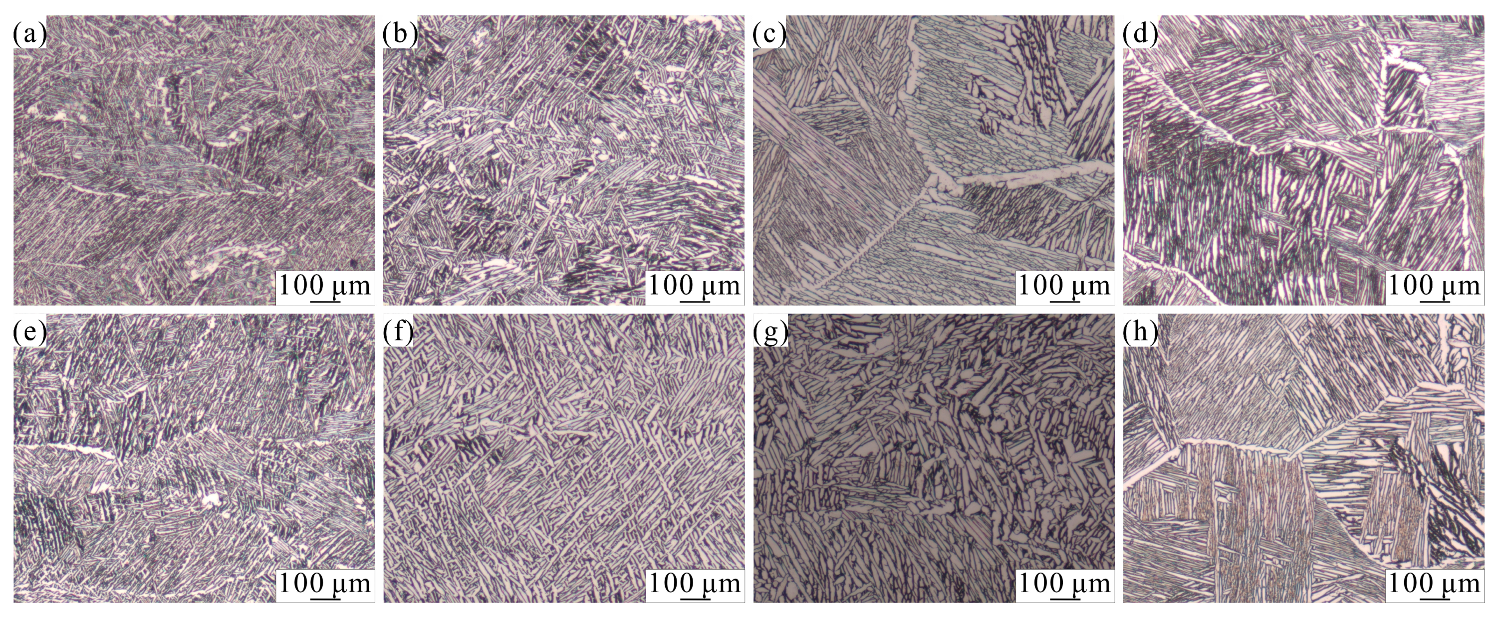
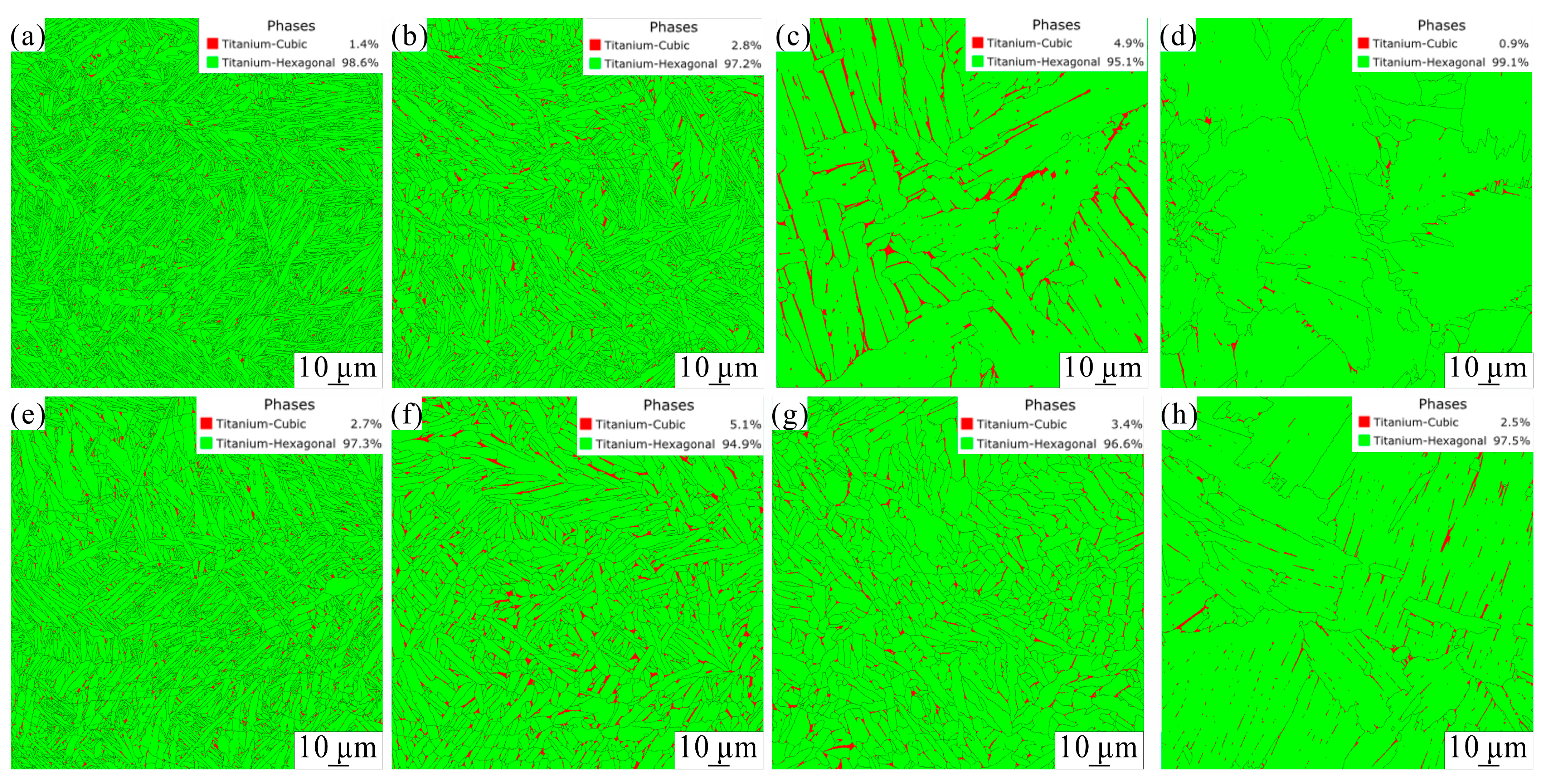
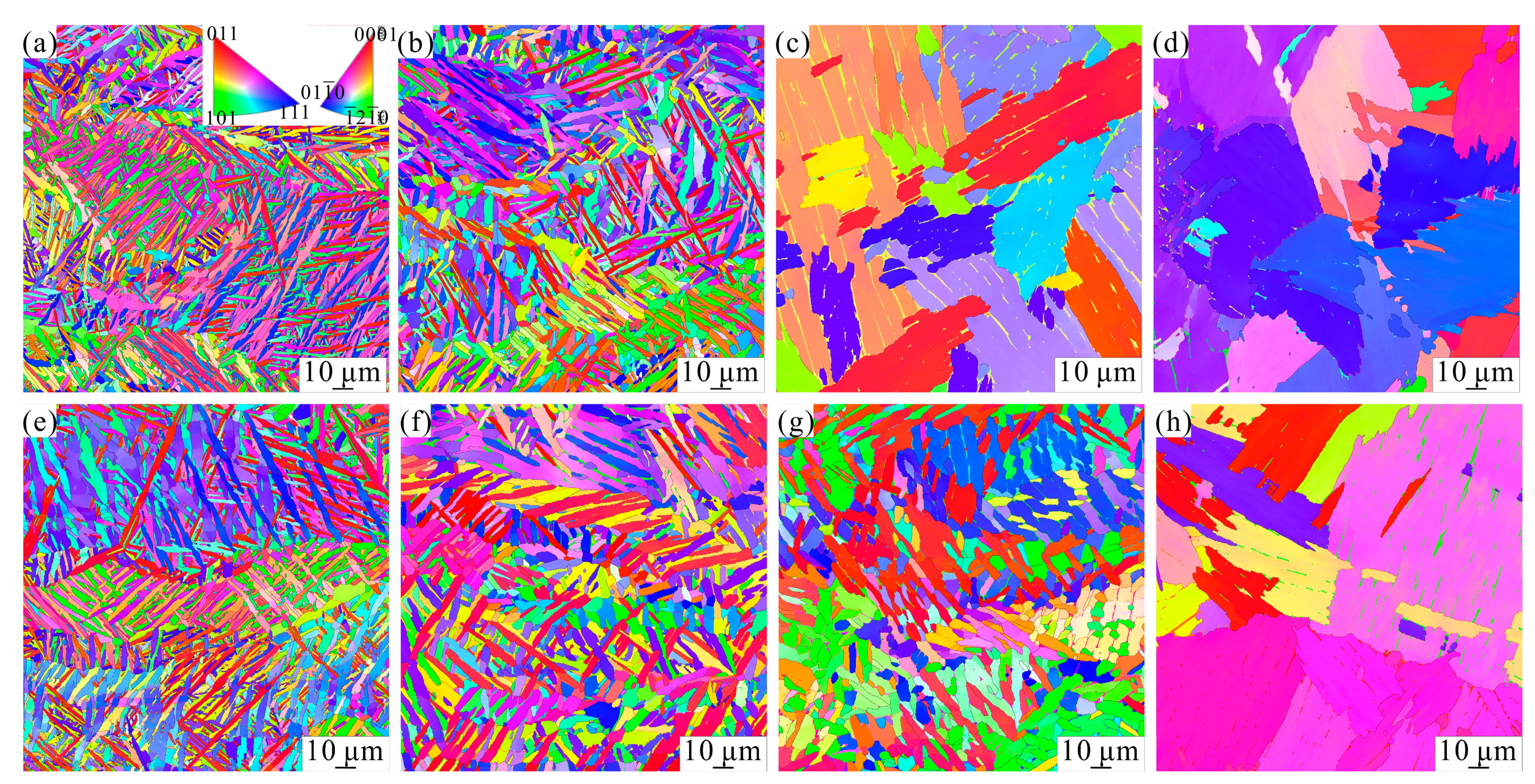
3.2.1. Heat Treatment

Figure 4a–d depicts the metallographic structure of L-PBF-fabricated TA15 specimens of longitudinal section after heat treatment at different temperatures, which were 900 °C, 940 °C, 980 °C, and 1020 °C, respectively. It was found that the microstructure of the specimen at 900 °C and 940 °C was similar to that of the specimen formed by L-PBF. As the temperature increased, the pre-existing elongated β grains alongside the building direction became coarser. The widths of the prior β grains at 900 °C and 940 °C were 81 μm and 106 μm, respectively, which were more prominent than that of the as-printed specimen (72 μm). It has been demonstrated that the latter α′ martensite has retained the growth characteristics of the α martensite, as shown in Figure 4a,b, which indicates that the heat-treated microstructures at 900 °C and 940 °C possessed solid tissue heredity [7,23,30]. During the heating process, the transformation of α′ → α + β occurred when the temperature was higher than the α′ martensitic transformation temperature (575 °C) [7]. When the temperature was above 800 °C, the α′ phase was completely decomposed into the α-Ti or β-Ti phase [23,30]. Thus, the β matrix comprised fine lath-like α martensite. As the chemical elements, V and Mo, diffused to the α′ martensite edge, the lath-like α phase formed, and the α phase retained the orientation relationship. In order to decrease the interfacial energy, the α grain size increased. The equivalent circle diameters of α grain at 900 °C and 940 °C were 2.5 μm and 3.2 μm, respectively, larger than that of the L-PBF-formed specimen (2.0 μm).
Upon reaching temperatures of 980 °C and 1020 °C, the material underwent heat treatment that surpassed the β transus temperature. This resulted in the formation of β-equiaxed grains, which were accompanied by continuous grain boundary α phase and lamellar α phase, leading to a significant increase in α grain size. Consequently, the heat-treated microstructure lost its L-PBF-fabricated specimen characteristics. The average size of the equiaxial β grain was measured as 276 μm and 293 μm at 980 °C and 1020 °C, respectively. At these temperatures, the lamellar α martensite microstructure maintained a random grain orientation. The formation process of the α phase during heat treatment above the β transus temperature differed from that below the β transition temperature. At 980 °C and 1020 °C, the majority of the α phase transformed into the β phase, resulting in the nucleation and growth of β-equiaxed grains. During the subsequent cooling process, the α phase nucleated at the boundaries of the β grains and grew within the grain interior when the cooling rate was slow. This led to the presence of continuous grain boundaries α phase and lamellar α phase. The orientation of the α grain remained random. Additionally, a small amount of β phase was retained due to the segregation of β-phase-stabilizing elements [18]. Figure 5a–d depict the grain boundary and phase maps of the heat-treated specimens obtained from EBSD results at various temperatures. The volume fractions of the β phase in the heat-treated specimens at 900 °C, 940 °C, 980 °C, and 1020 °C were measured as 1.4%, 2.8%, 4.9%, and 0.9% respectively. As the temperature increased from 900 °C to 980 °C, the volume fraction of the β phase also increased. This was due to the fact that the volume fraction of the β phase generally increases with temperature in the two-phase region [12]. However, when the temperature surpassed the β transus temperature, the volume fraction of the β phase decreased. This was because the segregation of the β-phase stabilizing elements decreased as the temperature rose. Consequently, the volume fraction of the β phase at 1020 °C was the lowest.
Figure 6a–d show the EBSD grain orientation and inverse pole figure (IPF) maps of the TA15 specimens of longitudinal sections heat-treated at different temperatures. As the heat treatment temperature increased, the α phase experienced coarsening, progressing from 900 °C to 1020 °C. Notably, the coarsening became particularly pronounced once the temperature surpassed the β transus temperature. This phenomenon can be attributed to the significantly high atomic diffusion coefficients observed in the β phases (10−13 m2/s at 1000 °C [13,18]). The heat-treated specimens at 980 °C and 1020 °C displayed identical crystallographic orientations in their lamellar α martensite structures. This similarity resulted from the re-nucleation of the α phase at β grain boundaries, causing it to grow within the interior of the β grains. Such characteristics are inherent to the TA15 alloy [18]. At 900 °C and 940 °C, the β phase primarily distributed along triangular grain boundaries, exhibiting a granular morphology (Figure 5a,b). However, as the temperature of heat treatment rose to 980 °C and 1020 °C, notable changes in the morphology and distribution of the β phase occurred. Specifically, at 980 °C, the β phase took on a lath-like shape, whereas at 1020 °C, it assumed a short rod-like configuration (Figure 5c,d). Additionally, the distribution of the lath-like β phase aligned with the lamellar α phase interface at 980 °C, while at 1020 °C, it followed the boundaries of the equiaxed β grains. This alteration can be attributed to changes in the volume fraction of the β phase.

3.2.2. HIP Treatment

The impact of HIP treatment and heat treatment on the evolution of microstructure exhibited similarities. However, notable discrepancies emerged in proximity to the critical β transus temperature. Embodied within Figure 4e–h lie captivating visual depictions of the metallographic composition of L-PBF-fabricated TA15 specimens subsequent to HIP treatment at 900 °C, 940 °C, 980 °C, and 1020 °C. The elongated grains alongside the building direction throughout the build were retained after the HIP treatment at 900 °C, 940 °C, and 980 °C, which indicated that the HIP-treated microstructures above the β transus temperature still possessed solid tissue heredity. The widths of the prior β grains at 900 °C, 940 °C, and 980 °C were 89 μm, 105 μm, and 112 μm, respectively, which were larger than that of the heat treatment specimen. The prior β grains comprised fine lath-like α martensite, similar to the heat-treated specimen. The equivalent circle diameters of α grain at 900 °C, 940 °C, and 980 °C were 2.7 μm, 3.7 μm, and 4.4 μm, respectively, larger than that of the heat-treated specimen (2.5 μm at 900 °C, 3.2 μm at 940 °C). The grain size of the HIP-treated specimen was larger than that of the heat-treated specimen, which was characteristic of HIP treatment [31]. The microstructural characteristics of the specimen subjected to HIP treatment at a temperature of 980 °C exhibited notable distinctions from those of the heat-treated specimen. Specifically, the heat-treated specimen, when exposed to a temperature of 980 °C, displayed equiaxed grains of the β phase, featuring the presence of lamellar α phases and continuous α phases along the grain boundaries—a phenomenon commonly referred to as the Widmanstatten structure. On the other hand, in stark contrast, the microstructure of the HIP-treated specimen at 980 °C showcased elongated grains, characterized by the presence of coarse lath-like α phases and equiaxed α phases within the prior β grains. The exposure temperature above β transus temperature was the key to forming the Widmanstatten structure. The lamellar α phase could be obtained by completely heating above the β transus temperature. Once the temperature was reduced to below the β transus temperature, the α phase nucleated on the β grain boundary. Then the α phase grew into the β grain in lamellar form, forming the Widmanstatten structure. The temperature of HIP treatment and heat treatment was the same and higher than the β transus temperature. The heat-treated and HIP-treated specimens were generally both Widmanstatten structures, but this was not the case with the HIP-treated specimen in this paper. It could be seen that both the coarse lath-like α phase and prior β grain boundary equiaxed α phase were the same type of microstructure as at 900 °C and 940 °C, which indicated that the HIP treatment at 980 °C was still in the two-phase region. The lamellar α phase increased the slips distance of dislocation, reducing the strength and deformation ability, While the equiaxed α phase had strong crack initiation resistance, which was beneficial to the improvement of plasticity, indicating that HIP-treated specimens at 980 °C had better mechanical properties. When the HIP treatment temperature reached 1020 °C, the β equiaxed grains formed. The mean size of the equiaxial β grain at 1020 °C was 296 μm, and the Widmanstatten structure was observed, which was similar to the heat-treated specimen. This indicated that HIP treatment was as detrimental to plasticity as heat treatment when the temperature exceeded the β phase transus temperature.
Figure 5e–h it present the EBSD grain boundary and phase maps of the HIP-treated specimens at distinct temperatures. The volume fractions of the β phase in the HIP-treated specimen were recorded as 2.7%, 5.1%, 3.4%, and 2.5% at 900 °C, 940 °C, 980 °C, and 1020 °C respectively. Interestingly, the volume fraction of the β phase in the HIP-treated specimen exceeded that of the heat treatment specimen, signifying an increase in the percentage of the β phase due to the influence of HIP treatment. Notably, the β phase predominantly occupied the α triangular grain boundary at 900 °C, 940 °C, and 980 °C, manifesting a granular morphology at 900 °C and assuming a short rod-like configuration at 940 °C and 980 °C. With the elevation of HIP treatment temperature to 1020 °C, alterations in the morphology and distribution of the β phase occurred, resulting in a granular shape, which correlated with a reduction in volume fraction. The distribution of the granular β phase primarily aligned with the prior β grain and colonies boundary. Figure 6e–h show the EBSD grain orientation and inverse pole figure (IPF) maps of the HIP-treated TA15 specimens at different temperatures. Analogous to the heat-treated specimen, the α phase exhibited coarsening in the temperature range of 900 °C to 980 °C, with a significant increase in coarsening when the temperature reached 1020 °C. At 1020 °C, the lamellar α martensite structures of the HIP-treated specimens showcased identical crystallographic orientation.

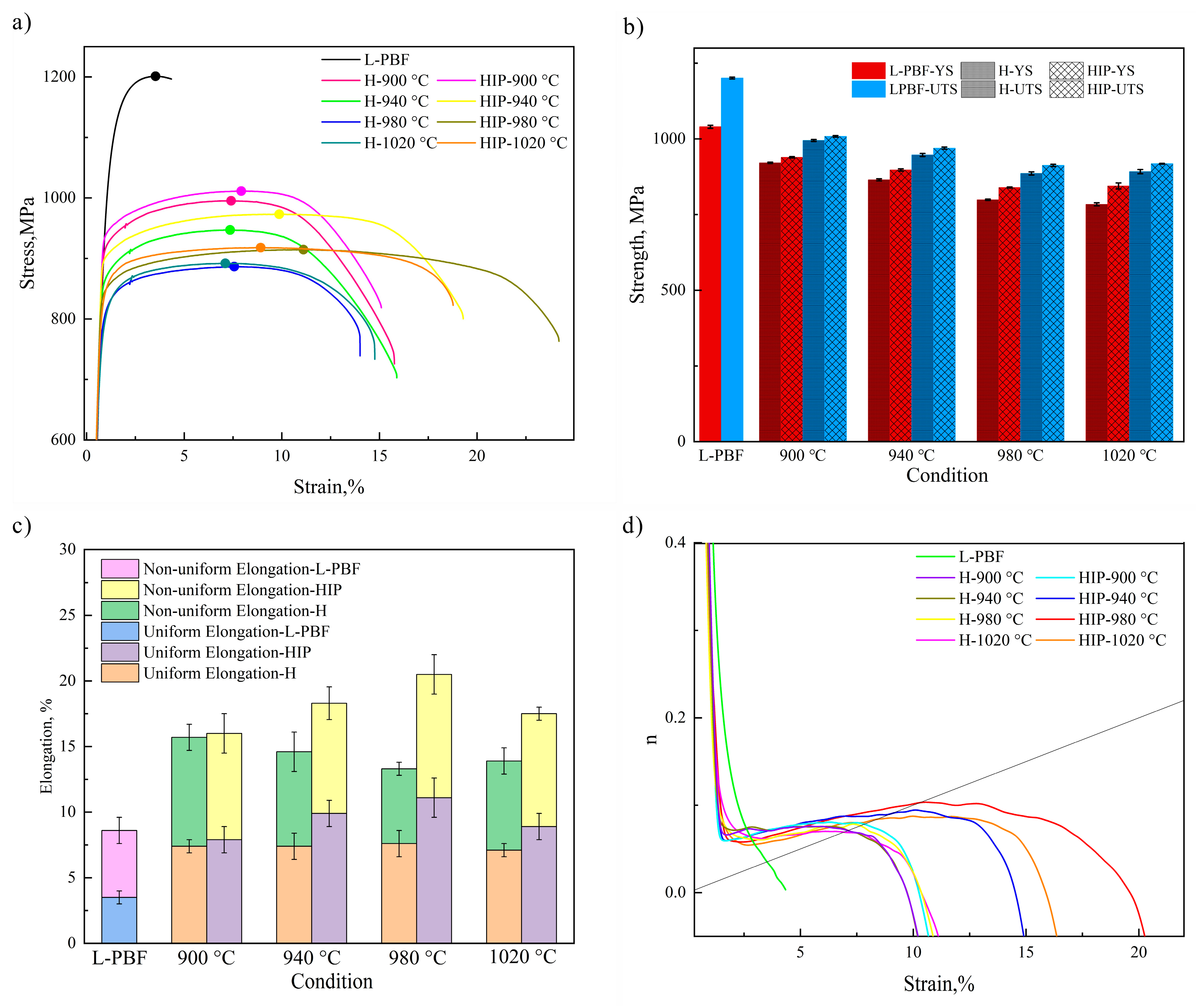
3.3. Tensile Properties

Figure 7a shows the engineering stress–strain curves of L-PBF specimens and specimens after HIP treatment and heat treatment at different temperatures in the vertical manufacturing direction. The ultimate tensile strength (UTS) and yield strength (YS) of TA15 tensile specimens are presented in Figure 7b. The UTS and YS of the L-PBF-formed specimen were 1201 MPa and 1040 MPa, respectively. After heat treatment and hot isostatic pressing, The UTS and YS decreased significantly. In the temperature range of 900~980 °C, with the increase of HIP treatment and heat treatment temperature, the UTS and YS were significantly reduced, and the UTS of the HIP-treated specimens was reduced from 1008.5 MPa to 912.5 MPa; the YS of the HIP-treated specimen was reduced from 941 MPa to 839.5 MPa. The UTS of the heat-treated specimen was reduced from 995 MPa to 892 MPa, and the YS of the heat-treated specimen was decreased from 921 MPa to 784 MPa. The strength of the HIP-treated specimen was higher than that of the heat-treated specimen at the same treated temperature, which was related to their microstructure characteristics. The evolution of different microstructure characteristics (porosity, grain size, etc.) had different effects on strength. The decrease in porosity hardened the material, while grain growth softened it. After heat treatment and HIP treatment, the grain size increased obviously, which led to the decrease in strength. However, the HIP treatment eliminated defects such as pores, which led to an increase in strength [18]. Thus, the strength of the HIP specimen was higher than that of heat-treated specimens. When the treatment temperature was increased to 1020 °C, the UTS and YS of the HIP-treated specimen were slightly improved, while the UTS and YS of the heat-treated specimen decreased. The relationship between UTS and grain diameter satisfied the Hall–Petch relationship [25]. The UTS decreased with increasing grain size. As the temperature increased, the grain size grew, and the strength decreased. However, for the HIP-treated specimens, when the treatment temperature increased to 1020 °C, the microstructure of HIP-treated specimens changed from coarse lath-like α grain to lamellar α grain. Thus, the strength improved.
Figure 7c shows the elongation after fracture. The elongation of the L-PBF-formed specimen was the lowest, 8.6%. The elongation of the HIP-treated specimen was higher than that of the heat-treated specimen. The EBSD analysis showed clearly that the β phase fraction of the HIP-treated specimen was more than that of the heat-treated specimen. Since β grains were usually softer than α grains and the β phase has more slip systems than the α phase, it could be concluded that the presence of this β phase facilitated the deformation of the HIP-treated specimens. In addition, the elimination of pore defects improved plasticity. It was noteworthy that the elongation of the HIP-treated specimen significantly increased from 16% to 20.5% in the temperature range of 900~980 °C and then decreased to 17.5% at 1020 °C, while the elongation of the heat-treated specimen significantly decreased from 15.7% to 13.3% in the temperature range of 900~980 °C and then increased to 13.9% at 1020 °C. As known to all, the microstructure itself determines the mechanical properties. The α grain size of heat-treated specimens was increased with increasing temperature. Thus, for the heat-treated specimens, the elongation of the heat-treated specimen decreased with increasing temperature in the temperature range of 900~980 °C. For the HIP-treated specimens, although the complete elimination of pores increased the plasticity with the increase of temperature when the temperature reached 1020 °C, Widmanstatten structure was formed, which was unfavorable to plasticity.
Uniform elongation was considered a suitable parameter for evaluating the tensile plasticity of L-PBF-formed materials [5]. It could be seen from Figure 7c that the uniform elongation of the HIP-treated specimen increased with the increasing temperature from 900 °C to 980 °C and decreased at 1020 °C. When the HIP treatment temperature reached 980 °C, although the maximum engineering stress was the lowest, it showed excellent plasticity, with the engineering strain of uniform plastic deformation reaching 0.1. The alteration of uniform elongation of the heat-treated specimen was comparatively small in the temperature range of 900~1020 °C. The work-hardening behavior described by n i n c r = d   l n σ / d   l n ε   of L-PBF-formed specimens and specimens after HIP treatment and heat treatment at different temperatures is plotted in Figure 7d, where σ is the true stress and ε is the true strain. At the beginning of straining, TA15 tensile specimens treated by HIP and heat treatment at different temperatures exhibited similar work-hardening behaviors since their microstructures were composed of α and β phases with similar volume fractions [32]. For the heat-treated specimens in the temperature range of 900~980 °C and HIP-treated specimens in the temperature range of 900~940 °C, their nincr value decreases rapidly with increasing strain. As a consequence, the strain level achieved satisfies Connor’s necking initiation criterion, leading to a diminished uniform elongation. The specimens treated by HIP at 980 °C showed a more significant hardening rate at higher strain levels, so the uniform elongation levels were high. For HIP-treated and heat-treated specimens at 1020 °C, although their nincr initially decreased more slowly, the hardening rate was lower at higher strain levels, resulting in lower uniform elongation levels.

3.4. Fracture Analysis

In order to understand the tensile fracture mechanism of HIP-treated and heat-treated TA15 specimens at different temperatures, the fracture characteristics of the tensile specimens were characterized. Figure 8 shows the tensile fracture morphology of L-PBF specimens, as well as specimens following HIP treatment and heat treatment at different temperatures. In both L-PBF-formed and heat-treated specimens, pores were observed, suggesting that heat treatment contributed nothing to the elimination of porosity defects. However, such pore defects were not found in the HIP-treated specimens. Thus, the effect of HIP treatment on eliminating pore defects was prominent. The fracture surfaces of TA15 titanium alloy treated by heat-treated at 900 °C and 940 °C and HIP at 900 °C, 940 °C, 980 °C were almost cup-cone fracture surfaces exhibiting typical shear slip and flat part, as shown in Figure 8b,c, f–h, which manifest the typical features of trans-granular fracture. The dimples were observed on the fracture, and its size and depth increased with the increasing HIP treatment temperature, which meant that plasticity increased with increasing temperature. Figure 8d–e,i shows the fracture surface of TA15 titanium alloy heat treated at 980 °C and 1020 °C and HIP treated at 1020 °C. A mixture of river-like cleavage planes and ductile dimples on the cleavage steps was distributed on the fracture surface, which meant that the fracture mode was a trans-granular and inter-granular mixed failure. This was unfavorable to plasticity. In the fracture process, the trans-granular fracture was dominant, and the fracture surface appeared to have a pronounced tearing ridge, consistent with its lower elongation.

4. Conclusions

The investigation delved into the intricate evolution of the microstructure and tensile properties in TA15 titanium alloys. These alloys were initially fabricated through the employment of L-PBF, and subsequently underwent treatments involving HIP treatment and heat treatment. The experiments were meticulously executed at temperatures below, near, and above the β transition temperature. The potential application of our research findings lies in the manufacturing of titanium-alloy-reinforced components for aerospace applications. Therefore, the implications of our paper hold considerable significance within this industry. In summation, the key findings derived from our research can be succinctly summarized as follows:
(1)
Notable disparities were observed in the microstructure between the heat-treated and HIP-treated specimens within the β phase region. Specifically, the heat-treated specimens exhibited the formation of a distinct Widmanstatten structure at the elevated temperature of 980 °C. In contrast, the microstructure of the HIP-treated specimens was exclusively characterized by the presence of thicker lath α phases. This particular attribute played a pivotal role in augmenting the plasticity, resulting in a staggering increase of up to 20.5%.
(2)
In heat-treated specimens, an upward trend in temperature from 900 °C to 1020 °C led to a gradual decrease in UTS (995 MPa, 947 MPa, 886 MPa, and 892 MPa), YS (921 MPa, 865 MPa, 799 MPa, and 784 MPa). The elongation (15.7%, 14.6%, and 13.3%) diminished as the temperature increased from 900 °C to 980 °C. At 1020 °C, the elongation slightly increased to 13.9%. The HIP-treated specimens showcased a declining trend in UTS (1008.5 MPa, 947 MPa, 886 MPa, and 892 MPa) and YS (939 MPa, 897.5 MPa, 839.5 MPa, and 844.5 MPa) with an increase in HIP treatment temperature from 900 °C to 980 °C, after which they experienced a slight increment upon further elevation to 1020 °C. The elongation (16%, 18.3%, and 20.5%) demonstrated a remarkable improvement from 900 °C to 980 °C. At 1020 °C, the elongation decreased to 17.5%.

Author Contributions

Conceptualization, S.C. and J.H.; Formal analysis, J.H. and Z.C.; Project administration, S.C. and J.H.; Validation, S.X., X.C. and D.D.; Writing—original draft, S.C. and Z.C.; Writing—review & editing, S.C., Q.L. and Q.W. All authors have read and agreed to the published version of the manuscript.

Funding

This research was funded by Wuhu Science and Technology Major Project, Grant No. 2021zd08, Anhui key research and development project high-tech special—high-tech field, Grant No. 202304a05020067, Defense Industrial Technology Development Program, Grant No. JCKY2020130C024.

Institutional Review Board Statement

Not applicable.

Informed Consent Statement

Not applicable.

Data Availability Statement

The data presented in this study are available upon request from the authors.

Conflicts of Interest

The authors declare no conflict of interest.

References

  1. Zhang, Y.; Zhang, S.; Zou, Z.; Shi, Y. Achieving an ideal combination of strength and plasticity in additive manufactured Ti–6.5Al–2Zr–1Mo–1V alloy through the development of tri-modal microstructure. Mater. Sci. Eng. A 2022, 840, 142944. [Google Scholar] [CrossRef]
  2. Liu, J.; Li, Y.; Zhu, Y.; Yang, Y.; Zhang, R.; Zhang, Z.; Huang, A.; Zhang, K. Enhancing high-temperature strength and ductility in laser powder bed fusion Ti–6.5Al–2Zr–1Mo–1V alloy via heat treatment optimization. Mater. Sci. Eng. A 2022, 859, 144201. [Google Scholar] [CrossRef]
  3. Rovetta, R.; Ginestra, P.; Ferraro, R.M.; Zohar-Hauber, K.; Giliani, S.; Ceretti, E. Building Orientation and Post Processing of Ti6Al4V Produced by Laser Powder Bed Fusion Process. J. Manuf. Mater. Process. 2023, 7, 43. [Google Scholar] [CrossRef]
  4. Rahulan, N.; Sharma, S.S.; Rakesh, N.; Sambhu, R. A short review on mechanical properties of SLM titanium alloys based on recent research works. Mater. Today Proc. 2022, 54, 451–456. [Google Scholar] [CrossRef]
  5. Voisin, T.; Calta, N.P.; Khairallah, S.A.; Forien, J.B.; Balogh, L.; Cunningham, R.W.; Rollett, A.D.; Wang, Y.M. Defects-dictated tensile properties of selective laser melted Ti-6Al-4V. Mater. Des. 2018, 158, 113–126. [Google Scholar]
  6. Bedmar, J.; de la Pezuela, J.; Riquelme, A.; Torres, B.; Rams, J. Impact of Remelting in the Microstructure and Corrosion Properties of the Ti6Al4V Fabricated by Selective Laser Melting. Coatings 2022, 12, 284. [Google Scholar] [CrossRef]
  7. Yeganeh, M.; Shahryari, Z.; Talib Khanjar, A.; Hajizadeh, Z.; Shabani, F. Inclusions and Segregations in the Selective Laser-Melted Alloys: A Review. Coatings 2023, 13, 1295. [Google Scholar]
  8. Zheng, X.; Wang, K.; Zhang, C.; Xin, R.; Liu, Q. Evolution mechanism of lamellar α and interlayered β during hot compression of TC21 titanium alloy with a widmanstatten structure. Chin. J. Aeronaut. 2022, 35, 475–483. [Google Scholar] [CrossRef]
  9. Ponnusamy, P.; Sharma, B.; Masood, S.H.; Rashid, R.A.R.; Rashid, R.; Palanisamy, S.; Ruan, D. A study of tensile behavior of SLM processed 17-4 PH stainless steel. Mater. Today Proc. 2021, 45, 4531–4534. [Google Scholar] [CrossRef]
  10. Zhao, D.L.; Han, C.J.; Li, Y.; Li, J.J.; Zhou, K.; Wei, Q.S.; Liu, J.; Shi, Y.S. Improvement on mechanical properties and corrosion resistance of titanium-tantalum alloys in-situ fabricated via selective laser melting. J. Alloys Compd. 2019, 804, 288–298. [Google Scholar] [CrossRef]
  11. Aufa, A.N.; Hassan, M.Z.; Ismail, Z. Recent advances in Ti-6Al-4V additively manufactured by selective laser melting for biomedical implants: Prospect development. J. Alloys Compd. 2022, 896, 163072. [Google Scholar]
  12. Wu, X.P.; Zhang, D.Y.; Guo, Y.W.; Zhang, T.; Liu, Z.Y. Microstructure and mechanical evolution behavior of LPBF (laser powder bed fusion)-fabricated TA15 alloy. J. Alloys Compd. 2021, 873, 159639. [Google Scholar] [CrossRef]
  13. Cai, C.; Song, B.; Xue, P.; Wei, Q.; Yan, C.; Shi, Y. A novel near α-Ti alloy prepared by hot isostatic pressing: Microstructure evolution mechanism and high temperature tensile properties. Mater. Des. 2016, 106, 371–379. [Google Scholar] [CrossRef]
  14. Li, P.; Warner, D.H.; Pegues, J.W.; Roach, M.D.; Shamsaei, N.; Phan, N. Investigation of the mechanisms by which hot isostatic pressing improves the fatigue performance of powder bed fused Ti-6Al-4V. Int. J. Fatigue 2019, 120, 342–352. [Google Scholar] [PubMed]
  15. Liu, Z.; Li, R.; Chen, D.; Sun, Y.; He, B.; Zou, Y. Enhanced tensile ductility of an additively manufactured near-α titanium alloy by microscale shear banding. Int. J. Plast. 2022, 157, 103387. [Google Scholar]
  16. Xu, L.; Guo, R.P.; Bai, C.G.; Lei, J.F.; Yang, R. Effect of Hot Isostatic Pressing Conditions and Cooling Rate on Microstructure and Properties of Ti-6Al-4V Alloy from Atomized Powder. J. Mater. Sci. Technol. 2014, 30, 1289–1295. [Google Scholar] [CrossRef]
  17. Yu, H.C.; Li, F.Z.; Wang, Z.M.; Zeng, X.Y. Fatigue performances of selective laser melted Ti-6Al-4V alloy: Influence of surface finishing, hot isostatic pressing and heat treatments. Int. J. Fatigue 2019, 120, 175–183. [Google Scholar] [CrossRef]
  18. Cai, C.; Gao, X.; Teng, Q.; Kiran, R.; Liu, J.; Wei, Q.; Shi, Y. Hot isostatic pressing of a near α-Ti alloy: Temperature optimization, microstructural evolution and mechanical performance evaluation. Mater. Sci. Eng. A 2021, 802, 140426. [Google Scholar] [CrossRef]
  19. Li, R.; Wang, H.; He, B.; Li, Z.; Zhu, Y.; Zheng, D.; Tian, X.; Zhang, S. Effect of α texture on the anisotropy of yield strength in Ti–6Al–2Zr–1Mo–1V alloy fabricated by laser directed energy deposition technique. Mater. Sci. Eng. A 2021, 824, 141771. [Google Scholar]
  20. Wang, Y.; Xue, X.; Kou, H.; Chang, J.; Yin, Z.; Li, J. Improvement of microstructure homogenous and tensile properties of powder hot isostatic pressed TA15 titanium alloy via heat treatment. Mater. Lett. 2022, 311, 131585. [Google Scholar] [CrossRef]
  21. Huang, S.; Sun, B.B.; Guo, S.Q. Microstructure and property evaluation of TA15 titanium alloy fabricated by selective laser melting after heat treatment. Opt. Laser Technol. 2021, 144, 107422. [Google Scholar]
  22. Lv, Z.J.; Li, H.F.; Che, L.D.; Chen, S.; Zhang, P.J.; He, J.; Wu, Z.F.; Niu, S.T.; Li, X.Y. Effects of HIP Process Parameters on Microstructure and Mechanical Properties of Ti-6Al-4V Fabricated by SLM. Metals 2023, 13, 991. [Google Scholar] [CrossRef]
  23. Vilaro, T.; Colin, C.; Bartout, J.D. As-Fabricated and Heat-Treated Microstructures of the Ti-6Al-4V Alloy Processed by Selective Laser Melting. Metall. Mater. Trans. A 2011, 42, 3190–3199. [Google Scholar] [CrossRef]
  24. Jiang, J.J.; Ren, Z.H.; Ma, Z.B.; Zhang, T.; Zhang, P.; Zhang, D.Z.; Mao, Z.F. Mechanical properties and microstructural evolution of TA15 Ti alloy processed by selective laser melting before and after annealing. Mater. Sci. Eng. A 2020, 772, 138742. [Google Scholar] [CrossRef]
  25. Hu, Y.B.; Chen, H.N.; Jia, X.H.; Liang, X.D.; Lei, J.B. Heat treatment of titanium manufactured by selective laser melting: Microstructure and tensile properties. J. Mater. Res. Technol. 2022, 18, 245–254. [Google Scholar] [CrossRef]
  26. Simonelli, M.; Tse, Y.Y.; Tuck, C. Effect of the build orientation on the mechanical properties and fracture modes of SLM Ti–6Al–4V. Mater. Sci. Eng. A 2014, 616, 1–11. [Google Scholar] [CrossRef]
  27. Kazantseva, N.; Krakhmalev, P.; Thuvander, M.; Yadroitsev, I.; Vinogradova, N.; Ezhov, I. Martensitic transformations in Ti-6Al-4V (ELI) alloy manufactured by 3D Printing. Mater. Charact. 2018, 146, 101–112. [Google Scholar] [CrossRef]
  28. Herzog, D.; Seyda, V.; Wycisk, E.; Emmelmann, C. Additive manufacturing of metals. Acta Mater. 2016, 117, 371–392. [Google Scholar]
  29. Zhang, T.; Liu, C.-T. Design of titanium alloys by additive manufacturing: A critical review. Adv. Powder Mater. 2022, 1, 100014. [Google Scholar]
  30. Zhang, X.Y.; Fang, G.; Leeflang, S.; Bottger, A.J.; Zadpoor, A.A.; Zhou, J. Effect of subtransus heat treatment on the microstructure and mechanical properties of additively manufactured Ti-6Al-4V alloy. J. Alloys Compd. 2018, 735, 1562–1575. [Google Scholar] [CrossRef]
  31. Hattal, A.; Mukhtarova, K.; Djemai, M.; Chauveau, T.; Hocini, A.; Fouchet, J.J.; Bacroix, B.; Gubicza, J.; Dirras, G. Effect of hot isostatic pressing on microstructure and mechanical properties of Ti6Al4V-zirconia nanocomposites processed by laser-powder bed fusion. Mater. Des. 2022, 214, 110392. [Google Scholar] [CrossRef]
  32. de Formanoir, C.; Brulard, A.; Vivès, S.; Martin, G.; Prima, F.; Michotte, S.; Rivière, E.; Dolimont, A.; Godet, S. A strategy to improve the work-hardening behavior of Ti–6Al–4V parts produced by additive manufacturing. Mater. Res. Lett. 2016, 5, 201–208. [Google Scholar] [CrossRef]
Figure 1. SEM image of TA15 powder.
Coatings 13 01742 g001
Figure 2. L-PBF-formed TA15 specimens: (a) technical drawing of the specimen, (b) optical microscopy images, (c) EBSD grain orientation and inverse pole figure (IPF), and (d) grain boundary and phase map obtained from EBSD results of the longitudinal section.
Coatings 13 01742 g002
Figure 3. The DSC curve during the heating rate of L-PBF-formed TA15 alloy.
Coatings 13 01742 g003
Figure 4. Optical microscope images of TA15 specimen of longitudinal section at different conditions: (a) heat-treated at 900 °C, (b) heat-treated at 940 °C, (c) heat-treated at 980 °C, (d) heat-treated at 1020 °C, (e) HIP-treated at 900 °C, (f) HIP-treated at 940 °C, (g) HIP-treated at 980 °C, and (h) HIP-treated at 1020 °C.
Coatings 13 01742 g004
Figure 5. The grain boundary and phase maps of L-PBF specimens of longitudinal section obtained from EBSD results at different conditions: (a) heat-treated at 900 °C, (b) heat-treated at 940 °C, (c) heat-treated at 980 °C, (d) heat-treated at 1020 °C, (e) HIP-treated at 900 °C, (f) HIP-treated at 940 °C, (g) HIP-treated at 980 °C, and (h) HIP-treated at 1020 °C.
Coatings 13 01742 g005
Figure 6. EBSD grain orientation and inverse pole figure (IPF) maps of the TA15 specimens of longitudinal section at different conditions, (a) heat-treated at 900 °C, (b) heat-treated at 940 °C, (c) heat-treated at 980 °C, (d) heat-treated at 1020 °C, (e) HIP treated at 900 °C, (f) HIP treated at 940 °C, (g) HIP treated at 980 °C, (h) HIP treated at 1020 °C.
Coatings 13 01742 g006
Figure 7. (a) The engineering stress–strain curves of L-PBF specimens and specimens after HIP treatment and heat treatment at different temperatures in the vertical manufacturing direction; the dot in the figure indicates the location of the maximum stress. (b) The ultimate tensile strength (UTS), and yield strength (YS) of L-PBF specimens and specimens after HIP treatment, and heat treatment at different temperatures. (c) The elongation of after fracture of L-PBF specimens and specimens after HIP treatment and heat treatment at different temperatures. (d) The work-hardening behavior described by n i n c r = d   l n σ / d   l n ε   of L-PBF specimens and specimens after HIP treatment and heat treatment at different temperatures. L-PBF specimens are depicted in the legend as L-PBF, heat-treated specimens are depicted in the legend as H, and HIP-treated specimens are depicted in the legend as HIP.
Coatings 13 01742 g007
Figure 8. SEM images of the tensile fracture morphology of L-PBF-formed TA15 specimens. (a) as-built condition, (b) heat-treated at 900 °C, (c) heat-treated at 940 °C, (d) heat-treated at 980 °C, (e) heat-treated at 1020 °C, (f) HIP-treated at 900 °C, (g) HIP-treated at 940 °C, (h) HIP-treated at 980 °C, and (i) HIP-treated at 1020 °C, the red bordered image is a high magnification of the yellow boxed area.
Coatings 13 01742 g008
Table 1. Chemical composition of the TA15 alloy powder (wt.%).
TiAlZrMoVSiFeCOH
Bal6.322.041.291.750.010.020.0060.050.0015
Disclaimer/Publisher’s Note: The statements, opinions and data contained in all publications are solely those of the individual author(s) and contributor(s) and not of MDPI and/or the editor(s). MDPI and/or the editor(s) disclaim responsibility for any injury to people or property resulting from any ideas, methods, instructions or products referred to in the content.

