Abstract
Diamond-like carbon (DLC) coatings doped with Ti and Ni elements were deposited on 316 L stainless steel substrate using magnetron sputtering technology. The morphology, microstructures, and performances of the coatings were detected using scanning electron microscopy, a Raman spectrometer, nanoindenter, scratch tester, and a tribological machine. The effects of element doping on the microstructures, friction and wear properties of DLC coatings were analyzed. The results revealed that Ti/Ni doping ensures the uniform cover and tight fit of DLC coatings on the substrate. Additionally, Ni-doped DLC coatings have a much smoother surface and denser texture with higher bonding strength and enhanced hardness (7.5 GPa) though Ti doping also can improve the bond strength to some extent. The presence of Ni both in the 316 L substrate and in Ni-doped DLC coatings improves interface matching, decreases structural differences, and increases bonding strength. Moreover, the presence of Ni effectively inhibits oxidation and corrosion in friction interfaces, stabilizes the friction coefficient, and enhances wear resistance. Therefore, based on this study, it was concluded that reasonable matching between the dopant elements and the substrates can effectively improve the performance of DLC coatings.
1. Introduction
Stainless steel is currently widely applied in industrial equipment [1]. However, friction failure is an unavoidable problem and the friction and wear performances of 316 L stainless steel need to improve to increase engineering part service life. The deposition of coatings with high wear resistance on the surfaces of workpieces can effectively suppress wear failure and extend service life. Diamond-like carbon (DLC) coating is an amorphous carbon film composed of graphite-like sp2-C and diamond-like sp3-C [2]. DLC achieves high hardness, wear resistance, and thermal conductivity, along with excellent corrosion resistance [3,4]. In addition, when utilized as a protective coating, DLC can effectively improve the friction and wear performances of stainless steel parts [5].
Although DLC coatings have excellent performance, the large hardness gradients, thermal expansion coefficients, and structural mismatches between coatings and substrates result in high internal stress, poor adhesion, and easy detachment issues, which restrict the applications of DLC coatings [4,6]. Recent research has shown that the additions of transition layers and element doping can effectively reduce internal stress, improve bonding strength, and enhance wear resistance [7,8]. In addition, elements such as copper (Cu), chromium (Cr), titanium (Ti), nickel (Ni), boron (B), and nitrogen (N) have been widely introduced into DLC coatings as transition layers or dopant elements [9,10,11,12,13]. However, no regular theory of element doping influences on DLC coatings has been determined due to mutual interactions and the complex DLC forming process. The bonding strength between the DLC coating and substrate, especially steel substrate, is poor, mainly due to diffusion of carbon into the iron lattice, leading to the appearance of a graphite layer at the interfaces during the DLC preparation process, which weakens the bonding force [14]. Moreover, the thermal expansion coefficient of the coating and the phases in steel is diverse, resulting in higher internal stress. Thus, Ti is usually used as the transition element [9] due to its high affinity for carbon and good compatibility with steel. Recent studies have shown that the presence of Ti in DLC coatings decreases the sp3 hybrid carbon bonding fraction and improves corrosion resistance. Moreover, TiC nanocrystals may be formed in the coating, improving self-lubricating properties, hardness, and adhesion; lowering internal stress; and heightening the tribological properties of DLC coatings [15,16]. In addition, Ni, a carbon-dissolving element, is also used to form a transition layer in DLC preparation. In theory, if there is a small amount of Ni or other elements both in the substrate and coatings, the difference between them will decrease. Consequently, the structural mismatch and hardness gradient between coating and substrate may be reduced. Vilius et al. [17] compared the performances of Cr- and Ni-doped DLC coatings and found that Ni DLC coatings have the highest adhesion force and the highest nanohardness. It was found that Ni doping increases the sp2/sp3 ratio of coatings, the nanocrystalline graphite clusters formed in metal-doped DLC coatings are larger, and there are fewer defects on the coating surface [18].
In this study, DLC coatings doped with Ti and Ni were prepared using magnetron sputtering. Then, the bonding strength and structure of the resulting DLC coatings were investigated and their properties analyzed.
2. Experimental Details
The DLC coating was prepared using magnetron sputtering (physical vapor deposition method). Graphite, Ni, and Ti with purity values of 99.99 wt.% were used as targets, and Ar with a purity of 99.99 wt.% was used as the working gas. During the deposition process, the ionization vacuum was maintained at approximately 0.5 Pa and the temperature was 100 °C. DLC coatings doped with Ti (named TDLC) and Ni (named NDLC) elements were deposited on 316 L stainless steel, respectively. The pure DLC coatings with no metal element doping were labeled DLC. The size of the 316 sheet used was 30 mm × 30 mm × 3 mm.
The coating surface and microstructure were characterized using a field emission scanning electron microscope (SEM, MERLINCompact, Germany) and a Raman spectrometer (Thermo Fischer DXR, America). The laser wavelength was 532 nm, and the spectral measurement range was between 800 and 2000 cm−1. The indentation/scratch tests were performed using a nanoindenter (Bruker Hysitron T1980, Germany) and scratch testers (UNHT, Switzland). In the nanoindentation tests, six points were randomly selected from each sample for testing. A standard Berkovich indenter was used, and a controlled displacement loading method was adopted. The testing process comprised loading, holding, and unloading. The maximum load was 5 N and the holding time was 2 s before unloading. Five points were randomly punctured in the coating sample’s surface. In the scratch tests, three tests in different directions were conducted on each coating at a loading rate of 5 N/min and a scratch rate of 3 mm/min. Friction and wear tests were carried out using a Bruker friction and wear testing machine (Bruker UMT-3, America) to detect the friction and wear performance of the coatings. The testing process was completed under deionized water conditions, with a load of 5 N, frequency of 2 Hz, and a holding time of 30 min. Then, a bearing steel GCr15 ball was used as the friction pair. The state of the coatings after friction and wear was observed using optical microscopy (DM1750M, Germany) and SEM (MERLINCompact, Germany).
3. Results and Discussion
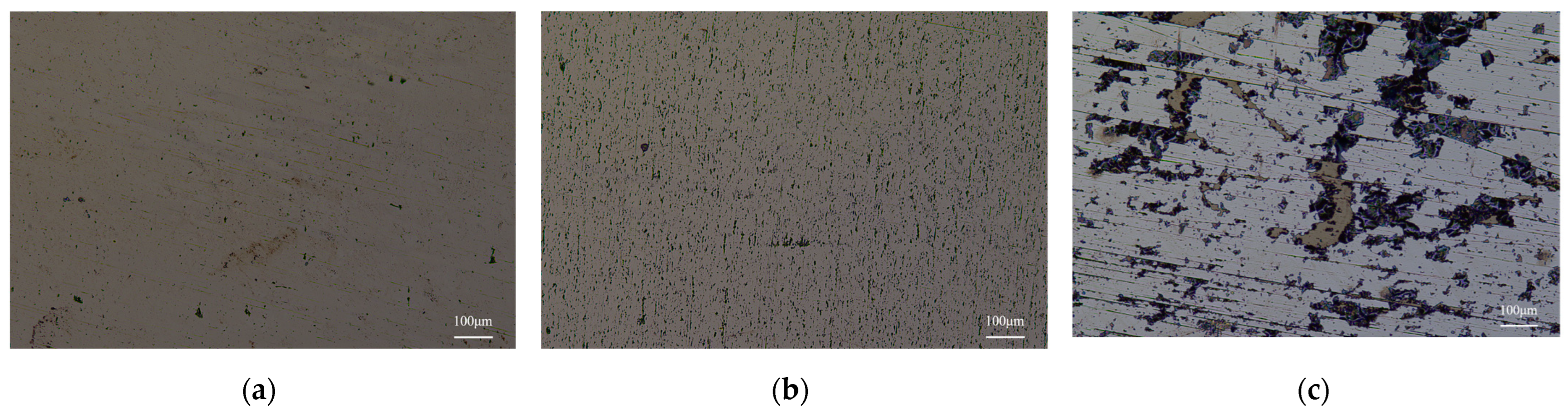
The surfaces of coatings were observed using an optical microscope, as shown in Figure 1. The TDCL and NDLC coatings presented with smooth and uniform surfaces. However, there was a mottled surface on the DLC coatings. Moreover, the DLC coatings could not effectively cover the surface of the substrate, and parts of the substrate were exposed. There were no doping elements or transition layer between the DLC coating and substrate. Due to the large difference in thermal expansion coefficient and high hardness gradient, the internal stress of the coating was so large that warping and peeling off occurred.
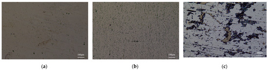
Figure 1.
Coating surface observed using an optical microscope: (a) NTDLC; (b) TDLC; (c) DLC.
3.1. Texture and Hardness
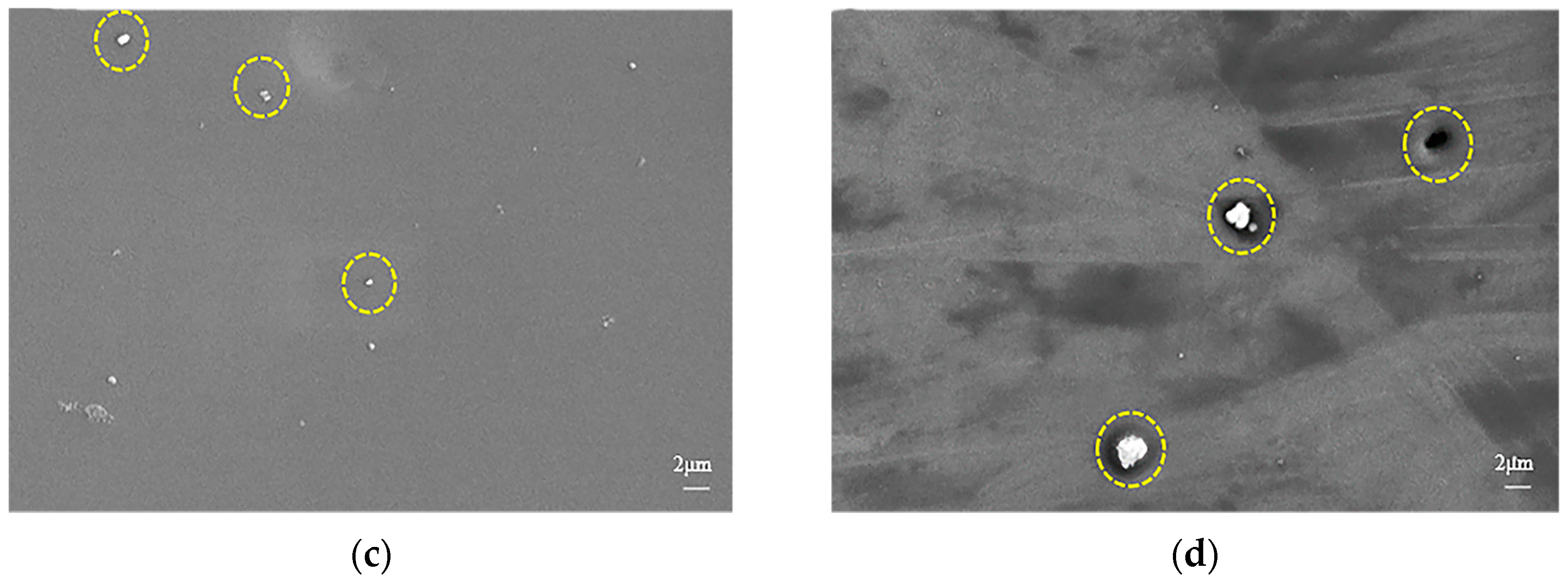
As shown in Figure 2, the cross-sections and morphology of the coatings were observed, and it was determined that the thicknesses of the coatings were approximately 245 nm. From the surface morphologies, micropores and particle aggregation were observed on the TDLC coating surface, while the NDLC surface was much smoother and denser. The micropores on the surface of the TDLC coating are pore defects generated during the deposition process. This also proves that the presence of doping elements has influence on the DLC forming process and Ni doping may decrease DLC surface defects.
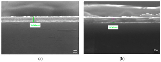

Figure 2.
Morphology and cross-section of the coating observed using SEM: (a) cross-section of NDLC; (b) cross-section of TDLC; (c) surface morphology of NDLC; (d) surface morphology of TDLC.
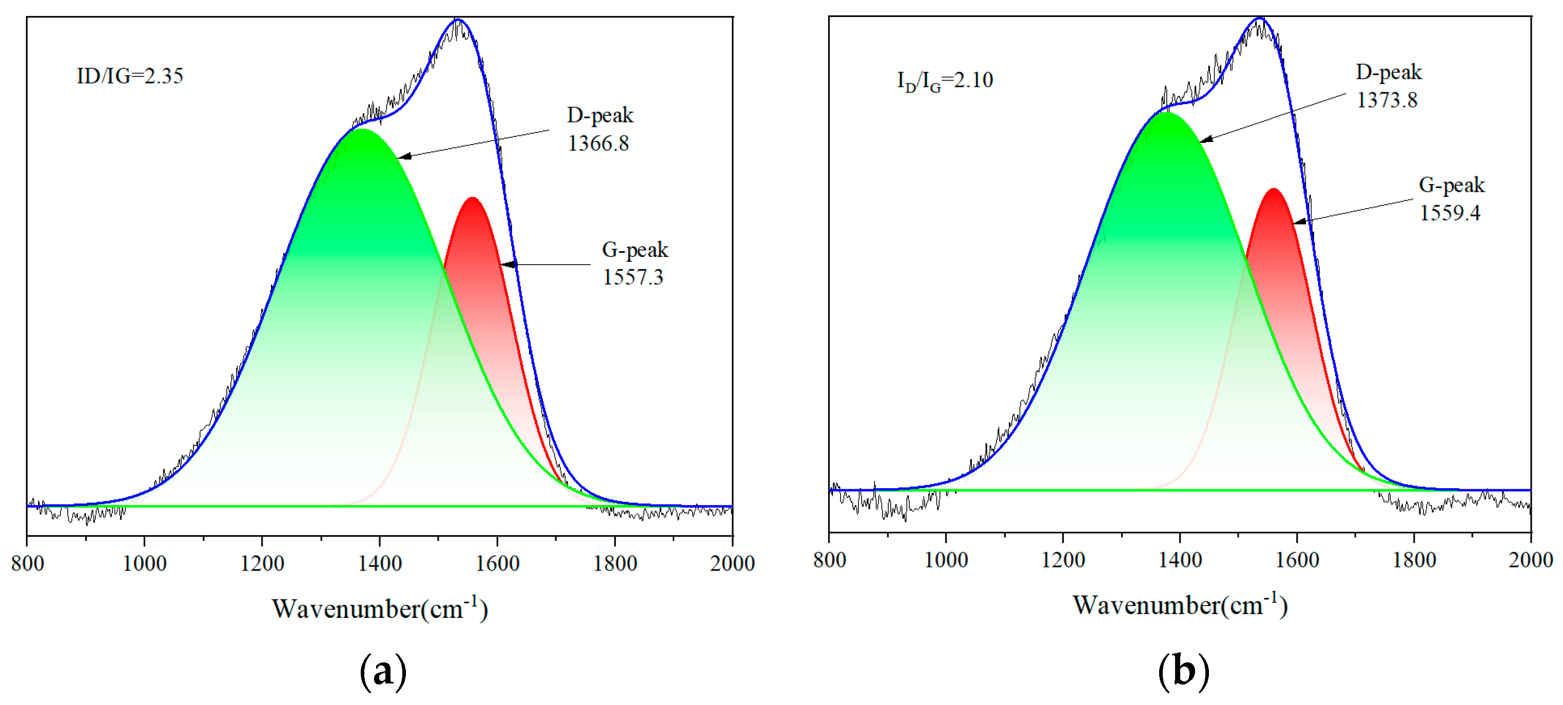
As detailed in Figure 3, the Raman spectra of the two coatings exhibit broad peaks at approximately 1350 cm−1 and 1550 cm−1, respectively, indicating that the coatings have a DLC structure hybridized with sp2-C and sp3-C. The peak at approximately 1350 cm−1 is referred to as peak D, which is related to the respiratory mode of sp2-C. The peak at approximately 1550 cm−1 is referred to the peak G, which is related to the tensile vibration mode of the chain or aromatic ring of sp3-C. Usually, the percentages of sp2-C and sp3-C are labeled ID and IG, respectively, and the ratio ID/IG represents their relative content [19]. Among those, the ID/IG values of the NDLC and the TDLC coatings were 2.35 and 2.10, respectively. The results indicate that sp2-C increased in the NDLC coating, while the percentage of sp3-C was higher in the TDLC coating. During the coating deposition process, the currents flowing into the Ni and Ti targets and their durations were exactly the same, suggesting that when compared with Ti, the addition of Ni promotes the formation of sp2-C in DLC coatings to a greater extent.
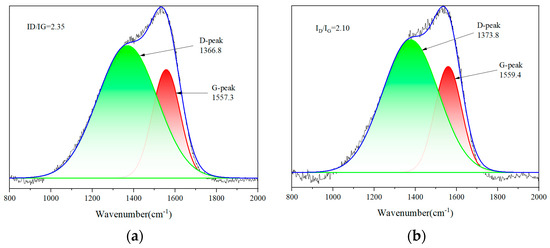
Figure 3.
Raman spectra of NDLC and TDLC coatings: (a) NDLC; (b) TDLC.
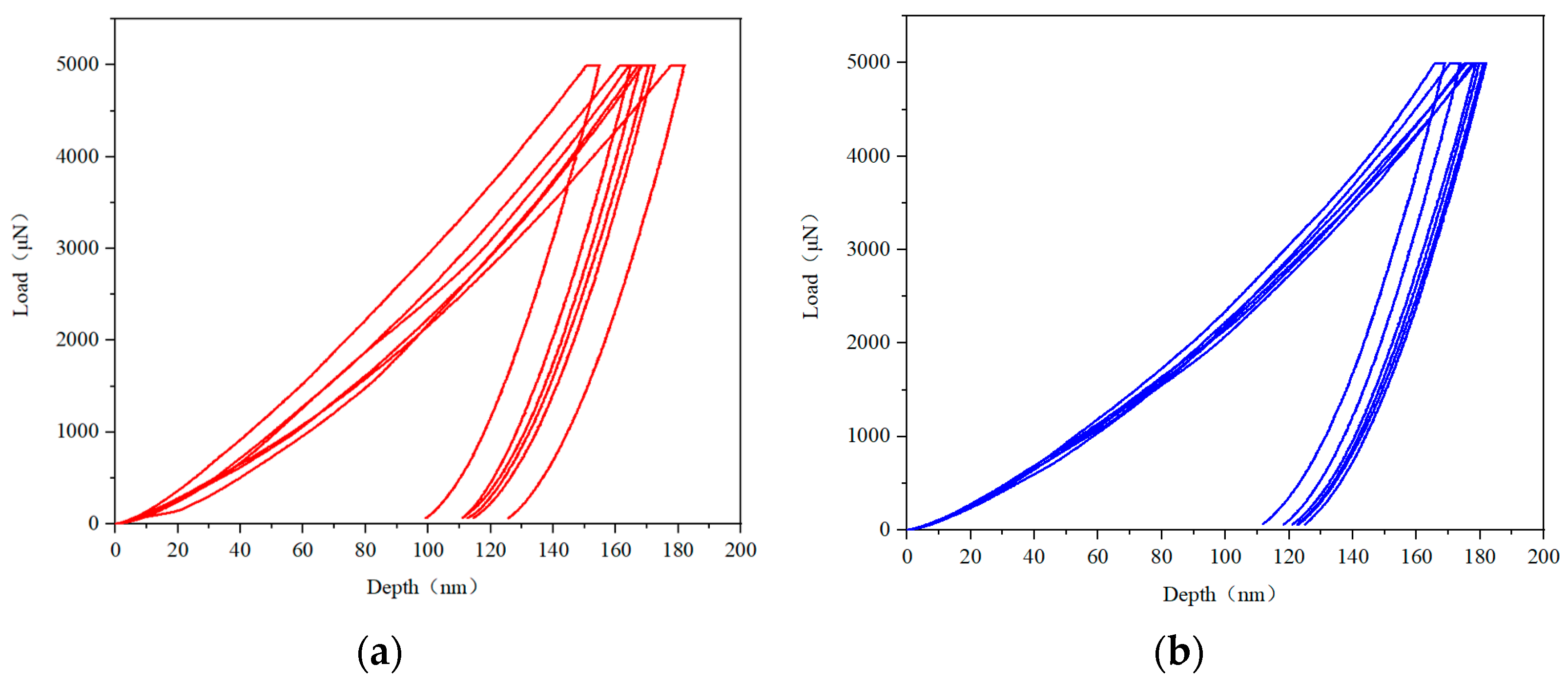
The depth–load curve of the nanoindentation is shown in Figure 4. It can be seen that under the same loading conditions, the penetration depth of the TDLC coating is greater. The analysis results confirm that under the same compression load, the smaller the depth, the greater the hardness. Therefore, the hardness of the NDLC coating was greater. The nanohardness, contact stiffness, and Young’s modulus of the coatings were calculated according to the indentation depth and load data, as shown in Figure 5. The average hardness of the NDLC coating was 7.53 GPa, and the average contact stiffness was 137.72 μN/nm. The average Young’s modulus was determined as 148.24 GPa. In comparison, the average hardness of the TDLC coating was 6.67 GPa, average contact stiffness was 135.63 μN/nm, and average Young’s modulus was 138.24 GPa. Obviously, the NDLC coatings have better mechanical properties.
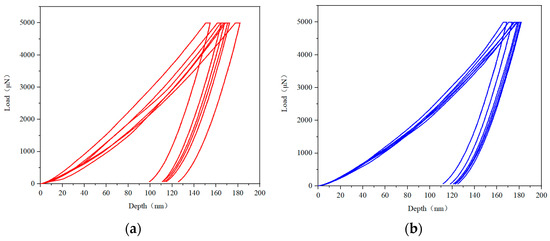
Figure 4.
Depth–load curves of nanoindentation: (a) NDLC; (b) TDLC.
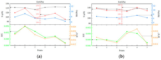
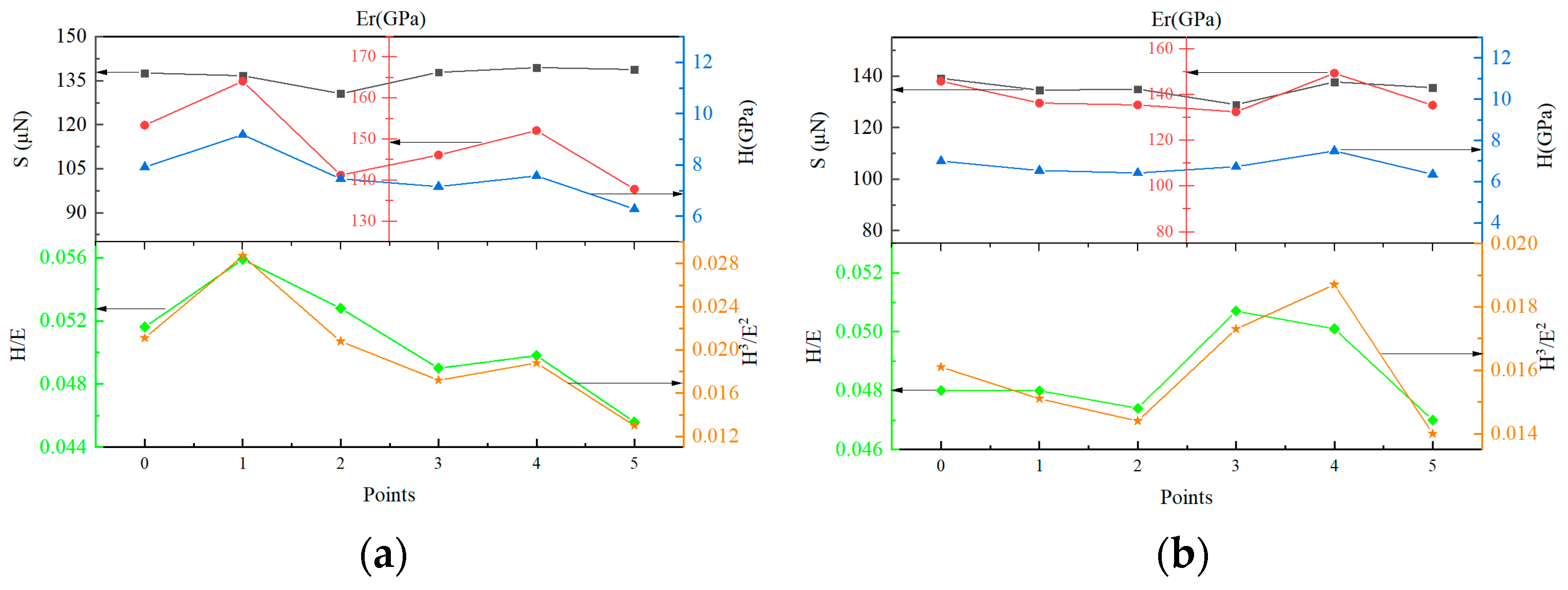
Figure 5.
Nanometer hardness (H), stiffness strength (S), Young’s modulus (Er), and variation curves of H/E and H3/E2 ratios of NDLC and TDLC coatings: (a) NDLC; (b) TDLC.
It is known that the hardness values are not necessarily the main parameters affecting the wear resistance and load bearing capacities. The ratio of material surface hardness to Young’s modulus (H/E) may be a more appropriate parameter for predicting wear resistance [20]. Therefore, the H/E and H3/E2 ratios of the two coatings were calculated separately, as shown in Figure 5. Figure 5a shows the H/E ratio and H3/E2 ratio of NDLC coatings, and Figure 5b presents the ratio of the TDLC coatings. Based on the average hardness and average Young’s modulus, we determined that the H/E was 0.0508 and the H3/E2 was 0.0194 for the NDLC coating. For the TDLC coating, the H/E was 0.0483 and the H3/E2 was 0.0155. These results indicate that the ratio of the NDLC was higher than that of the TDLC. It is suggested that the H/E is relevant to the fracture toughness of the coatings. Therefore, as an indicator of coating durability, this proves the higher failure bearing capacity of the NDLC coatings [21]. Meanwhile, the H3/E2 relates to plastic deformation. This proves that the wear resistance of the NDLC coating may be superior to that of the TDLC coating.
3.2. Adhesion and Tribological Behaviors
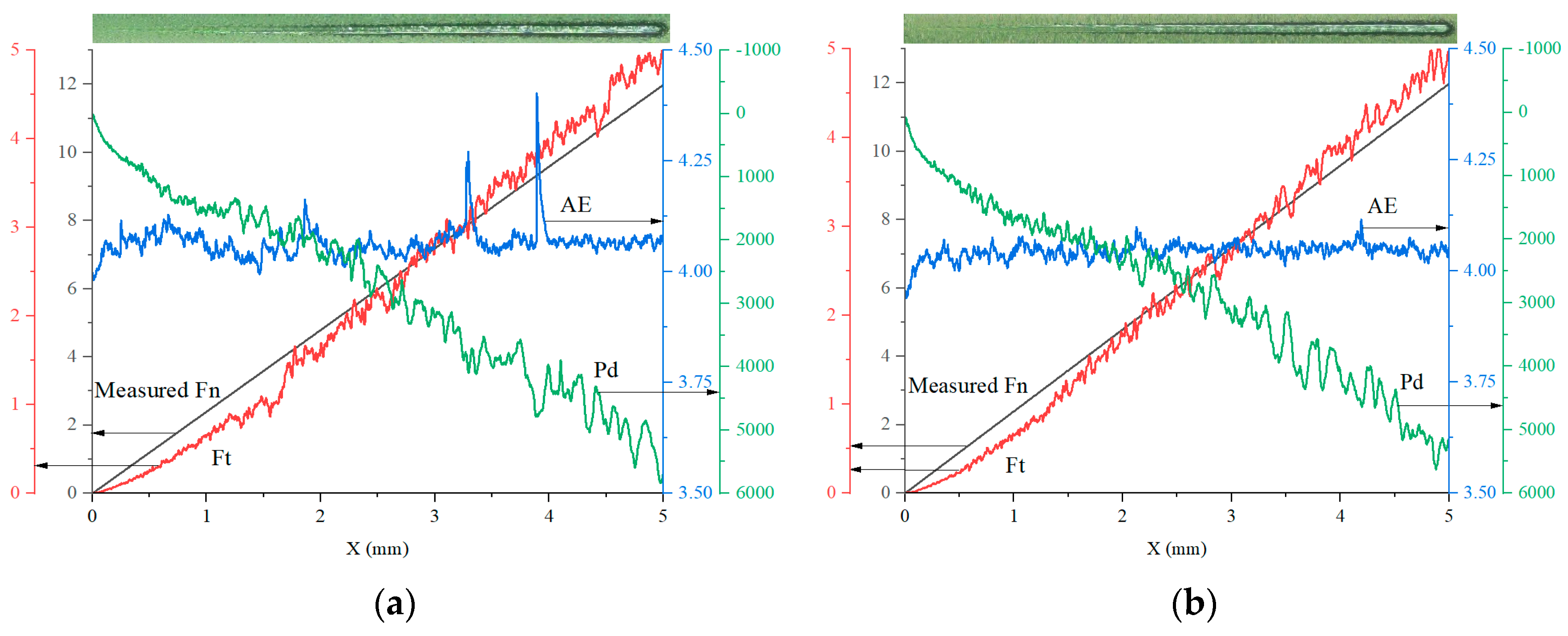
Nanoscratch tests were conducted to detect the adhesion between these thin coatings and the substrate, and the results are shown in Figure 6. It was observed that within one minute, the load increased evenly from 0 to 12 N, and the curvature radius of the scratch head was 100 μm. Five-millimeter-length scratches were created at a uniform speed. It can be observed from the microscopic images shown in Figure 6 that when transverse cracks appeared on both sides of the scratch, the coating became damaged and peeled off, and the corresponding critical load value was used as the bonding strength [22]. Subsequently, in order to avoid accidental situations, multiple scratches were made at different positions on the same sample along different directions. Then, the average critical bonding force was calculated. The average critical bonding forces of the NDLC and TDLC coatings were 3.51 N and 2.58 N, respectively, indicating that the Ni-doped NDLC coating has higher bonding strength between the coating and the substrate.
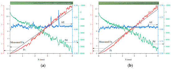
Figure 6.
Scratches of NDLC and TDLC: (a) NDLC; (b) TDLC.
The adhesion strength between the coatings and substrates was correlated to the structural mismatch, thermal expansion difference, and hardness gradients between them [23]. The results show that the pure Ti and Ni transition layers have similar hardness and, consequently, their abilities to reduce the hardness gradients of the coatings and substrates were similar. However, the presence of Ni in the NDLC coatings, which also were present in the 316 L substrate, induced the decrease in structural matching and thermal expansion difference. Thereby, the bonding force and surface appearance improved, as observed.
The friction coefficient curves of the 316 L stainless steel substrate and the different coating surfaces are shown in Figure 7. The average coefficient of friction (COF) of the substrate is 0.487. Notably, the average COF of the NDLC and TDLC coatings are 0.095 and 0.080, respectively. It can also be observed that the COF of NDLC gradually decrease but there are no regular fluctuations in TDLC friction progress. The COFs are both less than 0.1, which indicates that the presence of NDLC and TDLC coatings significantly reduce the COF.
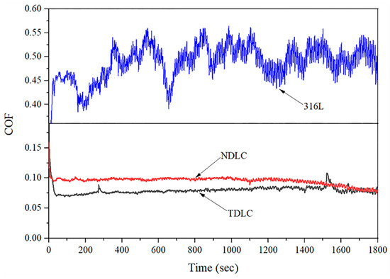
Figure 7.
316L stainless steel matrix and TDLC and NDLC friction coefficient curve.
Meanwhile, it was found that after thirty minutes of friction and wear testing, the surfaces of the substrates were severely worn, with deep wear scars. However, after the deposition of DLC coatings, the wear scars appeared to be shallower. Through optical microscope observations, the coatings were not completely worn, meaning that both coatings still worked to protect the substrate, and the wear scars of the NDLC coating were obviously narrower, indicating much harder coatings. After magnification was applied, it was observed that the NDLC coating had not peeled off to expose the substrate. However, as the friction test continued, a small number of white spots could be observed on the scar surfaces, indicating that the coating may have partially peeled off and exposed a small amount of stainless steel substrate. These results further confirm that the existence of NDLC coatings can not only effectively reduce the friction coefficient but also relatively improve wear resistance, thereby better protecting the substrate.
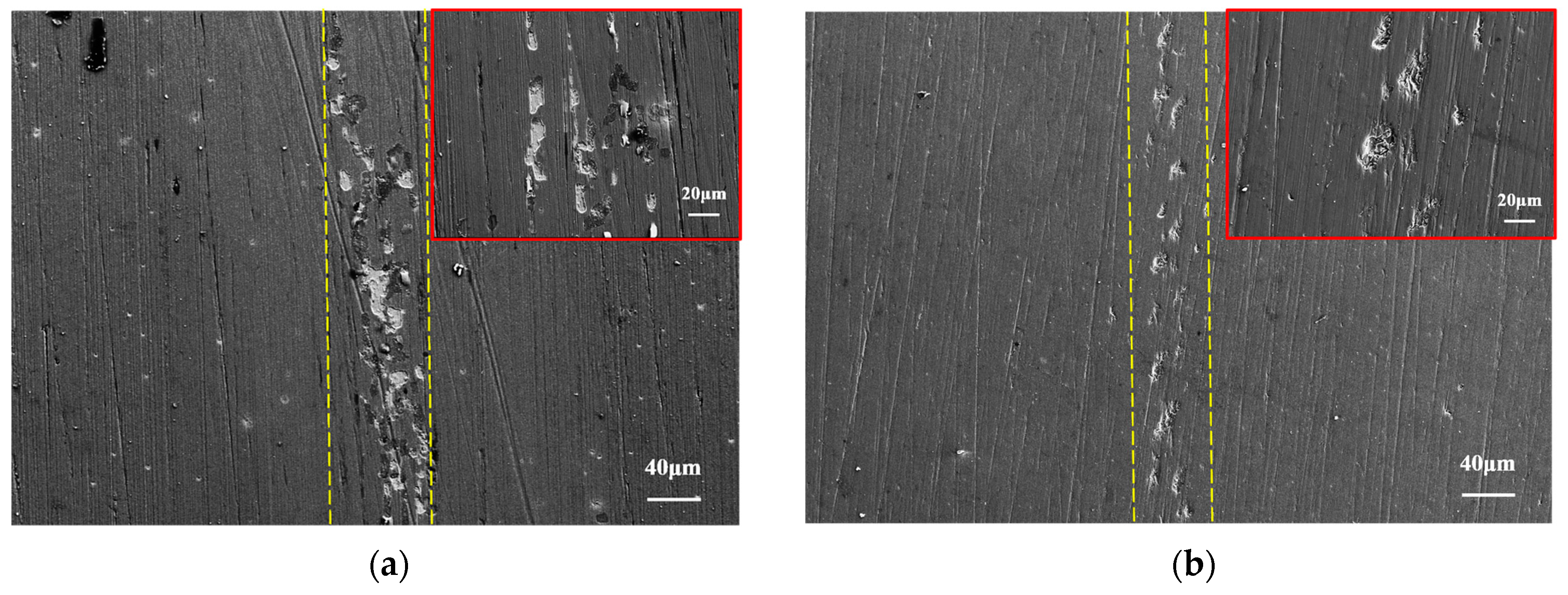
SEM observations of the wear scars revealed obvious cracks and delamination on the NDLC coating surfaces, as well as obvious pits and slight grooves in the TDLC coating wear scars. Therefore, it was concluded that the main abrasion mode was adhesive wear. It can be observed from Figure 8a that only the very thin outermost NDLC coatings adhered to the grinding ball, indicating that the inner coatings still adhere well to the substrate surface, resulting in the outer and partial coatings’ delamination and peeling off. As aforementioned, the hardness value of the NDLC coating was higher, and its bonding force between the coating and the substrate was also stronger, indicating that the NDLC coatings did not easily peel off or separate from the substrate during wear experiments. However, the hardness of the TDLC coating was found to be relatively low and the coatings that adhered to the surface of the grinding ball were transferred during the reciprocating abrasion processes. And, due to the weak adhesion force, larger particles were stripped from the coatings, forming many discontinuous pits. At the same time, abrasive wear was caused during the sliding abrasion processes since larger particles adhered to the surface of the grinding ball. The presence of those particles also led to fluctuations in the friction coefficient curves, as shown in Figure 8. Consequently, deeper furrows were formed and greater abrasion loss was observed on the surface of the TDLC coating.
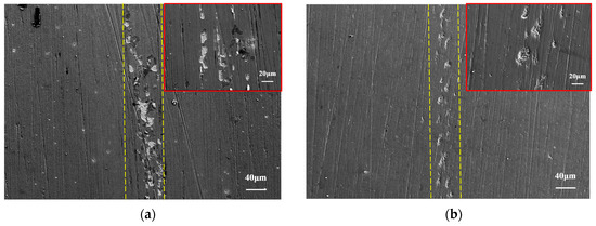
Figure 8.
COF curve of 316L stainless steel substrate with NDLC and TDLC coating and micromorphology of wear marks: (a) NDLC; (b) TDLC.
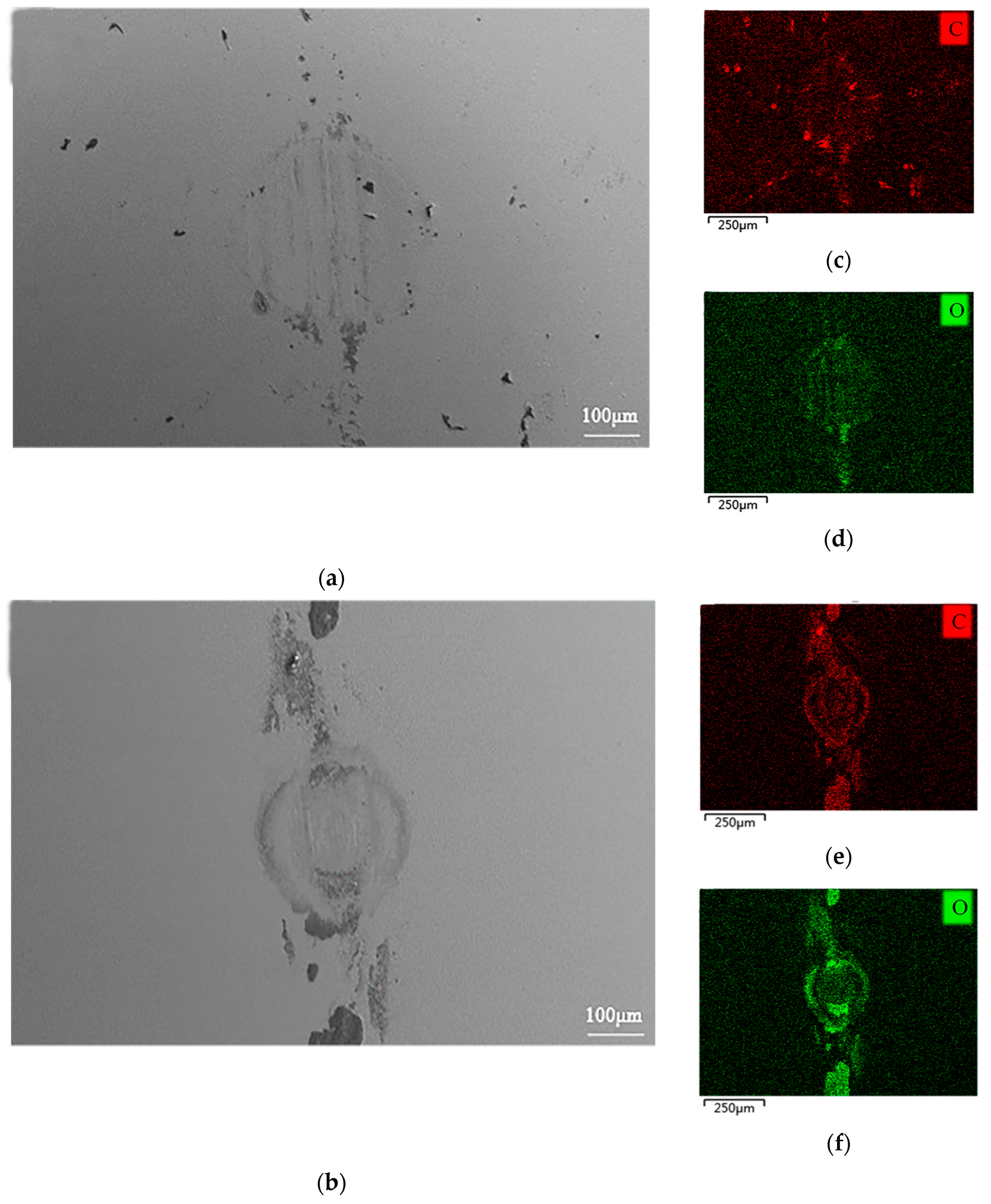
Through a comparison of the Raman, nanoindentation, and scratch observation results, it was perceived that the NDLC coating had a higher hardness value and stronger adhesion. Although its friction coefficient curve was slightly higher than that of the TDLC coating, it had better stability and wear resistance. Furthermore, the analysis results suggest that the sp2-C content in the NDLC coating was higher, which means that the graphite phase content was also higher. As graphitization occurs during the friction process, the graphitized film continues to transfer to the surface where it is uniformly distributed along the sliding direction [24]. A continuous graphitized layer is formed between the friction pairs [25] that causes a lubricating effect on the friction process, as shown in Figure 9. This leads to a gradual decrease in COF and further improves the wear resistance of the coatings [26]. However, it was found that the hardness and adhesion of the TDLC coating was relatively low, which led to the easy detachment of larger particles during friction and wear, which improved the COF and hindered the progress of the abrasion, resulting in unstable fluctuations in the COF curve.
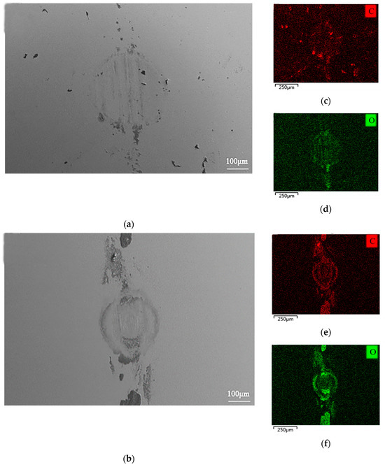
Figure 9.
SEM morphology and EDS analysis of the coating on the grinding ball: (a) grinding ball spot morphology of NDLC; (b) grinding ball spot morphology of TDLC; (c) C element in grinding ball spot of NDLC; (d) O element in grinding ball spot of NDLC; (e) C element in grinding ball spot of TDLC; (f) O element in grinding ball spot of TDLC.
4. Conclusions
Ti/Ni-doped DLC coatings were prepared using a DC magnetron sputtering method and the structure and properties of the DLC coatings were studied.
- (1)
- Ti/Ni doping can effectively improve the surface quality and interface bonding strength of DLC coatings. The Ni doping of DLC coatings had a compacted and smooth surface, with higher hardness values, elastic modulus, plastic toughness, and durability. The addition of Ni promoted the formation of sp2-C.
- (2)
- Both Ti and Ni doping can effectively improve the bonding force of DLC coatings. The presence of Ni in the substrate and Ni-containing coating makes for higher structural compatibility and improves binding strength.
- (3)
- The coating containing Ni achieved superior friction and wear performance. The Ni-doped DLC coating was observed as having a more stable friction coefficient, stronger wear resistance, and effectively suppressed oxidation corrosion at the friction interface.
Author Contributions
Conceptualization, B.Z.; Formal analysis, S.W.; Investigation, T.H.; Resources, F.G.; Writing—original draft, X.Y. and W.D.; Writing—review & editing, S.Z. All authors have read and agreed to the published version of the manuscript.
Funding
This research was funded by the National Natural Science Foundation of China grant number 51861031.
Institutional Review Board Statement
Not applicable.
Informed Consent Statement
Not applicable.
Data Availability Statement
Not applicable.
Conflicts of Interest
The authors declare no conflict of interest.
References
- Tillmann, W.; Dias, N.F.L.; Stangier, D.; Schaak, C.; Hoges, S. Coatability of diamond-like carbon on 316L stainless steel printed by binder jetting. Addit. Manuf. 2021, 44, 102064. [Google Scholar] [CrossRef]
- Carvalho, I.; Rodrigues, L.; Lima, M.J.; Carvalho, S.; Cruz, S.M.A. Overview on the Antimicrobial Activity and Biocompatibility of Sputtered Carbon-Based Coatings. Processes 2021, 9, 1428. [Google Scholar] [CrossRef]
- Zhou, Y.; Li, L.; Chen, Z.; Rao, L.; Yang, Q.J.D.; Materials, R. Accidental damaged diamond-like carbon coating by prefabricated scratches: Experimental exploration on anticorrosion and tribological performances. Diam. Relat. Mater 2020, 111, 108181. [Google Scholar] [CrossRef]
- Zhang, S.D.; Jiang, G.; Yang, Y.; Li, H.T.; Yan, F.Y.; Yan, M.F.; Zhang, Y.X. Annealing Effect on Microstructure of Novel Ti Doped DLC Multilayer Films. Coatings 2023, 13, 833. [Google Scholar] [CrossRef]
- Carmona, A.E.; Delfin, F.A.; Maskavizan, A.J.; Brühl, S.P. Análisis comparativo de recubrimientos duros de DLC y TiSiCN frente al desgaste y a la corrosión. Matéria 2023, 28, e20220312. [Google Scholar] [CrossRef]
- Duan, J.Q.; Li, M.H.; Wang, W.Z.; Huang, Z.M.; Jiang, H.; Ma, Y.P. Preparation and Performance of Multilayer Si-B-C-N/Diamond-like Carbon Gradient Films. Materials 2023, 16, 1665. [Google Scholar] [CrossRef]
- Zahid, R.; Masjuki, H.H.; Varman, M.; Mufti, R.A.; Kalam, M.A.; Gulzar, M. Effect of Lubricant Formulations on the Tribological Performance of Self-Mated Doped DLC Contacts: A review. Tribol. Lett. 2015, 58, 32. [Google Scholar] [CrossRef]
- Zeng, H.D.; Zhang, Y.W.; Wu, Z.; Qin, Z.B.; Ji, H.M.; Liu, X.J.; Li, B.Y.; Hu, W.B. Microstructure, magnetic properties and corrosion resistance of Co-DLC nanocomposite film controlled by substrate temperature. Diam. Relat. Mater. 2023, 133, 109673. [Google Scholar] [CrossRef]
- Wang, K.; Zhou, H.; Zhang, K.; Liu, X.; Zheng, Y.J.D.; Materials, R. Effects of Ti interlayer on adhesion property of DLC films: A first principle study. Diam. Relat. Mater 2021, 111, 108188. [Google Scholar] [CrossRef]
- Duminica, F.D.; Belchi, R.; Libralesso, L.; Mercier, D.J.S.; Technology, C. Investigation of Cr(N)/DLC multilayer coatings elaborated by PVD for high wear resistance and low friction applications. Surf. Coat. Technol. 2018, 337, 396–403. [Google Scholar] [CrossRef]
- Wang, H.; Qiu, Z.G.; Lin, S.S.; Xu, W.; Dai, M.J.; Su, Y.F. A Comparative Study of Copper-doped and Copper, Nitrogen Co-doped DLC Film Electrode and Its Electrochemical Properties. J. Electrochem. Soc. 2022, 169, 077503. [Google Scholar] [CrossRef]
- Evaristo, M.; Fernandes, F.; Cavaleiro, A. Influence of the alloying elements on the tribological performance of DLC coatings in different sliding conditions. Wear 2023, 526, 204880. [Google Scholar] [CrossRef]
- Ren, Z.C.; Chiang, R.; Qin, H.F.; Vasudevan, V.K.; Doll, G.L.; Dong, Y.L.; Ye, C. Tribological performance of 52,100 steel subjected to boron-doped DLC coating and ultrasonic nanocrystal surface modification. Wear 2020, 458, 203398. [Google Scholar] [CrossRef]
- Feng, L.M.; Hu, J.N.; Yan, S.; He, Z.Q.; Shi, J.J.; Li, J.Z. Effect of high-speed steel surface nitriding treatment on adhesion and wear resistance properties of nitrogen-doped diamond-like carbon coatings. Diam. Relat. Mater. 2023, 136, 110006. [Google Scholar] [CrossRef]
- Uzun, Y. Tribocorrosion properties of plasma nitrided, Ti-DLC coated and duplex surface treated AISI 316L stainless steel. Surf. Coat. Technol. 2022, 441, 128587. [Google Scholar] [CrossRef]
- Huang, L.; Yuan, J.T.; Li, C. Influence of titanium concentration on mechanical properties and wear resistance to Ti6Al4V of Ti-C:H on cemented carbide. Vacuum 2017, 138, 1–7. [Google Scholar] [CrossRef]
- Dovydaitis, V.; Marcinauskas, L.; Ayala, P.; Gnecco, E.; Zabels, R. The influence of Cr and Ni doping on the microstructure of oxygen containing diamond-like carbon films. Vacuum 2021, 191, 110351. [Google Scholar] [CrossRef]
- Suman, S.; Kumar, P.M.; Kumar, K.A. Nickel concentration dependent mechanical and tribological properties of subsurface layer of electrodeposited Ni-C nanocomposite thin films. Thin Solid Film. 2023, 773, 139818. [Google Scholar]
- Zhou, Y.F.; Li, L.L.; Shao, W.; Chen, Z.H.; Wang, S.F.; Xing, X.L.; Yang, Q.X. Mechanical and tribological behaviors of Ti-DLC films deposited on 304 stainless steel: Exploration with Ti doping from micro to macro. Diam. Relat. Mater. 2020, 107, 107870. [Google Scholar] [CrossRef]
- Caschera, D.; Federici, F.; Pandolfi, L.; Kaciulis, S.; Sebastiani, M.; Bemporad, E.; Padeletti, G. Effect of composition on mechanical behaviour of diamond-like carbon coatings modified with titanium. Thin Solid Film. 2011, 519, 3061–3067. [Google Scholar] [CrossRef]
- Charitidis, C.A. Nanomechanical and nanotribological properties of carbon-based thin films: A review. Int. J. Refract. Met. Hard Mater. 2010, 28, 51–70. [Google Scholar]
- Huang, P.K.; Yeh, J.W. Effects of nitrogen content on structure and mechanical properties of multi-element (AlCrNbSiTiV)N coating. Surf. Coat. Technol. 2009, 203, 1891–1896. [Google Scholar] [CrossRef]
- Kolawole, F.O.; Kolade, O.S.; Bello, S.A.; Kolawole, S.K.; Ayeni, A.T.; Elijah, T.F.; Borisade, S.G.; Tschiptschin, A.P. The improvement of diamond-like carbon coatings for tribological and tribo-corrosion applications in automobile engines: An updated review study. Int. J. Adv. Manuf. Technol. 2023, 126, 2295–2322. [Google Scholar] [CrossRef]
- Tian, J.; Chen, X.; Xu, J.; Yu, J.; Yu, Q.; Zhang, C.; Ma, L. Operando formation of multiphase heterostructure for achieving macroscale superlubricity with ultra-long lifetime under high contact stress. Mater. Today Chem. 2023, 28, 101363. [Google Scholar] [CrossRef]
- He, D.Q.; He, C.; Li, W.S.; Shang, L.L.; Wang, L.P.; Zhang, G.G. Tribological behaviors of in-situ textured DLC films under dry and lubricated conditions. Appl. Surf. Sci. 2020, 525, 146581. [Google Scholar] [CrossRef]
- Zhou, Y.F.; Chen, Z.H.; Zhang, T.; Zhang, S.L.; Xing, X.L.; Yang, Q.X.; Li, D.Y. Metastable hybridized structure transformation in amorphous carbon films during friction-A study combining experiments and MD simulation. Friction 2023, 11, 1708–1723. [Google Scholar] [CrossRef]


Disclaimer/Publisher’s Note: The statements, opinions and data contained in all publications are solely those of the individual author(s) and contributor(s) and not of MDPI and/or the editor(s). MDPI and/or the editor(s) disclaim responsibility for any injury to people or property resulting from any ideas, methods, instructions or products referred to in the content. |
© 2023 by the authors. Licensee MDPI, Basel, Switzerland. This article is an open access article distributed under the terms and conditions of the Creative Commons Attribution (CC BY) license (https://creativecommons.org/licenses/by/4.0/).