Abstract
In this work, the coatings obtained by a combined method, including Cr3C2-NiCr coating applied using a multichamber detonation device and subsequent pulse-plasma treatment, were investigated. This paper presents the results of an investigation of the influence of the pulse-plasma treatment (PPT) exposure distance on the structural-phase state of the surface layer of Cr3C2-NiCr-based detonation coatings. It was seen that after the PPT melting and alignment of the structural elements of coatings there were no signs of coating destruction from the impact of plasma pulses. It was established that the microstructure of the coatings was a molten metal–ceramic material based on Cr3C2-NiCr. It was also found that after pulse-plasma treatment, Cr2O3 chromium oxide phases are found on the surface, and the intensity of Cr3C2 peaks increased and new Cr3C2 reflexes appeared. It was further found that after pulse-plasma treatment the microstructure became more homogeneous, which led to the densification of the Cr3C2-NiCr-based detonation coating. It was established that the pulse-plasma treatment (PPT) contributed to increased hardness of the Cr3C2-NiCr coating material, from ~13.4 GPa (before PPT) to ~17.6 GPa (after PPT) and wear resistance twice that of the non-treated coating. The abrasive wear resistance and erosion resistance of Cr3C2-NiCr coatings were improved after pulse-plasma treatment.
1. Introduction
A current priority is to increase the reliability and durability of products whose performance is highly dependent on the properties and condition of their working surfaces. One of the ways to improve the performance characteristics and increase the service life of such products is the application of various technologies for applying functional coatings to the surfaces [1,2,3]. Taking into account the relatively high resistance to wear and corrosion of Cr3C2-NiCr metal–ceramic composition, these coatings have been widely used for the application of wear- and corrosion-resistant coatings on steel elements in the hot parts of waste-combustion boilers, as well as in electric furnaces and equipment operating on natural gas [4,5]. Metal–ceramic coatings of Cr3C2-NiCr system obtained by gas-thermal spraying methods are also used to reduce wear and protect against corrosion at high temperatures in parts of gas turbines operating under dry-friction conditions and used in various industries: electric power, oil refining, and the aerospace industry [5,6,7]. These ceramic–metal coatings are deposited using different gas-thermal spraying methods, such as plasma spraying, detonation spraying, and high-velocity gas-flame spraying (HVOF, HVAF) [8,9,10,11,12,13,14,15,16]. While the HVOF and HVAF methods produce high-quality Cr3C2-NiCr coatings, they do come with some drawbacks. The lower process temperatures and higher particle velocities result in a different chemical composition change, whereby carbide grains tend to bounce upon impact, thereby reducing the carbide content within the coating [6]. Studies [5,6] have also shown that both processes experience significant carbon loss and oxygen absorption, largely due to the water vapor generated during the combustion of hydrocarbon fuels, which act as a potent oxidizing agent [7]. Furthermore, the rapid cooling rates inherent in all sputtering processes lead to a metastable, non-equilibrium state of the coating. This coating gradually approaches a chemical composition equilibrium after deposition, but only through subsequent specialized treatments involving heating or high-temperature operations. The plasma-coating method achieves higher particle temperatures than the detonation method. The temperature limitations of the detonation method are compensated for by the higher kinetic energy of the particles, which make even refractory materials possible. Due to the high velocities at which the particles are applied with the detonation method, the coatings have a higher density (98–99%) and a stronger bond to the substrate than plasma coatings. The main advantage of the detonation method over gas-flame and plasma is its discrete nature, which results in less thermal stress. During the spraying process, parts can be heated to temperatures not exceeding 200 °C.
In [15], the corrosion behavior of Ni20Cr coatings obtained by detonation spraying (DS), high velocity gas plasma spraying (HVOF), and cold spraying methods was investigated. A comparative analysis of the three different coatings showed that detonation spraying proved to be better in terms of protection against hot corrosion failure. This may be due to the development of Cr2O3 protective phase, along with NiCr [17,18]. In addition, the coating obtained by the DS method was denser compared to cold spraying and HVOF. In [19], it was found that Cr3C2-NiCr coating obtained by the DS method significantly reduced the rate of erosion–corrosion processes and oxidation, compared to coatings obtained by the HVOF method. Enhancing the quality attributes of gas-thermal coatings is attainable through the application of high-energy external influences [20,21]. The most efficient approach involves a comprehensive pulse-plasma treatment, which encompasses surface modification through the use of magnetic fields, electrical current (comprising charged elementary particles), and a high-gradient thermal jet (plasma) that incorporates both metallic and nonmetallic alloying components [21,22,23]. In this case, the possibility of an optimal combination of properties of different areas of coatings, corresponding to the functional purpose of the applied materials, was achieved. At the same time, the obtaining technology has prospects for development with improvement of the properties of the applied materials by treatment with highly concentrated energy streams. For example, layer-by-layer processing of sprayed wear-resistant materials by pulses of high-energy plasma streams with different energy levels creates prerequisites for obtaining structures with adjustable porosity decreasing from the outer layers of coatings to the substrate. It will allow increased oil-holding capacity and wear resistance of friction surfaces in combination with increased cohesive and adhesive strength of the boundary layers. To realize the prospects of this processing it is necessary to study its peculiarities and to solve the following main task: to optimize the regimes of influence of high-energy plasma flows on gas-thermal coatings. Taking this into account, the criterion for optimization of pulse-plasma treatment of Cr3C2-NiCr coatings is the maximum temperature of their melting and densification, which is achieved by varying the exposure distance. At the same time, the reduction of the distance is limited by the appearance of signs of coating failure (e.g., cracks developing). The aim of this work was to study the influence of the exposure distance of pulse-plasma treatment on the structure and property of detonation coatings based on Cr3C2-NiCr.
2. Materials and Methods
Cr3C2-NiCr powder (75/25), with a particle diameter in the range of 10 to 45 microns (supplied by H.C. Starck under the name AMPERIT® 584.054) was used to create coatings on 12X1MF steel samples. The coatings were deposited using the detonation sputtering (DS) method in a dedicated multichamber setup as described in the source [24]. To achieve important characteristics such as pressure and velocity, the combustion products of the gas mixture were subjected to a detonation-combustion process in specially profiled chambers, and then the energy from this process was stored in the cylindrical barrel of the machine [25]. This system created a stream of combustion products that was used to accelerate and heat the powder, which is then applied to create high-quality metal and ceramic coatings [24,25].
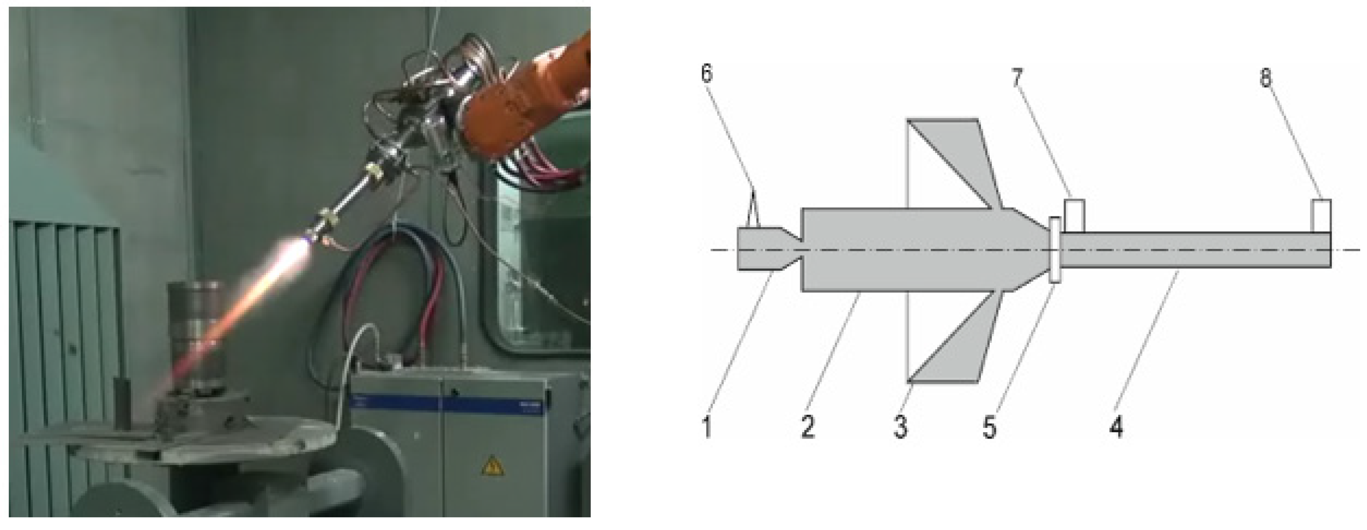
Figure 1 shows a schematic of a multichamber detonation apparatus developed at the E.O. Paton Institute of Electrical Welding of the National Academy of Sciences of Ukraine. This apparatus comprised three chambers: 1—a forechamber designed for initiating the detonation process; 2—the primary cylindrical chamber where the detonation combustion regime takes place; 3—an annular hemispherical chamber featuring a slotted outlet leading to a conoidal chamber that is coaxial with the barrel. The acceleration and heating of the powder charge occurred within the cylindrical barrel; 4—the powder was metered and supplied through the annular slot; 5—detonation initiation was performed using an automotive spark plug; 6—the pressure and velocity of the combustion products were monitored by pressure sensors positioned at both ends of the barrel; 7 and 8—the hemispherical chamber facilitated the detonation regime within angular concentrators, significantly enhancing the speed and completeness of combustion of the combustible mixture components. The combustion products from these chambers were collected, resulting in high pressure and temperature. Ultimately, this yielded high velocity and sufficiently elevated temperatures, enabling the application of ceramic coatings through spraying [25].
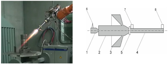
Figure 1.
General view and scheme of detonation device. 1—forechamber; 2—the primary cylindrical chamber; 3—annular hemispherical chamber; 4—barrel; 5—annular slot; 6—candle for detonation initiation; 7, 8—pressure sensors.
The design characteristics of the multichamber detonation device enabled the achievement of detonation combustion for mixtures with a low content of combustible components while maintaining the temperature of the combustion products. To accelerate and heat the powder, the specified dosage was directed into the inner barrel, which had a diameter of 16/18 mm and a length of 300/500 mm, chosen based on the properties of the material to be coated. In front of the barrel nozzle there was an annular hemispherical and cylindrical chamber that significantly elevated the pressure (up to 40 atmospheres) and the density of the combustion products. This effectively accelerated and heated the introduced powder, which was fed through an annular slit via a specialized gas-dynamic dosing device for pulse delivery of a compact gas–powder mixture dose. The initiation of detonation combustion for the gas mixture was carried out using an automotive spark plug, with a detonation frequency of 20 Hz or higher. Gases and powder were continuously supplied to the device using a standard powder-feeding system, with a powder-flow rate of 0.9 kg/h or higher. Dosing of gases and powder, as well as their introduction into the device, were managed by gas-dynamic devices that harnessed the energy of combustion products to perform these operations (Table 1).

Table 1.
Quantitative consumption of combustible mixture constituents in a detonation device.
Pulse-plasma treatment (PPT) was used to change the surface of the coating obtained by detonation spraying. Formation of high-energy pulses was carried out in a plasmatron by creating unsteady detonation regimes of combustible gas mixtures (C3H8 and O2) burning between two coaxial electrodes. The energy parameters of the unsteady detonation combustion products (pulse-plasma jet) were determined by solving the two-dimensional unsteady detonation wave (DW) propagation problem in the electric field between two coaxial electrodes of the plasmatron. Figure 2 depicts a pulsed plasmatron comprising a detonation chamber (1) in which the combustible gas mixture was generated and its detonation combustion was initiated. The plasmatron had a central electrode—anode 3, a conical electrode—cathode 4, and a vaporizable electrode 5. The electrodes were included in an electric circuit to a special power supply 2. When the detonation was initiated, combustion products flowed from the detonation chamber into the interelectrode gap 4 and close the electric circuit. The stationary detonation combustion of combustible gases changes to unsteady detonation combustion, which received additional energy through the electrically conductive layer of combustion products. When the plasma jet was expelled from the plasmatron, it completed the electrical circuit between the anode electrode and the product surface acting as the cathode 7.
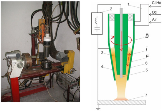
Figure 2.
General view and schematic diagram of the pulse-plasma device scheme of detonation device. 1—detonation chamber, 2—power supply, 3, 4—coaxial electrodes, 5—eroded electrode, 6—plasma, 7—product.
Parameters of pulse-plasma treatment are given in Table 2.
Table 2.
Pulse-plasma treatment parameters.
When subjected to an electric field with an intensity of 3.5 × 10⁵ V/m between the electrodes, the plasma emitted from the plasmatron reached a velocity of 4 km/s and a temperature of 12,000 K. Upon interaction with the product’s surface, this plasma pulse created a region of shock-compressed plasma layer, effectively closing the electrical circuit between the eroding electrode and the product, resulting in a current density of 10 kA/cm2. This exposure subjected the surface to repeated pulses of electric current, magnetic fields, and high thermal energy from the plasma, with a heat flux power density ranging between 104 and 106 W/cm2. Pulse plasma can be generated at frequencies ranging from 1 to 4 Hz, with energy levels reaching up to 7 kJ. To analyze the phase composition of the DS and DS/PPT coatings, X-ray diffraction analysis was conducted using an X-ray diffractometer X’PertPRO from Philips Corporation in Amsterdam, Netherlands. Cu-Kα radiation (λ = 2.2897 Å) was employed with a voltage of 40 kV and a current of 30 mA. The diffractograms were interpreted using the HighScore program. Measurements were taken within a range of angles from 2θ, starting from 200 to 900, with a step of 0.02 and a counting time of 0.5 s at each step.
For the examination of the surface morphology of the coatings, backscattered electron microscopy (BSE) scanning electron microscopy (SEM) was employed, utilizing a Tescan scanning electron microscope from Brno, Czech Republic. Micrographs of the coating surface were acquired using an Altami MET 5S model metallographic microscope from Altami LLC in St. Petersburg, Russia. The surface roughness of the coatings was assessed with a model 130 profilometer from JSC “Plant PROTON” in Moscow, Russia. The hardness of the sample cross-sections was measured using the nanoindentation method on a NanoScan-4D nanohardness meter (FSBU TISNCM, Moscow, Russia) following GOST R8.748-2011, utilizing a Berkovich indenter for 15 indentations at a load of 100 mN. To measure the hardness of the sample cross-sections, the nanoindentation method was employed using a NanoScan-4D nanohardness tester. The measurements were conducted in accordance with the GOST R8.748-2011 standard, employing a Berkovich indenter with 15 indentations at a load of 100 millinewtons. Tribological sliding tests were carried out using a TRB3 (Anton Paar Srl, Peseux, Switzerland) tribometer, employing the standard “ball-disk” technique (following international standards ASTM G 133-95 and ASTM G99). In this experiment, a 6.0 mm diameter ball made of SiC-coated steel served as the counterbody. The load applied was 6 N, with a sliding velocity of 15 cm/sec, a wear-curvature radius of 5 mm, and a friction path of 1200 m. The study of abrasive wear was conducted using an experimental setup whereby abrasive particles were rigidly fixed and followed the “rotating roller—flat surface” scheme, in line with the standard GOST 23.208-79 [26], similar to the American standard ASTM C 6568. After each test, the mass loss of the specimens was measured, and the average loss value was determined, accounting for standard deviation. Experiments to assess room-temperature erosion resistance were carried out using a specialized apparatus in accordance with ASTM G76-04 [27]. In this test, a nozzle tube with a diameter of 3 mm was positioned at a distance of 10 mm from the sample. The nozzle was inclined at a 90-degree angle relative to the specimen, and quartz with a grain size of 50 μm was used as the abrasive. The test duration was 5 min.
3. Results and Discussion
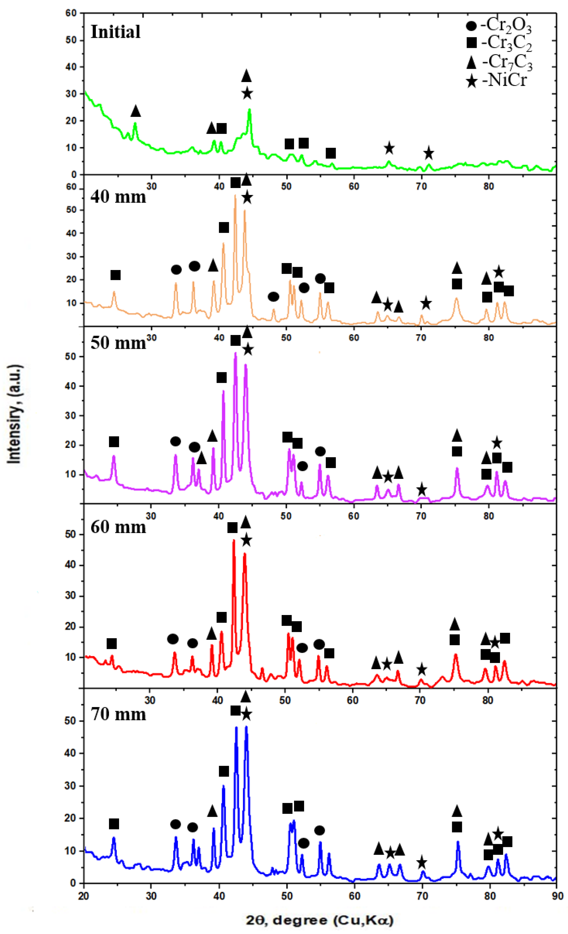
Figure 3 shows the diffractograms of the coating surface before (DS) and after pulse-plasma treatment (DS/RRT). The following phases were detected in the coatings before pulse-plasma treatment: NiCr, Cr3C2, and Cr7C3 (see Figure 3). Chromium and nickel formed a eutectic-type state diagram with a eutectic-equilibrium temperature of 1345 °C. Despite the atomic radii of chromium and nickel being close (rCr = 0.127 nm, rNi = 0.124 nm), due to the nonisomorphism of their lattices (Cr-OCC, Ni-HCC) they form limited solid solutions: γ—on the basis of nickel and α—solid solution on the basis of chromium. After the pulse-plasma treatment, Cr2O3 chromium oxide phases were detected on the surface (see Figure 3). It is noticeable that after the pulse-plasma treatment, an increase in the intensity of the Cr3C2 chromium carbide peaks was observed and many new peaks associated with this phase were detected in the diffractogram. This was due to the short-term activation of the coating surface under the influence of pulse plasma, in which active carbon and oxygen were present. This contributed to the simultaneous occurrence of two competing chemical–thermal processes—oxidation and carburisation. The combination of solid phases of chromium oxide and carbide in the hardened-metal matrix significantly improved the resistance of the obtained material to abrasive wear. It is noticeable that a significant increase in the intensity of Cr3C2 and Cr2O3 chromium carbide peaks was observed at a distance of 40 mm, while a decrease in the intensity of Cr3C2 and Cr2O3 peaks was observed at a distance of 70 mm.
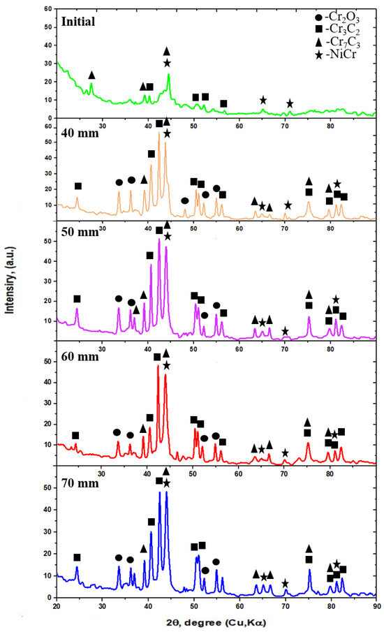
Figure 3.
X-ray radiographs of the Cr3C2-NiCr coating material surface before and after pulse-plasma treatment.
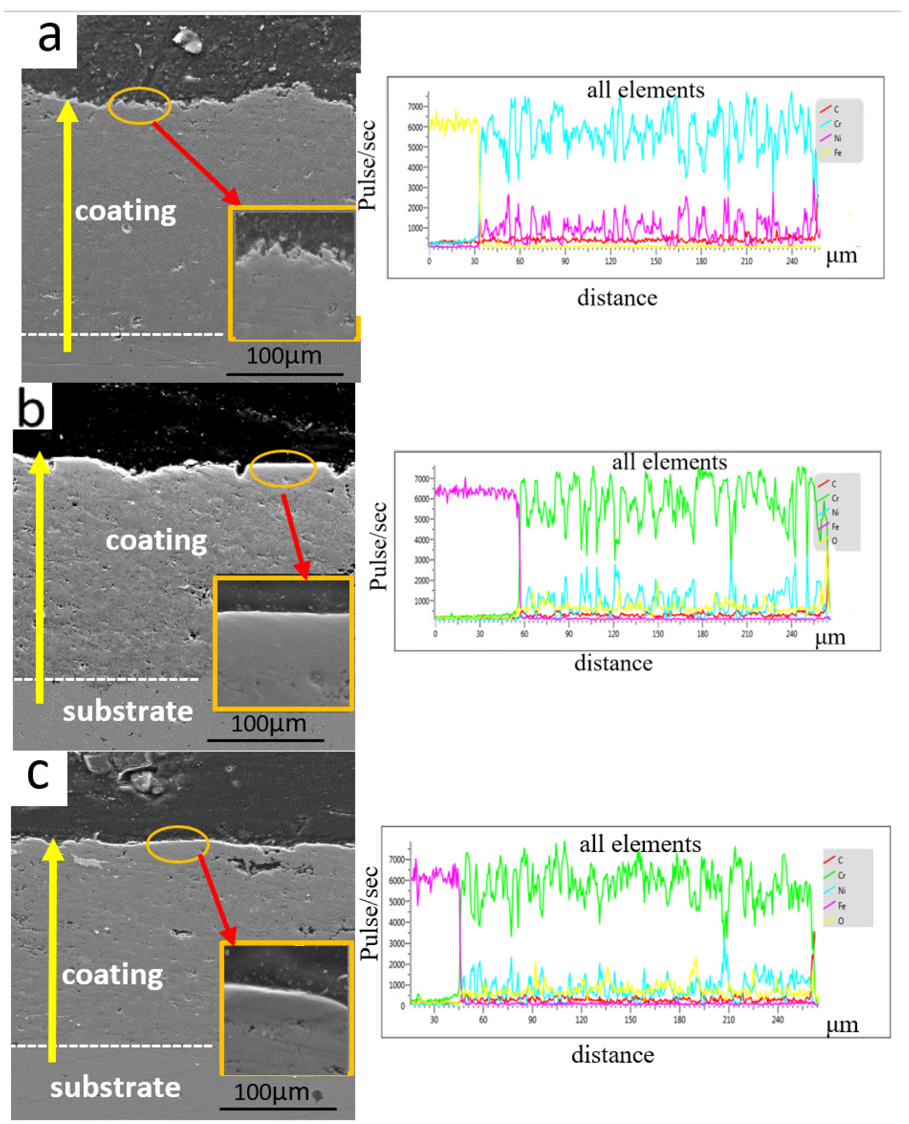
The cross-sectional microstructure of the coatings obtained through the pulse-plasma treatment process at different distances between the plasma torch and the treated surface is shown in Figure 4. We analyzed the surface morphology by scanning electron microscopy (SEM) using backscattered electrons (SE) on a scanning electron microscope. The initial surface condition prior to pulse-plasma treatment (Figure 4a) showed characteristic features of a porous structure typical of detonation sputtering, with some medium defects located closer to the coating surface. After the application of pulse-plasma treatment, there was a marked decrease in the number of pores in the subsurface of the coating, leading to minimum values, due to the melting of the boundaries of the large defects (this is indicated by the arrows in the enlarged sections in Figure 4b). At a distance of 40 mm, the microstructure of the coatings became more homogeneous and the porosity, as well as the number of particles cut out during sample fabrication, decreased (see Figure 4b). However, the coating processed at 70 mm still had high porosity compared to the other modes. Based on these data, it can be concluded that the use of pulse-plasma treatment at a distance of 40 mm is optimal.
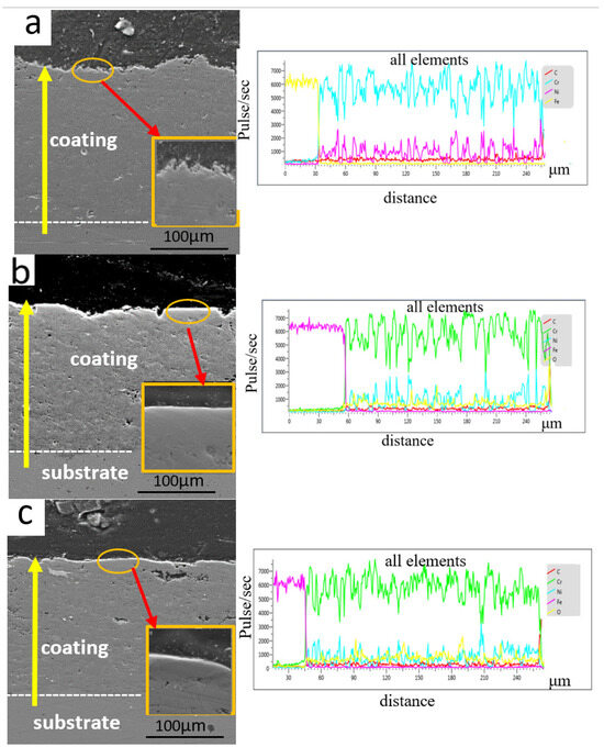
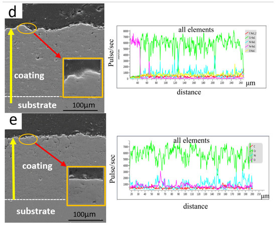
Figure 4.
Coating structure before (a) and after PPT (b) 40 mm, (c) 50 mm, (d) 60 mm, (e) 70 mm.
We used the nanoindentation method to measure the hardness of Cr3C2-NiCr detonation coatings before and after pulse-plasma treatment. The results of the hardness measurements are shown in Figure 5. After undergoing pulse-plasma treatment, the hardness of the coatings increased significantly compared to the initial state. The hardness value of the coatings depended on the distance at which the treatment was carried out. The highest hardness was observed after pulse-plasma treatment at a distance of 40 mm, and it is about 17.6 GPa. As the distance between the plasma gun and the treated surface increased, the hardness gradually decreased. This phenomenon may be due to the different degree of localized melting of the material, which depends on the distance of the exposure to the pulsed plasma.
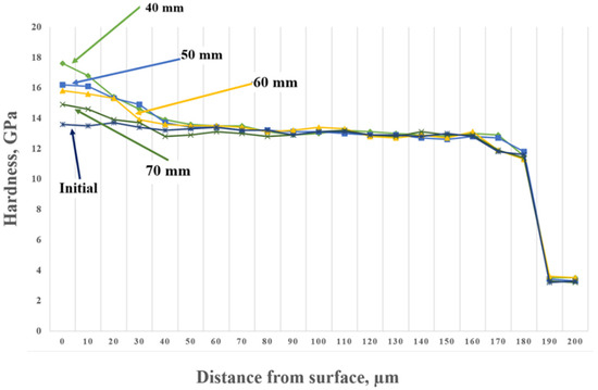
Figure 5.
Hardness and depth distribution graph of Cr3C2-NiCr coatings before and after PPT.
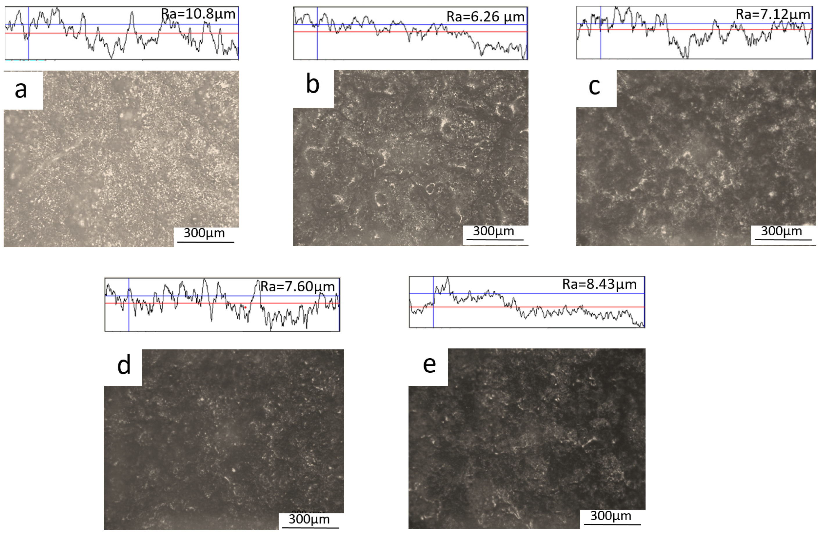
Figure 6 shows the results of surface-roughness measurements of the material coated with Cr3C2-NiCr-based coatings. These measurements revealed the inhomogeneous surface structure with the presence of pores. The main parameter used to evaluate the roughness was the Ra value, which is the arithmetic mean deviation of the surface profile. The value of surface roughness was found to be dependent on the distance at which the pulse-plasma treatment was carried out. The lowest roughness was found after machining at a distance of 40 mm (see Figure 6b). This roughness reduction was about 42% compared to the initial surface roughness parameters before the pulse-plasma treatment. At other distances, a roughness reduction was also observed (see Figure 6c–e). This process of roughness reduction is related to the melting of protruding fragments and pores on the coating surface caused by the pulse-plasma exposure, which contributed to the improvement of roughness parameters.
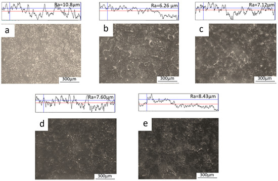
Figure 6.
Relief images and surface roughness of Cr3C2 coatings before (a) and after (b) 40 mm, (c) 50 mm, (d) 60 mm, (e) 70 mm pulse-plasma processing.
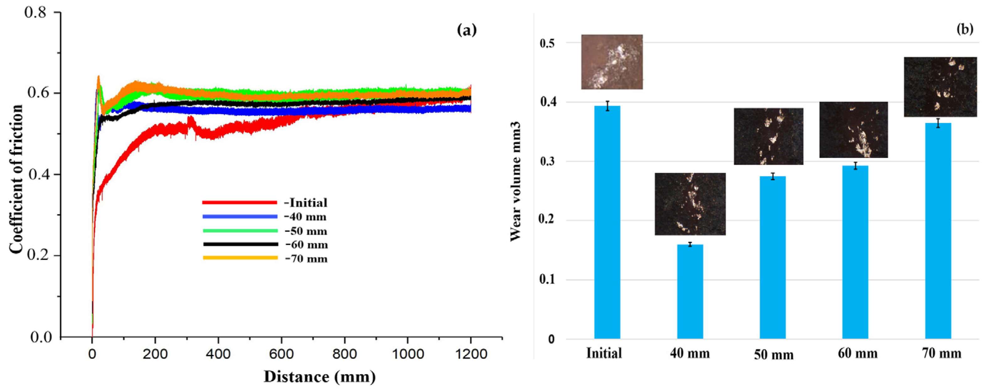
One of the key factors influencing the longevity of products lies in their tribological properties. In this research, we assessed the wear characteristics of coatings both before and after pulse-plasma treatment using the ball-disk method (Figure 7a). Profilograms were generated from the profilometer data, and wear volumes were computed before and after treatment with specialized software. The test outcomes revealed that the coating’s resistance to wear significantly improved following pulse-plasma treatment. This finding aligns with XRD data and is likely attributable to the increased presence of the wear-resistant Cr3C2 carbide phase. The investigation of the coating’s tribological attributes also underscored the substantial impact of pulse-plasma treatment on the surface-friction coefficient and wear resistance. Post-treatment, the coating’s wear resistance nearly doubled in comparison to its initial values. It is worth noting that the level of wear resistance was contingent on the treatment distance. The highest degree of wear resistance was attained when the treatment was conducted at a distance of 40 mm from the surface, which can be regarded as the optimal distance.
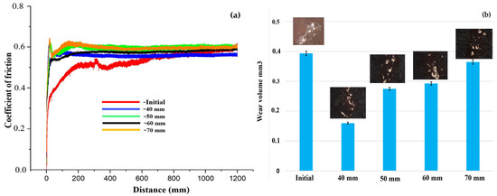
Figure 7.
Results of tribological tests of Cr3C2-NiCr coatings before (a) and after PPT (b).
To evaluate the resistance of Cr3C2-NiCr coatings before and after PPT to abrasive wear, tests were carried out on a special bench. After each experiment, we measured the mass loss of the samples and calculated the mean value accompanied by the standard deviation. The results of the abrasion tests are summarized in Table 3. It was found that the mass loss of the coating material after pulse-plasma treatment (PPT) was significantly 2–3 times less than that before treatment. This indicates the increased abrasion resistance of the material. This result can be explained by the presence of a higher content of the hardening carbide phase and solid chromium oxides in the coating material after the pulse-plasma treatment.
Table 3.
Abrasion and erosion wear results.
The results of these experiments, performed to evaluate the erosion wear, are presented in Table 3. These tests confirm that Cr3C2-NiCr coatings obtained using pulse-plasma treatment (PPT) significantly improved their resistance to the action of erosion particles. This result can also be explained by the fact that the coating material after IPP contains more hardening carbide phase and solid chromium oxides.
4. Conclusions
The impact of pulse-plasma treatment (PPT) distance on the structure and properties of Cr3C2-NiCr detonation coatings has been thoroughly investigated. From the analysis of our research findings, the following conclusions can be drawn: following PPT, the presence of chromium oxide phases, specifically Cr2O3, is detected on the surface. Additionally, the intensity of Cr3C2 peaks increased, and new Cr3C2 reflections emerged, indicating an enhanced content of the Cr3C2 phase; post-PPT observations revealed the melting and alignment of structural elements within the coatings, without any signs of coating deterioration due to plasma pulse impact. The microstructure of the coatings is characterized as a molten metal–ceramic material based on Cr3C2-NiCr; coatings treated at a distance of 40 mm exhibited minimal porosity in comparison to other PPT settings. The reduction in the roughness index resulted from the melting of protruding fragments and pores in the coating’s rough surface caused by pulse-plasma treatment; pulse-plasma treatment (PPT) led to a substantial increase in the hardness of the Cr3C2-NiCr coating material, elevating it from approximately 13.4 GPa (initial) to around 17.6 GPa, while simultaneously doubling its wear resistance compared to untreated coatings; both abrasive wear resistance and erosion resistance of Cr3C2-NiCr coatings were notably improved following pulse-plasma treatment; based on our findings, the optimal pulse-plasma treatment distance was determined to be 40 mm.
It is possible to recommend this combined method for coating, including detonation spraying and subsequent pulse-plasma treatment, as the optimal way to protect the surfaces of parts operating in extreme conditions of erosive and abrasive wear.
Author Contributions
D.K. and B.R. designed the experiments; B.R. and M.D. performed the experiments; D.K. and B.R. analyzed the data; L.S., D.K. and B.R. wrote, reviewed and edited the paper. All authors have read and agreed to the published version of the manuscript.
Funding
This research has been funded by the Science Committee of the Ministry of Science and Higher Education of the Republic of Kazakhstan (Grant no. AP09261164).
Data Availability Statement
Data is contained within the article.
Conflicts of Interest
The authors declare that there is no conflict of interest regarding the publication of this manuscript.
References
- Pogrebnyak, A.D.; Tyurin, Y.N. Modification of material properties and coating deposition using plasma jets. Phys.-Uspekhi 2005, 48, 487. [Google Scholar] [CrossRef]
- Lu, H.; Shang, J.; Jia, X.; Li, Y.; Li, F.; Li, J.; Nie, Y. Erosion and corrosion behavior of shrouded plasma sprayed Cr3C2-NiCr coating. Surf. Coat. Technol. 2020, 388, 125534. [Google Scholar] [CrossRef]
- Rubino, F.; Merino, D.; Silvestri, A.T.; Munez, C.; Poza, P. Mechanical properties optimization of Cr3C2-NiCr coatings produced by compact plasma spray process. Surf. Coat. Technol. 2023, 465, 129570. [Google Scholar] [CrossRef]
- Rakhadilov, B.; Kakimzhanov, D.; Dautbekov, M.; Sagdoldina, Z.; Adylkanova, M.; Abylkalykova, R. Influence of Spraying Parameters on the Structure and Tribological Properties of Cr3C2-NiCr Detonation Coatings. Adv. Tribol. 2023, 2023, 6684656. [Google Scholar] [CrossRef]
- Li, C.J.; Ji, G.C.; Wang, Y.Y.; Sonoya, K. Dominant effect of carbide rebounding on the carbon loss during high velocity oxy-fuel spraying of Cr3C2–NiCr. Thin Solid Films 2002, 419, 137–143. [Google Scholar] [CrossRef]
- Janka, L.; Norpoth, J.; Trache, R.; Berger, L.M. Influence of heat treatment on the abrasive wear resistance of a Cr3C2NiCr coating deposited by an ethene-fuelled HVOF spray process. Surf. Coat. Technol. 2016, 291, 444–451. [Google Scholar] [CrossRef]
- Matikainen, V.; Koivuluoto, H.; Vuoristo, P. A study of Cr3C2-based HVOF-and HVAF-sprayed coatings: Abrasion, dry particle erosion and cavitation erosion resistance. Wear 2020, 446, 203188. [Google Scholar] [CrossRef]
- Korpiola, K. High Temperature Oxidation of Metal, Alloy and Cermet Powders in HVOF Spraying Process; Helsinki University of Technology: Espoo, Finland, 2004. [Google Scholar]
- Rakhadilov, B.; Kakimzhanov, D.; Baizhan, D.; Muslimanova, G.; Pazylbek, S.; Zhurerova, L. Comparative study of structures and properties of detonation coatings with α-Al2O3 and γ-Al2O3 main phases. Coatings 2021, 11, 1566. [Google Scholar] [CrossRef]
- Roy, M. Dynamic hardness of detonation sprayed WC-Co coatings. J. Therm. Spray Technol. 2002, 11, 393–399. [Google Scholar] [CrossRef]
- Ulianitsky, V.Y.; Batraev, I.S.; Shtertser, A.A.; Dudina, D.V.; Bulina, N.V.; Smurov, I. Detonation spraying behaviour of refractory metals: Case studies for Mo and Ta-based powders. Adv. Powder Technol. 2018, 29, 1859–1864. [Google Scholar] [CrossRef]
- Ji, G.C.; Li, C.J.; Wang, Y.Y.; Li, W.Y. Microstructural characterization and abrasive wear performance of HVOF sprayed Cr3C2–NiCr coating. Surf. Coat. Technol. 2006, 200, 6749–6757. [Google Scholar] [CrossRef]
- Chatha, S.S.; Sidhu, H.S.; Sidhu, B.S. Characterisation and corrosion-erosion behaviour of carbide based thermal spray coatings. J. Miner. Mater. Charact. Eng. 2012, 11, 569. [Google Scholar] [CrossRef]
- Rakhadilov, B.; Kakimzhanov, D.; Buitkenov, D.; Abdulina, S.; Zhurerova, L.; Sagdoldina, Z. Structural Phase Transformations in Detonation Coatings Based on Ti3SiC2 after Pulse-Plasma Effect. Crystals 2022, 12, 1388. [Google Scholar] [CrossRef]
- Samodurova, M.; Shaburova, N.; Samoilova, O.; Moghaddam, A.O.; Pashkeev, K.; Ul’yanitckiy, V.; Trofimov, E. Properties of WC–10% Co–4% Cr detonation spray coating deposited on the Al–4% Cu–1% Mg alloy. Materials 2021, 14, 1206. [Google Scholar] [CrossRef] [PubMed]
- Xu, Q.; Wang, S.; Xu, C.; Chen, X.; Zeng, S.; Li, C.; Niu, Y. Synergistic effect of electrode defect regulation and Bi catalyst deposition on the performance of iron-chromium redox flow battery. Chin. Chem. Lett. 2023, 34, 108188. [Google Scholar] [CrossRef]
- Guilemany, J.M.; Espallargas, N.; Suegama, P.H.; Benedetti, A.V. Comparative study of Cr3C2–NiCr coatings obtained by HVOF and hard chromium coatings. Corros. Sci. 2006, 48, 2998–3013. [Google Scholar] [CrossRef]
- Muthu, S.M.; Arivarasu, M.; Arivazhagan, N. Investigation of hot corrosion resistance of bare and Ni-20% Cr coated superalloy 825 to Na2SO4-60% V2O5 environment at 900 °C. Procedia Struct. Integr. 2019, 14, 290–303. [Google Scholar] [CrossRef]
- Kamal, S.; Jayaganthan, R.; Prakash, S. Evaluation of cyclic hot corrosion behaviour of detonation gun sprayed Cr3C2–25% NiCr coatings on nickel-and iron-based superalloys. Surf. Coat. Technol. 2009, 203, 1004–1013. [Google Scholar] [CrossRef]
- Akamatsu, H.; Ikeda, T.; Azuma, K.; Fujiwara, E.; Yatsuzuka, M. Surface treatment of steel by short pulsed injection of high-power ion beam. Surf. Coat. Technol. 2001, 136, 269–272. [Google Scholar] [CrossRef]
- Tyurin, Y.N.; Zhadkevich, M.L. Plasma hardening technologies. Nauk. Dumka 2008, 218, 16–21. (In Russian) [Google Scholar]
- Kukudzhanov, K.V. Processes of healing of microcracks in metal under the action of high-density current pulses. Probl. Strength Plast. 2016, 78, 300–310. (In Russian) [Google Scholar]
- Rakhadilov, B.K.; Tyurin, Y.; Kakimzhanov, D.; Baizhan, D.; Kolisnichenko, O.; Zhurerova, L. Deposition of duplex Cr3C2-NiCr coatings on steel using a combined technique of gas detonation spraying and pulse-plasma treatment. High Temp. Mater. Process. Int. Q. High-Technol. Plasma Process. 2021, 25, 25–37. [Google Scholar] [CrossRef]
- Kolisnichenko, O.V.; Tyurin, Y.N.; Tovbin, R. Efficiency of the process of coating spraying using a multichamber detonation device. Autom. Weld. 2017, 10, 28–34. [Google Scholar]
- Markashova, L.I.; Tyurin, Y.N.; Kolisnichenko, O.V.; Valevich, M.L.; Bogachev, D.G. Structure-phase state of wear-resistant composite coatings of the Cr3C2-NiCr system applied using a multi-chamber detonation unit. Proc. Math. Model. Inf. Technol. Weld. Relat. Process. 2014, 37, 103–107. (In Russian) [Google Scholar]
- GOST 23.207-79; Ensuring of Wear Resistance of Products. Testing of Engineering Materials for Impact Abrasive Wear. 1979. Available online: http://vsegost.com/Catalog/43/4374.shtml (accessed on 31 August 2022).
- ASTM G76-04; Standard Test Method for Conducting Erosion Tests by Solid Particle Impingement Using Gas Jets. ASTM International: West Conshohocken, PA, USA, 2004.


Disclaimer/Publisher’s Note: The statements, opinions and data contained in all publications are solely those of the individual author(s) and contributor(s) and not of MDPI and/or the editor(s). MDPI and/or the editor(s) disclaim responsibility for any injury to people or property resulting from any ideas, methods, instructions or products referred to in the content. |
© 2023 by the authors. Licensee MDPI, Basel, Switzerland. This article is an open access article distributed under the terms and conditions of the Creative Commons Attribution (CC BY) license (https://creativecommons.org/licenses/by/4.0/).