Abstract
The deep-sea mining vehicle is the main component of the undersea exploitation system, which gathers polymetallic nodules with its professionally designed seabed collector. The Coandă effect-based collecting method is an improved hydraulic method that forms an adverse pressure gradient over the nodules by performing wall jet flow over a rounded convex surface. In comparison to the circular cylinder surface, the effect of wall jet over the logarithmic spiral surface has a self-preserving nature, which can be advantageous to the nodule collecting. However, this effect on lift capability has seldom been studied before. In the present investigation, a reduced form modelling jet flows over logarithmic spiral surfaces was performed to study the flow characteristics and lift ability of the newly designed Coandă effect-based collector. The jet-half width has been optimized to study the influence of wall curvature on the growth rate. The lift ability was found to be stronger with larger jet exit velocity, local curvature, or non-dimensional jet slot height. The growth rate, which represents the width of the main jet flow, went up in proportion to the downstream distance. The lift capability of jet flow in logarithmical spiral of x/R = 1 is significantly better than that of x/R = 2/3.
1. Introduction
Polymetallic nodules, a key potential candidate to replace severely depleted resources in land, are half-buried in the superficial layer of marine sediment at a depth of 4000–6000 m [1,2]. Commercial exploitation of these granular nodules can now begin, owing to improvement in the technology of mining systems, which has made them more cost-effective and eco-friendly [2,3]. In a typical mining system, mining vehicles deploy on the seabed and gather the ores with their professionally-designed collector, after which the riser lifts the nodules to the mining support station [4].
The collectors are mainly mechanical or hydraulic. The mechanical type undercuts the seabed and dislocates the nodules with a rake-like front, and then lifts the ore through a steep incline belt conveyor [5]. Mechanical collectors, with complicated structure assembled together, can hardly achieve operational reliability in long-term work under the sea. With a minimized mechanical driving unit, the hydraulic collectors float and capture the manganese nodules through low pressure from fluid mechanics, which currently have reasonable collection efficiency and have controllable eco-environment effects [6].
Hydraulic collectors have usually worked by sucking up sediment through aspirating pumps, or by pushing it through jet pumps [7,8]. However, the first generation of hydraulic collectors shows unsatisfactory performance. The reason can be summarized thus: before transporting the nodules to the vehicle through the pipes, one must first separate and move the nodules from the seabed by forming an appropriate flow field over the nodules.
The improved hydraulic collecting methods can be divided into two types [9]: the double-jet method, and the Coandă effect-based method. In the double-jet method, two-jet impinges inclined on the seabed, forming radial wall jets [7]. Their collision and interaction form a stagnation line and upwash region. The nodules are made to float by the spreading of the impinging jet and are lifted up by the upwash flow. The proper flow field reconstructed by the double-jet is affected by many design factors, such as the momentum and angle of each jet, nozzle type, nozzle distance, etc. Design concerns also include the impinging effect being weakened by the sediments.
In the Coandă effect-based method, a turbulent wall jet flow over a rounded convex surface forms an adverse pressure gradient on the nodule contrary to gravity (Figure 1) [10,11]. The flow field caused by the Coandă effect therefore produces additional lift on the curved surface to transport the nodules to the collector [12]. The jet relies on an adverse pressure gradient rather than directly impinging on the seabed, minimizing sediment plume. Yue et al. [7] designed and compared the double-jet type and Coandă effect-based collectors in pick-up efficiency and sediment disturbance. They reported that the Coandă effect-based method showed fine prospect in both the two targets.
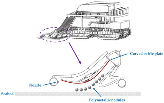
Figure 1.
Schematic diagram of a Coandă effect-based hydraulic-type collector [7].
Design of Coandă effect-based collector needs theoretical guidance in the flow character of curved flow and law of jet flow-nodule interaction. Kim et al. [3] proposed a global optimization method based on curved wall jet that predicts the collection efficiency of the collector. Jia et al. [6] developed the reduced model of wall jet over a curved surface to predict the lift force on the nodules. In their work, the Coandă effects were strengthened with lower wall height, higher jet slot height and higher initial velocity.
It has been shown that growth rate of a high-speed wall jet is significantly affected by the local curvature of the surface [13,14]. For flows blowing around curved surfaces of constant radius, i.e., circular cylinders, continuous variation of the rate of growth is observed along with downstream distance. Consider that the circular cylinder surface is actually one special issue of logarithmic spiral surfaces; the latter has seldom been systematically studied. A jet that emerges tangentially onto a convex wall of logarithmical spirals forms a self-preserving flow with the skin friction is effectively constant. How the self-preserving nature of the logarithmic spiral surfaces affect nodule pick up remains uncertain.
In the present investigation, we studied the lift ability of the reduced form of a Coandă effect-based collector model, with logarithmic spiral surfaces. In Section 2.1, particular care was taken to establish turbulent jets over convex logarithmic spiral walls. The effects of wall curvature on the growth rate and theory prediction of particle lift are illustrated in Section 2.2 and Section 2.3. In Section 3, the modified theory is examined and the spread of the fully developed wall jet is studied for two logarithmic spiral walls influenced by several factors. Section 4 mainly discusses the relationship of decay of the mean flow with the collection of the nodules. The conclusion is summarized in Section 4.
2. Materials and Methods
Figure 2 displays the 2D turbulent wall jet on a logarithmic spiral wall, accompanied with a curvilinear coordinate system. The polar equation of logarithmic spirals is given by
where r is the distance from the origin to the local position, θ is the angle from the x-axis, and a1 and a2 are arbitrary constants. Given that
and a1, the logarithmic spiral surface in Figure 1 can be assured. In the pre-prototype design of Coandă effect-based pick-up devices, the jet slot should be located at a certain θ based on a virtual origin at point O in Figure 2.
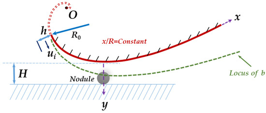
Figure 2.
Schematic diagram of a turbulent jet flow over logarithmic spiral wall surface, with a curvilinear x-y coordinate system. The jet exits from a slot height h at a velocity of ui. The R, b, and H represent the local curvature radius, jet half-width, and wall distance deviated from the ground, respectively. The R0 is the radius of curvature at the starting point of the curve. O is the virtual origin of the curved surface.
2.1. Mass and Momentum Balance
The flow shown in Figure 2 has been assumed to be incompressible. The time-mean continuity equation for two-dimensional turbulent flow over a curved wall with local radius R is
The corresponding momentum equation along the wall is [13]:
while orthogonal to the wall is
In this paper, R is taken as positive function of x, i.e., R(x), which represents logarithmic spiral curves. The following expressions can be deduced from the above conservation laws.
2.2. Effect of Wall Curvature on the Growth Rate
To study how the surface curvature affects the growth rate of turbulent wall jets, the relationship was performed between the growth rate and the rate of curvature change in high Reynolds numbers [10]:
where b is the jet half width, and n, , are constants and were determined as 6 and 0.8814, respectively [11]. Actually, for a wall jet along a plane wall, i.e., b/R = 0, Equation (6) becomes
The coefficient K is known experimentally as 0.073. Equation (6) depends on the variation of R(x) and can be solved in the case of logarithmic spiral under the premise of R/x = constant:
2.3. Prediction of Particle Lift in Jet Flows on Logarithmic Spirals
The y-direction momentum equation can be simplified to solve. Retaining the dominant terms in Equation (5), the pressure is determined from
The turbulent normal stress term is ignored, considering its minor contribution to the uniform momentum transport. Equation (9) thus is simplified as
Based on the self-preservation assumption, the mean velocity profile at a certain normal section of the wall is obtained by normalizing the velocities and lengths by the local maximum velocity um(x) and the related jet half-width b(x):
where ξ = y/b(x), in which b can be solved by Equation (8), and ξm = ym/b(x) stands for the non-dimensional position of the maximum velocity.
Functional relations for behavior of b and x-direction maximum velocity um are proposed as
where h and ui are the jet slot height and the jet exit velocity, respectively. Similarly, b is solved by Equation (8). The pressure and velocity field can be solved from Equations (10)–(13), in which the pressure field can be acquired as [6]:
where C is p(y) value computed by Equation (14) at .
According to Jia et al. [6], the lift index has been proposed to evaluate the gather performance, which is written
where Flft and Gnd are the lift force and the nodule weight, respectively. The nodule is considered to have been collected as LIF = 1.
3. Results
3.1. Validation
In Figure 3, the theoretical mean velocity profiles of x/R = 2/3 and x/R = 1 are plotted as compared with the experimental profile. The results are seen to collapse onto a single curve with non-dimensionalization. The value of ym/b increases slightly as the x/R is increased. In view of the agreement between experiment data and theory, our model appears to be justified.
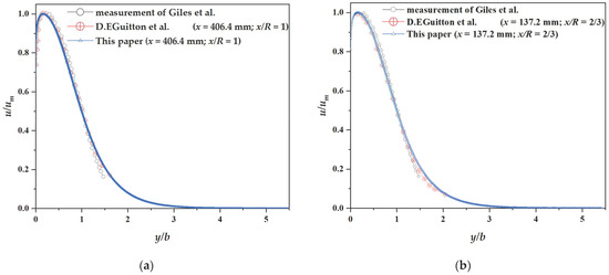
Figure 3.
Mean velocity profiles. (a) x/R = 1; (b) x/R = 2/3 [13,14].
3.2. Growth Rate
The jet half width y1/2m is shown as a function of distance around the surface in Figure 4. The jet half-width increased in proportion to x. The growth rate increased with x/R, in which the most highly curved jet (x/R = 4/3) rose approximately eleven times faster than that for x/R = 1/3.
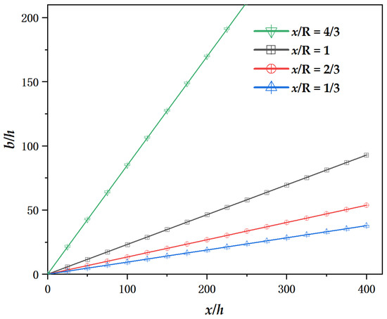
Figure 4.
Jet growth with downstream distance.
3.3. Parameters Affect the Jet Flow and Lift Index on Logarithmic Spirals
An analysis was performed to predict the effects of the three key parameters, i.e., jet exit velocity ui, non-dimensional jet downstream distance x/h, and the non-dimensional slot height h/R0, on the mean flow and lift capability in the wall jets of logarithmic spirals with x/R = 1 and x/R = 2/3. The H is 40 mm.
3.3.1. Jet Exit Velocity ui
Figure 5 shows velocity distributions of wall flow on logarithmic spiral with different ui at x = 86 mm and h = 2 mm, where x is the distance from virtual origin of spiral. The position of maximum velocity tends to deviate from the surface with x/R increasing from 2/3 to 1. For the spiral of x/R = 1, the um occurred at y = 3.2 mm and increased by 0.63 m/s when ui increased by 2 m/s. By contrast, for the spiral of x/R = 2/3, the ym reduced to 1.8 mm and the um rose by 0.89 m/s. The pressure along y direction is shown in Figure 6, which rose markedly at distance smaller than y = 20 mm, and then slowed down to reach a constant value. The LIF was performed on particle diameters ranging from 0–30 mm, with results shown in Figure 7. The LIF first decreased dramatically (dp < 10 mm), and then tended to almost stand still. In the case of x/R = 1, all the tested particles could be successfully collected at ui ≥ 12 m/s, which is less than that of jet flowing over circular cylinder (ui ≥ 14 m/s) [6]. Conversely, in the case of x/R = 2/3, only particles smaller than 15 mm could be lifted with ui = 14 m/s.
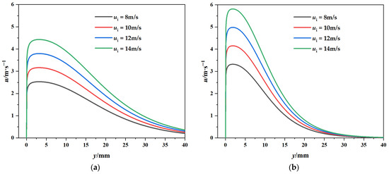
Figure 5.
Velocity distribution with different ui over logarithmic spiral wall surfaces at (a) x/R = 1 and (b) x/R = 2/3.
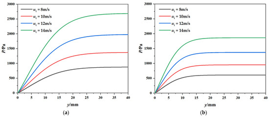
Figure 6.
Pressure distribution with different ui over logarithmic spiral wall surfaces at (a) x/R = 1 and (b) x/R = 2/3.
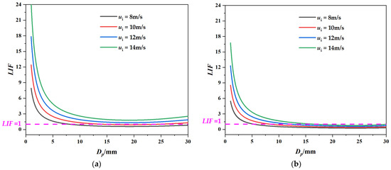
Figure 7.
Lift index with different ui over logarithmic spiral wall surfaces at (a) x/R = 1 and (b) x/R = 2/3.
3.3.2. Jet Downstream Distance x/h
The jet velocity with ui = 10 m/s and h = 2 mm but differing local x values is displayed in Figure 8. The velocity showed a continuous variation in the shape of its profile with local wall curvature. In a logarithmical spiral of x/R = 1, um declined from 5.9 m/s to 1.9 m/s with the increase of x/h from 14.3 mm to 100.7 mm, while in a spiral of x/R = 2/3, um dropped from 7.3 m/s to 2.5 m/s. Figure 9 displays the increase of pressure with increasing x. The pressure curve first increased nearly in proportion to x/h then tended to be flat. Figure 10 employs the particle as abscissa, and displays a remarkably downward trend. It can be noted that at an early position of x/h = 14.3 in both the logarithmical spirals, nodules with diameters larger than 15 mm cannot be lifted.
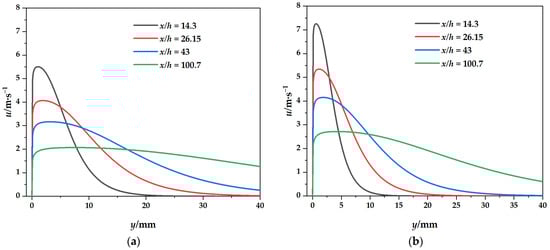
Figure 8.
Velocity distribution with different x/h over logarithmic spiral wall surfaces at (a) x/R = 1 and (b) x/R = 2/3.
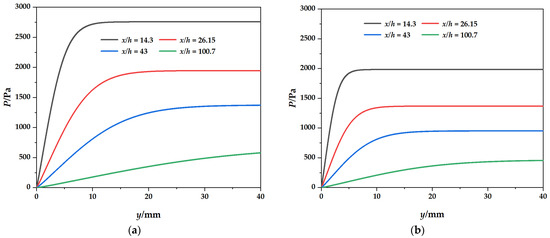
Figure 9.
Pressure distribution with different x/h over logarithmic spiral wall surfaces at (a) x/R = 1 and (b) x/R = 2/3.
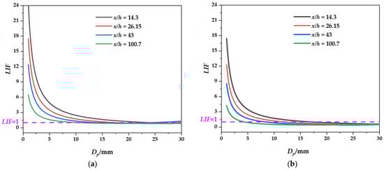
Figure 10.
Lift index with different x/h over logarithmic spiral wall surfaces at (a) x/R = 1 and (b) x/R = 2/3.
3.3.3. Non-Dimensional Slot Height h/R0
Figure 11, Figure 12 and Figure 13 show the velocity, pressure, and lift index profile of the ui = 10 m/s and x = 86 mm, but with differing h/R0. In the logarithmical spiral of x/R = 1, um rose from 2.2 m/s to 4.5 m/s with the increase of h/R0 from 0.0073 to 0.0291, while in the spiral of x/R = 2/3, um dropped from 7.6 m/s to 3.8 m/s, with faster decay at the y-direction. The positive-growth profile of pressure distribution first increased markedly at distance smaller than y = 20 mm (x/R = 1) or y = 10 mm (x/R = 2/3), and then slowed down to reach a constant value. The observed lift index decreased with increasing particle diameter, first sharply and then slightly (Figure 13). It is apparent that the lift capability of jet flow in a logarithmical spiral of x/R = 1 is better than that of x/R = 2/3.
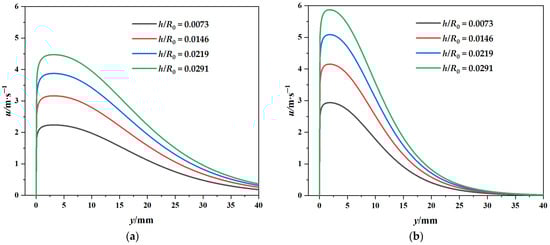
Figure 11.
Velocity distribution with different h/R0 over logarithmic spiral wall surfaces at (a) x/R = 1 and (b) x/R = 2/3.
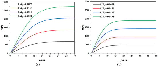
Figure 12.
Pressure distribution with different h/R0 over logarithmic spiral wall surfaces at (a) x/R = 1 and (b) x/R = 2/3.
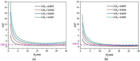
Figure 13.
Lift index with different h/R0 over logarithmic spiral wall surfaces at (a) x/R = 1 and (b) x/R = 2/3.
4. Discussion and Conclusions
The objective of this research is to investigate the theoretical lift properties of a curved wall jet with continuous changed curvature. The motion equation was performed in the jet region of a turbulent wall jet by integration, on the assumption that velocity profiles of wall region are approximately similar to one another, to a certain extent. The jet half-width b was expressed as a function of x and R, which is more reasonable than the approximation of b = H − dp [3,6]. The jet entrains the surrounding still fluid, therefore the maximum velocity drops and the flow width increases downward (as shown in Figure 8). The growth rate, which represents the width of the main jet flow, rises in proportion to x. The growth rate of the Coandă jet is significantly influenced by surface curvature, revealing a sharp increase when x/R is more than 1.
The Coandă effect over logarithmical spirals was found to be stronger with higher jet exit velocity, larger local curvature, and non-dimensional jet slot height. The threshold ui in lift index decreased with an increase in x/R to pick up the nodules with dp less than 30 mm. With ui of 10 m/s lift, the particle at an early position of the logarithmical spiral (i.e., with small x) has little influence to the lift index. Additionally, the lift index, corresponding to a variation in the x/R, was closely related to the growth rate. The lift capability of jet flow in logarithmical spiral of x/R = 1 is better than that of x/R = 2/3, especially in the case study of ui and h/R.
In the logarithmical spiral surfaces, the surface pressure was lower than ambient and rose only slowly, thus the jet can remain attached in most cases. It is supposed that there is an upper limit value of x/R, at which the flow of wall jet separates from the surface before full development. The separation seems to be attributed to a steep positive pressure gradient, which increases with x/R. In that case, the growth of width is not always proportional to x [13]. It was observed in the experiment that a rapid increase of width for x/R = 1.25 resulted in separation of jet from the wall surface [13]. This will be described in detail in a following report.
Specifically, the correlation visible on Figure 7, Figure 10 and Figure 13 applies if the particle diameters are not adjacent to the curve height. The relatively large particles are greatly affected by the ratio of particle size to common eddy size, as small eddies may not be able to support large particles.
Author Contributions
Conceptualization, H.J. and X.S.; methodology, H.J.; software, J.Y.; validation, J.Y.; formal analysis, H.J.; investigation, H.J.; resources, H.J.; data curation, Y.W.; writing—original draft preparation, H.J.; writing—review and editing, X.S. and K.W.; visualization, Y.W.; supervision, K.W.; project administration, J.Y.; funding acquisition, H.J. All authors have read and agreed to the published version of the manuscript.
Funding
This research was funded by the National Nature Science Foundation of China (52206056), National Key Research and Development Program (2021YFC2800803 and 2021YFC2801503), Science Foundation of Zhejiang Sci-Tech University (ZSTU) (19022101-Y).
Institutional Review Board Statement
Not applicable.
Informed Consent Statement
Not applicable.
Data Availability Statement
The data presented in this study are available on request from the corresponding author.
Conflicts of Interest
The authors declare no conflict of interest.
References
- Handschuh, R.; Grebe, H.; Panthel, J.; Schulte, E.; Ravindran, M. Innovative deep ocean mining concept based on flexible riser and self-propelled mining machines. In Proceedings of the Fourth Isope Ocean Mining Symposium, Szczecin, Poland, 23–27 September 2001. [Google Scholar]
- Jia, H.; Wang, Y.; Zhu, Z.; Su, X.; Tang, Z. Coarse particle motion characteristics in a double-stage slurry pump considering leakage flow. Shock Vib. 2021, 2021, 5904446. [Google Scholar] [CrossRef]
- Kim, S.; Cho, S.G.; Kim, J.; Lee, T.H.; Chi, S.B. Reliability-based design optimization of a pick-up device of a manganese nodule miner using correlated and grouped manganese nodule data. In Proceedings of the 13th World Congress of Structural and Multidisciplinary Optimization (WCSMO-13), Beijing, China, 20–24 May 2019. [Google Scholar]
- Oebius, H.U.; Becker, H.J.; Rolinski, S.; Jankowski, J.A. Parametrization and evaluation of marine environmental impacts produced by deep-sea manganese nodule mining. Deep Sea Res. Part II Top. Stud. Oceanogr. 2001, 48, 3453–3467. [Google Scholar] [CrossRef]
- Cho, S.G.; Park, S.; Oh, J.; Min, C.; Kim, H.; Hong, S.; Jang, J.; Lee, T.H. Design optimization of deep-seabed pilot miner system with coupled relations between constraints. J. Terramech. 2019, 83, 25–34. [Google Scholar] [CrossRef]
- Jia, H.; Yang, J.; Su, X.; Xia, Q.; Wu, K. Theoretical prediction on hydraulic lift of a coandă effect-based mining collector for manganese nodule. Energies 2022, 15, 6345. [Google Scholar] [CrossRef]
- Yue, Z.; Zhao, G.; Xiao, L.; Liu, M. Comparative study on collection performance of three nodule collection methods in seawater and sediment-seawater mixture. Appl. Ocean Res. 2021, 110, 102606. [Google Scholar] [CrossRef]
- Hu, J.; Zhao, G.; Xiao, L.; Liu, M. Experimental investigation on characteristics of flow field in ‘suck-up-based’ and ‘coandă-effect-based’ nodule pick-up devices. In Proceedings of the The 30th International Ocean and Polar Engineering Conference, Virtual, 11–16 October 2020. [Google Scholar]
- Kim, M.; Kim, H.D.; Yeom, E.; Kyung, K.C. Flow characteristics of three-dimensional curved wall jets on a cylinder. J. Fluids Eng. Trans. ASME 2018, 140, 041201. [Google Scholar] [CrossRef]
- Roberts, L. A theory for turbulent curved wall jets. In Proceedings of the 25th AIAA Aerospace Sciences Meeting, Reno, NV, USA, 24–26 March 1987. [Google Scholar]
- Rodman, L.C.; Wood, N.J.; Roberts, L. Experimental investigation of straight and curved annular wall jets. AIAA J. 1989, 27, 1059–1067. [Google Scholar] [CrossRef]
- Lee, M.U.; Hong, S.; Choi, J.S.; Kim, H.W.; Yeu, T.K.; Min, C.H.; Cho, S.G.; Lee, T.H. Design optimization of a hydraulic deep-sea manganese pick-up device using coanda effect. In Proceedings of the KSME 2013 Spring Annual Meeting, Busan, Republic of Korea, 23–24 May 2013; pp. 1660–1665. [Google Scholar]
- Guitton, D.E.; Newman, B.G. Self-preserving turbulent wall jets over convex surfaces. J. Fluid Mech. 1977, 81, 155–185. [Google Scholar] [CrossRef]
- Giles, J.A.; Hays, A.P.; Sawyer, R.A. Turbulent wall jets on logarithmic spiral surfaces. Aeronaut. Q. 1966, 17, 201–215. [Google Scholar] [CrossRef]


Disclaimer/Publisher’s Note: The statements, opinions and data contained in all publications are solely those of the individual author(s) and contributor(s) and not of MDPI and/or the editor(s). MDPI and/or the editor(s) disclaim responsibility for any injury to people or property resulting from any ideas, methods, instructions or products referred to in the content. |
© 2023 by the authors. Licensee MDPI, Basel, Switzerland. This article is an open access article distributed under the terms and conditions of the Creative Commons Attribution (CC BY) license (https://creativecommons.org/licenses/by/4.0/).