Article

Preparation and Super-Hydrophobic Mechanism Analysis of FAS-17-Modified SiO2/PDMS Coatings for High-Voltage Composite Insulators

1
School of Chemistry and Chemical Engineering, Southeast University, Nanjing 210096, China
2
Jiangsu Frontier Electric Technology Co., Ltd., Nanjing 210000, China
3
Shanghai Electro-Mechanical Engineering Institute, Shanghai 201109, China
*
Author to whom correspondence should be addressed.
Coatings 2023, 13(3), 563; https://doi.org/10.3390/coatings13030563
Submission received: 31 January 2023 / Revised: 28 February 2023 / Accepted: 1 March 2023 / Published: 6 March 2023
(This article belongs to the Section Surface Characterization, Deposition and Modification)

Abstract

:
Pollution flashover on insulators is one of the greatest challenges affecting the smooth operation of high-voltage transmission lines. Demonstrating super-hydrophobic coatings on insulators’ interfaces is an effective measure to prevent insulator flashovers. In the present investigation, a super-hydrophobic FAS-17-modified SiO2/PDMS coating on a composite insulator was demonstrated by spraying. The coating had a contact angle of 159.2° and a sliding angle of 1.3° with better insulation properties. The prepared FAS-17-modified nano-SiO2 nanoparticles were not easy to agglomerate; to illustrate this, the binding energy was calculated by the density functional theory. The super-hydrophobic mechanism of the coating was explained in terms of the adsorption energy between SiO2 molecules and water before and after modification. This paper provides a new method to solve the pollution flashover problem of insulators and a new angle to explain the super-hydrophobic mechanism.

1. Introduction

Electricity has become a necessity, and failing to keep the high-voltage transmission line running smoothly causes huge economic losses [1,2,3]. Previous reports have shown that the vast majority of electrical accidents were caused by insulator pollution flashovers [4,5,6]. Thus, finding ways to keep insulators clean is important to making high-voltage transmission lines run smoothly.
The main component of pollution on insulators is an inorganic salt (mainly NaCl and CaSO4) [7,8,9,10], the accumulation of which increases the conductivity. Under the action of water and the electric field [11], the surface of insulators is discharged [1], and in serious cases, a large area of the power grid is cut off, bringing great economic losses to the power system. At present, the methods of cleaning insulators are as follows: laser cleaning [12], dry-ice cleaning [13], artificial spray cleaning [14], etc. The applications of laser cleaning and dry-ice cleaning are limited because the equipment is not suitable for the field environment. Currently, the main cleaning method is still for electric workers to flush the insulator with a high-pressure water gun [15], which has great potential for safety hazards. Therefore, it is better to build a protective coating on the surface of the insulator than to remove the pollution after it accumulates.
Super-hydrophobic coatings are often used as antifouling protective coatings because of their unique self-cleaning properties [16,17,18]. Coatings with contact angles greater than 150° and sliding angles less than 10° are called super-hydrophobic coatings [19,20]. Super-hydrophobic coatings consist of two parts. One is the low-surface-tension polymer substrate, and the other is the nanoparticles with higher roughness [21,22]. Polymer materials used as low-surface-tension substrates can be classified as fluorinated long-chain hydrocarbons and fluorine-free long-chain hydrocarbons. Hydrocarbons with fluorinated long chains, such as polyvinylidene difluoride (PVDF), poly tetra fluoroethylene (PTFE), and poly(3-trifluoroethoxymethyl-3-ethyloxetane) (P3F), can greatly reduce the surface energy to meet the requirements of super-hydrophobic material substrate layer [23,24,25,26]. The prominent shortcomings of fluorine-rich coatings are their high prices and non-biodegradable nature [27]. Therefore, fluorinated long-chain hydrocarbons are not suitable for use as substrates on a large scale. Because of the significant shortcomings of fluorocarbons, fluorine-free polymers are more suitable as the base material for making super-hydrophobic coatings. In recent reports, polydimethylsiloxane (PDMS) elastomers have emerged as excellent representatives of fluorine-free polymers [28]. This kind of elastomer has a certain transparency, strong flexibility, good mechanical elasticity, lower cost than fluoro-containing polymers, and good adhesion on various substrate surfaces [29,30]. The surface tension (20 mN/m) of PDMS is relatively low [29], and the chemical properties of PDMS are stable [31]. Owing to these advantages, PDMS is suitable to be selected as the substrate. As for the choice of nanoparticle, nano-SiO2 [32], nano-Fe2O3 [33], and nano-Al2O3 [34] are common choices. Considering the insulators are used in a high-voltage transmission line, the breakdown voltage is an important parameter to measure. According to a previous report, SiO2 has a proper breakdown voltage [35]. However, small nano-SiO2 particles tend to aggregate into larger particles, which affects the stability and flatness of the coating surface [36]. In order to ease the agglomeration of nanoparticles (NPs), the introduction of long-chain molecules on the surface of SiO2 is a common method [37,38]. Xue Dai et al. constructed a super-hydrophobic porous SiO2@PDMS protective layer using the spraying method with a contact angle of 155° [39], indicating that the contact angle can increase to reach better self-cleaning performance. O. Rius-Ayra et al. fabricated a super-hydrophobic PDMS@304 stainless-steel mesh using a chemical etching method [40]. The contact angle of the PDMS@304 stainless-steel mesh reached 159°, but the method used a large number of toxic and harmful chemicals, which is not environmentally friendly.
Therefore, based on the previous research, we designed a super-hydrophobic coating that is environmentally friendly and has a larger contact angle. In our work, 1H, 1H, 2H, 2H-perfluorodecyltriethoxysilane (FAS-17) was selected to modify SiO2. FAS-17 has a long carbon chain and 17 fluorine atoms in its molecule. It can react with SiO2 to form Si-O-Si bonds under alkaline conditions [37]. The agglomeration of NPs is alleviated from two points. The long carbon chain increases the steric hindrance [41]. Seventeen fluorine atoms greatly reduce the surface energy [27].
In this article, first, FAS-17-modified nano-SiO2 was prepared. Then, PDMS was used as the low-surface-energy substrate, and FAS-17 was used to fabricate the FAS-17-modified SiO2/PDMS super-hydrophobic interface. Meanwhile, the agglomeration mechanism of nano-SiO2 and the super-hydrophobic mechanism of FAS-17-modified SiO2/PDMS coatings were analyzed. In order to evaluate the insulating properties, the breakdown voltage of the super-hydrophobic coatings was tested.

2. Experiment

2.1. Materials

TetraEthyl Orthosilicate (TEOS, analytically pure) and Dibutyltin Dilaurate (analytically pure) were both obtained from Shanghai Macklin Biochemical Co., Ltd. (Shanghai, China).
The 107 RTV-silicone rubber (PDMS, analytically pure) was purchased from Shanghai Aladdin Biochemical Technology Co., Ltd. (Shanghai, China).
1H, 1H, 2H, 2H-perfluorodecyltriethoxysilane (FAS-17, analytically pure) was purchased from Shanghai Bide Medical Technology Co., LTD. (Shanghai, China).
Anhydrous ethanol (analytically pure) and ammonia solution (analytically pure, 26 wt %) were purchased from Shanghai Aladdin Biochemical Technology Co., Ltd. (Shanghai, China)
All chemicals were used as received without any further purification.

2.2. Instrument and Apparatus

Vacuum drying oven and air pump (Shanghai Jing Hong Experimental Equipment Co., LTD., Shanghai, China); spray pen (Taiwan U-Star spraying tools Co., Ltd., Taiwan, China); OCA20 contact angle tester (DataPhysics Instruments GmbH, Filderstadt, Germany); Nicolet 5700 FT-IR (Thermo Fisher Scientific Inc., Waltham, MA, USA); Nova Nano SEM450 (Thermo Fisher Scientific Inc., Waltham, MA, USA); Ultim Extreme EDS (Oxford Instrument, London, UK); BTS-75 breakdown voltage tester (Beijing Xing Di Instrument Co., LTD., Beijing, China).

2.3. Method

2.3.1. The Preparation of Nano-SiO2

Nano-SiO2 was prepared using the Stöber method [42].
In detail, first, 2.0 g of TEOS, 40.0 g of CH3CH2OH, 4.0 g of H2O, and 0.30 g of NH3·H2O (the catalyst) were added into a three-hole flask and heated at 45 °C with magnetic stirring at 1000 rpm or 4.5 h. Thus, the nano-SiO2 was obtained.

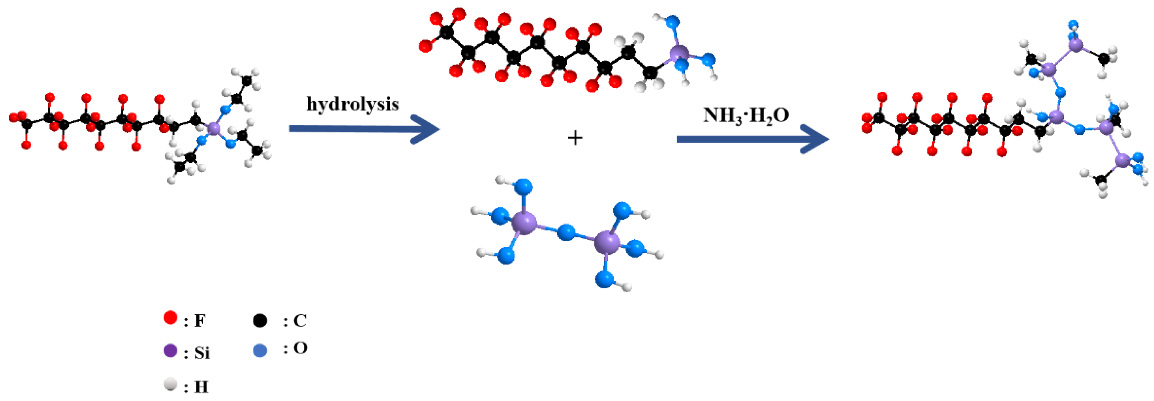
2.3.2. The Preparation of FAS-17-Modified Nano-SiO2

A total of 5 g of nano-SiO2 was dissolved in 100 mL of a 95% ethanol–water solution in a beaker. Then, the beaker was placed in an ultra-sonic atmosphere to obtain a transparent white emulsion. After 20 min, the mixture was transferred into a 250 mL three-hole flask. Then, 0.25 g of FAS-17 and 0.1 g of NH3·H2O were added into the flask. Then, the dispersion was heated at 70 °C under magnetic stirring for 5 h. Then, the mixture was heated in a vacuum oven for 6 h. Finally, the mixture was ground into a white powder.
Figure 1 briefly shows the principle of synthesizing FAS-17-modified nano-SiO2.

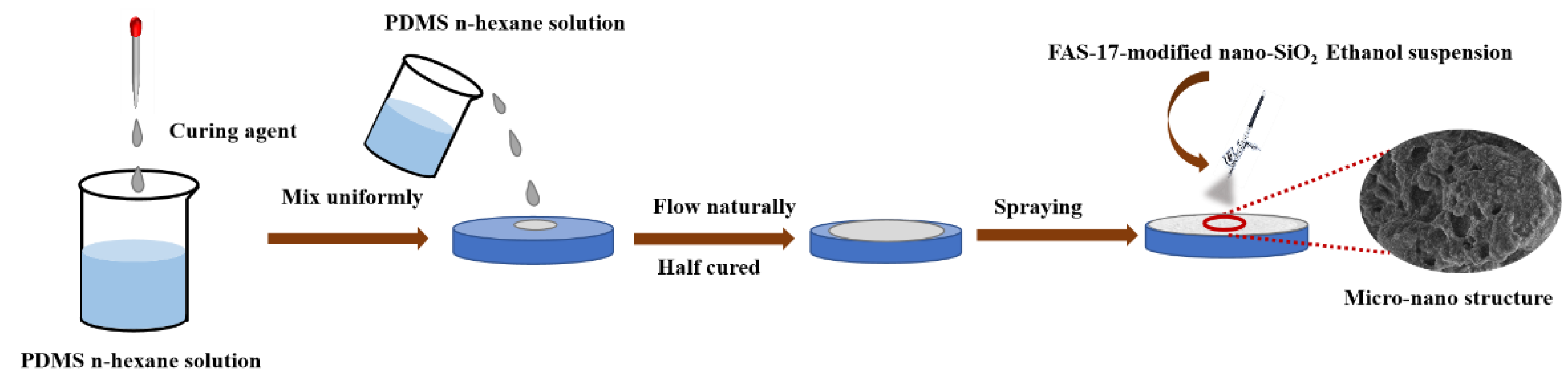
2.3.3. The Preparation of Super-Hydrophobic Coating

A total of 10 g of PDMS was added into the beaker and dissolved in n-hexane. After magnetic stirring for 15 min, 1 g of dibutyltin dilaurate was added to the solution. A pre-cleaned insulator silicone rubber was laid flat on a glass plate. Then, the solution was poured onto the silicone and heated in the vacuum oven for 0.5 h at 80 °C to let it half dry. FAS-17-modified nano-SiO2 was dissolved in ethyl alcohol. Then, the solution was sprayed onto the surface of PDMS with a spray pen. Finally, the silicone rubber was heated in the vacuum oven at 100 °C for 2 h, and the super-hydrophobic RTV-silicone rubber was obtained.
Figure 2 briefly shows the construction process of FAS-17-modified nano-SiO2/PDMS coatings.

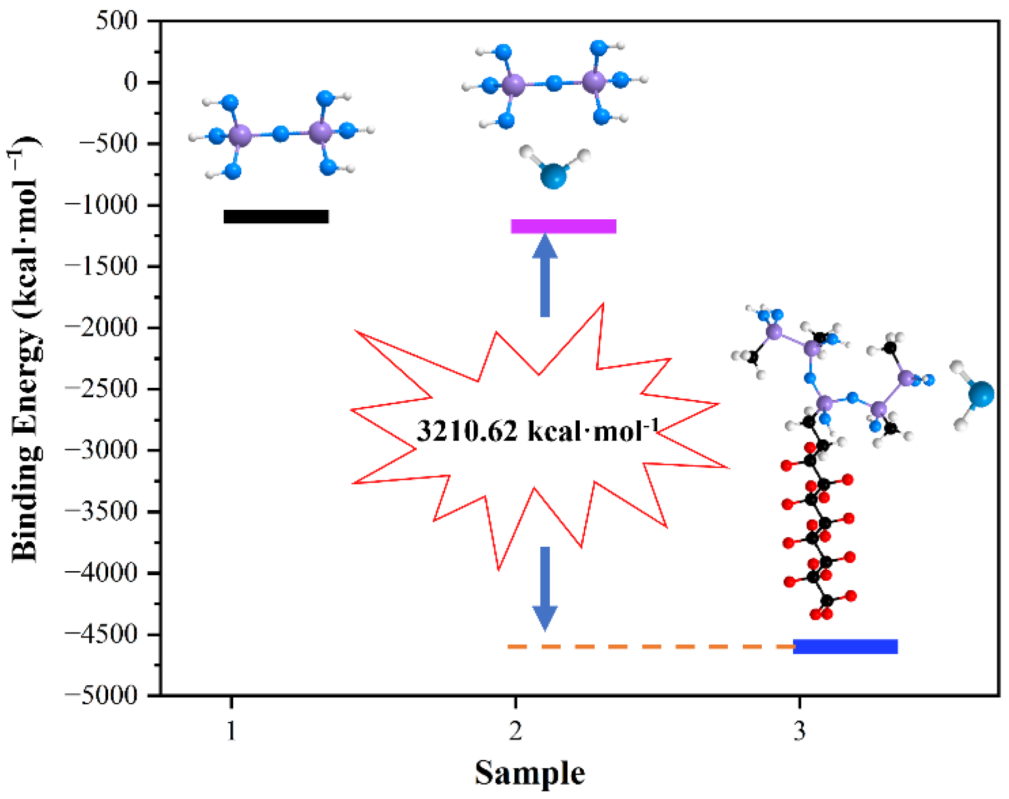
2.3.4. The Preparation to Calculate the Binding Energy

Binding energy (BE) is the energy released when several particles combine from a free state into a composite particle that can be used to evaluate the firm degree of molecular binding.
In quantum chemistry, it can be calculated by substituting the equation E BE =   E comp E mon into the binding energies of the compound (comp) and monomer (mono), where EBE is the binding energy of two molecules, Ecomp is the adsorption energy of the compound, and Emono is the adsorption energy of the monomer that builds the compound.
The binding energy between two molecules and the energy of the monomer were calculated through the Gaussian16 software package using the density functional theory (DFT). The M06-2X density function and the def2-TZVP basis set were used to optimize the structure and calculate the energy.

2.4. Characterization

A contact angle–measuring instrument equipped with a tilting table was used to measure the contact angle and sliding angle. Three random parts on the surface of the sample were used for testing. The volume of the droplets to test the contact angle was 2 μL. The volume of the droplets to test the sliding angle was 10 μL.
Nova Nano SEM450 SEM (Thermo Fisher Scientific Inc., Tokyo, Japan) was used to investigate the morphology of the samples. The extraction voltage was 5.00 KV. All the samples were previously metalized for 2 min using a high-resolution sputtering coating instrument Q150T S (Quorum Technologies, Chico, CA, USA).
Ultim Extreme EDS (Oxford Instrument, London, UK) was used to characterize the elemental composition and content of the samples.
Nicolet 5700 FT-IR (Thermo Fisher Scientific Inc., Waltham, MA, USA) was used to illustrate the successful introduction of fluorine on SiO2.

2.5. Performance Testing

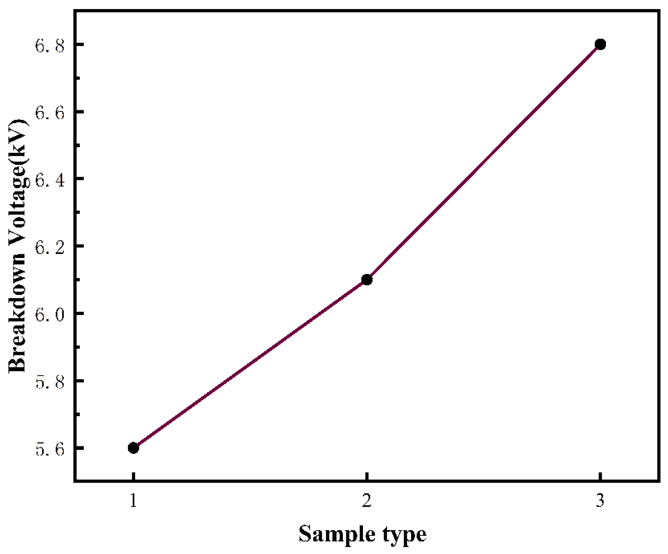
Power Grid Security Test

In order to evaluate the anti-pollution flashover performance, the breakdown voltage of the FAS-17-modified nano-SiO2–coated silicone rubber composite insulator was tested using a BTS-75 breakdown voltage tester (Beijing Xing Di Instrument Co., Ltd., Beijing, China). The rapid uniform voltage boost method was used to raise the voltage, and the voltage boost speed was 1 kV/s.

3. Results and Discussion

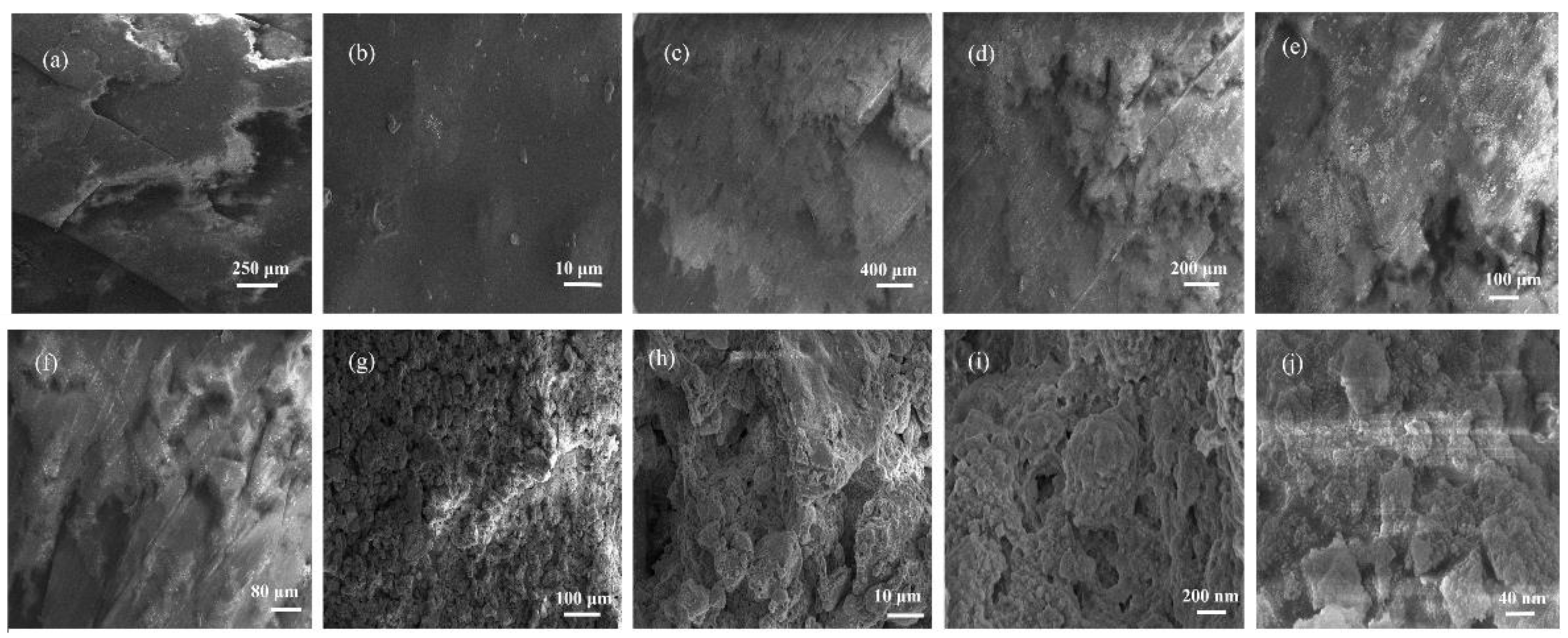
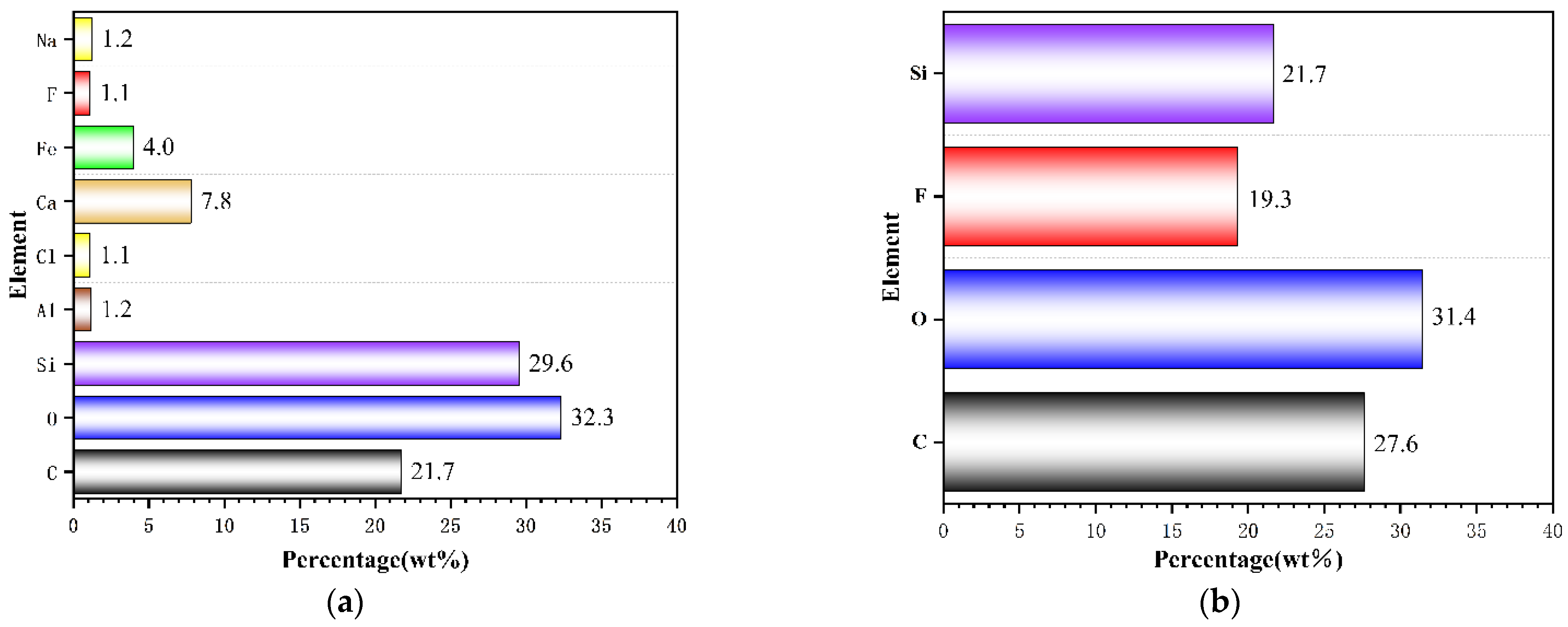
3.1. Analysis of Surface Morphology and Elemental Distribution

By observing Figure 3a,b, the surface of the composite insulator has many cracks and is relatively smooth without a rough transparent structure. Figure 3c–f are the SEM images of the PDMS surface. There are fewer cracks in the PDMS surface. It can be seen from the SEM image that the micro-nanoscale, mastoid-like structure on the primer substrate was formed by the atomization effect in the spraying process, in which the introduction of FAS-17-modified nano-SiO2 played a critical role. Many holes were found in the micro-nanostructure. The scale of the holes is around 20–60 nm. The primer PDMS substrate obtained in the absence of FAS-17-modified nano-SiO2 is relatively flat without any mastoid-like structure.
Figure 4a shows the EDS diagram and elemental distribution of the composite insulator. It can be seen that the main element on the surface are C, O, Ca, and Fe. The elements Na, F, Cl, and Al are the minorities.

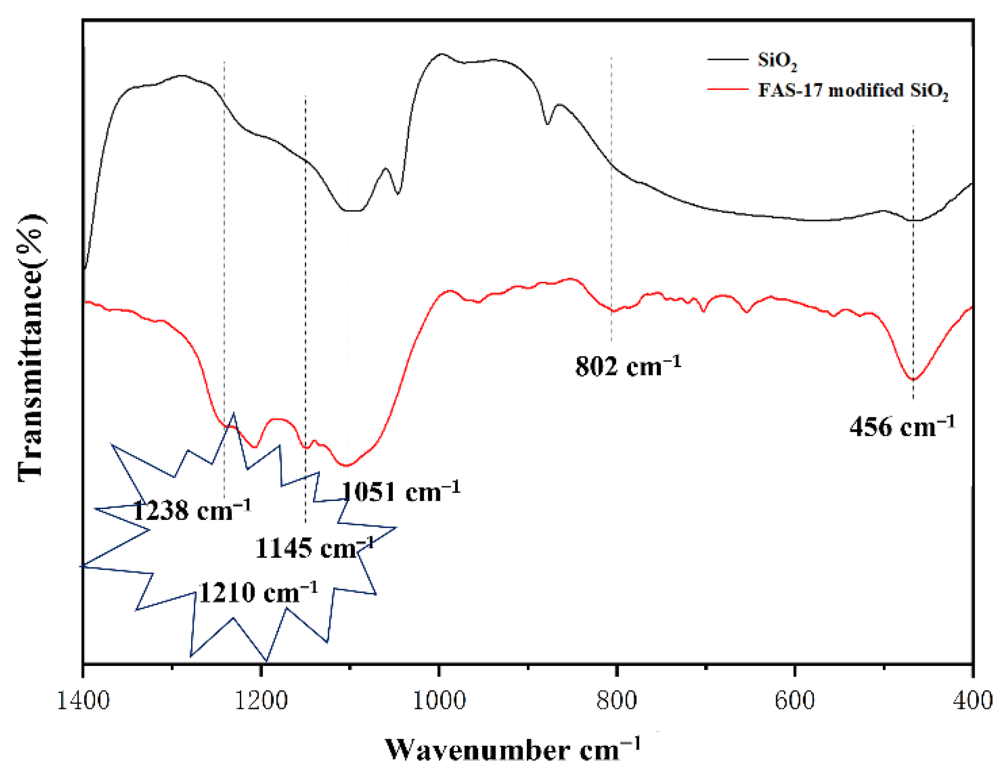
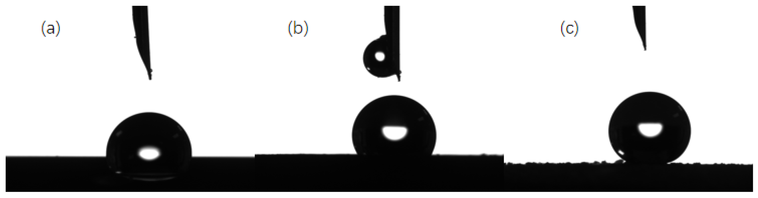
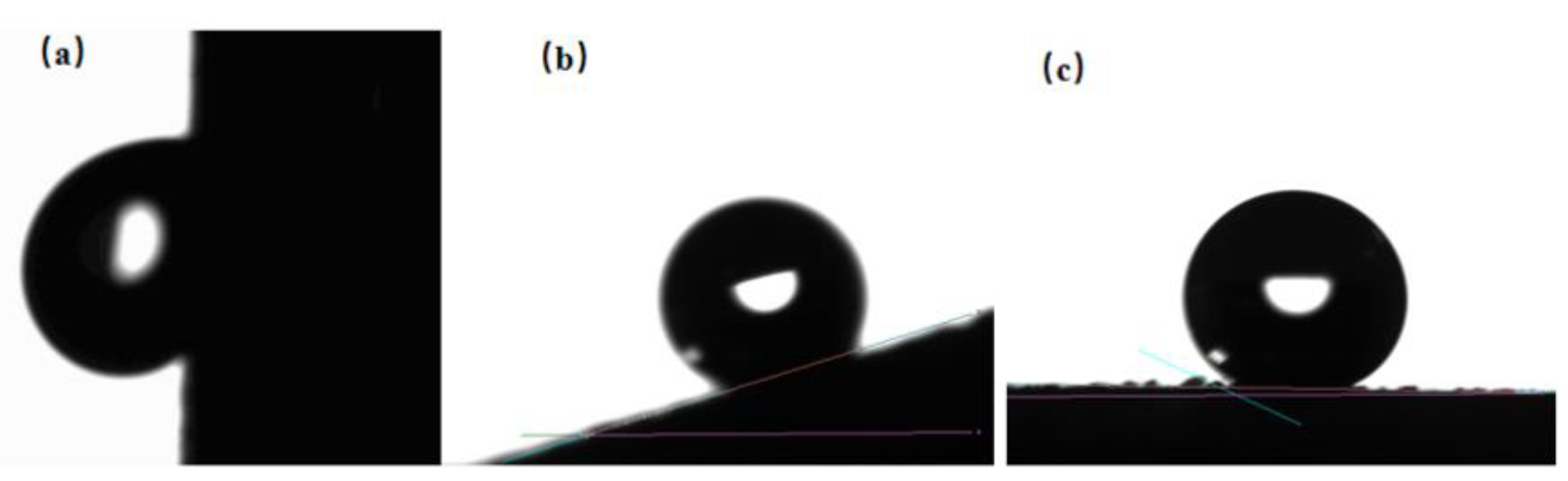
3.2. Analysis of Super-Hydrophobic Coating

The super-hydrophobic coatings constructed on the surface of the composite insulator were achieved by sequentially naturally flowing flat PDMS (used as a low-surface-energy material) and spray-depositing FAS-17-modified nano-SiO2 (used to increase surface roughness) on it. The successful introduction of fluorocarbon groups can be confirmed by the FT-IR spectra. Compared with the FT-IR spectra of SiO2, FAS-17-modified SiO2 shows adsorption bands at 1238, 1210, and 1145 cm−1, which are attributed to the C-F stretching vibration of the -CF3 and -CF2- groups in the fluorinated alkyl chains (Figure 5). By comparing Figure 4b with Figure 4a, it can be found that the rate of the F element increased sharply, which indicates that the FAS-17-modified nano-SiO2/PDMS were successfully constructed.

3.3. SiO2 Agglomeration Mechanism and FAS-17-Modified Nano-SiO2 De-Agglomeration Mechanism

The agglomeration of NPs can be divided into two states: hard aggregate and soft aggregate. The formation of hard agglomerations is mainly influenced by electrostatic forces, van der Waals forces, and chemical bonds. Soft agglomerations are mainly caused by electrostatic forces and van der Waals forces between particles or capillary forces due to the presence of liquid in the agglomerations.
Theoretically, the whole motion process of NPs agglomeration can be divided into three stages:
(a)
Particles approach the phase of motion;
(b)
Contact phase;
(c)
Agglomerative growth stage.
The classic DLVO theory describes the change in the total interaction energy experienced by one nanoparticle as it approaches another. The theory is shown as the following formula (VA is a short-range attractive van der Waals potential, and VR is a long-range repulsive electrostatic potential) [43,44,45], Table 1 shows the meaning of the symbols of the DLVO theory.
  V total   = V A + V R
where
V R = AR 12 D + 2 π ε ε 0 Ψ 2 e kD
where
κ K = i z i 2 q i 2 c i 2 k B T 2
From the above formula, we can see that the calculation process of the DLVO theory is extremely complex and not intuitive.
Therefore, to directly and quantitatively express the reason why the modified molecules are not easy to agglomerate, the binding energy of SiO2, two SiO2 molecules, and two FAS-17-modified SiO2 molecules were calculated.
As shown in Figure 6, the binding energy of two SiO2 molecules was −2219.10 kcal·mol−1, and the binding energy of two FAS-17-modified SiO2 molecules was −9040.26 kcal·mol−1. After modification, the binding energy of the molecules decreased sharply, which indicates that the two FAS-17-modified SiO2 molecules were not attracted to each other. This is because FAS-17 has a unique molecular structure. As a molecule rich in fluorine, it has a rather low surface energy. The long fluorine–carbon chain in the molecule acts as a barrier, which greatly increases the steric hindrance. The large steric hindrance prevents the agglomeration of modified molecules.

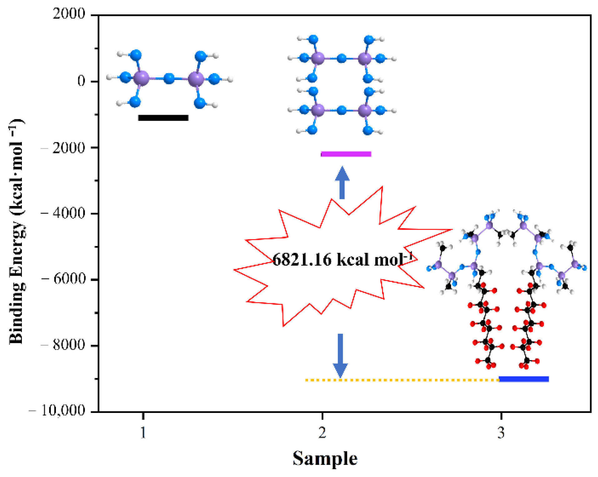
3.4. Super-Hydrophobic Mechanism

As for the super-hydrophobic mechanism of the super-hydrophobic coating, previous reports were mostly interpreted from the low-surface-energy substrate of the coating and the introduction of nanoparticles to increase the roughness.
In our work, PDMS was the low-surface-energy substrate. After merely introducing it on the composite insulator surface, the hydrophobicity of the composite insulator was improved to a certain extent. As shown in Figure 7a,b, the shape of the water droplet on the surface changed from a hemisphere to three-quarters of a sphere, which means that the droplet’s ability to roll on the surface was further improved. Further contact angle and rolling angle tests showed that (see Figure 8), after modification, the angle of droplet rolling was greatly reduced (see Figure 9), the contact angle increased from 104.1° to 115.9°, and the sliding angle decreased from 151.6° to 19.2°.
After spraying FAS-17-modified nano-SiO2 particles on the surface of PDMS, water droplets gained greater possibilities for movement. The shape of the water droplet on the FAS-17-modified nano-SiO2/PDMS surface was very nearly spherical (see Figure 7c). The contact angle increased from 115.9° to 159.2°, and the sliding angle decreased from 19.2° to 1.3°, which indicates that the coatings gained super-hydrophobic properties and a slight disturbance to the surface of the coating could cause the water droplets to move. It can be seen from Table 2 that the contact angle of the prepared FAS-17-modified SiO2/PDMS coatings is in the middle of those of other standard hydrophobic surfaces from the literature.
In order to further explain the variation of hydrophobicity of the coating surface, the binding energy of the coating with water, before and after modification, was calculated. (Figure 10). It is obvious that, after modification, the binding energy decreased sharply from −1185.92 kcal·mol−1 to −4596.55 kcal·mol−1. The low surface binding energy made the adsorption capacity of the modified coating for water very weak, which allowed the water droplet to move freely.

3.5. High-Voltage Safety Evaluation

In order to evaluate the electrical insulation performance of FAS-17-modified SiO2/PDMS samples, the breakdown voltage (the voltage at which the sample breaks down in a continuous boost test) of the samples was tested.
After the breakdown, the current in the loop increases, and the voltage at both ends of the sample drops. The transformer console jumps because of the circuit breaker action and records the maximum test voltage displayed by the capacitor voltage divider. Two kinds of different silicone rubber samples were tested successively, and there were three samples for each. The average value of the three test results was taken to obtain the breakdown voltage of the silicone rubber sample at a room temperature of 20 °C.
It can be seen from Figure 11 that the breakdown voltage of the two types of silicone rubber insulators that the breakdown voltage of the insulator after super-hydrophobic modification was slightly increased from 6.1 kV to 6.8 kV, and the modification was conducive to improving the insulation performance of the insulator.

4. Conclusions

In this study, using the physical deposition method, the synthesis of FAS-17-modified nano-SiO2/PDMS super-hydrophobic coatings was achieved. The contact angle and sliding angle of the super-hydrophobic coating were optimized to 159.2°and 1.3°, respectively. The mechanism of the easy agglomeration of NPs before modification and the difficult agglomeration of NPs after modification was investigated. The hydrophobic mechanism of the super-hydrophobic coating was explained using a computer simulation. The super-hydrophobic coating has superior self-cleaning properties and outstanding electrical insulation properties that can meet the need for high-voltage insulators. Meanwhile, the process of constructing the coating is rather simple, making it more feasible for application in industry.
Above all, the coatings have great prospects for preventing insulator flashover and decreasing the washing frequency for high-grid power line insulators.

Author Contributions

Methodology, C.L., P.D., and B.S.; Software, C.L. and R.Z.; Validation, C.L., Y.S. and G.F.; Formal analysis, R.Z. and B.S.; Investigation, C.L.; Data curation, C.L. and R.Z.; Writing—original draft, C.L.; Writing—review & editing, B.S.; Supervision, B.S.; Project administration, P.D. All authors have read and agreed to the published version of the manuscript.

Funding

The work was supported by funds from the Jiangsu Frontier Electric Power Enterprise Fund project CX202115.

Institutional Review Board Statement

Not applicable.

Informed Consent Statement

Not applicable.

Data Availability Statement

Data is contained within the article.

Conflicts of Interest

The authors declare no conflict of interest.

References

  1. Sun, J.; Hu, Y.; Jiang, X.; Wu, Y.; Li, T.; Zhao, Y.; Rong, Y. Discharge development process and flashover performance of snow-accreted insulators under natural environment. Int. J. Electr. Power Energy Syst. 2023, 146, 108678. [Google Scholar] [CrossRef]
  2. Bahrami, A.; Yan, M.; Shahidehpour, M.; Pandey, S.; Vukojevic, A.; Paaso, E.A. Mobile and Portable De-Icing Devices for Enhancing the Distribution System Resilience Against Ice Storms: Preventive strategies for damage control. IEEE Electrif. Mag. 2021, 9, 120–129. [Google Scholar] [CrossRef]
  3. Gomila, D.; Carreras, B.A.; Reynolds-Barredo, J.M.; Colet, P.; Gomis-Bellmunt, O. Analysis of the blackout risk reduction when segmenting large power systems using lines with controllable power flow. Int. J. Electr. Power Energy Syst. 2023, 148, 108947. [Google Scholar] [CrossRef]
  4. Salem, A.A.; Lau, K.Y.; Abdul-Malek, Z.; Al-Gailani, S.A.; Tan, C.W. Flashover voltage of porcelain insulator under various pollution distributions: Experiment and modeling. Electr. Power Syst. Res. 2022, 208, 107867. [Google Scholar] [CrossRef]
  5. Wang, W.; Lu, H.; Li, C.; Deng, Y.; Lan, L.; Wen, X.; Luo, B.; Xiao, W. Study on the relationship between the characteristics of water droplets on the shed of composite insulators and the pollution flashover voltage. Energy Rep. 2022, 8, 1071–1077. [Google Scholar] [CrossRef]
  6. Li, Z.; Yin, F.; Cao, B.; Wang, L.; Shao, S.; Farzaneh, M. Pollution flashover performance of RTV coatings with partial damage. Int. J. Electr. Power Energy Syst. 2020, 121, 106102. [Google Scholar] [CrossRef]
  7. Mohammadnabi, S.; Rahmani, K. Influence of humidity and contamination on the leakage current of 230-kV composite insulator. Electr. Power Syst. Res. 2021, 194, 107083. [Google Scholar] [CrossRef]
  8. Liu, Y.; Zong, H.; Gao, S.; Du, B.X. Contamination deposition and discharge characteristics of outdoor insulators in fog-haze conditions. Int. J. Electr. Power Energy Syst. 2020, 121, 106176. [Google Scholar] [CrossRef]
  9. Mohammadi Savadkoohi, E.; Mirzaie, M.; Seyyedbarzegar, S.; Mohammadi, M.; Khodsuz, M.; Ghorbani Pashakolae, M.; Biazar Ghadikolaei, M. Experimental investigation on composite insulators AC flashover performance with fan-shaped non-uniform pollution under electro-thermal stress. Int. J. Electr. Power Energy Syst. 2020, 121, 106142. [Google Scholar] [CrossRef]
  10. Subba Reddy, B.; Ramamurthy, P.C. Analysis of in-service composite insulators used in overhead railway traction. Eng. Fail. Anal. 2020, 108, 104227. [Google Scholar] [CrossRef]
  11. Qiao, X.; Zhang, Z.; Jiang, X.; Sundararajan, R.; You, J. DC pollution flashover performance of HVDC composite insulator under different non-uniform pollution conditions. Electr. Power Syst. Res. 2020, 185, 106351. [Google Scholar] [CrossRef]
  12. Li, X.; Tian, J.; Ma, Z.; Zhou, W.; Qin, Y. Numerical Analysis and Experimental Study of the Laser Cleaning of Ceramic Insulator Contamination. IEEE Access 2022, 10, 49285–49296. [Google Scholar] [CrossRef]
  13. Máša, V.; Horňák, D.; Petrilák, D. Industrial use of dry ice blasting in surface cleaning. J. Clean. Prod. 2021, 329, 129630. [Google Scholar] [CrossRef]
  14. Baghshahi, S.; Mohammadi, M.; Payrazm, S.; Aliabadizadeh, A. Hydrophobic nanocrystalline glazes based on cassiterite for self-cleaning outdoor power grid insulators. J. Eur. Ceram. Soc. 2021, 41, 5750–5754. [Google Scholar] [CrossRef]
  15. Plieva, M.; Gurieva, E.; Lysokon, E. Analysis of Different Modes of Cleaning Insulators of Air Transmission Lines in Mountain Conditions. In Proceedings of the 2020 International Ural Conference on Electrical Power Engineering (UralCon), Chelyabinsk, Russia, 22–24 September 2020. [Google Scholar]
  16. Mittal, T. Self-cleaning smart photocatalytic coatings for water treatment. Mater. Today Proc. 2022, in press. [Google Scholar] [CrossRef]
  17. Wang, X.; Ding, H.; Lv, G.; Zhou, R.; Ma, R.; Hou, X.; Zhang, J.; Li, W. Fabrication of superhydrophilic self-cleaning SiO2–TiO2 coating and its photocatalytic performance. Ceram. Int. 2022, 48, 20033–20040. [Google Scholar] [CrossRef]
  18. Wang, K.; Yu, S.; Li, W.; Song, Y.; Gong, P.; Zhang, M.; Li, H.; Sun, D.; Yang, X.; Wang, X. Superhydrophobic and photocatalytic synergistic Self-Cleaning ZnS coating. Appl. Surf. Sci. 2022, 595, 153565. [Google Scholar] [CrossRef]
  19. Wang, S.; Li, L.; Zou, Q.; Chen, J.; Zhao, X.; Xie, Y.; Hu, Y.; Yang, K. Abrasion mechanisms of superhydrophobic coating surfaces wetted in Wenzel state. Colloids Surf. A Physicochem. Eng. Asp. 2023, 657, 130585. [Google Scholar] [CrossRef]
  20. Chen, X.; Hu, L.; Du, Y. Anti-icing and anti-frost properties of structured superhydrophobic coatings based on aluminum honeycombs. Mater. Chem. Phys. 2022, 291, 126683. [Google Scholar] [CrossRef]
  21. Aparna, A.; Sethulekshmi, A.S.; Saritha, A.; Joseph, K. Recent advances in superhydrophobic epoxy based nanocomposite coatings and their applications. Prog. Org. Coat. 2022, 166, 106819. [Google Scholar] [CrossRef]
  22. Selim, M.S.; El-Safty, S.A.; Shenashen, M.A. Chapter 8-Superhydrophobic foul resistant and self-cleaning polymer coating. In Superhydrophobic Polymer Coatings; Samal, S.K., Mohanty, S., Nayak, S.K., Eds.; Elsevier: Amsterdam, The Netherlands, 2019; pp. 181–203. [Google Scholar]
  23. He, G.; Wan, M.; Wang, Z.; Zhao, Y.; Sun, L. Fabrication of firm, superhydrophobic and antimicrobial PVDF@ZnO@TA@DT electrospun nanofibrous membranes for emulsion separation. Colloids Surf. A Physicochem. Eng. Asp. 2023, 662, 130962. [Google Scholar] [CrossRef]
  24. Wang, X.; Wang, B.-B.; Yang, W.; Zhao, Q.; Xu, Z.-M.; Yan, W.-M. Fabrication of stable and versatile superhydrophobic PTFE coating by simple electrodeposition on metal surface. Prog. Org. Coat. 2022, 172, 107090. [Google Scholar] [CrossRef]
  25. Cui, Y.; Liu, H.; Wei, B.; Deng, C.; Bai, Y. Fabrication of UV-curable Anti-fouling coating based on fluorinated polyoxetane and long Side-Chain Polysilcone. Eur. Polym. J. 2022, 172, 111227. [Google Scholar] [CrossRef]
  26. Gupta, R.; Verma, R.; Kango, S.; Constantin, A.; Kharia, P.; Saini, R.; Kudapa, V.K.; Mittal, A.; Prakash, J.; Chamoli, P. A critical review on recent progress, open challenges, and applications of corrosion-resistant superhydrophobic coating. Mater. Today Commun. 2023, 34, 105201. [Google Scholar] [CrossRef]
  27. Singh, A.K. Surface engineering using PDMS and functionalized nanoparticles for superhydrophobic coatings: Selective liquid repellence and tackling COVID-19. Prog. Org. Coat. 2022, 171, 107061. [Google Scholar] [CrossRef]
  28. Liu, Y.; Guo, R.; Liu, J.; Zhang, Q. Robust PFMA/CNTs composite PDMS superhydrophobic film via SI-CuCRP method for efficient anti-icing. Colloids Surf. A Physicochem. Eng. Asp. 2023, 660, 130913. [Google Scholar] [CrossRef]
  29. Wang, Q.; Sun, G.; Tong, Q.; Yang, W.; Hao, W. Fluorine-free superhydrophobic coatings from polydimethylsiloxane for sustainable chemical engineering: Preparation methods and applications. Chem. Eng. J. 2021, 426, 130829. [Google Scholar] [CrossRef]
  30. Armugam, A.; Teong, S.P.; Lim, D.S.W.; Chan, S.P.; Yi, G.; Yew, D.S.; Beh, C.W.; Zhang, Y. Broad spectrum antimicrobial PDMS-based biomaterial for catheter fabrication. Biomater. Res. 2021, 25, 33. [Google Scholar] [CrossRef] [PubMed]
  31. Liu, J.; Yao, Y.; Li, X.; Zhang, Z. Fabrication of advanced polydimethylsiloxane-based functional materials: Bulk modifications and surface functionalizations. Chem. Eng. J. 2021, 408, 127262. [Google Scholar] [CrossRef]
  32. Zhang, W.; Gao, N.; Li, J.; Wu, H.; Izuchukwu, N.K.; Ahmed, S.; Han, E.-H.; Liu, F. Enhanced anti-icing and anticorrosion properties of nano-SiO2 composite superhydrophobic coating constructed by a large-scale micropillar array approach. Prog. Org. Coat. 2023, 175, 107324. [Google Scholar] [CrossRef]
  33. Liang, T.; Guo, X.; Yuan, B.; Kong, S.; Huang, H.; Fu, D.; Zhang, F.; Xu, J.; Li, X. Design of functionalized α-Fe2O3 (III) films with long-term anti-wetting properties. Ceram. Int. 2020, 46, 6129–6135. [Google Scholar] [CrossRef]
  34. Xu, Z.; Xu, L.; Wang, Y.; Li, Q.; Cui, S.; Nie, Z.; Wei, Q. Growing nearly vertically aligned ZnO nanorod arrays on porous α-Al2O3 membranes to enhance the separation of MTBE from aqueous solution. Sep. Purif. Technol. 2023, 311, 123239. [Google Scholar] [CrossRef]
  35. Khaled, U.; Beroual, A. Lightning impulse breakdown voltage of synthetic and natural ester liquids-based Fe3O4, Al2O3 and SiO2 nanofluids. Alex. Eng. J. 2020, 59, 3709–3713. [Google Scholar] [CrossRef]
  36. Guo, G.; Zhang, J.; Chen, X.; Zhao, X.; Deng, J.; Zhang, G. Molecular-dynamics study on the thermodynamic properties of nano-SiO2 particle-doped silicone rubber composites. Comput. Mater. Sci. 2022, 212, 111571. [Google Scholar] [CrossRef]
  37. Liu, M.; Tan, X.; Li, X.; Geng, J.; Han, M.; Wei, K.; Chen, X. Transparent superhydrophobic EVA/SiO2/PTFE/KH-570 coating with good mechanical robustness, chemical stability, self-cleaning effect and anti-icing property fabricated by facile dipping method. Colloids Surf. A Physicochem. Eng. Asp. 2023, 658, 130624. [Google Scholar] [CrossRef]
  38. Du, J.; Yuan, H.; Xia, H.; Kou, H.; Zhang, Y.; Xing, W.; Zhang, C. Improvement of superhydrophobicity and durability of EP+PDMS/SiO2 composite coatings by adjusting laser curing powers. Mater. Chem. Phys. 2022, 289, 126428. [Google Scholar] [CrossRef]
  39. Dai, X.; Wei, Q.; Wang, Y.; Li, Q.; Cui, S.; Nie, Z. A novel strategy to enhance the desalination stability of FAS (fluoroalkylsilane)-modified ceramic membranes via constructing a porous SiO2@PDMS (polydimethylsiloxane) protective layer on their top. Chem. Eng. J. 2022, 435, 134757. [Google Scholar] [CrossRef]
  40. Rius-Ayra, O.; Biserova-Tahchieva, A.; Sansa-López, V.; Llorca-Isern, N. Superhydrophobic PDMS coated 304 stainless-steel mesh for the removal of HDPE microplastics. Prog. Org. Coat. 2022, 170, 107009. [Google Scholar] [CrossRef]
  41. Yang, Y.; Shan, L.; Shen, H.; Qiu, J. Manufacturing of robust superhydrophobic Wood surfaces based on PEG–Functionalized SiO2/PVA/PAA/Fluoropolymer hybrid transparent coating. Prog. Org. Coat. 2021, 154, 106186. [Google Scholar] [CrossRef]
  42. Sivolapov, P.; Myronyuk, O.; Baklan, D. Synthesis of Stober silica nanoparticles in solvent environments with different Hansen solubility parameters. Inorg. Chem. Commun. 2022, 143, 109769. [Google Scholar] [CrossRef]
  43. Kolb, C.G.; Lehmann, M.; Kulmer, D.; Zaeh, M.F. Modeling of the stability of water-based graphite dispersions using polyvinylpyrrolidone on the basis of the DLVO theory. Heliyon 2022, 8, e11988. [Google Scholar] [CrossRef] [PubMed]
  44. Shi, Z.; Ran, B.; Liu, L. Determining the interaction energy of a quartz–kaolinite system at different pH levels by atomic force microscopy and extended DLVO theory. Powder Technol. 2022, 409, 117842. [Google Scholar] [CrossRef]
  45. de Lima, S.L.S.; Miguel, V.M.; Rosado, T.F.; Petri, M.V.; Gardener, J.; Avillez, R.; Rodrigues, T.S.; de Torresi, S.I.C.; Solorzano, G.; da Silva, A.G.M. Sized-controlled Pd nanoflowers by a non-classical growth mechanism combining the LaMer and DLVO theories and their catalytic activities. Mater. Today Commun. 2022, 33, 104397. [Google Scholar] [CrossRef]
  46. Yu, X.; Liu, X.; Shi, X.; Zhang, Z.; Wang, H.; Feng, L. SiO2 nanoparticle-based superhydrophobic spray and multi-functional surfaces by a facile and scalable method. Ceram. Int. 2019, 45, 15741–15744. [Google Scholar] [CrossRef]
  47. Sun, Y.; Zhao, H.; Mao, H.; Duan, M.; Wang, K.; Bao, N.; Zhao, Z.-P.; Li, H. Silica hollow spheres-based superhydrophobic PDMS composite membrane for enhanced acetone permselective pervaporation. Sep. Purif. Technol. 2023, 304, 122041. [Google Scholar] [CrossRef]
Figure 1. Schematic diagram of the construction of a porous FAS-17-modified SiO2.
Coatings 13 00563 g001
Figure 2. Schematic diagram of the fabrication of FAS-17-modified nano-SiO2/PDMS protective coatings on composite insulators.
Coatings 13 00563 g002
Figure 3. (a) SEM images of the surface of composite insulator. (b) Magnified SEM images of the surface of composite insulator. (c) SEM images of PDMS surface. (df) Magnified SEM images of PDMS surface. (g) SEM images of FAS-17-modified nano-SiO2/PDMS surface. (hj) Magnified SEM images of FAS-17-modified nano-SiO2 /PDMS surface.
Coatings 13 00563 g003
Figure 4. (a) Elemental distribution of composite insulator. (b) Elemental distribution of FAS-17-modified nano-SiO2/PDMS surface.
Coatings 13 00563 g004
Figure 5. FT-IR spectra of SiO2 and FAS-17-modified SiO2.
Coatings 13 00563 g005
Figure 6. Diagram of binding energy (1-SiO2, 2-two SiO2 molecules, 3-two FAS-17-modified SiO2 molecules).
Coatings 13 00563 g006
Figure 7. Water droplet shape on (a) insulator surface, (b) PDMS surface, and (c) FAS-17-modified nano-SiO2/PDMS surface.
Coatings 13 00563 g007
Figure 8. Contact angle and sliding angles of samples A, B, and C (A—insulator; B—PDMS; C—FAS-17-modified nano-SiO2/PDMS).
Coatings 13 00563 g008
Figure 9. Water droplet shape showing roll angles on (a) insulator surface, (b) PDMS surface, and (c) FAS-17-modified nano-SiO2/PDMS surface.
Coatings 13 00563 g009
Figure 10. Diagram of adsorption energy (1—SiO2; 2—SiO2 molecular and H2O; 3—FAS-17-modified SiO2 molecular and H2O).
Coatings 13 00563 g010
Figure 11. Breakdown voltage of different samples (1—insulator; 2—PDMS/insulator; 3—FAS-17-modified nano-SiO2 PDMS/insulator).
Coatings 13 00563 g011
Table 1. Symbols of the DLVO theory.
SymbolMeaning of the Symbols
AHamaker constant
RRadius of the particles
εoPermittivity of vacuum
εDielectric constant of the solvent
ψStern potential
kDebye constant
ziCharge number of the ionic species
iElementary charge
ciConcentration of ion i (co- or counter-ions) at x = ∞ (in the bulk solution)
kBBoltzmann constant
TTemperature of the system
Table 2. Standard hydrophobic surfaces from literature.
MaterialsMethodContact
Angle
Reference
Porous SiO2@PDMS layer;
FAS-modified ceramic membranes
Spraying155.8°[39]
SiO2 nanoparticleSpraying151.5°[40]
Nanosized silica
hollow spheres;
PDMS
Template method160°[46]
PDMS@304SS meshChemical
etching
159°[47]
Disclaimer/Publisher’s Note: The statements, opinions and data contained in all publications are solely those of the individual author(s) and contributor(s) and not of MDPI and/or the editor(s). MDPI and/or the editor(s) disclaim responsibility for any injury to people or property resulting from any ideas, methods, instructions or products referred to in the content.

