Article

Mechanical and Tribological Properties of the CrAl/CrAlN and CrAl/CrAlN-(a-CNx) Multilayers Deposited by HIPIMS

by
Cecilio J. Martínez-González
1,2,
Max F. Flores-Jiménez
3,
David I. Bravo-Barcenas
3,
Omar Jiménez-Alemán
4 and
Martín Flores-Martínez
4,*
1
Centro Universitario de Ciencias Exactas e Ingenierías (CUCEI), Universidad de Guadalajara, Blvd. Marcelino García Barragán 1421, Olímpica, Guadalajara 44430, Mexico
2
Programa de Maestría en Ciencia e Ingeniería de Los Materiales, Quantum-Ciudad del Conocimiento, Universidad Autónoma de Zacatecas, Av. Marie Curie, 1000 Blv. El Bote, Col. Ciudad Argentum Zacatecas, Zacatecas 98047, Mexico
3
Centro Universitario de Ciencias Exactas e Ingenierías (CUCEI), CONACyT-Universidad de Guadalajara, Boulevard Marcelino García Barragán 1421, Guadalajara 44430, Mexico
4
Departamento de Ingeniería de Proyectos, Centro Universitario de Ciencias Exactas e Ingenierías (CUCEI), Universidad de Guadalajara, Blvd. Marcelino García Barragán 1421, Olímpica, Guadalajara 44430, Mexico
*
Author to whom correspondence should be addressed.
Coatings 2023, 13(8), 1344; https://doi.org/10.3390/coatings13081344
Submission received: 12 July 2023 / Revised: 25 July 2023 / Accepted: 26 July 2023 / Published: 31 July 2023
(This article belongs to the Special Issue Surface Engineering, Coatings and Tribology)

Abstract

:
In this study, two CrAl/CrAlN multilayer coatings of 1.5 µm and 1.2 µm thicknesses were deposited from a (50:50) CrAl sectioned target by high-power impulse magnetron sputtering (HIPIMS) onto A11 tool steel to evaluate the effect over mechanical and tribological properties by the addition of an (a-CNx) top layer. XRD analysis showed a CrAlN FCC structure (111) and a Cr phase (110). A glass-like morphology was observed in the CrAl layer and in the (a-CNx) top layer, while the CrAlN layers exhibited a columnar morphology according to the FE-SEM analysis. Raman analysis results confirmed characteristic peaks G and D for the carbon amorphous structure of the (a-CNx) top layer. Nanoindentation results showed comparable hardnesses (23.08 GPa ± 2.8 and 20.58 GPa ± 1.8) in both multilayer coatings. The CrAl/CrAlN multilayer with an (a-CNx) top layer increased the absorption energy capacity and the mechanical potential energy stored. The nano scratch test showed the strongest crack resistance and highest adhesive energy values for the CrAl/CrAlN multilayer. The addition of an (a-CNx) top layer improved the tribological behavior when higher normal loads were applied during the fretting test. Raman analysis showed an increase in the I(D)/I(G) ratio and a formation of a carbon sp2 structure (i.e., graphite-like structure) over the worn surfaces, as well as dissipated energy (J/m) during the fretting test.

1. Introduction

Nowadays, industrial applications such as milling, turning steel, and high-speed cutting need tools coated with hard films to overcome the problems associated with high temperatures, oxidation, and corrosive environments, as well as to extend the service life of these industrial tools. In the past two decades some PVD free of Ti has been studied [1], the CrN-based form is well known for a superior wear and corrosion resistance and tenacity when compared to TiN. However, the CrN films have low hardness and are greatly restricted to engineering applications as engine parts, gears, shafts, and applications in metal forming and plastic molding operations [2]. On the other hand, it is well known that CrN and metal nitrides deposited by DC magnetron sputtering have a columnar structure, which is a disadvantage for some mechanical properties [3]. Alloying CrN films with another metal to form a ternary system has been widely studied to overcome this problem. The new ternary film structure has a decreased grain size to that of the formation of different morphologies between phases. In the same way as a TiAlN system, the Al addition in the CrN cubic structure increases the hardness in the CrAlN films [4]. It has been observed that increasing the Al content in CrAlN systems improves its structure and thermal stability. Fabrication of CrAlN nanocomposite films deposited by magnetron sputtering from Cr and Al targets showed smaller grain size, higher hardness, and better wear resistance compared to CrN films [2]. Thin films deposited with DC balanced magnetron sputtering with a Cr/Al (30/70 at%) alloy target exhibited a moderated hardness, and a mixed structure of fcc-CrN and hcp-AlN was observed, but these films have poor mechanical properties [5]. However, using pulsed DC reactive sputtering technique films obtained at different pulse widths and a relation of 50/50 at% in the Cr/Al target, films with great microstructure and mechanical properties were obtained [6]. In other studies, CrAlN layers obtained with one Cr/Al (75/25 at%) or two targets (Cr and Al) deposited by magnetron sputtering showed well-crystalized and adhered films, and the film synthetized with one homogeneous target showed a relative low friction coefficient (0.31) and a columnar morphology; however, those made with two targets had a greater control over the chemical composition, a dense morphology, a higher hardness, and an improved Young’s modulus [7]. A multilayer architecture is suggested to enhance the mechanical and tribological properties, as well as fracture toughness [8]. In some studies involving a CrAl/CrAlN multilayer coating deposited by the magnetron co-sputtering pulsed DC method with a target Cr/Al (0.25:0.75) area ratio, the results showed compressive stress when the bilayer period was reduced [9]. In other studies, when the CrN/CrAlN multilayer was deposited by RF-magnetron sputtering, mechanical properties showed superior hardness, high compressive stress, and plastic deformation resistance compared to the CrN monolayer [10].
In the last years, researchers have investigated the structure and properties of CrN-based films deposited though high-power impulse magnetron sputtering (HIPIMS), owing to their high density in comparison to other PVD techniques [11], obtaining coatings with a refined structure and lower residual stresses, higher hardness, and a change in the crystal orientation for the grown films [3,12]. Some studies determined that a N2/Ar ratio (>40%) is related to the FCC phase and that bias voltage has an influence over residual stress when CrAlN films are deposited from the Cr/Al (50/50 at%) target by HIPIMS [3]. However, tribological properties of the CrAlN multilayer could be degraded when it is exposed to cutting fluid environments due to AlN phase reaction under water lubrication accelerating the corrosion wear [13,14]. To overcome these problems, other studies proposed a CrAlN/CNx multilayer combining the high hardness and self-lubrication of CrAlN and CNx phases, respectively [15], as well as ensuring the good adhesion between CrAlN and CNx phases due to the Cr as a transition metal [16]. Some studies were directed to improve the adhesion of (a-CNx) films deposited by HIPIMS [17]. Other studies analyzed the wear resistance of (a-CNx) films deposited by HIPIMS and DC magnetron sputtering [18]. Moreover, in others, there was a comparison of the macro and micro tribological properties of (a-CNx) films deposited by HIPIMS [19]. Investigations regarding metallic/ceramic multilayer coatings deposited from sectioned targets showed the possibility of obtaining a multilayer CrAl/CrAlN deposited from a Cr: 0.25 and Al: 0.75 area ratio by the magnetron co-sputtering pulsed dc method, as well as its characterization by XRD, XPS, and Raman spectroscopy [9]. Other studies of CrAlN coatings deposited by unbalanced magnetron sputtering and different Cr and Al concentrations from sectioned targets demonstrated a good corrosion resistance and adhesion to substrate when Cr and Al content was increased [20]. However, to our knowledge, there are no published studies of CrAl/CrAlN coatings deposited by HIPIMS on AISI-A11 tool steel of sectioned targets and their mechanical and tribological properties.
The aim of this research was to modify tribological and mechanical properties of an AISI-A11 tool steel by means of two CrAl/CrAlN multilayer architecture coatings and the effect of a solid lubricant top layer (a-CNx) deposited by HIPIMS for the wide applications in potential engineering fields.

2. Materials and Methods

2.1. Sample Preparation and Film Deposition

All the coatings were deposited by HIPIMS in a tempered (55 HRC), commercial A11 tool steel (AISI A11), and they were mechanically polished until a roughness of Ra = 40 nm. The distance of the substrate to the target was 7 cm. Moreover, silicon substrates (99.999% purity, crystal orientation <111> ± 0.5°) were deposited in order to make thickness measurements; a schematic of the coating process is shown in Figure 1a. All the samples were degreased and cleaned in an ultrasonic bath with acetone and absolute alcohol and dried with N2. CrAl/CrAlN multilayer coatings were deposited from a 50:50 vol.% CrAl target (two-inch diameter and 99.95% purity); target configuration can be seen in Figure 1b. Meanwhile, in the CrAl/CrAlN (a-CNx) multilayer, the a-CNx phase was deposited using a C target (2 inch in diameter and 99.95% purity); the target after the coating process is shown in Figure 1c. Argon and nitrogen (99.9999% purity) as working and reactive gases, respectively, were supplied into the chamber. The base pressure prior to deposition was 3.99 × 10⁻⁴ Pa. CrAl layers were deposited at 0.66 Pa with an Ar flow rate of 20 sccm, while a reactive N2 flow rate of 13.5 sccm in a 1.48 Ar/N2 ratio was used for both CrAlN and a-CNx layers. A HIPIMS pretreatment was performed with a CrAl target in Ar atmosphere for 12 min in order to enhance the adhesion. Deposition parameters and the deposition sequence of the CrAl/CrAlN and CrAl/CrAlN-(a-CNx) multilayer are summarized in Table 1.

2.2. Structure, Morphology, and Chemical Characterization

Cristal characterization coatings were conducted by X-ray diffraction spectra with a Cu-Kα Cu radiation (λ = 0.15418 nm) under an energy of 30 kV, 30 mA, with 0.01 °/s as the scan rate in a 2θ range of 30–90° (by means of D8 Advance Bruker diffractometer). The (a-CNx) top layer, the wear tracks of multilayers, and the counter body were analyzed by Raman spectroscopy using a confocal microscope (DXR, Thermo Fisher Scientific, Waltham, MA, USA) with a 532 nm laser wavelength. The Gaussian function was used for peak deconvolution and fitting. Wear tracks of multilayers deposited on steel, as well as the thickness and morphology of the cross-section of the multilayer deposited on the silicon substrate were observed by field emission scanning electron microscopy (FESEM), Tescan, MIRA 3 LMU. Roughness measurements over surface substrates and multilayer coatings were made by means of a Stylus profilometer (Dektak 150), with a stylus type 2.5 µm radius. Chemical composition of the multilayer was analyzed by X-ray fluorescence (XRF—S2 PUMA series 2 Bruker, Billerica, MA, USA).

2.3. Mechanical and Adhesion Properties

Nanoindentation tests were made according to ASTM E2546 standards and the Oliver Pharr method [21]. A normal load of 8 mN was used with a Berkovich diamond indenter, calibrated by nanoindentation testing over a wide load range on fused silica reference samples, and a total of nine indentations were realized in each sample. Measurements were performed to evaluate hardness and elastic modulus using a mechanical tester CB500 Nanovea. The indentation depth was less than 10% of the multilayer film thickness in order to avoid the effect of substrate on hardness measurements. The elastic recovery (ER) of multilayer films was calculated according to the following Equation (1):
( L m a x L r e s ) L m a x × 100 %
where Lmax is the indentation depth at maximum load, and Lres is the residual depth after unloading. Root mean square roughness (Ra) of the top layer film was measured by contact profilometry. All measurements were made with a scan length of 10 mm and a scan time of 240 s. Adhesion strength was measured by the nano scratch test according to ASTM C1624 standards with the following parameters: maximum load of 1300 mN, with a loading rate of 200 mN/min, and scratch length of 0.5 mm. The critical load (Lc) of each multilayer film was plotted on the images obtained through the scanning electron microscope. The critical load (Lc1) is where the crack initiates; meanwhile, the critical load (Lc2) is where the coating delamination occurs. Adhesion energy of the interfacial crack, where the Griffith energy approach has been adopted by some researchers [22,23,24], is shown in Equation (2):
G c = σ c 2 t 2 E f
where t and Ef are the thickness and elastic modulus of coatings, respectively; and σc is the critical stress for coating delamination from the substrate, which is calculated from the following Equation (3) [25]:
σ c = 2 L c 2 π d c 2 4 + v f 3 π μ 8 ( 1 2 v f )
where Lc2 is the critical load, dc is the track width when delamination occurs, µ is the friction coefficient, and vf is the Poisson ratio for the coating according to some references [26,27,28].

2.4. Tribological Properties

In order to evaluate tribological properties of multilayers with a tribometer tester (Triboscreen Ducom, Peenya, Bengaluru, Karnataka, India), a fretting test was carried out, varying normal load (40, 60, and 80 N). A set of three tests for load was performed with a stroke length of 150 µm, frequency of 2 Hz, 10,000 cycles at room temperature (23 °C), and relative humidity from 48 to 53%. Characteristic curves to investigate fretting wear damages is the plotting of the called fretting loop, which is related to the evolution of the tangential force versus displacement. Friction force between the contact pairs (Ff), displacement amplitude (δ), normal load (Fn), and friction energy (Ed), which correspond to the area of the fretting loop, were obtained from this plot [29]. Each parameter for a complete fretting loop [30] was related to the friction force and displacement amplitude. Meanwhile, each fretting loop corresponded to a fretting wear regime for partial slip and gross-slip.

3. Results and Discussion

3.1. Structure, Morphology, and Chemical Characterization

The crystalline structures of multilayer CrAl/CrAlN (sample labeled as S1) and CrAl/CrAlN-a-CNx (sample labeled as S2) were cubic, as can be seen in Figure 2a. All the diffraction peaks from the planes (111), (200), (220), and (222) of the coated samples could be indexed similar to the CrN structure, and it is well known that the standard CrN (200) peak is at 43.59° (JSPDF 65-2899) [4,31,32]. However, the CrAlN (200) peaks (JCPDS 25-1495) in samples S1 and S2 were around 43.69° and 43.89°, respectively (see Figure 2a). This deviation observed in the main peaks (200) could be attributed to a decrease in the lattice parameter from the CrN phase (4.149 Å) compared to the CrAlN phase (4.14 and 4.122 Å in samples S1 and S2, respectively). This is attributed to the Al atoms into the CrN phase, and these results agree well with those reported previously [9,15,33,34,35,36].
In the other hand, sample S2 with an (a-CNx) top layer was characterized by Raman spectroscopy. The Raman spectra shown in Figure 2b present the characteristic peaks of disorder (D) and graphitic (G) due molecular vibrations in the (a-CNx) thin film. The peak centered at 1375 cm−1 was associated with a disordered band (D); meanwhile, the graphitic band (G) was located at 1562 cm−1. These results have been observed for pure carbon films, where peaks are located between 1200 and 1700 cm−1, and peaks are associated with sp2 C sites [18,37]. Some studies on amorphous carbon nitride coatings showed that the G band appeared by the C-C stretching vibrations of sp2 bonds, and meanwhile the D band was assosiated with breathing modes in both sp2 rings and chains [38,39].
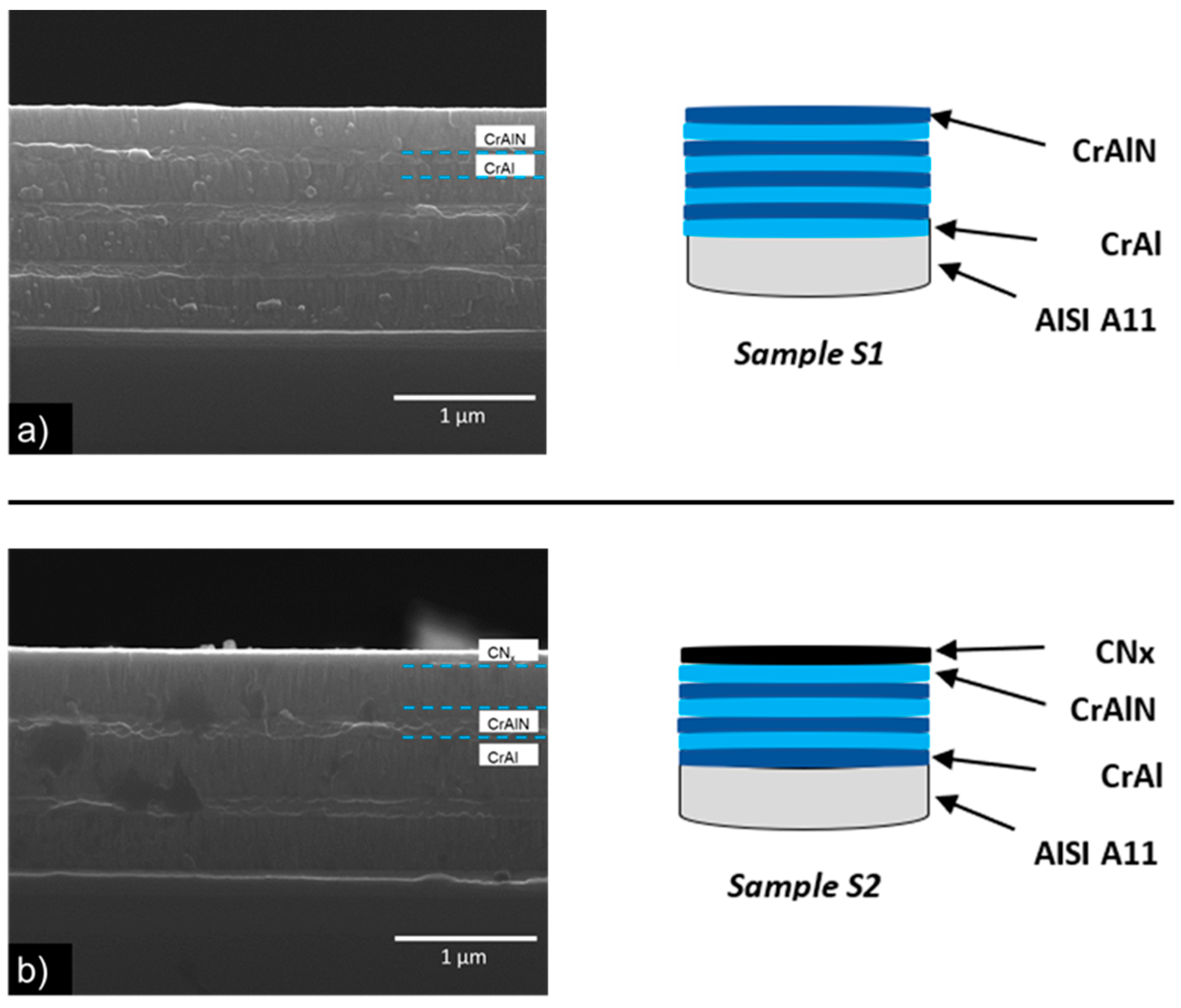
Multilayer coating thickness and morphology were determined by means of fracture cross-section of silicon substrates using secondary electron SEM images, as can be seen in Figure 3a,b for samples S1 and S2, respectively. Multilayer thickness for sample S1 was 1.5 μm, while sample S2 presented a total thickness of 1.2 μm. The CrAl phase showed a glassy morphology in both samples, with a (a-CNx) top layer in the S2 sample (see Figure 3b). Similar results have been reported in other studies [9,17,40,41]. However, the CrAlN phase presented the characteristic columnar morphology in both samples S1 and S2, as can be see in Figure 3a,b, respectively. Similar results were observed in CrAlN coatings deposited by HIPIMS [3,12]. For the root mean square roughness (Ra) measurement made of the top multilayer coatings, a total of 12 measurements were made to each sample. Results show a Ra = 0.03628 µm ± 0.0058 for sample S1, while for sample S2, the Ra = 0.02636 µm ± 0.0055; these changes in = roughness can be attributed to the (a-CNx) top layer, and the results agree well with others reported previously [35,42].
The chemical compositions of the bulk multilayer coatings are listed in Table 2. XRF results showed a light discrepancy for the Cr and Al concentrations between samples S1 and S2. This difference can be attributed to the different sputtering yields between the Cr and Al species when reactive atmosphere is deposited [9,43] and there are equipment limitations to quantifying light elements by XRF analysis.

3.2. Mechanical and Adhesion Properties

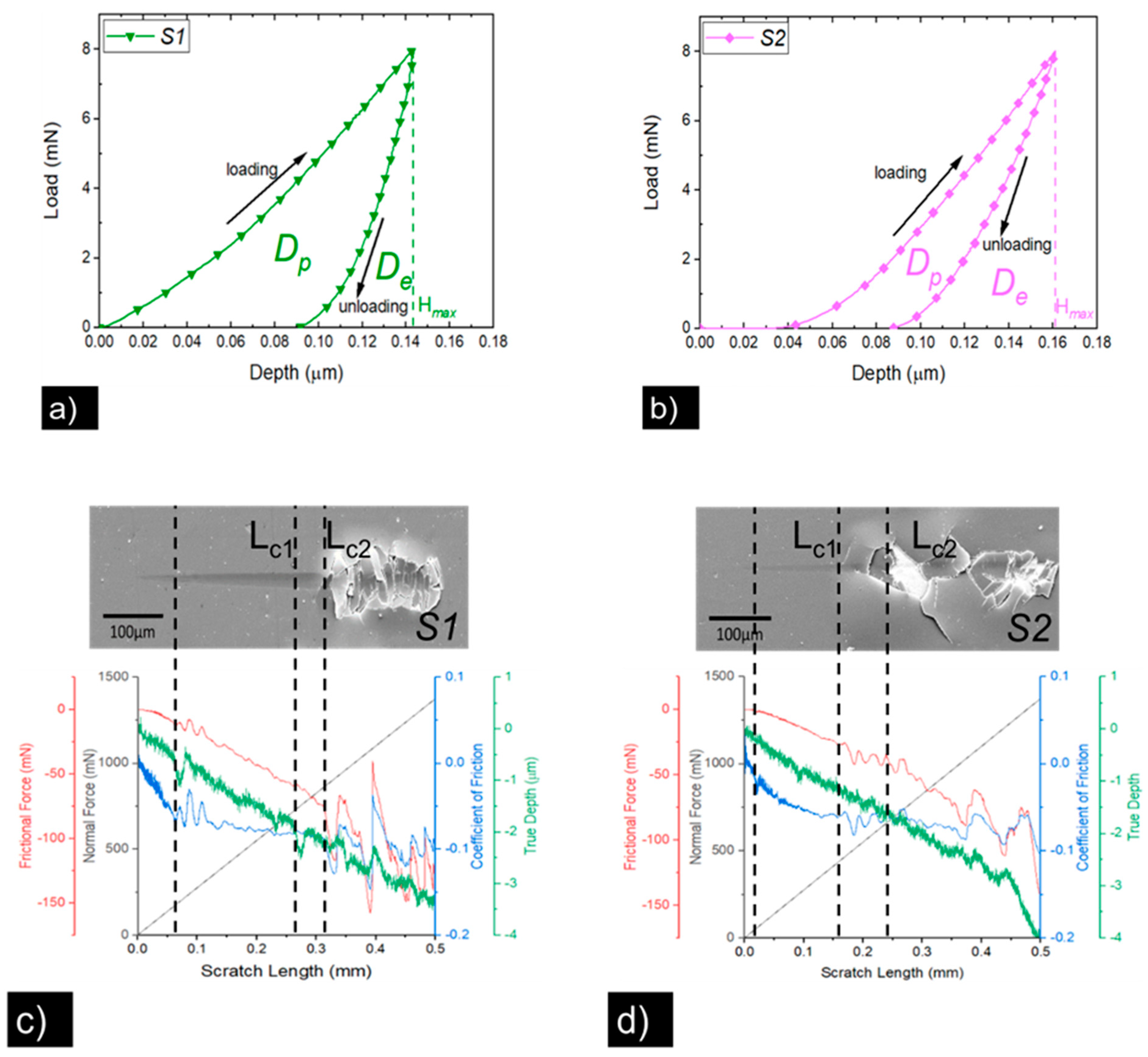
Results from the nanoindentation test showed hardness values of 23.08 ± 2.8 GPa and 20.58 ± 1.8 GPa for samples S1 and S2, respectively (see Figure 4a,b). The elastic modulus values were 508 ± 39.3 GPa and 397 ± 33.6 GPa for samples S1 and S2, respectively. Similar results (520 GPa) were reported for CrAlN coatings obtained with two targets of Cr and Al [7]. Table 3 shows the summarized values for mechanical properties. Similar hardness values were observed in other studies over monolayer CrAlN and multilayer CrAlN/CNx films obtained for HIPIMS and ion-beam-assisted magnetron sputtering [3,7,12,15]. As can be seen in some studies, hardness values, Young’s modulus, and toughness are related to the multilayer microstructure, as well as residual stress, which can increase the hardness due to the dislocation motion blocking. It has been seen that the CrAl layer increases the hardness of the CrAlN phase, which presents high elastic modulus [40]. So, alternating the layers of both phases improves the mechanical properties, and the increase in hardness can be explained by the Hall–Petch effect [44]. On the other hand, sample S2 shows a reduction in hardness values (10%), and the elastic modulus values of 22% can be compared to sample S1.
From the typical loading–unloading curve for these samples, the area between the loading and the unloading curve represents the energy dissipated into the film by the plastic deformation designated as Dp, while the area under the unloading curve represents the elastic energy deformation represented by De. The S1 sample had a mayor Dp area compared to the S2 sample, which could be attributed to its superior hardness (23.08 ± 2.8 GPa) compared to sample S2 (20.58 ± 1.8 GPa), where the (a-CNx) top layer and carbon morphology increased absorption energy capacity. The difference in hardness agreed well with the minor De area in sample S1 and the less mechanical potential energy stored can be attributed to the more ceramic content in its multilayer architecture. These results agreed well with the elastic recovery values (ER) obtained from Equation (1). Sample S1 showed a value of 36.24%, while sample S2 had a higher value of 45.75%. Moreover, the reduction in hardness and elastic modulus from the whole multilayer can be attributed to the (a-CNx) top layer morphology, in which similar values have been reported [40]. Mechanical resilience of multilayer films was extracted from H/Er relation, regarding the elastic and plastic behavior for these materials. According to obtained results, sample S2 presented a higher value of 0.0674 compared to the value of 0.0617 obtained in sample S1. This small increase in sample S2 can be attributed to the (a-CNx) top layer and its resilient capacity [18], and these results agree well with some studies that report low elastic modulus values and are associated to low coefficient friction [45], as was the case in sample S2.
Figure 4c,d shows the nano scratch test results for samples S1 and S2, respectively. Critical loads of crack initiation length (Lc1) and delamination length (Lc2) were extracted from electronic images and are indicated by dotted lines in the plotted graphics. Results are summarized in Table 4. The Lc1 varied from 0.729 N to 0.434 N for samples S1 and S2, respectively. According to these values, sample S1 presented the strongest scratch resistance, and in the same way, sample S1 showed the highest Lc2 value of 0.859 N while sample S2 presented a Lc2 value of 0.665 N. This difference could be attributed to the higher thickness and elastic modulus in sample S1 compared to S2.
Using Equations (2) and (3), adhesion energy and the critical stress for each coating are listed in Table 4. Here, the sample S1 showed the highest adhesion energy of 0.532 J/m2, while sample S2 showed only 0.253 J/m2. Adhesion strength in sample S1 corresponded to the largest coefficient of friction (0.086 > 0.056 µk), and similar results have been reported by several authors [46,47]. On the other hand, sample S1 presented higher roughness values than sample S2. Higher roughness could act like obstacles to movement of the indenter due to the high ridges and valleys, which increase the critical load (Lc2) [47,48]. These different roughness levels could increase the density of defects in the coating and at the interface, affecting the adhesion strength. Other studies reported that the adhesion to the substrate of the multilayer films decreased as the (a-CNx) sublayer thickness increased [49]. These results agree well with lower adhesion resistance observed in sample S2. Here, this lower adhesion resistance can be attributed to the residual stress generated in the CNx top layer, as has been reported in other studies [18,49].

3.3. Tribology Properties

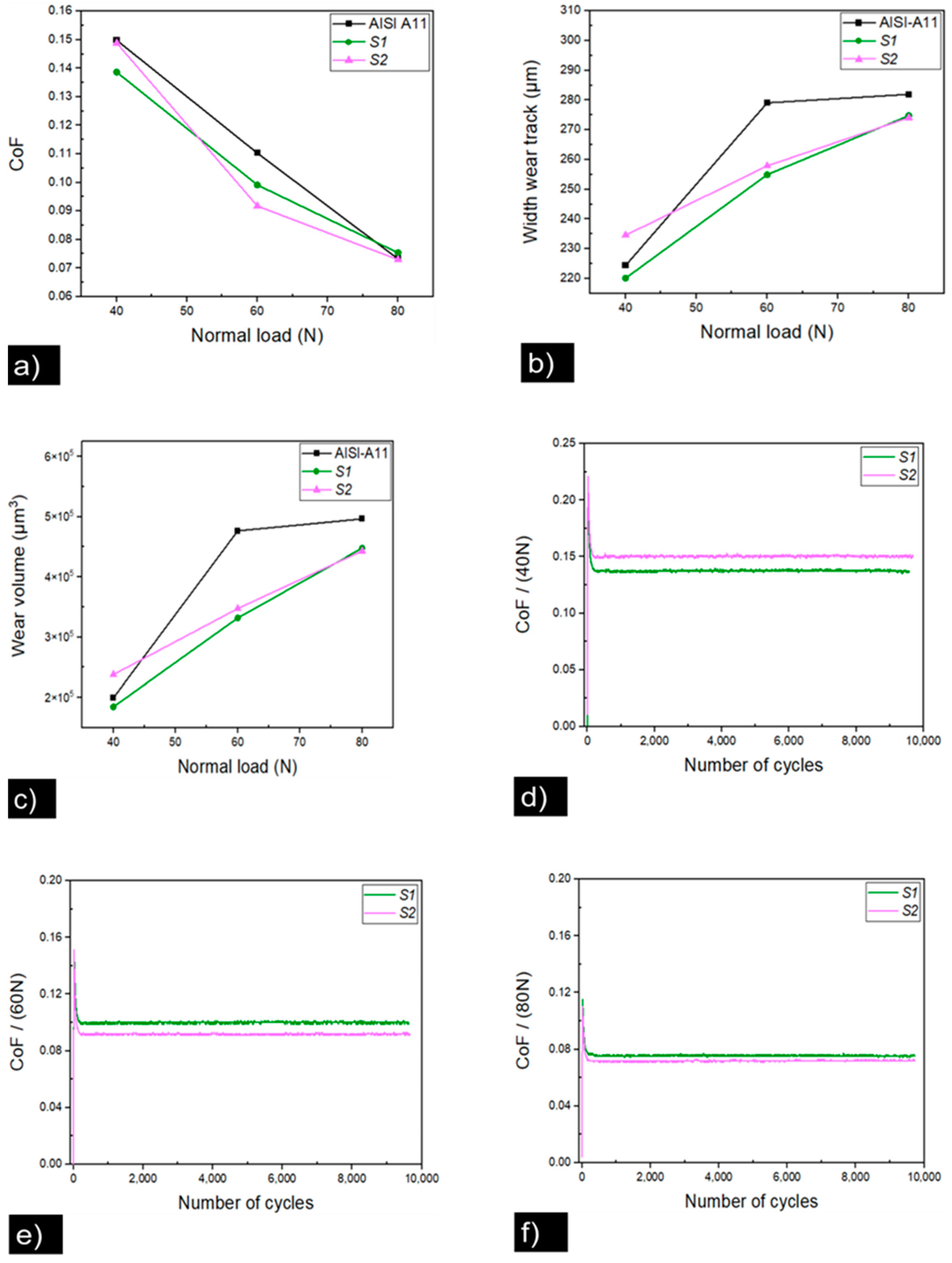
Figure 5a shows the plot corresponding to average CoF vs. applied load for samples S1 and S2, respectively. For an applied load of the 40 N sample, S1 showed a lower CoF value (0.13865 ± 0.00389 µk) compared to the S2 sample (0.14884 ± 0.00472 µk). When the applied load increased to 60 N, sample S2 showed an abrupt change in the CoF value (0.09175 ± 0.00336 µk) compared to sample S1 (0.09915 ± 0.0030 µk). Meanwhile, CoF values for sample S2 (0.07296 ± 0.00228 µk) and S1 (0.07537 ± 0.0025 µk) were close when a load of 80 N was applied. The width wear track for the fretting wear test is shown in Figure 5b, wherein sample S2 showed a higher value for width wear track (234.58 ± 6.7 µm) compared to sample S1 (220.13 ± 7.9 µm) tested with a normal load of 40 N. When a normal load of 60 N was applied, the difference in the width wear track (257.88 ± 8.4 µm) in sample S2 compared to sample S1 (254.91 ± 5.5 µm) was lower. Finally, sample S1 showed a higher value of (274.77 ± 3.9 µm) compared to the value for sample S2 (274.07 ± 3.4 µm) as soon as the normal load was increased to 80 N. As was observed, the coefficient of friction in fretting conditions decreased as normal load was increased (Figure 5a).
Otherwise, after low normal loads were applied, there was an elastic contact between the surface of the thin film and ball of alumina, hence the slip spread over the contact area. The debris detached during the wear process was trapped between the contact zone, increasing the coefficient of friction at low normal loads. Conversely, at high normal loads, the surface was under an elastic–plastic state, resulting in a low coefficient of friction, and as the wear track was in function of normal load, as it increased, the wear track increased. Similar results were observed in previous studies [50,51,52]. The wear volume as a function of normal loads is shown in Figure 5c, with lower values for sample S1 (1.84 × 10⁵ and 3.32 × 105 µm3, respectively) at normal loads of 40 and 60 N compared to sample S2 (2.38 × 10⁵ and 3.47 × 105 µm3, respectively). Similar values of wear volume (4.48 × 10⁵ and 4.43 × 105 µm3) were observed for samples S1 and S2, respectively, when a normal load of 80 N was applied. Figure 5d–f shows the CoF behavior for samples S1 and S2 vs. different cycles and a comparison for when normal load was increased. As can be seen, stable CoF behavior was observed for both samples during different cycles in the fretting wear test.
Figure 6a,b shows the FESEM wear track for sample S1, and we magnified the analyzed zone for the fretting wear test at 40 N. As can be seen, the wear track had an elliptical shape and showed a principal damage in the center of the track, with the main wear mechanism being delamination followed by partial ploughing and cracking. As can be seen in Figure 6c,d, an increment in the normal load to 60 N resulted in a concentric wear track with apparently less surface damage, mainly composed of ploughing and delamination. Finally, as shown in Figure 6e,f, when the normal load was 80 N, the wear track showed a displacement until it was stabilized. At the center of the wear track, no damage was seemingly observed, with only a crater wear mechanism. From the wear tracks (see Figure 6a–f) for different normal loads applied during the fretting test, it was evident that there was a change in the damage, width wear track, and wear mechanism, which agreed well with the change in CoF values reported above (see Figure 5a).
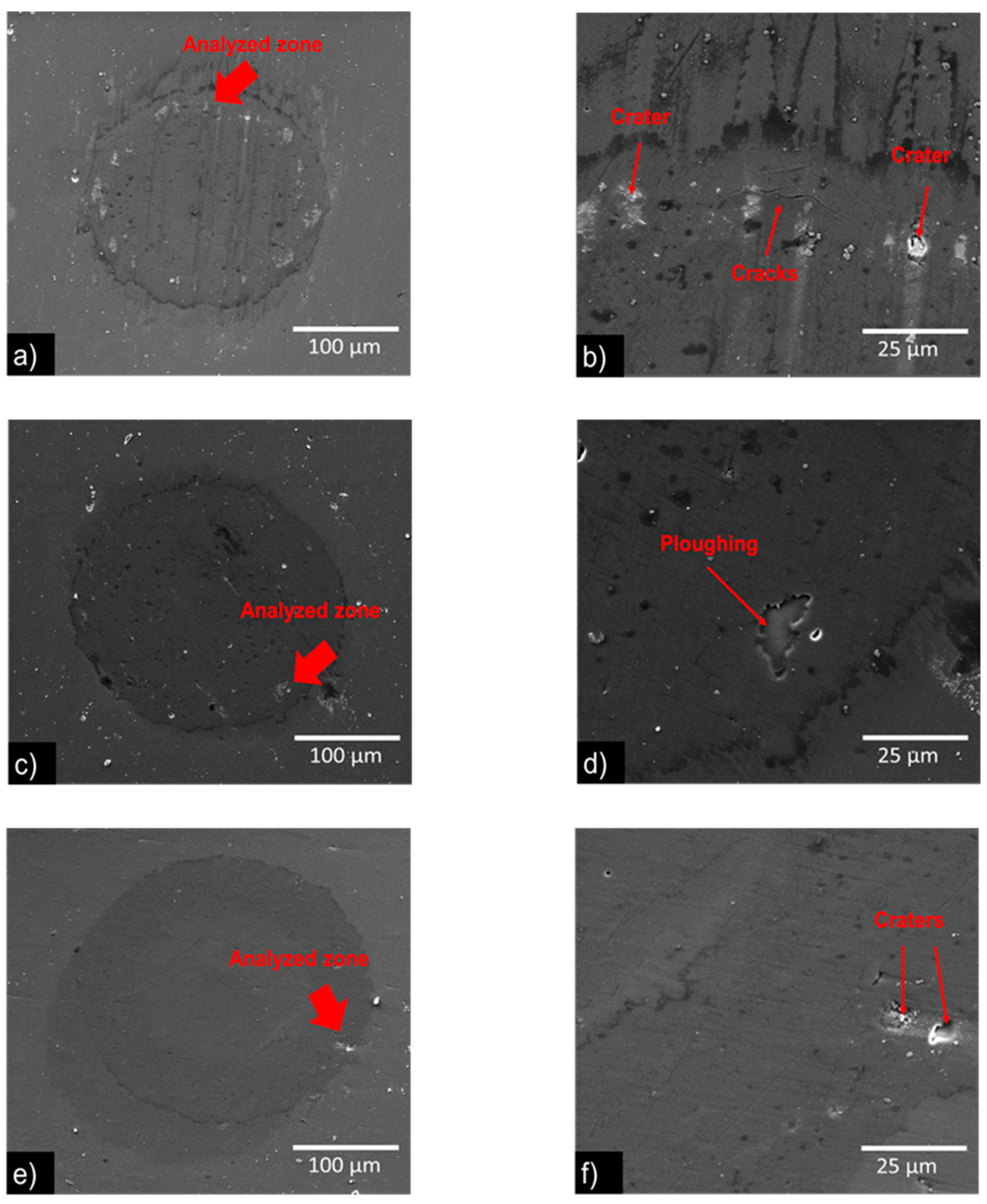
The FESEM images of wear track of sample S2 are shown in Figure 7. Under a normal load of 40 N, a concentric wear track is appreciated, and the main wear mechanism is crater formation followed by cracks, as can be seen in Figure 7a,b. When the load increased to 60 N, a similar shape wear track was observed, with a ploughing wear mechanism, as can be seen in Figure 7c,d. As the load increased to 80 N, the wear track was observed due to the ball displacement, and it diminished once the tests stabilized; however, no damage was seemingly observed, only a crater wear mechanism, as can be seen in Figure 7d,e. Compared to sample S1, the wear tracks for sample S2 showed less damage and regular shape during the fretting test, besides the lowest CoF values; however, this sample presented a larger width wear track that could be attributed to the slip spread contact area over the top (a-CNx) layer (see Figure 3b), which worked as a solid lubricant, decreasing the friction force between the surface in contact during the fretting wear test. It has been reported for micro tribological tests on (a-CNx) films that after cycles running the test, it contributes to the formation of a graphitic-like transfer film named a tribolayer, which helps to maintain the CoF value in a steady state; during the wear test, the same results were reported over (a-CNx) layer deposited by HIPIMS [53].
A way in which to see the aptness of tribology is through the relation (H/E) and resistance to plastic indentation (H3/E2) ratio based on nanoindentation results. As can be seen in Table 3, sample S2 showed higher values for H/E: 0.051 and H3/E2: 0.055, compared to sample S1, even for less multilayer thicknesses of 1.2 µm and 1.5 µm, respectively. These results agree well with other studies for CrAlN and (a-CNx) layers [2,3,7,42]. However, tribological properties in multilayer coatings depend on multiple factors such as microstructure, grain size, density, and residual stress.

3.3.1. Raman Characterization in Fretting Test

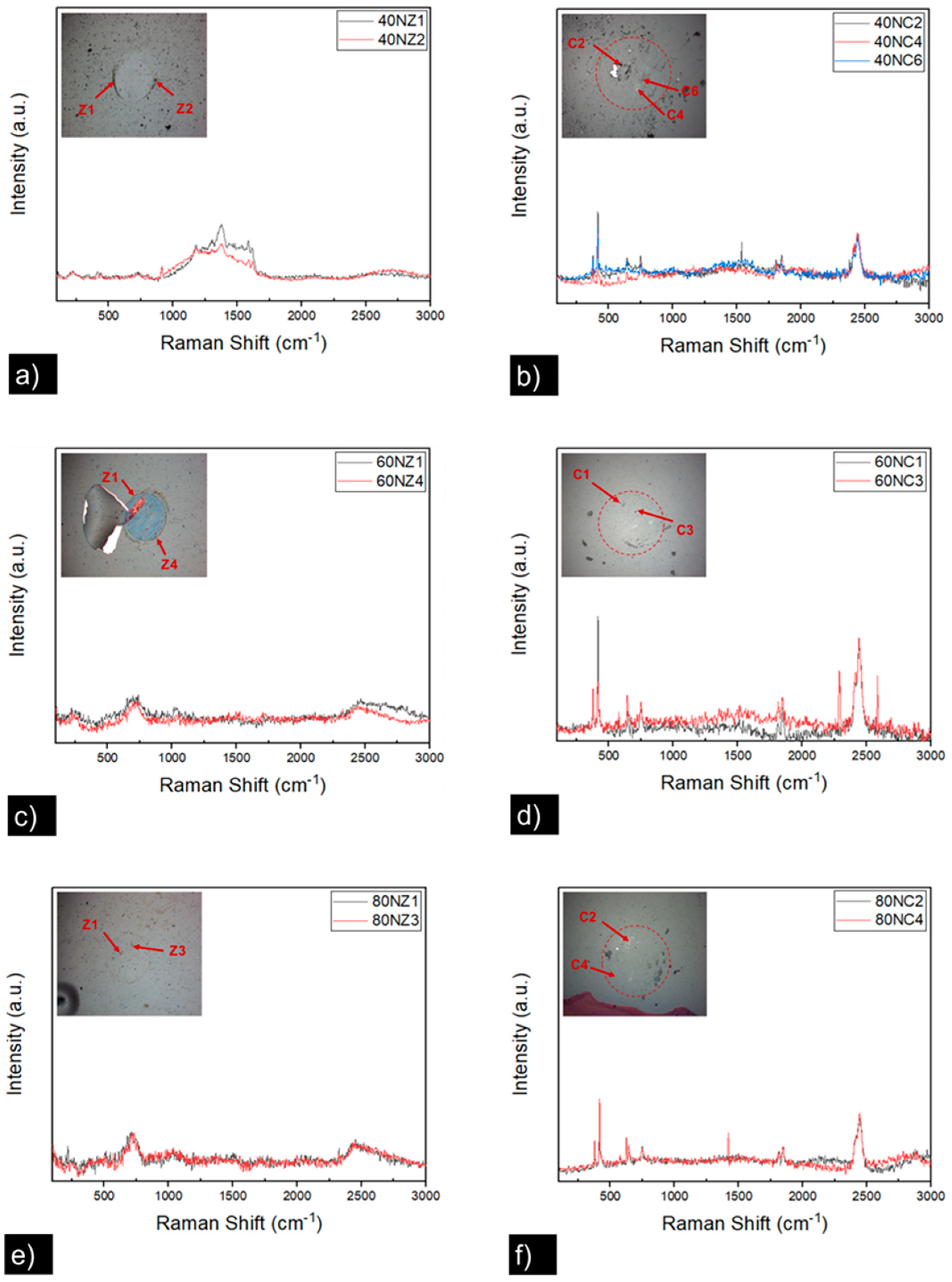
Figure 8a–f shows the Raman spectra analysis performed on the wear track surface for the sample S1 and the Al2O3 ball counter face after the fretting wear test. Figure 8a shows bands at higher numbers around 1400 cm−1 and 2400 cm−1, while as seen in Figure 8b, the Al2O3 counter face showed weak intense peaks around 400 cm−1, and others at 2400 cm−1. At a higher load of 60 N, the Raman spectra showed peaks for the wear track at 650 and 2400 cm−1, as can be seen in Figure 8c. The same peaks (400 and 2400 cm−1) were observed in the Al2O3 counter face, as is observed in Figure 8d. Finally, as seen in Figure 8e, Raman spectra corresponding to a normal load of 80 N was applied, showing peaks at 650 and 2400 cm−1, and Figure 8f shows the main peak at 2400 cm−1 for the Al2O3 counter face Raman spectra. Peaks values at 650 cm−1 at the wear track corresponding to CrAlN Raman spectra were associated with longitudinal and transversal optical vibrations (LO and TO) at 400–650 cm−1 [9]. Peaks at higher values arose via second-order transitions (A + O, 2O).
Meanwhile, higher peaks values of 2400 cm−1 at the counter face corresponded to the Al2O3 ball Raman spectra [54]; however, the weak peak of 400 cm−1 could be a CrAlN film added to the surface. The same case was observed in the Al2O3 counter face with a peak at 400 cm−1 that could be attributed to the CrAlN film added to the Al2O3 surface.
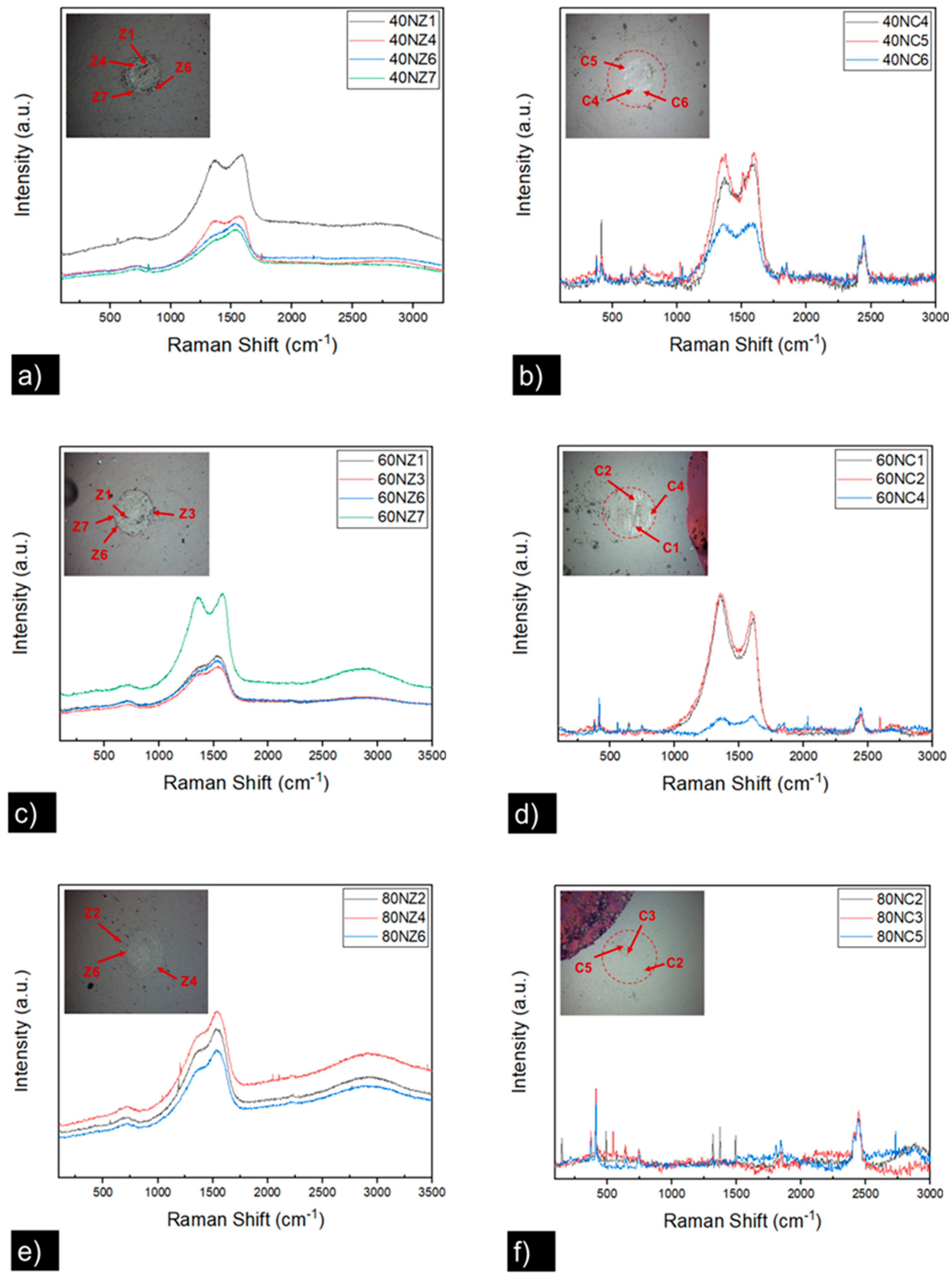
Raman spectra for sample S2 and the Al2O3 ball counter face are shown in Figure 9. When a normal load of 40 N was applied, as shown in Figure 9a, there were high-intensity peaks between 1350 and 1550 cm−1. Meanwhile, Figure 9b shows peaks for the Al2O3 counter face, with the same intensity peaks for 1350 to 1550 cm−1, followed by a peak at 2400 cm−1. When the normal load was increased to 60 N, as shown in Figure 9c, there were the same peaks between 1350 and 1550 cm−1 and a less intense peak at 2800 cm−1 in the wear track. As shown in Figure 9d, the Al2O3 counter face showed an intense peak between 1350 and 1550 cm−1 and a weak one at 2400 cm−1. An increment of 80 N in the normal load showed Raman spectra for the wear track seen in Figure 9e, with peaks between 1350 and 1550 cm−1 and at 2800 cm−1. Lastly, the Al2O3 counter face showed only a peak at 2400 cm−1, as was observed in Figure 9f, with no residue transfer of CNx observed. This could be attributed to the CNx top layer turned into small traces that were not adhered to the Al2O3 counter face. Otherwise, Raman intensity peaks between 1350 and 1550 cm−1 are characteristics of thin films for a-CNx [18] (see Figure 2b), and those at 2800 cm−1 correspond with the Al2O3 ball of Raman spectra [54]. The characteristic peaks for (a-CNx) detected in the Al2O3 counter face can be attributed to the tribo-layer formed during the fretting tests, which agrees with the wear volume removed during the test at 40 and 60 N normal loads, as can be seen in Figure 5c.
Figure 10 shows the typical Raman spectra subtracted from worn surfaces for sample S2 (see Figure 9) tested at 40, 60, and 80 N, compared to the deposited top layer (a-CNx) with the deconvoluted peaks D and G. As can be seen, Raman spectra obtained of the worn surface tested at 40 N showed similar intensity for peaks D and G. The profile fitting results indicate that the value of I(D)/I(G) increased from 0.94 to 0.96.
On the other hand, Raman spectra of the worn surface obtained at 60 N showed a noticeable change in the intensity peaks D and G, compared to the as-deposited (a-CNx) top layer, with a I(D)/I(G) ratio of 1.13. The increment of the I(D)/I(G) ratio can be attributed to the formation of the carbon sp2 structure (i.e., graphite-like structure), with previous studies having reported the same results [55], wherein this carbon structure is beneficial to low-friction coefficients (<0.10) for carbon-based coatings [18,37,56]. Finally, no Raman spectra were observed in the Al2O3 ball worn surface during the fretting test at 80 N, as can be seen in Figure 9f. This absence of transfer material from the CNx layer can be attributed to the wear contact during the fretting test (see Figure 7e) and its fretting regime, which is detailed in the next section.

3.3.2. Fretting Regime

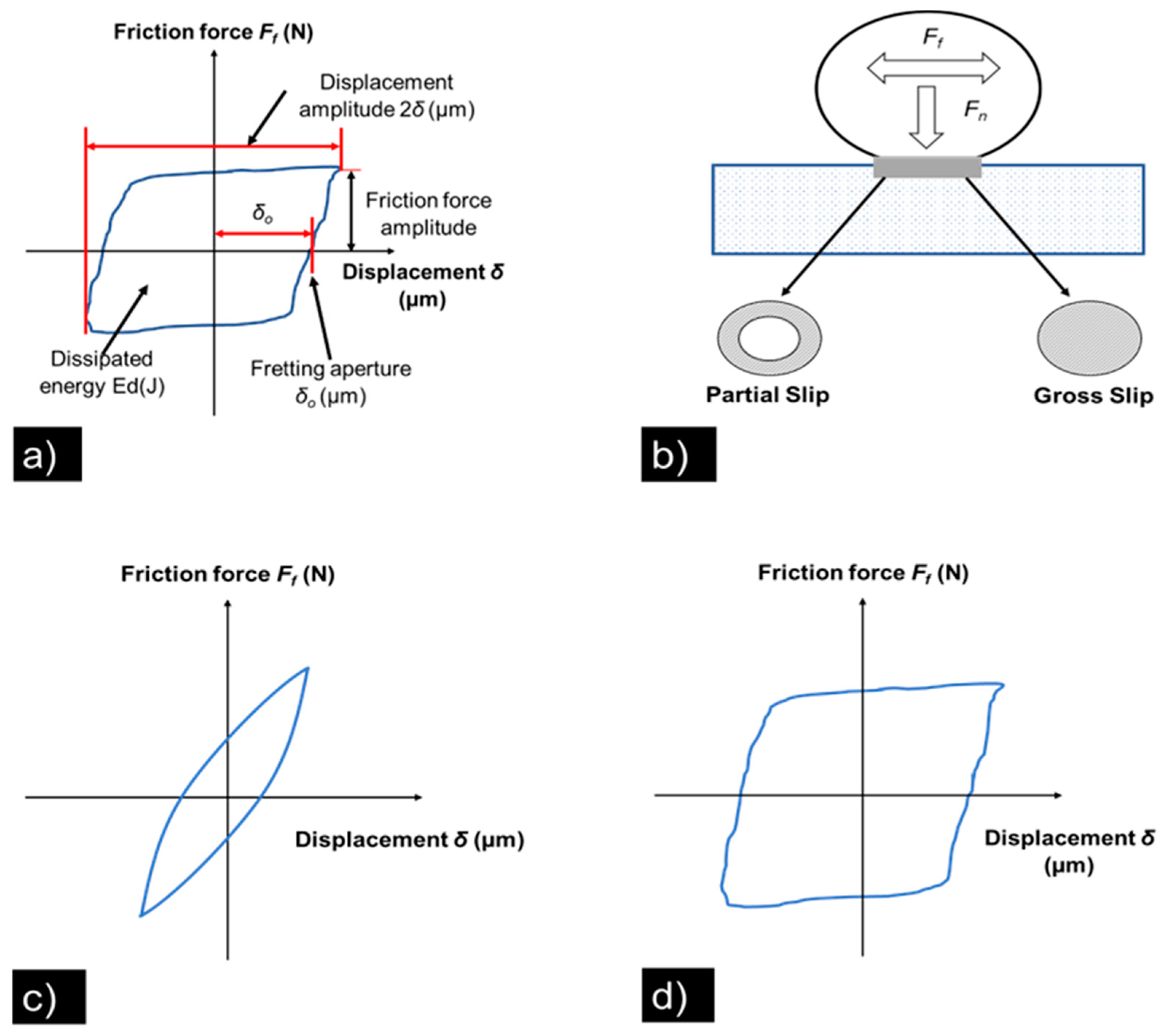
The fretting maps and fretting loops are used to characterize the contact conditions at the contact interface [57,58]. Figure 11a,b defines each parameter for a complete fretting loop [30], which are related with the friction force and displacement amplitude. Meanwhile, Figure 11b,c shows a schematic of the fretting wear regime of contact, which are partial slip and gross-slip, respectively. Moreover, the area of the fretting loop can be calculated to determine the dissipated energy due to friction (which corresponds to wear volume according to the dissipated energy wear model) [59,60].
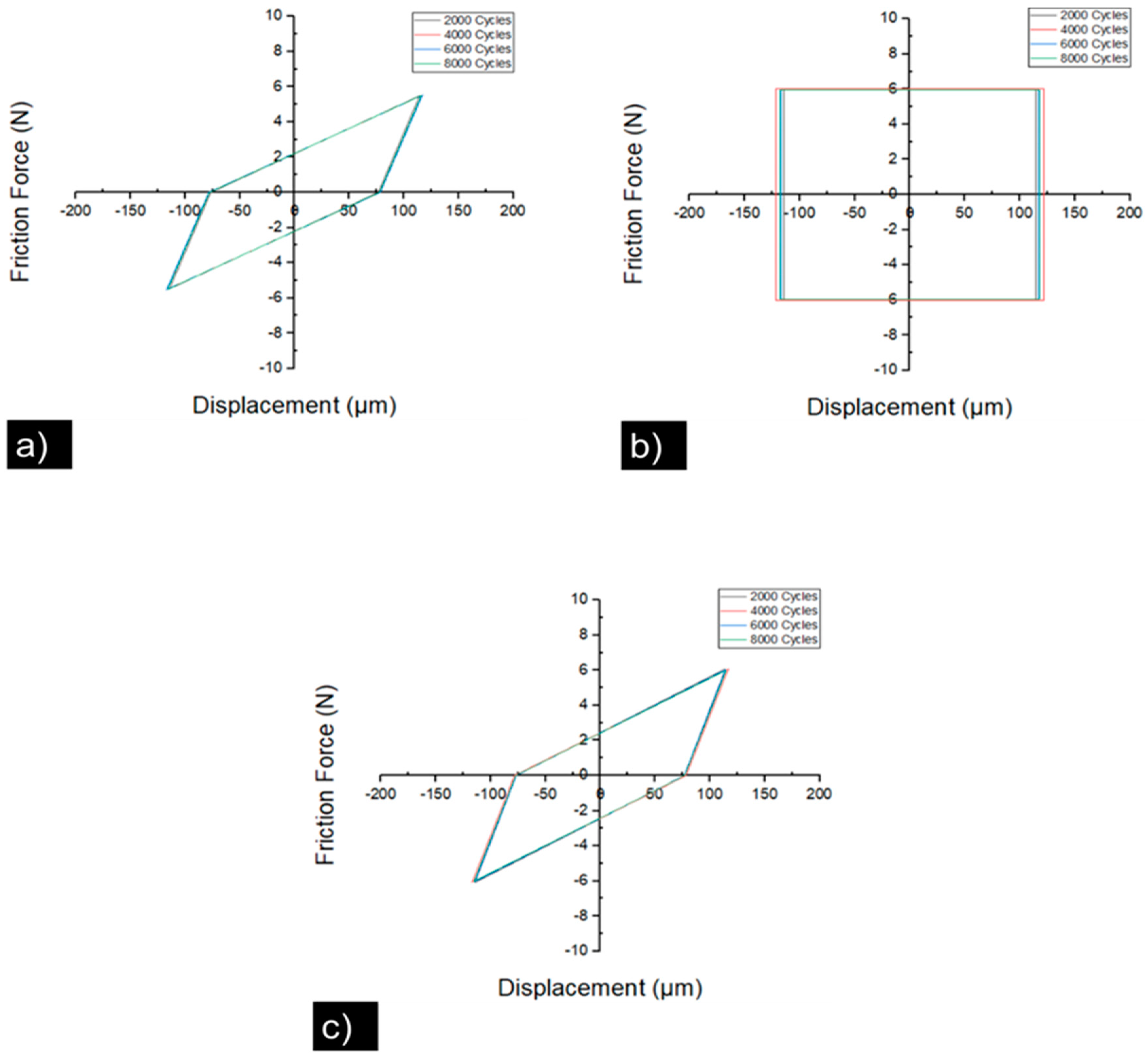
Figure 12a displays the fretting loop for sample S1 tested at 40 N of normal load for different cycles (2000, 4000, 6000, and 8000). As can be seen, the fretting loop shape corresponded to a partial slip regime. This agrees well with the contact wear track observed in Figure 6a. Figure 12b shows a fretting loop shape for a normal load of 60 N, which is in accordance with a gross slip regime that agrees well with the wear track observed in Figure 6c. It is evident that there was a variation displacement during the fretting test against different cycles. Finally, Figure 12c presents the fretting loop for a higher normal load of 80 N, wherein the regime changed again to a partial slip, and its respective wear track corresponded to this regime (see Figure 6e) [52].
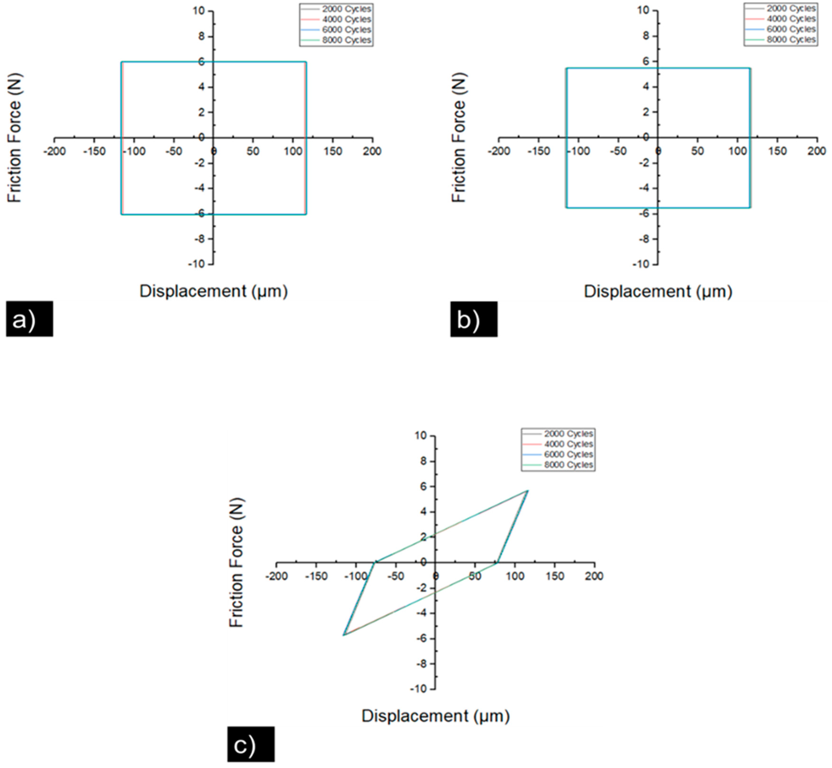
Figure 13 exhibits the fretting loops corresponding to sample S2. As can be seen in Figure 13a, there was a gross slip regime when a normal load of 40 N was applied, and the wear track agreed well with this result (see Figure 7a). A few variations of displacement were observed during fretting tests at different cycles. For a normal load of 60 N, Figure 13b exposes a fretting loop with the same gross slip regime and its respective agreement with the wear track (see Figure 7c). When the maximum load of 80 N was applied, the fretting loop regime changed to a partial slip, as is observed in Figure 13c; the wear track observed in Figure 7e agrees well with this fretting regime [52]. Table 5 shows the dissipated energy (J/m), where sample S1 had the highest energies for all the normal loads applied. It was demonstrated that wear volume is linearly related to dissipated energy, but changes of tribochemistry in the contact resulted in a modification in the wear rate [60]. The sample S1 shows the lowest wear volume compared with sample S2, as can be seen in Figure 5c. This different behaviors between higher wear volume and lowest dissipated energy observed in sample S2 can be attributed to the tribolayer formatted during the fretting tests, the formation of carbon sp2 structure [55], and its ability to lower the friction coefficient (<0.10) for carbon-based coatings [18,37,56], as already has been discussed previously.
For the same applied displacement, a Δ of 150 μm was measured for different slip amplitudes 2δ, and these behaviors can be explained according to Vingsbo and Doderberg [61]. Here, the partial slip loop is related to a closed (δ-Ff) cycle. In this regime, the contact area is divided into a sticking zone in the center of the contact and sliding zones at the edges, which can be observed in sample S1 when normal loads of 40 and 80 N were applied during the fretting test (see Figure 12a,c) [61]. This behavior can be related to the wear track observed in Figure 6a,e. Alternatively, the same behavior was observed in the fretting loop (see Figure 13c) when a normal load of 80 N was applied in sample S2, and it agreed with the wear track observed in Figure 7e and with the absence of transfer material from the CNx layer to the Al2O3 ball, as can be seen in Figure 9f. On the other hand, in the gross slip regime, all the (δ-Ff) cycles were quasi-rectangular loops (see Figure 13a,b). In this regime, there were higher displacement amplitudes. The sticking zone no longer existed and the whole contact was under full reciprocating sliding [61]. As can be seen, this behavior corresponded with the wear track shown in Figure 7a,c.
Experimental loops usually do not match well with the idealized shape, due to wear conditions and calculations not being simple [61]. Variables such as normal force F, friction force Ff, and the micro-slip at point in contact δ affect the obtention of fretting loops. Then, to overcome these problems, tribometers are equipped with a force transducer combinate with force actuators to measure the contact load during the fretting test [61]. In the fretting loop calculations, the tangential contact stiffness is defined by slope of the partial slip regime; however, this partial slip and contact interface is considered the most difficult variable to measure during the fretting testing. So, the slip amplitude δ0 at each contact point is unknown during the fretting test, and sometimes this measurement is extrapolated from the displacement amplitude 2δ [61]. In other cases, slip amplitude measurements are performed between two reference points relatively far away from the contact. Finally, in some cases, the measurements were made between the specimen fixtures or directly from the displacement applied on the actuators [61]. In this study, these measurements were limited due to the configuration of the tribometer; nonetheless, fretting loops were obtained according to these implications.

4. Conclusions

The CrAl/CrAlN and CrAl/CrAlN-(a-CNx) coatings were successfully deposited by the HIPIMS technique. The following conclusions can be summarized:
XRD characterization showed a cubic structure and orientations of (111), (200), (220), and (222) for CrAl/CrAlN coatings in samples S1 and S2. FE-SEM analysis confirmed a glass-like morphology in the CrAl layer and in the (a-CNx) top layer, while the CrAlN layers exhibited a columnar morphology. This morphology made a difference in Ra values for sample S1 compared to S2 (0.03628 µm ± 0.0058 and 0.02636 µm ± 0.0055, respectively). Chemical composition confirms the presence of Cr and Al into the CrAl/CrAlN and CrAl/CrAlN-(a-CNx) multilayers.
Nanoindentation results showed a higher hardness in sample S1 compared to sample S2; however, sample S2 with the (a-CNx) top layer increased the absorption energy capacity and its mechanical potential energy stored, represented by the elastic recovery values. Moreover, sample S2 showed the higher value for tribology aptness for the (H/E) relation, as well as resistance to plastic deformation by the (H3/E2) ratio.
Nano scratch test results on sample S1 show the highest adhesion resistance and highest adhesive energy values, corresponding with the main coefficient of friction during the test and agreeing well with the higher values of the energy dissipated during the nanoindentation test, as well as its major architecture periodicity (1.5 ± 0.06 µm in thickness).
Sample S2 showed lower CoF values during fretting tests, due to the interaction of the a-CNx top layer with the counterbody and its capacity to form a tribolayer; the transfer material to the ball was confirmed by Raman spectroscopy. The Raman spectra subtracted from worn surfaces during the fretting test and the (D)/I(G) ratio showed an increase in the I(D)/I(G) ratio for sample S2 tested at 40 N and 60 N, attributed to the formation of carbon sp2 structure (i.e., graphite-like structure) beneficial to low-friction coefficients (<0.10) for carbon-based coatings.
The CrAl/CrAlN and CrAl/CrAlN-(a-CNx) multilayers with thicknesses of 1.5 ± 0.06 and 1.2 ± 0.05 µm, respectively, proposed in this investigation improved the mechanical and tribological property behavior of the AISI A11 steel substrate and can be used as a potential protective surface for forms of moving parts such as gears, cutting tools, and shafts used in engines. Further studies must be done around plasma species characterization through optical emission spectroscopy (OES) and its comparison between sectioned targets with the alloyed target Cr-Al (0.50:0.50).

Author Contributions

C.J.M.-G.: methodology, investigation, writing—original draft. M.F.F.-J.: formal analysis, project administration. D.I.B.-B.: formal analysis, data curation, O.J.-A.: resources, supervision, writing—review and editing. M.F.-M.: resources, supervision, writing—review and editing. All authors have read and agreed to the published version of the manuscript.

Funding

This research was funded by Universidad de Guadalajara and Consejo Nacional de Ciencia y Tecnología (CONACYT), Frontiers of Science Program (Project 1103).

Institutional Review Board Statement

Not applicable.

Informed Consent Statement

Not applicable.

Data Availability Statement

Not applicable.

Acknowledgments

Cecilio J. Martínez-Gonzalez wants to thank the Programa de Doctorado en Ciencia de Materiales, Centro Universitario de Ciencias Exactas e Ingenierías (CUCEI), and the Maestría en Ciencia e Ingeniería de los Materiales, Universidad Autónoma de Zacatecas.

Conflicts of Interest

The authors declare no conflict of interest.

References

  1. Ding; X.Z.; Zeng, X.T.; Liu, Y.C.; Fang, F.Z.; Lim, G.C. Cr1-xAlxN coatings deposited by lateral rotating cathode arc for high speed machining applications. Thin Solid Film. 2008, 516, 1710–1715. [Google Scholar] [CrossRef]
  2. Wang, L.; Zhang, G.; Wood, R.J.K.; Wang, S.C.; Xue, Q. Fabrication of CrAlN nanocomposite films with high hardness and excellent anti-wear performance for gear application. Surf. Coat. Technol. 2010, 204, 3517–3524. [Google Scholar] [CrossRef]
  3. Tang, J.F.; Lin, C.Y.; Yang, F.C.; Chang, C.L. Influence of nitrogen content and bias voltage on residual stress and the tribological and mechanical properties of CrAlN films. Coatings 2020, 10, 546. [Google Scholar] [CrossRef]
  4. Berg, G.; Friedrich, C.; Broszeit, E.; Berger, C. Development of chromium nitride coatings substituting titanium nitride. Surf. Coat. Technol. 1996, 86, 184–191. [Google Scholar] [CrossRef]
  5. Khamseh, S.; Nose, M.; Kawabata, T.; Saiki, A.; Matsuda, K.; Terayama, K.; Ikeno, S. Effect of deposition conditions on the structure and properties of CrAlN films prepared by pulsed DC reactive sputtering in FTS mode at high Al content. Mater. Trans. 2008, 49, 2082–2090. [Google Scholar] [CrossRef] [Green Version]
  6. Khamseh, S.; Nose, M.; Ueda, S.; Kawabata, T.; Nagae, T.; Matsuda, K.; Ikeno, S. Nanostructured CrAlN Films Prepared at Different Pulse Widths by Pulsed DC Reactive Sputtering in Facing Target Type System. Mater. Trans. 2008, 49, 0810100573. [Google Scholar] [CrossRef] [Green Version]
  7. Nouveau, C.; Tlili, B.; Aknouche, H.; Benlatreche, Y.; Patel, B. Comparison of CrAlN layers obtained with one (CrAl) or two targets (Cr and Al) by magnetron sputtering. Thin Solid Film. 2012, 520, 2932–2937. [Google Scholar] [CrossRef] [Green Version]
  8. Tsai, S.H.; Duh, J.G. Microstructure and Corrosion Properties of Multilayered CrAlN/SiNx Coatings. J. Electrochem. Soc. 2010, 157, K89. [Google Scholar] [CrossRef]
  9. Ipaz, L.; Aperador, W.; Caicedo, J.; Esteve, J.; Zambrano, G. A Practical Application of X-ray Spectroscopy in Ti-Al-N and Cr-Al-N Thin Films. In X-ray Spectroscopy; InTech: Shanghai, China, 2012. [Google Scholar] [CrossRef] [Green Version]
  10. Kaouther, K.; Hafedh, D.; Lassaad, Z.; Ahmed, B.C.L. Mechanical Characterization of CrN/CrAlN Multilayer Coatings Deposited by Magnetron Sputtering System. J. Mater. Eng. Perform. 2015, 24, 4077–4082. [Google Scholar] [CrossRef]
  11. Paulitsch, J.; Schenkel, M.; Zufraß, T.; Mayrhofer, P.H.; Münz, W.D. Structure and properties of high power impulse magnetron sputtering and DC magnetron sputtering CrN and TiN films deposited in an industrial scale unit. Thin Solid Film. 2010, 518, 5558–5564. [Google Scholar] [CrossRef]
  12. Bobzin, K.; Brögelmann, T.; Kruppe, N.C.; Engels, M.; Von Keudell, A.; Hecimovic, A.; Ludwig, A.; Grochla, D.; Banko, L. Fundamental study of an industrial reactive HPPMS (Cr, Al)N process. J. Appl. Phys. 2017, 122, 015302. [Google Scholar] [CrossRef]
  13. Wu, Z.; Cheng, Z.; Zhang, H.; Xu, Z.; Wang, Y.; Zhou, F. Electrochemical and Tribological Properties of CrAlN, TiAlN, and CrTiN Coatings in Water-Based Cutting Fluid. J. Mater. Eng. Perform. 2020, 29, 2153–2163. [Google Scholar] [CrossRef]
  14. Wang, X.; Kwon, P.Y.; Schrock, D.; Kim, D. Friction coefficient and sliding wear of AlTiN coating under various lubrication conditions. Wear 2013, 304, 67–76. [Google Scholar] [CrossRef]
  15. Liu, D.; Ma, H.; Li, H.; Liang, Y. Structure, phase transformation and corrosion resistance of CrAlN/CNx composite multilayer films in NaCl aqueous solution. Ceram. Int. 2019, 45, 24446–24452. [Google Scholar] [CrossRef]
  16. Tillmann, W.; Dias, N.F.L.; Stangier, D. Tribo-mechanical properties of CrC/a-C thin films sequentially deposited by HiPIMS and mfMS. Surf. Coat. Technol. 2018, 335, 173–180. [Google Scholar] [CrossRef]
  17. Bakoglidis, K.D.; Schmidt, S.; Greczynski, G.; Hultman, L. Improved adhesion of carbon nitride coatings on steel substrates using metal HiPIMS pretreatments. Surf. Coat. Technol. 2016, 302, 454–462. [Google Scholar] [CrossRef]
  18. Bakoglidis, K.D.; Schmidt, S.; Garbrecht, M.; Ivanov, I.G.; Jensen, J.; Greczynski, G.; Hultman, L. Low-temperature growth of low friction wear-resistant amorphous carbon nitride thin films by mid-frequency, high power impulse, and direct current magnetron sputtering. J. Vac. Sci. Technol. A Vac. Surf. Film. 2015, 33, 05E112. [Google Scholar] [CrossRef] [Green Version]
  19. Bakoglidis, K.D.; Glenat, H.; Greczynski, G.; Schmidt, S.; Grillo, S.; Hultman, L.; Broitman, E. Comparative study of macro- and microtribological properties of carbon nitride thin films deposited by HiPIMS. Wear 2017, 370–371, 1–8. [Google Scholar] [CrossRef]
  20. Terek, P.; Kukuruzović, D.; Kovačević, L.; Miletić, A.; Terek, V.; Škorić, B.; Panjan, P.; Čekada, M. The Influence of CrAlN Coating Chemical Composition on Soldering Resistance in Contact with Al-Si-Cu Alloy. Mater. Proc. 2020, 2, 28. [Google Scholar] [CrossRef]
  21. Oliver, W.C.; Pharr, G.M. An improved technique for determining hardness and elastic modulus using load and displacement sensing indentation experiments. J. Mater. Res. 1992, 7, 1564–1583. [Google Scholar] [CrossRef]
  22. Chang, S.Y.; Huang, Y.C. Analyses of interface adhesion between porous SiO2 low-k film and SiC/SiN layers by nanoindentation and nanoscratch tests. Microelectron. Eng. 2007, 84, 319–327. [Google Scholar] [CrossRef]
  23. Chang, S.-Y.; Lee, Y.-S.; Lu, C.-L. Effect of Plasma Treatments on the Interface Chemistry and Adhesion Strength Between Cu Metallization and SiCN Etch Stop Layer. J. Electrochem. Soc. 2007, 154, D241. [Google Scholar] [CrossRef]
  24. Huang, Y.C.; Chang, S.Y.; Chang, C.H. Effect of residual stresses on mechanical properties and interface adhesion strength of SiN thin films. Thin Solid Film. 2009, 517, 4857–4861. [Google Scholar] [CrossRef]
  25. Wang, Q.; Zhou, F.; Yan, J. Evaluating mechanical properties and crack resistance of CrN, CrTiN, CrAlN and CrTiAlN coatings by nanoindentation and scratch tests. Surf. Coat. Technol. 2016, 285, 203–213. [Google Scholar] [CrossRef]
  26. Mayrhofer, P.H.; Music, D.; Reeswinkel, T.; Fuß, H.G.; Schneider, J.M. Schneider, Structure, elastic properties and phase stability of Cr1−xAlxN. Acta Mater. 2008, 56, 2469–2475. [Google Scholar] [CrossRef]
  27. Champi, A.; Lacerda, R.G.; Marques, F.C. Thermomechanical properties of the amorphous carbon nitride thin films. Microelectron. J. 2003, 34, 553–555. [Google Scholar] [CrossRef]
  28. Dong, H.; Oganov, A.R.; Zhu, Q.; Qian, G.R. The phase diagram and hardness of carbon nitrides. Sci. Rep. 2015, 5, 9870. [Google Scholar] [CrossRef] [Green Version]
  29. Liu, X.L.; Li, Z.H.; Xiao, Q.; Yang, W.B.; Chen, D.Y. Fretting Wear of Co-Cr-Mo Alloys at Elevated Temperatures. J. Mater. Eng. Perform. 2020, 29, 7499–7510. [Google Scholar] [CrossRef]
  30. Vincent, L.; Berthier, Y.; Godet, M. Testing Methods in Fretting Fatigue: A Critical Appraisal; ASTM International: West Conshohocken, PA, USA, 1992; Volume 1159, pp. 33–48. [Google Scholar]
  31. Panjan, P. Industrial applications of CrN (PVD) coatings, deposited at high and low temperatures. Surf. Coat. Technol. 1997, 97, 182–191. [Google Scholar]
  32. Kong, J.Z.; Hou, T.J.; Wang, Q.Z.; Yin, L.; Zhou, F.; Zhou, Z.F.; Li, L.K.Y. Influence of titanium or aluminum doping on the electrochemical properties of CrN coatings in artificial seawater. Surf. Coat. Technol. 2016, 307, 118–124. [Google Scholar] [CrossRef]
  33. Quintero, O.M.S.; Chaparro, W.A.; Ipaz, L.; Barco, J.E.S.; Beltrán, F.E.; Zambrano, G. Influence of the microstructure on the electrochemical properties of Al-Cr-N coatings deposited by Co-Sputtering method from a Cr-Al binary target. Mater. Res. 2013, 16, 204–214. [Google Scholar] [CrossRef] [Green Version]
  34. Baseri, N.A.; Mohammadi, M.; Ghatee, M.; Abassi-Firouzjah, M.; Elmkhah, H. The effect of duty cycle on the mechanical and electrochemical corrosion properties of multilayer CrN/CrAlN coatings produced by cathodic arc evaporation. Surf. Eng. 2021, 37, 253–262. [Google Scholar] [CrossRef]
  35. Lv, Y.; Ji, L.; Liu, X.; Li, H.; Zhou, H.; Chen, J. The structure and properties of CrAlN films deposited by mid-frequency unbalanced magnetron sputtering at different substrate bias duty cycles. Surf. Coat. Technol. 2012, 206, 3961–3969. [Google Scholar] [CrossRef]
  36. Mohammadpour, E.; Jiang, Z.T.; Altarawneh, M.; Mondinos, N.; Rahman, M.M.; Lim, H.N.; Huang, N.M.; Xie, Z.; Zhou, Z.F.; Dlugogorski, B.Z. Experimental and predicted mechanical properties of Cr1−xAIxN thin films, at high temperatures, incorporating in situ synchrotron radiation X-ray diffraction and computational modelling. RSC Adv. 2017, 7, 22094–22104. [Google Scholar] [CrossRef] [Green Version]
  37. Zheng, X.H.; Yang, F.E.; Chen, L.; Chen, Z.L.; Song, R.G.; Zhang, X.H. Microstructure and mechanical properties of a-CNx films prepared by bias voltage assisted PLD with carbon nitride target. Surf. Coat. Technol. 2014, 258, 716–721. [Google Scholar] [CrossRef]
  38. Ferrari, A.C.; Rodil, S.E.; Robertson, J. Interpretation of infrared and Raman spectra of amorphous carbon nitrides. Phys. Rev. B 2003, 67, 155306. [Google Scholar] [CrossRef] [Green Version]
  39. Ferrari, A.; Robertson, J. Interpretation of Raman spectra of disordered and amorphous carbon. Phys. Rev. B—Condens. Matter Mater. Phys. 2000, 61, 14095–14107. [Google Scholar] [CrossRef] [Green Version]
  40. Zhao, Z.; Miao, Q.; Liang, W.; Xia, J.; Lin, H.; Qi, Y.; Zuo, S. Effect of CrAl interlayer on adhesion strength of CrAlN coating. Surf. Eng. 2020, 36, 438–446. [Google Scholar] [CrossRef]
  41. Pérez-Alvarez, J.; Flores-Jiménez, M.; Rivera-Tello, C.D.; Suárez-Martínez, R.; Jimenez, O.; Flores-Cova, L.; Flores, M. Effect of a-CNx top layer on the electrochemical properties of Ta2N/Ta multilayers obtained by HIPIMS. Mater. Lett. 2020, 278, 128454. [Google Scholar] [CrossRef]
  42. Zhou, F.; Adachi, K.; Kato, K. Comparisons of tribological property of a-C, a-CNx and BCN coatings sliding against SiC balls in water. Surf. Coat. Technol. 2006, 200, 4471–4478. [Google Scholar] [CrossRef]
  43. Laegreid, N.; Wehner, G.K. Sputtering yields of metals for ar+ and ne+ ions with energies from 50 to 600 ev. J. Appl. Phys. 1961, 32, 365–369. [Google Scholar] [CrossRef]
  44. Lv, F.; Wen, S.P.; Zong, R.L.; Zeng, F.; Gao, Y.; Pan, F. Nanoindentation study of amorphous-Co79Zr13Nb8/Cr multilayers. Surf. Coat. Technol. 2008, 202, 3239–3245. [Google Scholar] [CrossRef]
  45. Horwat, D.; Jimenez-Pique, E.; Pierson, J.F.; Migot, S.; Dehmas, M.; Anglada, M. High hardness, low Youngs modulus and low friction of nanocrystalline ZrW2 Laves phase and Zr1−xWx thin films. J. Phys. Chem. Solids 2012, 73, 554–558. [Google Scholar] [CrossRef]
  46. Kataria, S.; Kumar, N.; Dash, S.; Ramaseshan, R.; Tyagi, A.K. Evolution of deformation and friction during multimode scratch test on TiN coated D9 steel. Surf. Coat. Technol. 2010, 205, 922–927. [Google Scholar] [CrossRef]
  47. Khlifi, K.; Ben Cheikh Larbi, A. Investigation of adhesion of PVD coatings using various approaches. Surf. Eng. 2013, 29, 555–560. [Google Scholar] [CrossRef]
  48. Kim, K.H.; Han, D.S.; Kim, S.K. Adhesion properties of arc ion-plated TiN coatings with WC particle size, Co content and surface roughness. Surf. Coat. Technol. 2003, 163–164, 605–610. [Google Scholar] [CrossRef]
  49. Yang, F.; Yang, S.; Chang, X.; Yang, W.; Song, R. Surface & Coatings Technology Microstructure and properties of DLC/CNx fi lms with di ff erent CNx sublayer thicknesses. Surf. Coat. Technol. 2019, 374, 418–423. [Google Scholar] [CrossRef]
  50. Shima, M.; Okado, J.; McColl, I.R.; Waterhouse, R.B.; Hasegawa, T.; Kasaya, M. The influence of substrate material and hardness on the fretting behaviour of TiN. Wear 1999, 225–229, 38–45. [Google Scholar] [CrossRef]
  51. Zhang, D.K.; Ge, S.R.; Qiang, Y.H. Research on the fatigue and fracture behavior due to the fretting wear of steel wire in hoisting rope. Wear 2003, 255, 1233–1237. [Google Scholar] [CrossRef]
  52. Ramesh, R.; Gnanamoorthy, R. Development of a fretting wear test rig and preliminary studies for understanding the fretting wear properties of steels. Mater. Des. 2006, 27, 141–146. [Google Scholar] [CrossRef]
  53. Endrino, J.L.; Fox-Rabinovich, G.S.; Reiter, A.; Veldhuis, S.V.; Galindo, R.E.; Albella, J.M.; Marco, J.F. Oxidation tuning in AlCrN coatings. Surf. Coat. Technol. 2007, 201, 4505–4511. [Google Scholar] [CrossRef]
  54. Rebelo de Figueiredo, M.; Bergmann, C.; Ganser, C.; Teichert, C.; Kukla, C.; Mitterer, C. Adhesion tendency of polymers to hard coatings. Int. Polym. Process. 2013, 28, 415–420. [Google Scholar] [CrossRef]
  55. Wang, P.; Zhang, W.; Diao, D. Low friction of graphene nanocrystallite embedded carbon nitride coatings prepared with MCECR plasma sputtering. Surf. Coat. Technol. 2017, 332, 153–160. [Google Scholar] [CrossRef]
  56. Wang, P.; Adachi, K. Low frictions of self-mated CNx coatings in dry and humid inert gas environments. Surf. Coat. Technol. 2014, 258, 1137–1144. [Google Scholar] [CrossRef]
  57. A Global Methodology to Quantify Fretting Damage|Request PDF, (n.d.). Available online: https://www.researchgate.net/publication/289362712_A_global_methodology_to_quantify_fretting_damage (accessed on 20 July 2023).
  58. Varenberg, M.; Etsion, I.; Halperin, G. Slip index: A new unified approach to fretting. Tribol. Lett. 2004, 17, 569–573. [Google Scholar] [CrossRef]
  59. Chaudhry, V.; Kailas, S.V. Fretting studies on self-mated stainless steel and chromium carbide coated surfaces under controlled environment conditions. Wear 2013, 301, 524–539. [Google Scholar] [CrossRef]
  60. Huq, M.Z.; Celis, J.-P. Expressing wear rate in sliding contacts based on dissipated energy. Wear 2002, 252, 375–383. [Google Scholar] [CrossRef]
  61. Vingsbo, O.; Söderberg, S. On fretting maps. Wear 1988, 126, 131–147. [Google Scholar] [CrossRef]
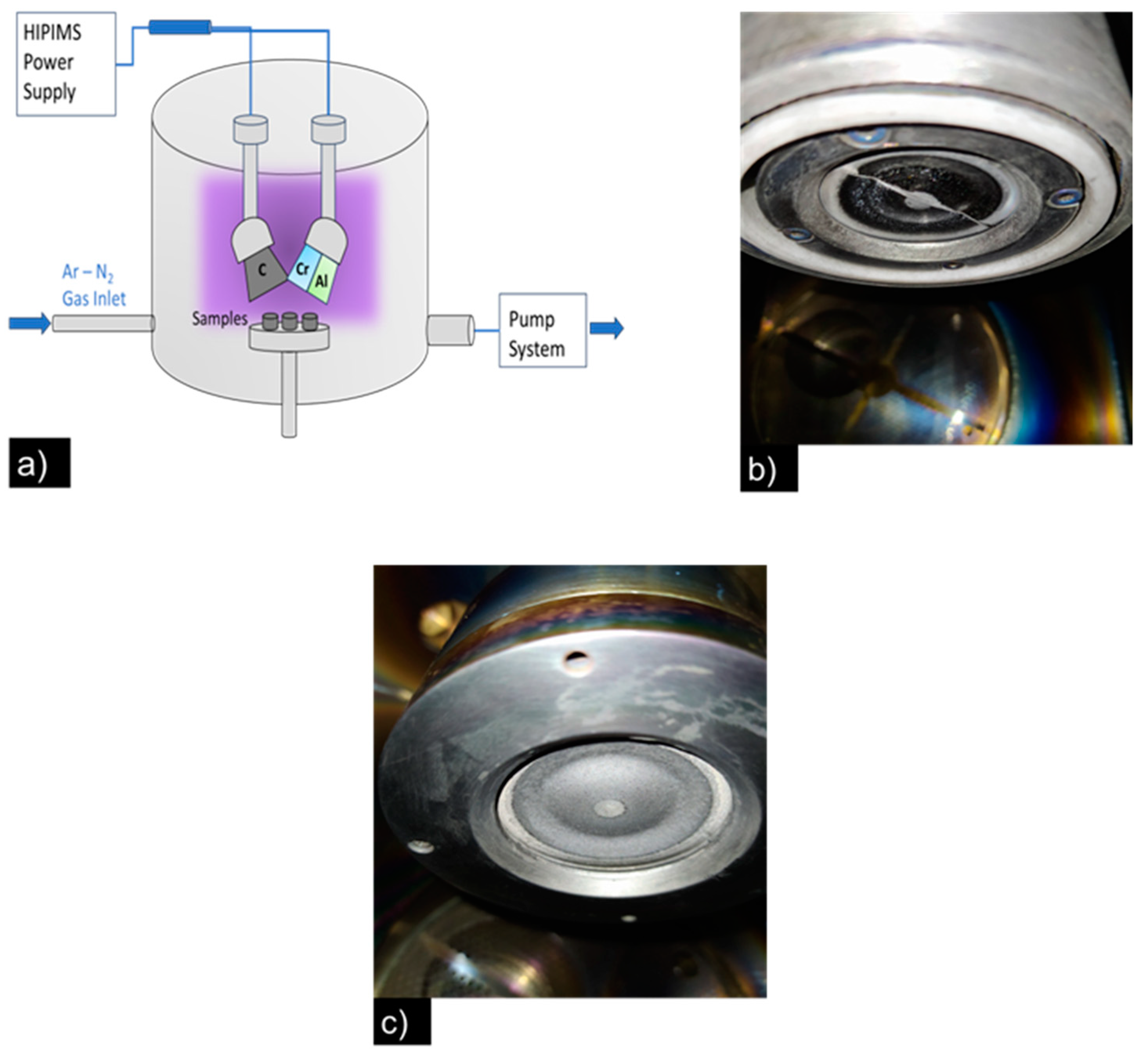
Figure 1. (a) Schematic of the high-power impulse magnetron sputtering system (HIPIMS). (b) Cr-Al target (0.50:0.50) area ratio after the coating process and (c) the C target after the coating process.
Coatings 13 01344 g001
Figure 2. XRD diffractograms: (a) for sample S1 and S2. Raman spectrum: (b) CNx top layer.
Coatings 13 01344 g002
Figure 3. SEM cross-section micrographics: (a) sample S1 and (b) sample S2.
Coatings 13 01344 g003
Figure 4. Load-displacement graphic test: (a) S1 sample and (b) S2 sample. Progressive load scratch test data and SEM image: (c) S1 sample and (d) S2 sample.
Coatings 13 01344 g004
Figure 5. (a) Coefficient of friction as a function of different normal loads for samples S1 and S2. (b) Width wear track as a function of different normal loads. (c) Wear volume as function of normal loads. (d) Variation of coefficient of friction at a 40 N normal load. (e) Variation of coefficient of friction at a 60 N normal load. (f) Variation of coefficient of friction at a 80 N normal load.
Coatings 13 01344 g005
Figure 6. Wear tracks from sample S1 under the fretting test with different loads: (a) 40 N, (b) ampliation, (c) 60 N, (d) ampliation, (e) 80 N, and (f) ampliation.
Coatings 13 01344 g006
Figure 7. Wear tracks from sample S2 under fretting test with different loads: (a) 40 N, (b) ampliation, (c) 60 N, (d) ampliation, (e) 80 N, and (f) ampliation.
Coatings 13 01344 g007
Figure 8. Raman analysis after the fretting wear test in sample S1: (a) wear track in the test at 40 N, (b) counter face track, (c) wear track in the test at 60 N, (d) counter face track, (e) wear track in the test at 80 N, (f) counter face track.
Coatings 13 01344 g008
Figure 9. Raman analysis after the fretting wear test in sample S2: (a) wear track in the test at 40 N, (b) counter face track, (c) wear track in the test at 60 N, (d) counter face track, (e) wear track in the test at 80 N, (f) counter face track.
Coatings 13 01344 g009
Figure 10. Deconvolution of Raman spectra of the CNx top layer film deposited for sample S2 and worn surface during the fretting test at normal loads of 40 N (40NC4) and 60 N (60NC2).
Coatings 13 01344 g010
Figure 11. (a) Schematic of a fretting loop. (b) Illustration of fretting conditions. Fretting loop shape: (c) partial slip regime and (d) gross slip regime.
Coatings 13 01344 g011
Figure 12. Friction force vs. displacement loops obtained at periodic intervals during the fretting test for sample S1, conducted at different loads: (a) 40 N, (b) 60 N, and (c) 80 N.
Coatings 13 01344 g012
Figure 13. Friction force vs. displacement loops obtained at periodic intervals during the fretting test for sample S2, conducted at different loads: (a) 40 N, (b) 60 N, and (c) 80 N.
Coatings 13 01344 g013
Table 1. Architecture and deposition parameters of multilayers.
Sample IDLayerPulse
Width (µs)
Frequency
(Hz)
Voltage
(V)
Peak Current (A)Thickness/Period (nm)Time (min)
PeriodsComposition
S14CrAl2030061034155 ± 4.012
4CrAlN2030042050235 ± 5.845
S23CrAl2030061034155 ± 4.012
3CrAlN2030042050235 ± 5.845
1 top layerCNx303007355385 ± 3.113
Table 2. XRF atomic composition of multilayer samples S1 and S2.
Sample ID:Atomic Composition (at.%)
CrAlN
S132.4666.30-
S227.5269.74-
Table 3. Mechanical properties of CrAL/CrAlN and CrAl/CrAlN/CNx multilayers.
Sample ID:Thickness (µm)Ra (µm)H (GPa)E (GPa)ErH/EH3/E2H/ErER (%)
S11.5 ± 0.060.03628 ± 0.005823.08 ± 2.8508 ± 39.33730.0450.0470.061736.24
S21.2 ± 0.050.02636 ± 0.005520.58 ± 1.8397 ± 33.63050.0510.0550.067445.75
Table 4. Friction coefficient, critical load, critical stress, and adhesion energy obtained by nano scratch tests.
Sample ID:vµLc1 (N)Lc2 (N)σc (GPa)Gc (J/m2)
S10.220.0860.7290.8590.53390.5329
S20.190.0560.4340.6650.37550.2539
Table 5. Dissipated energy (J/m), calculated from fretting tests at different normal loads.
Sample ID:Normal Load
40 N60 N80 N
S10.856 × 10−3 ± 1.21 × 10−50.705 × 10−3 ± 1.90 × 10−50.932 × 10−3 ± 1.06 × 10⁻⁵
S20.699 × 10−3 ± 0.70 × 10⁻⁵ 0.633 × 10⁻³ ± 0.65 × 10−50.890 × 10−3 ± 1.04 × 10⁻⁵
Disclaimer/Publisher’s Note: The statements, opinions and data contained in all publications are solely those of the individual author(s) and contributor(s) and not of MDPI and/or the editor(s). MDPI and/or the editor(s) disclaim responsibility for any injury to people or property resulting from any ideas, methods, instructions or products referred to in the content.