Article

Optimization of Crystalline Diamond Coating Structure Architecture for Improving Adhesion and Cutting Performance in Milling with Cemented Carbide Inserts

by
Georgios Skordaris
1,*,
Konstantinos-Dionysios Bouzakis
1,
Antonios Bouzakis
2,
Dimitrios Tsakalidis
1,
Apostolos Boumpakis
1,
Spyridon Kompogiannis
1,
Emmanouil Bouzakis
3,
Oliver Lemmer
4,
Werner Kölker
4 and
Michael Woda
4
1
Laboratory for Machine Tools and Manufacturing Engineering, Mechanical Engineering Department, Aristotle University of Thessaloniki, 54124 Thessaloniki, Greece
2
Impact-BZ, London SW11 5QL, UK
3
Department of Mechanical Engineering, University of Thessaly, 38334 Volos, Greece
4
CemeCon AG, 52146 Würselen, Germany
*
Author to whom correspondence should be addressed.
Coatings 2023, 13(7), 1170; https://doi.org/10.3390/coatings13071170
Submission received: 25 May 2023 / Revised: 19 June 2023 / Accepted: 22 June 2023 / Published: 28 June 2023
(This article belongs to the Special Issue New Cutting Techniques for Improved Machining)

Abstract

:
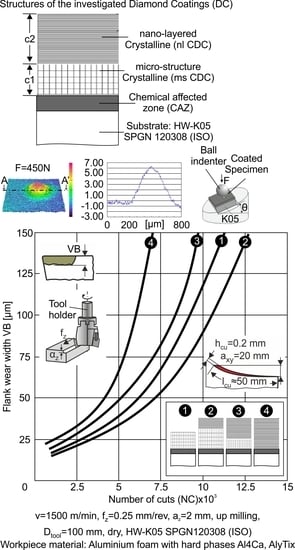
The adhesion, structure architecture, and residual stresses of crystalline diamond coatings (CDCs) on cemented carbide inserts are the factors that significantly affect tool life. The influence of these factors on cutting performance cannot be investigated separately since interactions among them exist. The paper elucidates such dependencies to optimize the CDC architecture and improve cutting performance. In this context, diamond coatings possessing different architectures were deposited on cemented carbide tools. The fatigue endurance and the milling performance of the coated tools were investigated using impact and milling tests, respectively. The residual stresses in the film structures were determined through impact tests and appropriate (Finite Element Analysis) FEA evaluation of the corresponding results. According to the obtained results, the application of a bottom micro-structured CDC prior to the deposition of an upper nanolayered one with inferior thickness improves the coated tools’ cutting performance. An optimum coating architecture is associated with a thickness ratio between the micro-structured bonding to the upper nanolayered CDCs of 2/1. Hereupon, the augmentation of coated tool life via the application of an optimum diamond coating architecture compensates for the high tool cost and improves milling productivity. The latter is further enhanced as the number of tool replacements decreases.

Graphical Abstract

1. Introduction

Crystalline diamond coatings (CDCs) on cemented carbide inserts are widely used in various cutting applications, especially for aluminum alloys, carbon-fiber-reinforced composite materials, etc. [1,2,3,4,5]. Such coatings are characterized by high compressive residual stresses in their structures, significantly affecting the interfacial fatigue strength [6,7]. The fatigue strength of the diamond coating–substrate interface is a key issue for the coated tool life, especially when the coated tools are used in machining processes with interrupted chips, thus characterized by the highly developed dynamic loads [7,8,9]. As a consequence of the applied dynamic loads developed in the coating–substrate interface during cutting, a wear mechanism relevant to coating detachment and, thus, bulge formation appears in the case that the interfacial toughness of the diamond film is insufficient. The lifting of the diamond coating from its substrate can be explained by the release of the compressive residual stresses from its structure after interface damage [10]. In order to improve the interfacial fatigue strength and, thus, film adhesion, various procedures have been proposed with the aim of reinforcing the bonding between the diamond coating and its cemented carbide substrate. Selective chemical co-etching conducted on hardmetal tools to superficially delete non-adhesive cobalt is highly recommended in the literature [1,10,11,12]. Moreover, the application of interlayer materials has also been proposed as another solution for improving the adhesion and nucleation densities of diamond coatings on various substrates [13,14]. Another crucial issue for the cutting performance of diamond-coated tools is the architecture of the deposited films. Related investigations have been conducted by other researchers in order to examine the influence of different structures, such as of micro-crystalline, nano-crystalline, and micro/nano-crystalline composite of diamond coatings on their tribological behavior and on the chemical bond to the substrate as well as on their milling performance [4,15].
Considering the above-mentioned facts, the adhesion, structure architecture, and residual stresses of such coatings are the main factors dominantly affecting cutting performance. Due to the underlying interactions among those factors, their influence on cutting performance cannot be investigated individually. For example, nanolayer crystalline diamond coatings improve manufacturing accuracy due to their smooth surface and decelerate crack propagation. However, they possess higher residual stresses compared to micro-coating structures. The latter fact can deteriorate coating–substrate adhesion and herewith diminish cutting performance. The present paper elucidates such dependencies to facilitate the optimization of the coating architecture to enhance cutting performance when using CD-coated cemented carbide inserts.

2. Materials and Methods

The used cemented carbide K05 inserts were chemically treated with optimized process parameters to decrease the superficial Co content to improve coating adhesion. Since residual stresses develop in a CDC mainly due to epitaxial crystal differences and thermal expansion coefficient mismatch in the CDC and its cemented carbide substrate, micro-fractures may occur in the coating–substrate interface [10,16,17]. To avoid such failures, micro-structured (ms) CDCs are usually used as bonding layers, which can more effectively absorb residual stresses. In addition, since nanolayered (nl) CDCs possess low surface roughness and decelerate crack propagation down to the substrate, they are promising in terms of increasing manufacturing accuracy and tool life [15].
Considering these facts, to determine an optimum coating microarchitecture, four cemented carbide insert batches were formed. The first one was coated with a micro-structured crystalline diamond coating (ms CDC) of 5 μm thickness via the hot filament method using a CC800/9Dia CEMECON coating machine (see Figure 1). Two further insert batches, the 2nd and 3rd ones, were manufactured with two layers. The bonding layer was an ms CDC and the upper one was a nanolayered (nl CDC), with thicknesses 6 μm and 3 μm for the 2nd batch and 3 μm and 6 μm for the 3rd, respectively (see Figure 1). The upper layered coating consists of individual nano sub-layers alternating with micro-sized ones that are a few nm in thickness. The overall thickness of the coating was held constant, equal to 9 μm. The last 4th insert batch was coated only with an nl CDC of 9 μm thickness. During the coating CVD deposition, the substrate temperature was adjusted to 900 °C. The filament temperature amounted to approximately 2000 °C, and the total pressure amounted to 30 mbar. At a carbon-to-hydrogen ratio of 1% and a gas flow of 2 L/min, the coating growth rate was around 0.5 mm/h. These conditions were also adjusted in order to attain improved coating crystallinity [7].
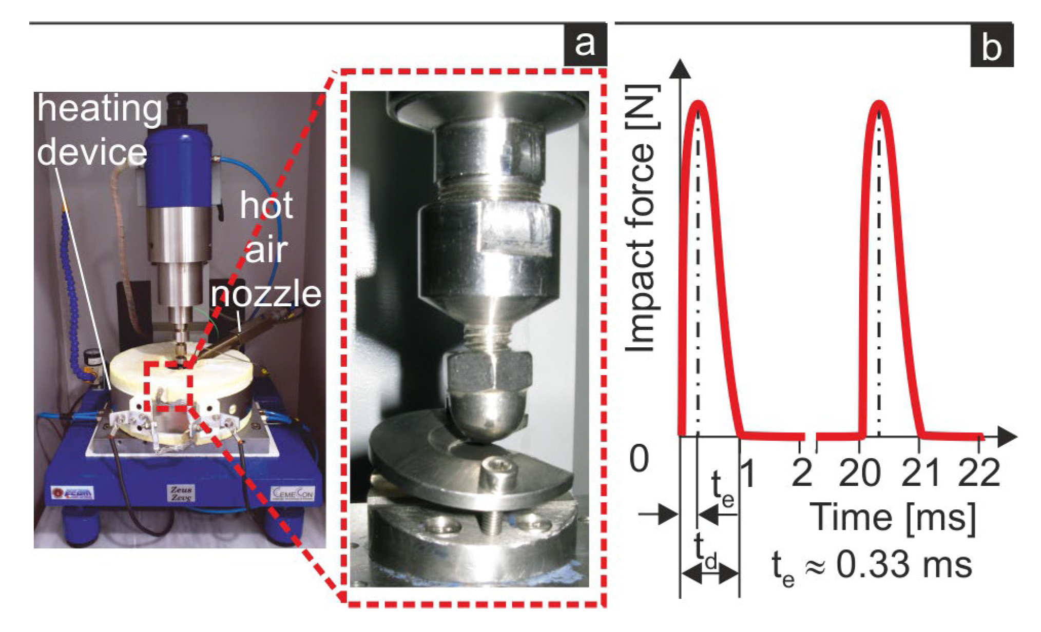
To check the adhesion and the magnitude of the developed residual stresses of the prepared CDCs with the described structures, an inclined impact test under various loads and a temperature of 300 °C was used. The latter temperature was chosen since it is approximately equal to the temperatures reached during milling aluminum alloys with CDC-coated tools [8]. The employed impact test device used was the Apollo NXG of Impact Bz Ltd (Thessaloniki, Greece). [18] (see Figure 2a). In Figure 2b, the applied force signal during the impact test is shown.
The developed impact imprints were evaluated through 3D measurements using the confocal microscope, mSURF, of NANOFOCUS AG. Moreover, appropriately developed FEA models were employed to calculate the structural and thermal stresses of the examined diamond coating cases, as shown in Figure 3 [10]. More specifically, by using the axisymmetric FEA model shown in Figure 3a, the magnitude of thermal stresses in the diamond coating structure developed during cooling from the deposition temperature to the operational one can be calculated. The thermal-dependent expansion coefficients of the diamond coating and its substrate were considered. The overall amount of compressive residual stresses can be estimated using the FEA model presented in Figure 3b. The latter model simulates the film lifting after interfacial fatigue failure that results in the release of residual stresses. Necessary data, such as the diameter of the detached film and the height of the film bulges in the employed FEA model, were experimentally detected using the impact test results. The milling investigations were performed by employing a three-axis numerically controlled milling center using aluminum foam as the workpiece material. This workpiece material consists of various hard phases, such as Al4Ca and AlyTix, as related optical microscopy observations using standard metallographic techniques revealed (see Figure 4). The structure of the workpiece material results in the development of intense dynamic loads on the cutting edge of the coated tools during milling [19].

3. Results

3.1. Impact Performance of the Examined Diamond Coatings

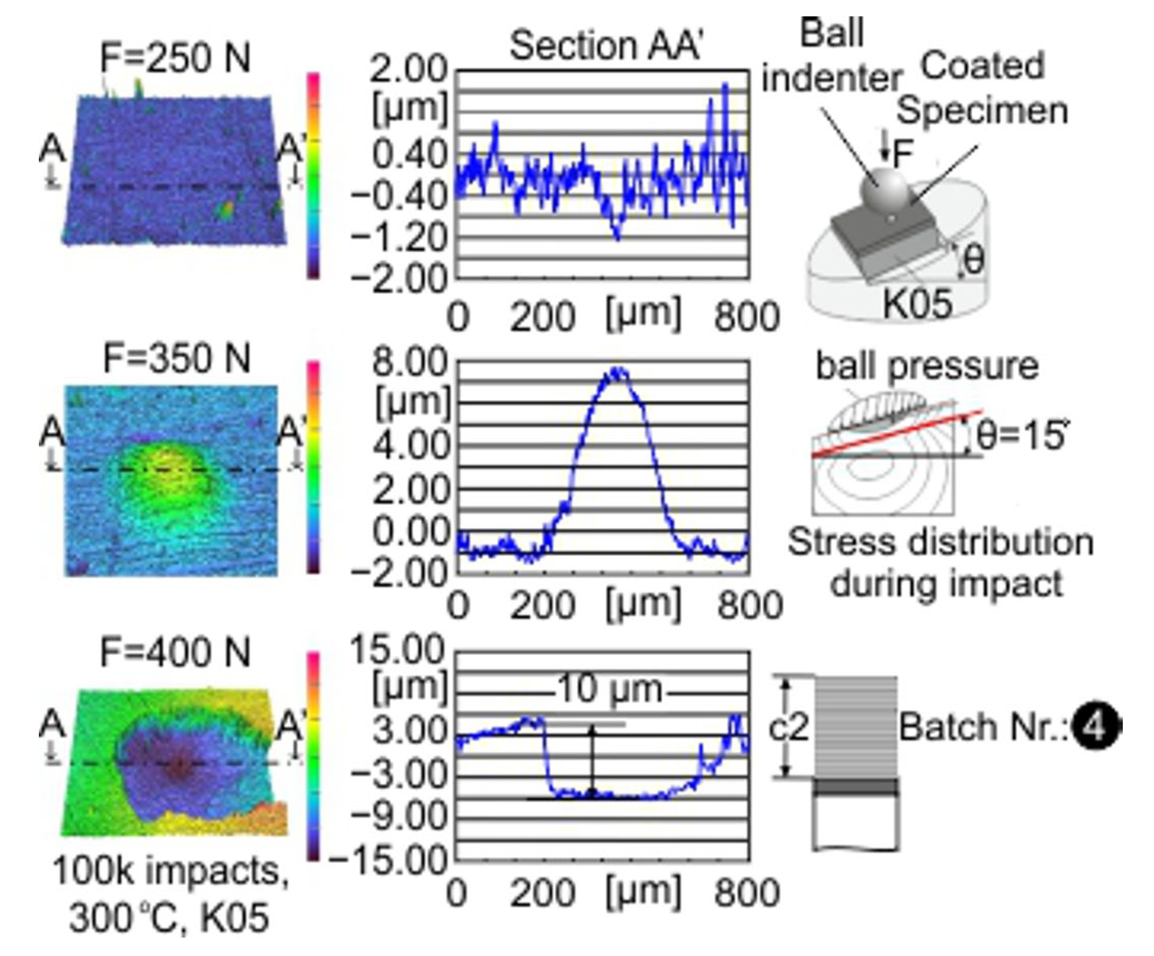
Inclined impact tests were conducted on the examined diamond-coated inserts at a temperature of 300 °C for 100,000 impacts and under different loads to characterize the adhesion quality and detect residual stresses. Characteristic results of such tests in the case of the 4th insert batch coated only with an nl CD film are presented in Figure 5. Based on the developed imprint geometry under various loads, the critical impact force inducing the onset of coating detachment due to interface fatigue after 100,000 impacts can be detected, as in the following described. In the present case, under impact forces greater than 250 N, coating delamination may occur due to coating–substrate interface fatigue failure and coating compressive residual stresses release, leading to bulge formation. As can be seen in Figure 5, under an impact force of 350 N, a bulge of about 8 μm formed. The height and base diameters of this bulge further increase with the increasing number of impacts up to a critical size at which it fails due to fatigue induced by the repetitive mechanical loads [10]. Under impact loads greater than 400 N, the formed bulges are damaged at fewer than 100,000 impacts.
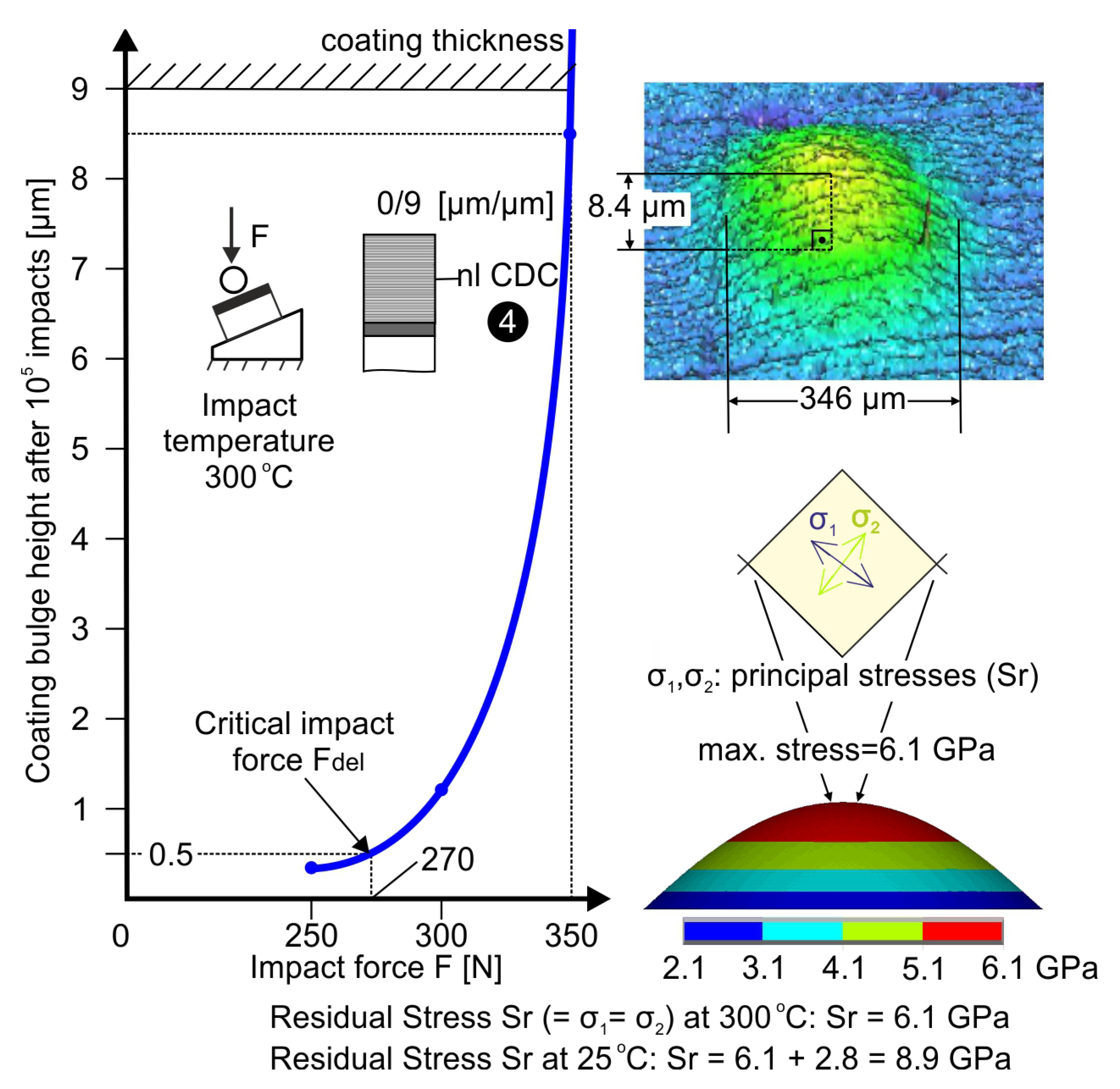
Considering the previous results, the bulge height versus the impact force can be plotted, as shown in the left part of Figure 6. Introducing a bulge height of 0.5 μm as a criterion for the onset of coating delamination, the corresponding critical impact force Fdel can be graphically determined. In the case of the only-nl CD-coated insert, Fdel amounts to approximately 270 N (see Figure 6). The latter force is temperature-dependent [8]. Furthermore, employing the FEA models shown in Figure 3, which are associated with the mathematical procedure described in [10], and taking into account the bulge dimensions, the released coating compressive residual stresses that led to the demonstrated bulge formation at 300 °C were predicted. In the exhibited nl CDC case, these are roughly equal to 6.1 GPa, as shown in Figure 6. The overall residual stresses in the diamond coating structure at 25 °C were calculated considering the increase in thermal stresses due to temperature reduction, as illustrated in Figure 6 and explained in [8]. Herein, the occurring compressive thermal residual stresses from 300 °C to 25 °C are overlaid with the existing structural and thermal ones at 300 °C.
Related investigations were conducted in the case of the 1st insert batch only coated with a micro-structured crystalline diamond coating (ms CDC) of 5 μm thickness. According to the inclined impacts tests after 105 impacts shown in Figure 7a, no damage to the coating surface appears at a load of 350 N. At a further load increase at 450 N, an interfacial fatigue failure occurs, the high compressive residual stresses of the micro-structured diamond coating are released, and the detached coating hikes up at a certain maximum height (bulge formation). The critical impact force Fdel amounts to approximately 400 N for attaining a bulge height equal to 0.5 μm after the coating detachment (see Figure 7b). Finally, the compressive residual stresses in the film structure at 300 °C and at 25 °C were calculated via the methodologies described in [10] and are presented in Figure 7b. As it can be observed, the magnitude of the compressive residual stresses in the case of a micro-structured film is lower compared to the related ones of a nano-layered crystalline coating.
Inclined impact tests at 300 °C were also conducted on the two further insert batches, the 2nd and 3rd ones. As already described, these coatings have two layers. The bonding layer consists of an ms CDC and the upper one, a nanolayered (nl CDC) with thicknesses 6 μm and 3 μm for the 2nd batch and 3 μm and 6 μm for the 3rd. Applying the afore-described experimental-analytical methods, the critical impact force Fdel for the coating delamination at 300 °C and the coating residual stresses at 25 °C were also determined. An overview of the obtained results for all investigated CD-coated cemented carbide insert batches 1 to 4 is demonstrated in Figure 8. Each of the exhibited values represents the mean of one of three impact tests. The maximum results’ deviation from each time mean value was, in all cases, less than 5%. The maximum standard deviation Smax of the applied critical forces in all investigated cases is less than 8.

3.2. Milling Performance of the Examined Diamond Coatings

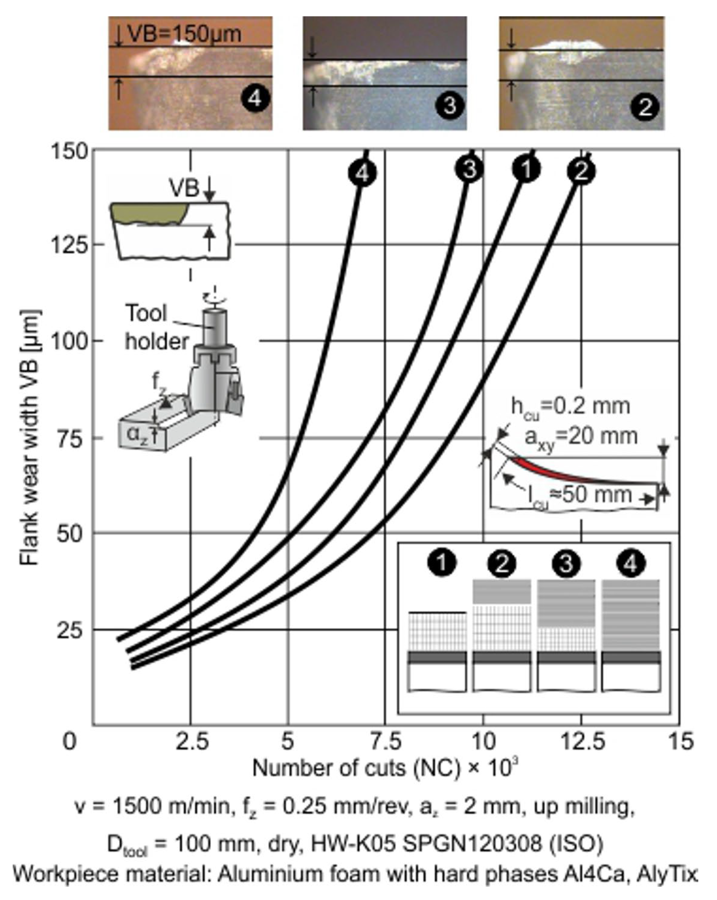
Milling experiments were conducted to investigate the wear resistance of the examined coating structures against the developed dynamics loads. The cutting temperature was calculated to be approximately 300 °C during one milling revolution [8]. In the results illustrated in Figure 9, the maximum temperature in the cutting-edge transient region was estimated to be between 250 and 300 °C due to the interrupted cutting procedure. Herein, it was assumed that the CDC coating, as well as the substrate properties, remain practically constant in this temperature range [20]. The flank wear development versus the number of cuts in all of the investigated CDC structure cases is shown in Figure 9. As expected, when employing a micro-structured CDC as a bonding layer (1st, 2nd, and 3rd insert batches), flank wear land development is less intensive in comparison to the coated inserts of the 4th batch with a nanolayered CDC of 9 μm thickness. It must be pointed out that the coated inserts of the 2nd batch with a micro-structured bonding layer of 6 μm and a 3 μm nano upper layered region represent an optimum coating architecture combining the advantages of both low surface roughness and residual stresses associated with sufficient adhesion.

4. Discussion

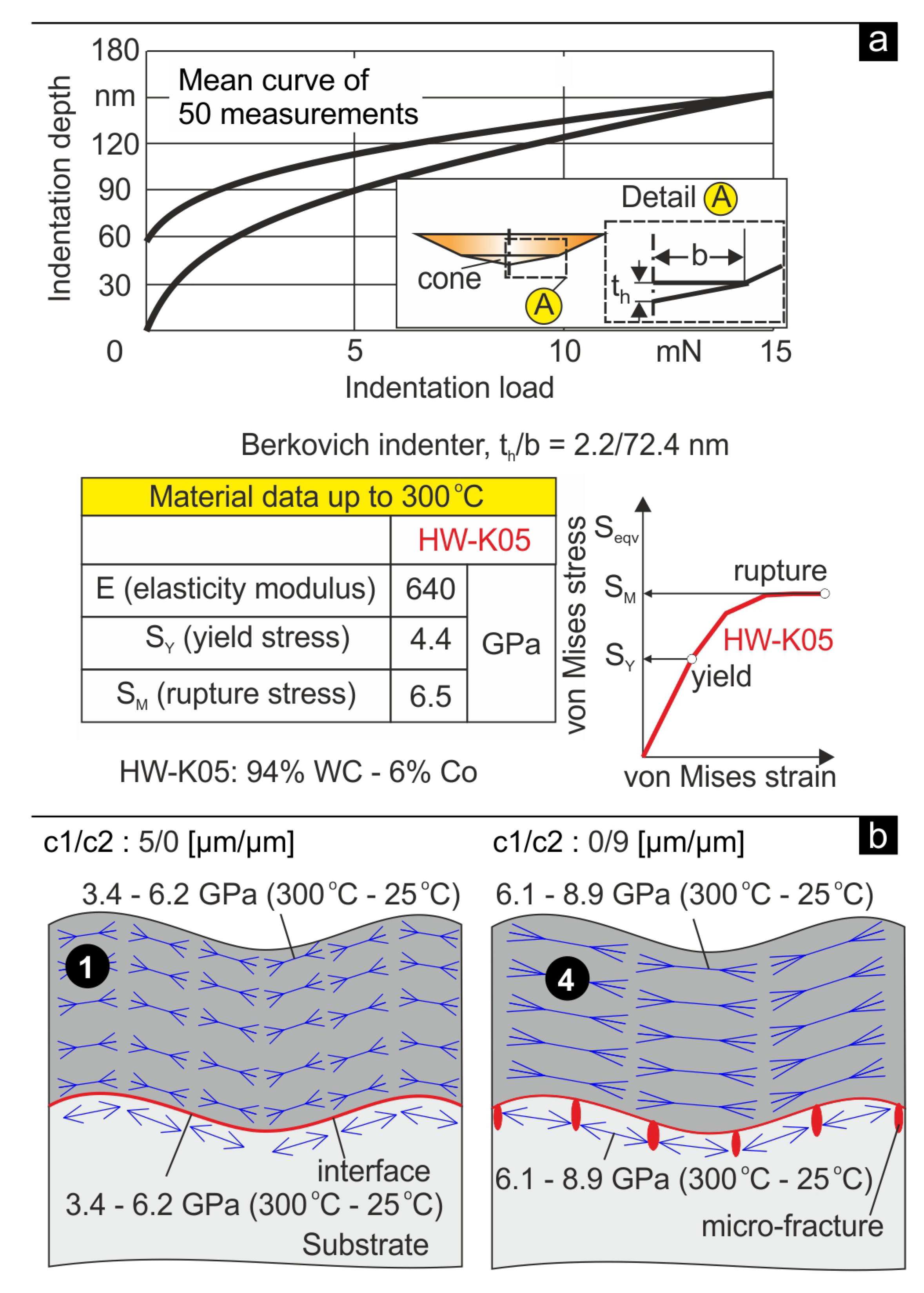
To explain the wear behavior in the milling of diamond coatings with different structures, the following issues must be considered. The nanolayered coatings or even the nanolayered ones with a comparably thin bonding micro-CDC (4th and 3rd insert batches, respectively) possess high levels of residual stresses compared to the coated inserts with a micro-CDC or additionally with a thinner upper nanolayer (1st and 2nd insert batches). Residual stresses in CD films could enhance the coating adhesion since they contribute to roughness’s locking in the coating–substrate interface. However, they may overstress the substrate material and lead to micro-fractures in the interface region, thus deteriorating the coating adhesion. Recent investigations revealed that low film adhesion is associated with insufficient fatigue strength of the diamond coating–substrate interface, which leads to rapid film delamination and substrate revelation in milling [1,8]. The interface fatigue strength of diamond coatings is a prevailing factor for attaining a sufficient tool life in milling. During milling, due to the interrupted material removal, the cutting edges are subjected to repetitive impulsive loads. The effect of the milling process dynamic on the wear evolution was extensively investigated [19,21]. In this way, the fatigue strength of the coating–substrate interface significantly affects the diamond-coated tool life, whereas dynamic loads are developed in the coating–substrate interface. The nanoindentation curve of K05 inserts with a maximum load of 15 mN is shown in Figure 10a. This curve represents the mean value of 50 measurements. Through the appropriate evaluation of the nanoindentation results using the “SSCUBONI” algorithm [10], the stress–strain curve of the employed K05 inserts as well as characteristic mechanical properties, are shown. These properties are kept constant up to a temperature of 400 °C [20]. Considering the results in Figure 8 and the fact that during one milling revolution, the developed temperatures in the coated tool cutting-edge fluctuate between 25 and 300 °C, the mean residual stresses exceed the substrate rupture stress in the 4th insert batch, micro-fractures in the film-substrate interface develop, and the critical delamination forces diminish (see Figure 10b). Thus, the substrate material deforms without resistance. Consequently, on the one hand, in the case of nanolayered or mainly nanolayered CDCs (4th and 3rd insert batch, respectively), micro-fractures may appear in the coating interface, deteriorating the adhesion and potentially the cutting performance. On the other hand, the existing lower stresses in the micro-CDC (1st batch) as well as in the 2nd batch with a thin upper nanolayered CDC facilitate the roughness locking in the coating interface region without material failures. In this way, the coating adhesion is improved, and a better cutting performance, comparable to insert batches 3 and 4, is expected. Finally, these milling results ascertain the practical experience that micro-structured CDCs enhance the adhesion and, moreover, that the layered film structures decelerate crack propagation and might improve the coated tool’s cutting performance. Herein, the layered upper structure thickness must be restricted to avoid micro-fractures in the coating interface due to high residual stresses.

5. Conclusions

In the paper, the effect of the adhesion, structure architecture, and residual stresses of crystalline diamond coatings (CDCs) deposited on cemented carbide inserts on cutting performance was investigated. In this context, cemented carbide inserts were coated with diamond coatings possessing different architectures. According to the presented investigations, the application of a bottom micro-structured CDC prior to the deposition of an upper nanolayered one with inferior thickness improves the cutting performance of the coated tools. An optimum coating architecture concerning the thickness between the micro-structured bonding to the upper nanolayered CDCs could be a ratio of 2/1. Due to the fact that the micro-CDC structure can more effectively absorb the residual stresses and the layered one decelerates crack propagation, the optimization of the fine architecture of the layered upper CDC consisting of individual nano sub-layers alternating with micro-ones could be an issue of practical significance.

Author Contributions

Conceptualization, G.S., K.-D.B., O.L., W.K. and M.W.; methodology, G.S. and K.-D.B.; software, A.B. (Antonios Bouzakis); validation, D.T., A.B. (Apostolos Boumpakis) and S.K.; formal analysis, G.S. and A.B. (Antonios Bouzakis); investigation, G.S., K.-D.B., A.B. (Antonios Bouzakis), D.T., A.B. (Apostolos Boumpakis), S.K., E.B., O.L., W.K. and M.W.; resources, O.L., W.K., and M.W.; data curation, G.S. and A.B.; writing, original draft preparation, G.S., K.-D.B., A.B. (Antonios Bouzakis) and E.B.; writing, review and editing, G.S., K.-D.B., A.B. (Antonios Bouzakis) and E.B. All authors have read and agreed to the published version of the manuscript.

Funding

This research received no external funding.

Institutional Review Board Statement

Not applicable.

Informed Consent Statement

Not applicable.

Data Availability Statement

Not applicable.

Conflicts of Interest

The authors declare no conflict of interest.

References

  1. Haubner, R.; Kalss, W. Diamond Deposition on Hardmetal Substrates—Comparison of Substrate pretreatments and Industrial Applications. Int. J. Refract. Met. Hard Mater. 2010, 28, 475–483. [Google Scholar] [CrossRef]
  2. Uhlmann, E.; Reimers, W.; Byrne, F.; Klaus, M. Analysis of tool wear and residual stress of CVD diamond coated cemented carbide tools in the machining of aluminum silicon alloys. Prod. Eng. 2010, 4, 203–209. [Google Scholar] [CrossRef]
  3. Skordaris, G.; Kotsanis, T.; Boumpakis, A.; Stergioudi, F. Improvement of the Interfacial Fatigue Strength and Milling Behavior of Diamond Coated Tools via Appropriate Annealing. Coatings 2020, 10, 821. [Google Scholar] [CrossRef]
  4. Wang, H.; Yang, J.; Sun, F. Cutting performances of MCD, SMCD, NCD and MCD/NCD coated tools in high-speed milling of hot bending graphite molds. J. Mater. Process. Technol. 2020, 276, 116401. [Google Scholar] [CrossRef]
  5. Sousa, V.F.C.; Silva, F.J.G. Recent Advances on Coated Milling Tool Technology—A Comprehensive Review. Coatings 2020, 10, 235. [Google Scholar] [CrossRef] [Green Version]
  6. Lee, D.-G.; Fitz-Gerald, J.M.; Singh, R.K. Novel Method for Adherent Diamond Coatings on Cemented Carbide Substrates. Surf. Coat. Technol. 1998, 100–101, 187–191. [Google Scholar] [CrossRef]
  7. Skordaris, G.; Bouzakis, K.-D.; Charalampous, P.; Kotsanis, T.; Bouzakis, E.; Lemmer, O. Effect of structure and residual stresses of diamond coated cemented carbide tools on the film adhesion and developed wear mechanisms in milling. CIRP Ann. Manuf. Technol. 2016, 65, 101–104. [Google Scholar] [CrossRef]
  8. Bouzakis, K.-D.; Skordaris, G.; Bouzakis, E.; Charalampous, P.; Kotsanis, T.; Tasoulas, D.; Kombogiannis, S.; Lemmer, O. Effect of the interface fatigue strength of NCD coated hard metal inserts on their cutting performance in milling. Diam. Relat. Mater. 2015, 59, 80–89. [Google Scholar] [CrossRef]
  9. Wu, T.; Cheng, K. Micro milling performance assessment of diamond-like carbon coatings on a micro-end mill. Proc. Inst. Mech. Eng. Part J J. Eng. Tribol. 2013, 227, 1038–1046. [Google Scholar] [CrossRef] [Green Version]
  10. Bouzakis, K.-D.; Skordaris, G.; Bouzakis, E.; Makrimallakis, S.; Kombogiannis, S.; Lemmer, O. Fatigue strength of diamond coatings’ interface assessed by inclined impact test. Surf. Coat. Technol. 2013, 237, 135–141. [Google Scholar] [CrossRef]
  11. Fan, S.; Kuang, T.; Xu, W.; Zhang, Y.; Su, Y.; Lin, S.; Wang, D.; Yang, H.; Zhou, K.; Dai, M.; et al. Effect of pretreatment strategy on the microstructure, mechanical properties and cutting performance of diamond coated hardmetal tools using HFCVD method. Int. J. Refract. Met. Hard Mater. 2021, 101, 105687. [Google Scholar] [CrossRef]
  12. Rugóczky, P.; Muránszky, G.; Lakatos, J. Comparative investigations of the selective Co etching from hardmetal support layer of diamond coating. IOP Conf. Ser. Mater. Sci. Eng. 2019, 613, 012015. [Google Scholar] [CrossRef]
  13. Polini, R.; Kumashiro, S.; Jackson, M.J.; Amar, M.; Ahmed, W.; Sein, H. A study of diamond synthesis by hot filament chemical vapor deposition on Nc coatings. J. Mater. Eng. Perform. 2005, 15, 218–222. [Google Scholar] [CrossRef]
  14. Silva, S.; Mammana, V.P.; Salvadori, M.C.; Monteiro, O.R.; Brown, I.G. WC–Co cutting tool inserts with diamond coatings. Diam. Relat. Mater. 1999, 8, 1913–1918. [Google Scholar] [CrossRef]
  15. Wang, C.; Wang, X.; Sun, F. Tribological behavior and cutting performance of monolayer, bilayer and multilayer diamond coated milling tools in machining of zirconia ceramics. Surf. Coat. Technol. 2018, 353, 49–57. [Google Scholar] [CrossRef]
  16. Woehrl, N.; Hirte, T.; Posth, O.; Buck, V. Investigation of the Coefficient of Thermal Expansion in Nanocrystalline Diamond Films. Diam. Relat. Mater. 2009, 18, 224–228. [Google Scholar] [CrossRef]
  17. Slack Glen, A.; Bartram, S.F. Thermal Expansion of Some Diamond-like Crystals. J. Appl. Phys. 1975, 46, 89–98. [Google Scholar] [CrossRef]
  18. Impact-BZ Ltd. Available online: www.impact-bz.com (accessed on 11 January 2023).
  19. Cheng, K. (Ed.) Machining Dynamics: Theory, Applications and Practices; Springer: London, UK, 2008. [Google Scholar]
  20. Teppernegg, T.; Klünsner, T.; Kremsner, C.; Tritremmel, C.; Czettl, C.; Puchegger, S.; Marsoner, S.; Pippan, R.; Ebner, R. High temperature mechanical properties of WC–Co hard metals. Int. J. Refract. Met. Hard Mater. 2016, 56, 139–144. [Google Scholar] [CrossRef]
  21. Bouzakis, K.D.; Makrimallakis, S.; Skordaris, G.; Bouzakis, E.; Kombogiannis, S.; Katirtzoglou, G.; Maliaris, G. Coated tools’ performance in up and down milling stainless steel, explained by film mechanical and fatigue properties. Wear 2013, 303, 546–559. [Google Scholar] [CrossRef]
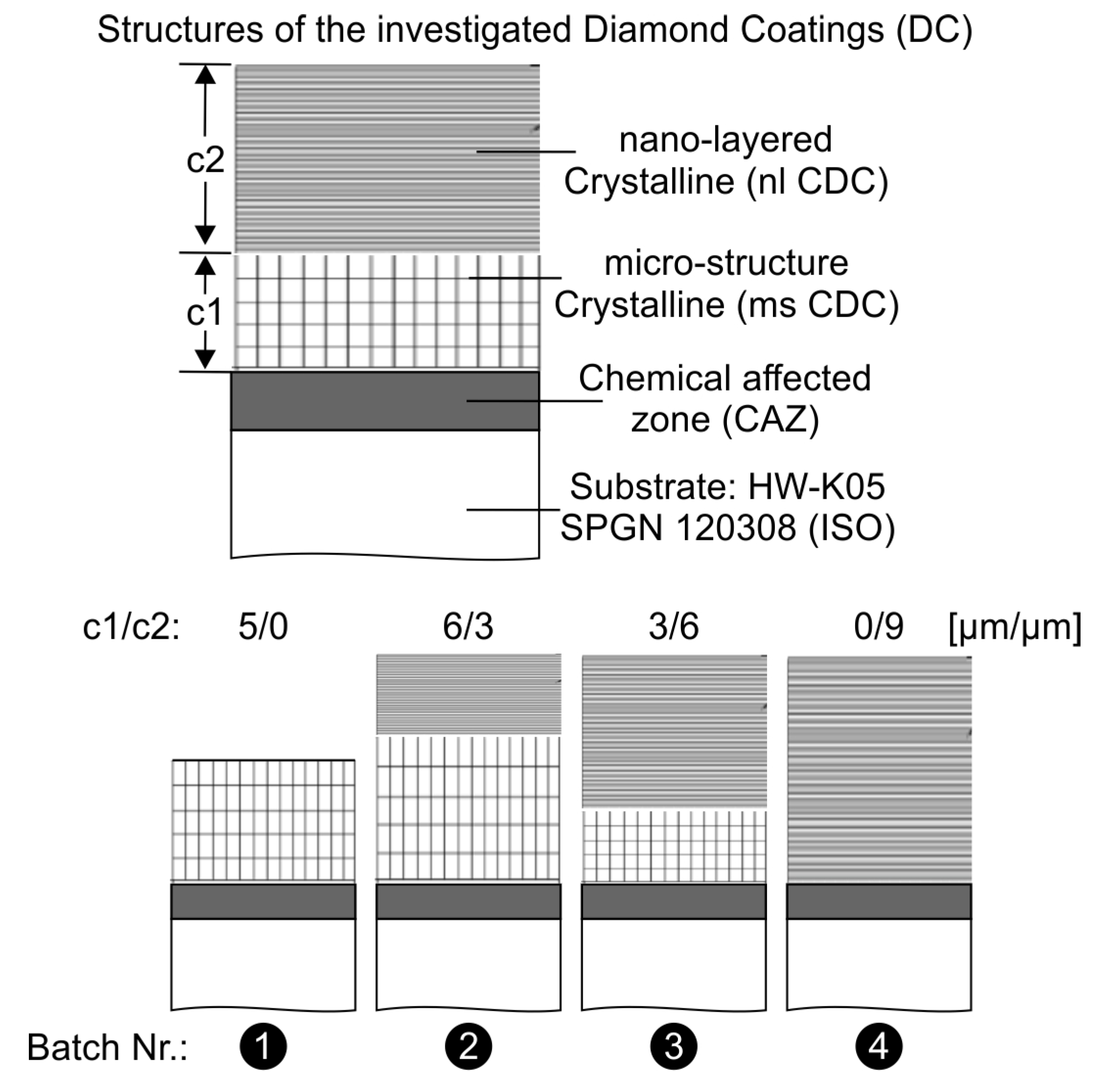
Figure 1. The employed cemented carbide insert batches with various coating architectures.
Coatings 13 01170 g001
Figure 2. (a) The device used to conduct inclined impact tests; (b) the applied force signals.
Coatings 13 01170 g002
Figure 3. (a) The developed FE model used to calculate thermal residual stresses after the film cooled from the deposition temperature to operational one; (b) the developed FE model used to simulate the coating bulge geometry.
Coatings 13 01170 g003
Figure 4. Characteristic micro-graphs of the aluminum foam used in milling experiments.
Coatings 13 01170 g004
Figure 5. Formation of a coating bulge due to interface fatigue failure during the inclined impact test in the examined case of the 4th batch.
Coatings 13 01170 g005
Figure 6. Determination of critical force Fdel for coating delamination and coating residual stresses considering the bulge dimensions formed during the inclined impact test.
Coatings 13 01170 g006
Figure 7. (a) Formation of a coating bulge due to interface fatigue failure during the inclined impact test in the examined 1st batch case; (b) calculation of the overall residual stresses in the film structure at 300 °C and 25 °C.
Coatings 13 01170 g007
Figure 8. The determined data for the investigated CDCs with various structure architectures.
Coatings 13 01170 g008
Figure 9. Flank wear width VB over the number of cuts in milling for the investigated CDCs with various structure architectures.
Coatings 13 01170 g009
Figure 10. (a) Substrate material mechanical properties; (b) coating interface failure due to exceed of the substrate rupture stress caused by high residual stresses.
Coatings 13 01170 g010
Disclaimer/Publisher’s Note: The statements, opinions and data contained in all publications are solely those of the individual author(s) and contributor(s) and not of MDPI and/or the editor(s). MDPI and/or the editor(s) disclaim responsibility for any injury to people or property resulting from any ideas, methods, instructions or products referred to in the content.