Article

Construction of Amphiphilic Indocyanine–Green–Based Langmuir Film and Drop–Casting Film with Photoelectric Conversion Properties

1
Hebei Key Laboratory of Agroecological Safety, Hebei University of Environmental Engineering, Qinhuangdao 066102, China
2
State Key Laboratory of Metastable Materials Science and Technology, Yanshan University, Qinhuangdao 066004, China
3
School of Information and Electrical Engineering, Hangzhou City University, Hangzhou 310015, China
*
Authors to whom correspondence should be addressed.
Coatings 2023, 13(8), 1423; https://doi.org/10.3390/coatings13081423
Submission received: 29 June 2023 / Revised: 6 August 2023 / Accepted: 10 August 2023 / Published: 14 August 2023
(This article belongs to the Special Issue Innovative Thin Films for Opto/Electronic Devices)

Abstract

:
Molecular self–assembly is the automatic formation of functional assemblies of different structural components through weak, reversible, non–covalent interactions on the basis of molecular recognition. Amphiphilic molecules have a natural advantage in self–assembly at the gas/liquid interface. In this work, two amphiphilic molecules with a special molecular structure, indocyanine green (ICG) and a derivative of indocyanine green (CCS), were combined with two dye molecules (tetraphenylporphyrin tetrasulfonic acid hydrate (TPPS) and nickel (II) phthalocyanine–tetrasulfonic acid tetrasodium salt (TsNiPc) for self–assembly through the Langmuir–Blodgett (LB) technique. The nanostructure and assembly behavior in ordered self–assembled films are effectively regulated by inducing dye molecules to form different types of aggregates (H– and J–aggregates). In addition, we prepared composite films containing the same functional components using the conventional drop–casting technique and performed a series of comparative experiments with LB films. The degree of hydrophilicity was found to be related to roughness, with LB composite films being flatter and denser, with the lowest roughness and the best hydrophobicity compared to drop–casting films. Notably, the LB films showed better optoelectronic properties under the same conditions, providing new clues for the application of optoelectronic functional ultrathin film devices.

1. Introduction

Self–assembly refers to the process through which the component structure of a system changes from simple to complex and from disorder to order without human intervention. Self–assembly technology is widely used in the preparation of functional thin film materials because of its controllable size, composition and morphology. The development of supramolecular self–assembled film materials is very rapid and has gradually led to multilevel, dynamic and controlled self–assembly, which plays an important role in separation and analysis, nanotechnology and biomedicine [1,2,3,4,5]. In particular, ordered ultrathin films play an important role in the ordered supramolecular assembly at the interface.
Specifically, Langmuir–Blodgett (LB) technology provides an effective method to generate highly ordered molecular films [6,7,8]. LB technology can transfer single molecules from the subphase to solid substrate to form uniform films [9,10,11]. In addition to the traditional amphiphilic molecules, many non–amphiphilic functional materials, such as non–long–chain substituted porphyrins, phthalocyanines, conductive polymers and other molecules, are gradually being introduced into LB films [12,13,14]. From the literature, phthalocyanine molecules can form stable monolayers at the gas/liquid interface through electrostatic interactions [15,16,17,18,19,20,21]. For example, Nickel phthalocyanine tetrasodium sulfonate (TsNiPc) molecules are widely used in photoelectric sensing devices, nano–electronic devices and molecular sensors because of their good photoelectric sensing performance. Here, the change in aggregation state directly affects their optoelectronic properties. Tetraphenylporphyrin tetrasulfonic acid hydrate (TPPS) has special dye properties, and it is easier to form different aggregation states with it under the influence of different pH environments. However, the change in aggregation degree of TPPS under different influences will have a direct impact on its photoelectric properties [22]. For example, Wang et al. prepared LB composite films through self–assembly using phthalocyanine dye molecules and the two–dimensional material black phosphorus [23]. The prepared composite LB films had adjustable structure and thickness and exhibited good acid–base gas response, SERS and photocurrent generation properties. Bian et al. successfully prepared an orderly and uniform composite LB film with adjustable structures and thickness based on novel organic small molecules composited with TsNiPc and TPPS subphases. The photoelectric conversion properties of composite films were also investigated. The results demonstrate that films transferred to the surface of substrates in different aggregated morphologies exhibit different photoelectrochemical performance [21].
In this work, after a series of studies on the interface coordination of LB films, we selected two amphiphilic molecules with sulfonic acid groups, indocyanine green (ICG) and a derivative of indocyanine green (CCS) (Figure 1a). A stable monolayer film can be formed at the gas–liquid interface, and then the film can be transferred to various substrates to study the preparation and photoelectric properties of LB films. In addition, the drop–casting process is a much simpler film forming process than other film forming processes. Because of its simplicity, ease of control, low cost and high material utilization, the drop–casting process is widely used in the fields of optoelectronics, biomedicine and energy. Therefore, we have taken the different aggregation forms of dyes as a starting point and further compared the differences of film materials formed using the two methods.

2. Experimental Section

2.1. Materials

Indocyanine green (ICG) was purchased from Macklin Co., Ltd. (Shanghai, China) The other amphiphilic cyanine dye (CCS) was kindly provided by Dr. Yang from Yanshan University. Methanol was obtained from Kaitong Chemical Reagent Co., Ltd. (Tianjin, China), Nickel (II) phthalocyanine–tetrasulfonic acid tetrasodium salt (TsNiPc) was purchased from Sigma–Aldrich Co. Ltd. (St. Louis, MO, USA) Tetraphenylporphyrin tetrasulfonic acid hydrate (TPPS) was obtained from the TCI Chemical Co., Ltd. (Shanghai, China). All experimental water was two–stage filtered ultrapure water, filtered using a Milli–pore Milli–Q Plus purifier (Beijing, China).

2.2. Characterization

The apparatus model used to obtain and transfer the films for operation was the KSV–NIMA system (Biolan Technology, Sweden). Transmission electron microscopy (TEM, HT7700, Hitachi, Japan) was utilized to analyze the morphology of the prepared samples. UV–Vis spectra were collected from the Shimadzu UV–2550 system (Shimadzu Corporation, Japan). A confocal Raman Microscope (HORIBA Jobin Yvon, HR800, Longjumeau, France) was applied for monitoring Raman spectra. Atomic force microscopy (AFM) images of single–layer film transferred to freshly cleaved mica were measured using a Nanoscope model MultiMode 8 Scanning Probe Microscope (Veeco Instrument, Fullerton, CA, USA). The appropriate amounts of aggregation solutions were slowly cast on the surface of the copper foil, forming a flower–like or brick–like structure, and then the solvent is allowed to evaporate naturally. An OCA20 machine (Data Physics, Germany) was used to measure amino acid and water contact angles at room temperature with an optimized 2 μL of liquid drops. The photoelectrochemical (PEC) performance of the multilayer LB films transferred to indium tin oxide (ITO) substrates was characterized using the CHI660 electrochemical workstation (Shanghai, China).

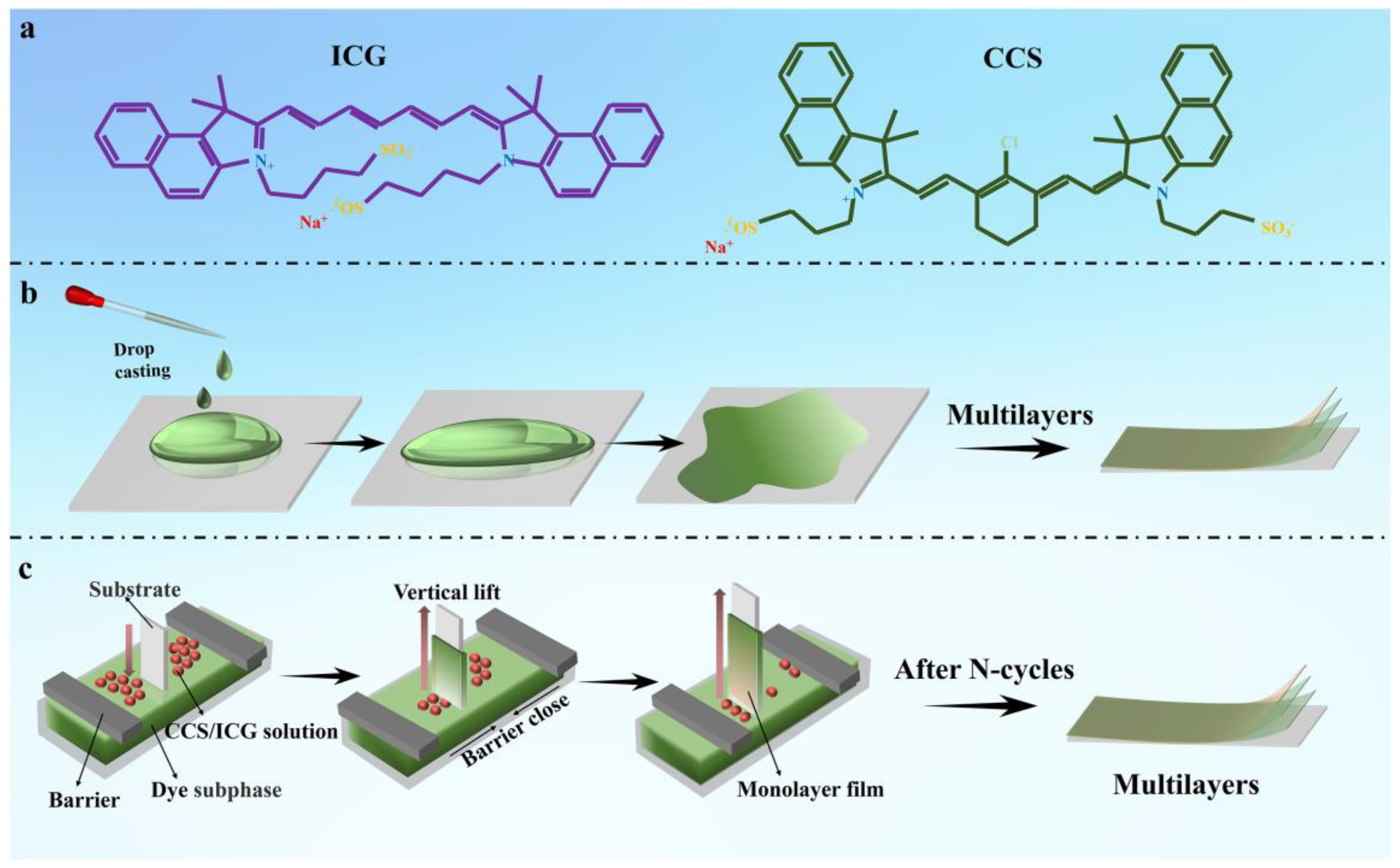
2.3. Preparation of ICS (CCS)/Dyes Langmuir Films

As shown in Figure 1b, to start with, the LB trough is cleaned thoroughly with ethanol and deionized water and left for 30 min to self–clean. For subsequent experiments, ICS(CCS) powder is dispersed in an alcohol solution (0.3 mg/mL). TsNiPc and TPPS are used as subphase solutions, both at a concentration of 1 × 10⁻³ mol/L. A microsyringe is used to add the ICS(CCS)/alcohol dispersion (200 μL) dropwise to the subphase surface. Surface pressure is measured using a tensiometer suspended on a Wilhelmy plate and fed back to the control system. After solvent evaporation, a stable air/water interface self–assembled structure is formed, which is compressed isothermally at a speed of 8 mm/min using a Langmuir–Blodgett barrier. The obtained π–A isotherm is recorded. For single–layer Langmuir films, vertical transfer is used. A freshly peeled transparent mica sheet is vertically fixed and immersed below the subphase liquid surface. The ICS(CCS)/alcohol dispersion is then dropped onto the subphase surface and allowed to spread for 20 min before slowly compressing to the target pressure (15 mN) at a speed of 8 mm/min. It is then lifted vertically at a speed of 1 mm/min until it is stopped, dried, then measured using AFM. Multilayer LB films are obtained through the horizontal transfer method, transferring X layers of LB film onto cleaned quartz and indium tin oxide (ITO) substrates.

2.4. Preparation of ICS (CCS)/Dyes Drop–Casting Films

As shown in Figure 1c, the different solid substrates should be washed repeatedly in advance using ethanol and ultrapure water. Then, 0.3 mg/mL spreading agent solution and 1 mol/L subphase solution should be mixed according to the volume ratio of 1:3, and then the solution should be dropped on the substrate. During this process, the size and number of drops should be controlled so that they are uniformly distributed on the substrate. Subsequently, the substrate should be placed in a constant–temperature and –humidity environment to control the diffusion and evaporation of the solution to form a uniform film.

3. Results and Discussion

The π–A isotherm of the LB film is presented in Figure 2. After optimizing the experimental conditions and considering the principle of variable unification, the spreading agent was prepared with a concentration of 0.3 mg/mL, and a volume of 200 µL was employed. The graph reveals that the CCS solution exhibits a higher surface pressure on the pure water subphase than the ICG solution, with a value of up to 31 mN/m. This phenomenon may be attributed to the poor water solubility of CCS molecules, which can spread more efficiently at the gas–liquid interface. However, when the subphase is TPPS solution, the surface pressure experiences a rapid increase as the single molecule area decreases to around 0.5 nm2 per molecule, ultimately reaching 22 mN/m. For CCS, the surface pressure can reach 25 mN/m on the TTPS subphase, but its starting point is delayed at approximately 0.25 nm2 per single molecule area. On the other hand, ICG demonstrates surface pressures of 37 mN/m and 21 mN/m on the TTPS and TsNiPc subphases, respectively. Both subphases have similar starting points, approximately at a single molecule area of 0.3 nm2. Nevertheless, ICG does not show an evident solid–liquid transition zone on the TPPS subphase, which could be associated with the solubility and dispersibility of ICG molecules on the TPPS surface [24].
Figure 3 presents the transmission electron microscopy images of LB and drop–casting films. As illustrated, the surface of the TsNiPc/CCS LB composite film displays a cross–linked mesh structure with a relatively uniform distribution, interspersed with similarly sized block–like structures. In contrast, its drop–casting film appears unevenly distributed, with irregularly shaped blocks that tend to stack and aggregate in large patches. The TsNiPc/ICG LB film exhibits a dense thin film that is relatively uniform, while its corresponding drop–casting film appears as stacked thin sheets. The TPPS/CCS LB film displays short rods or dotted structures, whereas its drop–casting film consists of irregularly shaped, elongated blocks that tend to stack and aggregate. The TPPS/ICG LB film shows a continuous thin film structure, while its drop–casting film has a porous structure. Overall, under the same conditions, LB composite films exhibit denser and more regular morphology than their drop–casting counterparts.
The surface morphology and nanostructure of two different types of composite films were further characterized using atomic force microscopy (AFM). The LB monolayer film was transferred at a surface pressure of 15 mN/m. Figure 4a shows the TsNiPc/CCS LB film, whose aggregate size was large, and the obvious cross–linked network structure in Figure 4a corresponds to the transmission image of the TsNiPc/CCS LB film. Figure 4b shows the TsNiPc/ICG LB film, which exhibited a uniform distribution of small particles. Figure 4c shows the TPPS/CCS LB film, which displayed aggregates of short rods or dotted structures, corresponding to TEM image of the TPPS/CCS LB film. In Figure 4d, a sheet–like structure similar to the TEM image of the TPPS/ICG LB film is observed. Furthermore, as shown in Figure 4a’–d’ of drop–casting films, most films are non–ordered (except the TPPS/CCS film), which usually consist of small aggregates. It is interesting that the TPPS/CCS drop–casting film shows a large number of cluster–like aggregates (Figure 4c’). This phenomenon may be due to the stronger electrostatic attraction of CCS, allowing its aggregates to attract each other.
In the process of utilizing composite films for specific applications such as catalytic electrolysis of water, they usually come into contact with aqueous solutions. Therefore, exploring the hydrophilicity and hydrophobicity of the films is also a crucial factor in studying their application performance [25,26,27]. In this experiment, two types of composite films were transferred onto clean quartz substrates and their hydrophilic properties were measured using a contact angle measurement instrument after drying at room temperature. To ensure experimental accuracy, five random locations were selected for contact angle measurement on each type of composite film, considering that the surface structure of the film has a significant impact on the contact angle. The results shown in Figure 5 indicate that the contact angles of composite films prepared using the same technique are similar, with small variations. However, LB films of the same material but prepared using different methods show significant differences in contact angles. For instance, for the TPPS/CCS composite film, the contact angle of the TPPS/CCS LB film is 39.0°, while that of the TPPS/CCS drop–casting film is 26.7°. The comparison of contact angles of the two composite films can be clearly observed in Figure 5. LB composite films prepared using LB technology have larger contact angles than those prepared using other methods (Figure 5e), indicating that their surfaces are more hydrophobic. In contrast, drop–casting films have the best hydrophilicity (Figure 5f). This phenomenon may be attributed to the orderly arrangement of molecules according to the hydrophilic end facing inward and the hydrophobic end facing outward during the process of molecule spreading and complex formation at the gas–liquid interface and transferring to the solid matrix during the preparation of composite films using LB technology. This results in more hydrophobic end groups on the outermost surface of the LB film.
The UV spectra of the two composite films produced with different methods were compared to explore their optical properties and aggregation states. As shown in Figure 6a, CCS dye solutions exhibited absorption bands at 396 nm and 475 nm while ICG dye solutions exhibited an absorption band at 390 nm. From Figure 6b, it can be seen that the TsNiPc solution’s characteristic absorption peak is located at 625 nm, with a weak shoulder peak at 658 nm, and the TPPS solution had a significant absorption peak at 434 nm. As shown in Figure 6c, compared with the absorption peak of the CCS dye solution (396 nm), the TPPS/CCS LB film’s characteristic absorption peak was red–shifted to 425 nm. This may be due to the presence of J–aggregates in the LB film, causing the characteristic absorption peak position to shift towards longer wavelengths. The characteristic peak of the TPPS/CCS drop–casting film was shifted similarly to that of the original TPPS solution, with the Q–band peak red–shifted from 644 nm to around 709 nm. Meanwhile, the B–band peak at 434 nm red–shifted to 494 nm, accompanied by a small shoulder peak at around 424 nm. Furthermore, comparing the TPPS/CCS LB film and TPPS/CCS drop–casting film, we can conclude that the drop–casting film exhibits a higher level of structural organization because the absorption bands are narrower compared to the corresponding bands of the TPPS/CCS LB film. As shown in Figure 6d, after forming the TPPS/ICG LB film, the characteristic peak was shifted from 434 nm to 426 nm, and a small shoulder peak appeared at 446 nm. This may be attributed to the presence of H–aggregates and a small amount of J–aggregates in the thin film. The UV spectra of the TPPS/ICG drop–casting were similar to those of the TPPS/CCS drop–casting film, indicating the possible presence of both J– and H–aggregates. Comparing the TPPS/ICG LB film and TPPS/ICG film, we can confirm the existence of H–aggregates and a small amount of J–aggregates in films obtained through the two methods. Similarly, as shown in Figure 6e, the TsNiPc/CCS LB film’s characteristic absorption peak was shifted from 625 nm to 617 nm, indicating the presence of H–aggregates. After the TsNiPc and CCS molecules were co–deposited to form a composite film, distinct absorption peaks appeared at 490 nm and 707 nm in the drop–casting film, indicating the presence of both H– and J–aggregates in the composite film. Comparing the TsNiPc/ICG LB film and TsNiPc/ICG drop–casting film, we found that composite films with different aggregation states can be obtained through different methods. Moreover, Figure 6f shows that the characteristic peak of the TsNiPc/ICG LB film was also blue–shifted from 625 nm to 607 nm, which may be due to the presence of H–aggregates in the TsNiPc/ICG LB film. In the case of the TsNiPc/ICG drop–casting film, the peak was shifted from 625 nm to 609 nm, indicating the formation of an H–aggregate. These UV spectral data indicated that dye molecules and spreading agent molecules spontaneously arrange themselves into different aggregation states at the gas–liquid interface through a series of non–covalent intermolecular interactions.
The optoelectronic response characteristics of the LB composite films and drop–casting films were tested. ITO conductive glass coated with LB film was used as the optoelectronic anode, a Hg/HgO electrode as the reference electrode and a platinum sheet as the counter electrode. Additionally, 1 M KOH solution was chosen as the electrolyte solution. After connecting the electrochemical workstation and setting the experimental parameters, the optoelectronic conversion efficiency of the composite film was monitored. The experimental results are shown in Figure 7. The linear scanning voltammetry (LSV) curve in Figure 7a reflects the size of the electrode oxygen evolution potential. It can be seen from the graph that after the potential reaches a certain value, the optoelectronic current signals of all four composite films sharply increase, indicating that all composite films can achieve charge separation and transfer. Among these films, the TsNiPc/CCS composite film has the best reaction activity, and the anodic current rapidly increases above 0.5 V potential. To better understand the charge separation performance of the composite film, the instantaneous optoelectronic current changes of the composite film were tested using chronoamperometry, with the time interval between turning on/off the light source being thirty seconds. As shown in Figure 7b, the optoelectronic current signal change trends of the TPPS/CCS, TPPS/ICG and TsNiPc/CCS composite films all increase when there is light and decrease when there is no light. However, although the TPPS/CCS and TsNiPc/CCS composite films can respond to light signals, they are not stable and regular, and do not show periodic regular changes. This may be because after the carrier separation, rapid recombination occurs [28]. In contrast, the TPPS/ICG composite film responds very quickly and stably to light signals, which is likely because the specific structure in the TPPS/ICG composite film can inhibit the recombination of electron–hole pairs, which is conducive to rapid charge transfer. The optoelectronic electron transfer characteristics of the composite film were better understood through electrochemical impedance spectroscopy (EIS) spectra, and Figure 7c,d show the EIS of the LB composite films. The diameter of the semicircle represents the electronic transfer resistance (Ret), reflecting the degree of restricted diffusion of the oxygen reduction probe through the system, while the arc curve represents the charge transfer between the electrolyte solution and the electrode [29]. The TsNiPc/CCS and TsNiPc/ICG composite films exhibit the smallest and largest semicircles, respectively, indicating that the conductivity of the TsNiPc/CCS composite film is higher, the electron transfer efficiency is high and the electrochemical reaction is also more likely to occur on its surface.
Figure 8 shows the optoelectronic response characteristics of the drop–casting films. First, the LSV curve (Figure 8a) was observed. Similar to the LB films, the current signal of the TsNiPc/CCS drop–casting film sharply increased in current density after a potential of 0.5 V. However, its overall signal expression was weaker than that of the LB composite film. This may be due to the more regular and ordered J–type aggregates present in the LB film structure, which increase the spectral absorption range and promote optoelectronic electron transfer. Next, the separation and recombination of electron–hole pairs and the photovoltaic current intensity in the drop–casting film were studied and monitored. The results are shown in Figure 8b,c, indicating that the current signal of the TsNiPc/CCS drop–casting film was weak. The Voc of the PEC cell represents the Fermi level difference between the photoactive material and the counter electrode. Under no–light conditions, the electrode potential is determined by the redox equilibrium. At open circuit voltage, a large number of photo–generated electrons are transferred and accumulate in the composite film under illumination, so the Fermi level shifts towards a more negative potential, resulting in an increase in open circuit voltage. After turning off the light source, the originally accumulated electrons begin to slowly release due to the presence of electron acceptor substances in the electrolyte, causing the open circuit voltage to decrease. Therefore, monitoring the open circuit voltage can better understand the charge separation efficiency. From the graph, it can be seen that the photovoltaic signal change amplitude of the TPPS/ICG composite film in the drop–casting film was larger, indicating that the survival time of photo–generated electrons in the TPPS/ICG was longer and the accumulation was more obvious. However, the stability of the TPPS/ICG was poor, possibly due to its low electron–hole pair separation efficiency. The reaction activity of the TPPS/CCS and TsNiPc/CCS composite films was similar and showed periodic regular changes. Figure 8d shows the EIS of the drop–casting films, from which it can be seen that the TPPS/CCS composite film had the smallest semicircle radius, indicating a higher electron transfer efficiency. Overall, after comparing the optoelectronic properties of composite films prepared using different methods, it was found that the LB technology–produced composite film had better optoelectronic properties in terms of the intensity of generated photocurrent signals and the stability of their photovoltaic conversion. The better optoelectronic properties of LB films may be attributed to the large number of J–aggregates present internally, which can expand the light absorption band and achieve better optoelectronic conversion.

4. Conclusions

In this work, TsNiPc/CCS, TsNiPc/ICG, TPPS/CCS and TPPS/ICG composite films were prepared using LB technology and drop–casting technology, respectively. The morphology, spectral characterization and photoelectric properties of the composite films prepared using LB technology and drop–casting technology were compared systematically. By comparison, the morphology of the composite films prepared using LB technology are smoother and denser, the roughness is the lowest and the hydrophobicity is also better. Furthermore, in the photoelectric performance test, the LB composite films show higher–intensity photocurrent signal and more stable photoelectric conversion under the same test conditions, but the drop–casting films are poor. This may be attributed to the existence of a large number of J–aggregates in the LB films, which can expand the light absorption band and achieve better photoelectric conversion.

Author Contributions

J.C.: Performed the experiments and wrote the paper. N.L.: Data curation. L.L.: Data curation. C.W.: Data curation. D.H.: Data curation. T.J.: Designed the experiments, review and editing. All authors have read and agreed to the published version of the manuscript.

Funding

This study was supported by National Natural Science Foundation of China (No. 22072127) and the Natural Science Foundation of Hebei Province (No. B2021203016).

Institutional Review Board Statement

Not applicable.

Informed Consent Statement

Not applicable.

Data Availability Statement

Not applicable.

Conflicts of Interest

The authors declare no conflict of interest.

References

  1. Niu, D.; Ji, L.; Ouyang, G.; Liu, M. Histidine proton Shuttle–Initiated switchable inversion of circularly polarized luminescence. ACS Appl. Mater. Interfaces 2020, 12, 18148–18156. [Google Scholar] [CrossRef] [PubMed]
  2. Li, R.; Wang, L.; Dang, J.; Mi, L.; Han, J.; Mao, M.; Chen, B.; Liu, H. Reconfigurable and tunable photo–controlled hydrogrl using hydrogen bonding to drive molecule self–assembly and cross–linking. J. Mater. Sci. 2020, 55, 14740–14750. [Google Scholar] [CrossRef]
  3. Li, P.; Xu, G.; Wang, N.; Guan, B.; Zhu, S.; Chen, P.; Liu, M. 0D, 1D, and 2D Supramolecular Nanoassemblies of a Porphyrin: Controllable Assembly, and Dimensionality–Dependent Catalytic Performances. Adv. Funct. Mater. 2021, 31, 2100367. [Google Scholar] [CrossRef]
  4. Chang, R.; Zou, Q.; Zhao, L.; Liu, Y.; Xing, R.; Yan, X. Amino Acid–Encoded Supramolecular Photothermal Nanomedicine for Enhanced Cancer Therapy. Adv. Mater. 2022, 34, 2200139. [Google Scholar] [CrossRef]
  5. Xing, R.; Zou, Q.; Yuan, C.; Zhao, L.; Chang, R.; Yan, X. Self–Assembling Endogenous Biliverdin as a Versatile Near–Infrared Photothermal Nanoagent for Cancer Theranostics. Adv. Mater. 2019, 31, 1900822. [Google Scholar] [CrossRef] [PubMed]
  6. Yang, Y.; Yang, X.; Yang, W.; Li, S.; Xu, J.; Jiang, Y. Ordered and ultrathin reduced graphene oxide LB films as hole injection layers for organic light–emitting diode. Nanoscale Res. Lett. 2014, 9, 537. [Google Scholar] [CrossRef] [Green Version]
  7. Giner–Casares, J.; Brezesinski, G.; Möhwald, H. Langmuir monolayers as unique physical models. Curr. Opin. Colloid Interface Sci. 2014, 19, 176–182. [Google Scholar] [CrossRef]
  8. Nie, H.; Dou, X.; Tang, Z.; Jang, H.; Huang, J. High–Yield Spreading of Water–Miscible Solvents on Water for Langmuir–Blodgett Assembly. J. Am. Chem. Soc. 2015, 137, 10683–10688. [Google Scholar] [CrossRef]
  9. Bettini, S.; Pagano, R.; Valli, L.; Giancane, G. Spectroscopic Investigation of the Selective Interaction of Mercuric and Cupric Ions with a Porphyrin Active Layer. J. Phys. Chem. C 2014, 118, 12384–12390. [Google Scholar] [CrossRef]
  10. Ermakova, E.V.; Koroleva, E.O.; Shokurov, A.V.; Arslanov, V.V.; Bessmertnykh–Lemeune, A. Ultra–thin film sensors based on porphyrin–5–ylphosphonate diesters for selective and sensitive dual–channel optical detection of mercury(II) ions. Dye. Pigment. 2021, 186, 108967. [Google Scholar] [CrossRef]
  11. Graewe, L.; Hupfer, M.L.; Schulz, M.; Mahammed, A.; Gross, Z.; Presselt, M. Supramolecular Control of Photonic Response and Sensing of Nitricoxide using Iron(III) Corrole Monolayers and Their Stacks. ChemPlusChem 2023, 88, e202200260. [Google Scholar] [CrossRef] [PubMed]
  12. Matsumoto, M.; Tachibana, H.; Sato, F.; Terrettaz, S. Photoinduced Self–Organization in Langmuir–Blodgett Films. J. Phys. Chem. B 1997, 101, 702–704. [Google Scholar] [CrossRef]
  13. Tachibana, H.; Yamanaka, Y.; Sakai, H.; Abe, M.; Matsumoto, M. J–Aggregate formation and morphological change on UV irradiation of the Langmuir–Blodgett films of spiropyran. Mol. Cryst. Liq. Cryst. 2000, 345, 149–154. [Google Scholar] [CrossRef]
  14. Wang, C.; Li, N.; Bian, P.; Li, G.; Yang, J.; Li, Q.; Jiao, T. UV–response behavior and chiral structure determination of Langmuir–Blodgett films consisting of polypeptide and dye molecules. Colloids Surf. A 2022, 636, 128221. [Google Scholar] [CrossRef]
  15. Wang, R.; Yan, X.; Ge, B.; Zhou, J.; Wang, M.; Zhang, L.; Jiao, T. Facile Preparation of Self–Assembled Black Phosphorus–Dye Composite Films for Chemical Gas Sensors and Surface–Enhanced Raman Scattering Performances. ACS Sustain. Chem. Eng. 2020, 8, 4521–4536. [Google Scholar] [CrossRef]
  16. Gregory, B.W.; Vaknin, D.; Cotton, T.M.; Struve, W.S. Interfacial complexation of phospholipid Langmuir monolayers with water–soluble porphyrins and phthalocyanines: An X–ray reflectivity study. Thin Solid Film 1996, 284, 849–853. [Google Scholar] [CrossRef]
  17. Costa, S.M.B.; Andrade, S.M.; Togashi, D.M.; Paulo, P.M.R.; Laia, C.A.T.; Viseu, M.I.; da Silva, A.M.G. Optical spectroscopy and photochemistry of porphyrins and phthalocyanines. J. Porphyr. Phthalocyanines 2009, 13, 509–517. [Google Scholar] [CrossRef]
  18. Huc, V.; Armand, F.; Bourgoin, J.P.; Palacin, S. Covalent anchoring of phthalocyanines on silicon dioxide surfaces: Building up mono– and multilayers. Langmuir 2001, 17, 1928–1935. [Google Scholar] [CrossRef]
  19. Kroon, J.M.; Sudholter, E.J.R.; Schenning, A.; Nolte, R.J.M. Self–Organization of Amphiphilic Porphyrins at the Air–Water–Interface. Langmuir 1995, 11, 214–220. [Google Scholar] [CrossRef] [Green Version]
  20. Li, N.; Wang, C.; Li, L.; Hao, Z.; Gu, J.; Wang, M.; Jiao, T. Chemical gas sensor, surface enhanced Raman scattering and photoelectrics of composite Langmuir–Blodgett films consisting of polypeptide and dye molecules. Colloids Surf. A 2023, 663, 131067. [Google Scholar] [CrossRef]
  21. Acikbas, Y.; Erdogan, M.; Capan, R.; Ozkaya, C.; Baygu, Y.; Kabay, N.; Gök, Y. Preparation of Zinc (II) phthalocyanine-based LB thin film: Experimental characterization, the determination of some optical properties and the investigation of the optical sensing ability. Optik 2021, 245, 167661. [Google Scholar] [CrossRef]
  22. Dutta, P.; Rai, R.; Pandey, S. Effect of ionic liquid on J–aggregation of meso–Tetrakis (4–sulfonatophenyl) porphyrin within aqueous mixtures of poly(ethyleneglycol). J. Phys. Chem. B 2011, 115, 3578–3587. [Google Scholar] [CrossRef] [PubMed]
  23. Ray, K.; Nakahara, H. Adsorption of sulforhodamine dyes in cationic Langmuir– blodgett films: Spectroscopic and structural studies. J. Phys. Chem. B 2002, 106, 92–100. [Google Scholar] [CrossRef]
  24. Desmettre, T.; Devoisselle, J.; Mordon, S. Fluorescence Properties and Metabolic Features of Indocyanine Green (ICG) as Related to Angiography. Surv. Ophthalmol. 2000, 45, 15–27. [Google Scholar] [CrossRef] [PubMed]
  25. Wang, J.; Liu, K.; Yan, L.; Wang, A.; Bai, S.; Yan, X. Trace solvent as a predominant factor to tune dipeptide self–assembly. ACS Nano 2016, 10, 2138–2143. [Google Scholar] [CrossRef] [PubMed]
  26. Pan, Y.; Chen, Y.; Wu, K.; Chen, Z.; Liu, S.; Cao, X.; Cheong, W.; Meng, T.; Luo, J.; Zheng, L.; et al. Regulating the coordination structure of single–atom Fe–NxCy catalytic sites for benzene oxidation. Nat. Commun. 2019, 10, 4290. [Google Scholar] [CrossRef] [PubMed] [Green Version]
  27. Lu, X.; Hu, Y.; Guo, J.; Wang, C.; Chen, S. Fiber-Spinning-Chemistry Method toward In Situ Generation of Highly Stable Halide Perovskite Nanocrystals. Adv. Sci. 2019, 6, 1901694. [Google Scholar] [CrossRef] [Green Version]
  28. Kahnt, A.; Kärnbratt, J.; Esdaile, L.; Hutin, M.; Sawada, K.; Anderson, H.; Albinsson, B. Temperature Dependence of Charge Separation and Recombination in Porphyrin Oligomer–Fullerene Donor–Acceptor Systems. J. Am. Chem. Soc. 2011, 133, 9863–9871. [Google Scholar] [CrossRef]
  29. Zheng, Q.; Wang, T.; Li, X.; Qian, H.; Bian, X.; Li, X.; Bai, H.; Ding, S.; Yan, Y. Femtomolar and locus-specific detection of N6-methyladenine in DNA by integrating double-hindered replication and nucleic acid-functionalized MB@Zr-MOF. J. Nanobiotechnol. 2021, 19, 408. [Google Scholar] [CrossRef]
Figure 1. (a) structural formulas of CCS and ICG molecules (b) Schematic preparation process of drop–casting films and (c) schematic preparation process of LB films.
Coatings 13 01423 g001
Figure 2. Surface pressure–area isotherms (π–A) of the synthesized Langmuir films: (a) CCS solution spread on the surface of different subphases (water subphase, TsNiPc subphase and TPPS subphase) and (b) ICG solution spread on the surface of different subphases (water subphase, TsNiPc subphase and TPPS subphase (concentration: 1 × 10⁻³ mol/L).
Coatings 13 01423 g002
Figure 3. TEM images (copper grid surface) of (a) TsNiPc/CCS LB film and (a’) TsNiPc/CCS drop–casting film, (b) TsNiPc/ICG LB film and (b’) TsNiPc/ICG drop–casting film, (c) TPPS/CCS LB film and (c’) TPPS/CCS drop–casting film, (d) TPPS/ICG LB film and (d’) TPPS/ICG drop–casting film.
Coatings 13 01423 g003
Figure 4. AFM images (mica surface) of (a) TsNiPc/CCS LB film and (a’) TsNiPc/CCS drop–casting film, (b) TsNiPc/ICG LB film and (b’) TsNiPc/ICG drop–casting film, (c) TPPS/CCS LB film and (c’) TPPS/CCS drop–casting film, (d) TPPS/ICG LB film and (d’) TPPS/ICG drop–casting film.
Coatings 13 01423 g004
Figure 5. Contact angle of (a) TsNiPc/CCS LB films, (b) TsNiPc/ICG LB films, (c) TPPS/CCS LB films and (d) TPPS/ICG LB films; (a’) TsNiPc/CCS drop–casting films, (b’) TsNiPc/ICG drop–casting films; (c’) TPPS/CCS drop–casting films and (d’) TPPS/ICG drop–casting films; contact angle of (e) LB films and (f) drop–casting films.
Coatings 13 01423 g005
Figure 6. UV–vis spectra of (a) CCS and ICG solution, (b) TPPS and TsNiPc solution, (c) TPPS/CCS LB and drop–casting films, (d) TPPS/ICG LB and drop–casting films, (e) TsNiPc/CCS LB and drop–casting films and (f) TsNiPc/ICG LB and drop–casting films.
Coatings 13 01423 g006
Figure 7. (a) LSV; (b) I–t curve; (c) and (d) EIS of TsNiPc/CCS, TsNiPc/ICG, TPPS/CCS and TPPS/ICG LB films.
Coatings 13 01423 g007
Figure 8. (a) LSV; (b) and (c) I–t curve; (d) EIS of TsNiPc/CCS, TsNiPc/ICG, TPPS/CCS and TPPS/ICG drop–casting films.
Coatings 13 01423 g008
Disclaimer/Publisher’s Note: The statements, opinions and data contained in all publications are solely those of the individual author(s) and contributor(s) and not of MDPI and/or the editor(s). MDPI and/or the editor(s) disclaim responsibility for any injury to people or property resulting from any ideas, methods, instructions or products referred to in the content.

