1. Introduction
Self–assembly refers to the process through which the component structure of a system changes from simple to complex and from disorder to order without human intervention. Self–assembly technology is widely used in the preparation of functional thin film materials because of its controllable size, composition and morphology. The development of supramolecular self–assembled film materials is very rapid and has gradually led to multilevel, dynamic and controlled self–assembly, which plays an important role in separation and analysis, nanotechnology and biomedicine [
1,
2,
3,
4,
5]. In particular, ordered ultrathin films play an important role in the ordered supramolecular assembly at the interface.
Specifically, Langmuir–Blodgett (LB) technology provides an effective method to generate highly ordered molecular films [
6,
7,
8]. LB technology can transfer single molecules from the subphase to solid substrate to form uniform films [
9,
10,
11]. In addition to the traditional amphiphilic molecules, many non–amphiphilic functional materials, such as non–long–chain substituted porphyrins, phthalocyanines, conductive polymers and other molecules, are gradually being introduced into LB films [
12,
13,
14]. From the literature, phthalocyanine molecules can form stable monolayers at the gas/liquid interface through electrostatic interactions [
15,
16,
17,
18,
19,
20,
21]. For example, Nickel phthalocyanine tetrasodium sulfonate (TsNiPc) molecules are widely used in photoelectric sensing devices, nano–electronic devices and molecular sensors because of their good photoelectric sensing performance. Here, the change in aggregation state directly affects their optoelectronic properties. Tetraphenylporphyrin tetrasulfonic acid hydrate (TPPS) has special dye properties, and it is easier to form different aggregation states with it under the influence of different pH environments. However, the change in aggregation degree of TPPS under different influences will have a direct impact on its photoelectric properties [
22]. For example, Wang et al. prepared LB composite films through self–assembly using phthalocyanine dye molecules and the two–dimensional material black phosphorus [
23]. The prepared composite LB films had adjustable structure and thickness and exhibited good acid–base gas response, SERS and photocurrent generation properties. Bian et al. successfully prepared an orderly and uniform composite LB film with adjustable structures and thickness based on novel organic small molecules composited with TsNiPc and TPPS subphases. The photoelectric conversion properties of composite films were also investigated. The results demonstrate that films transferred to the surface of substrates in different aggregated morphologies exhibit different photoelectrochemical performance [
21].
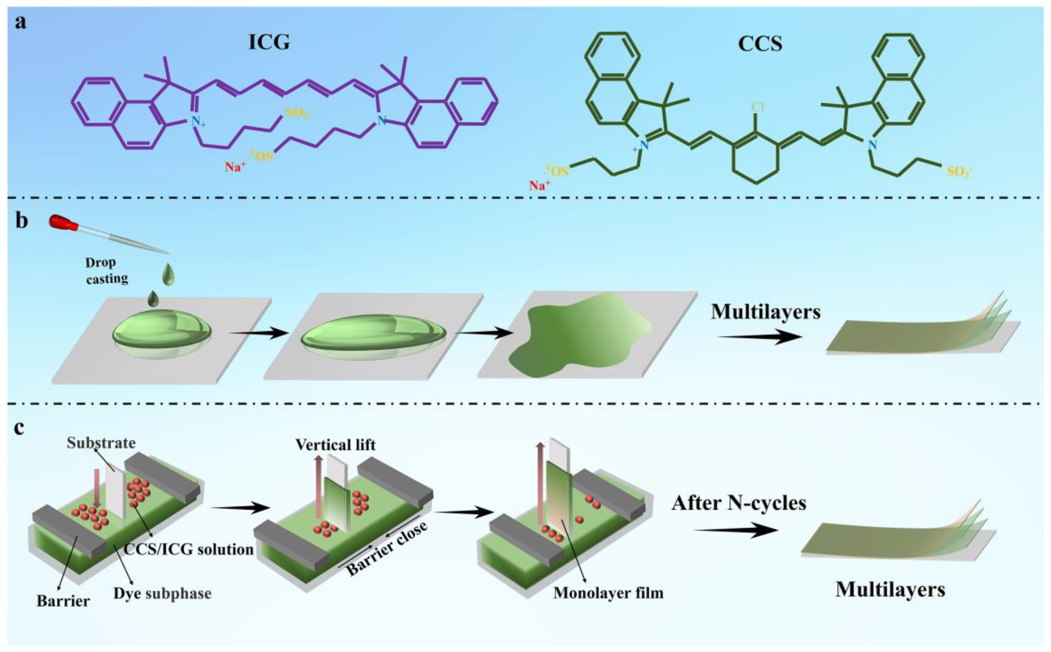
In this work, after a series of studies on the interface coordination of LB films, we selected two amphiphilic molecules with sulfonic acid groups, indocyanine green (ICG) and a derivative of indocyanine green (CCS) (
Figure 1a). A stable monolayer film can be formed at the gas–liquid interface, and then the film can be transferred to various substrates to study the preparation and photoelectric properties of LB films. In addition, the drop–casting process is a much simpler film forming process than other film forming processes. Because of its simplicity, ease of control, low cost and high material utilization, the drop–casting process is widely used in the fields of optoelectronics, biomedicine and energy. Therefore, we have taken the different aggregation forms of dyes as a starting point and further compared the differences of film materials formed using the two methods.
3. Results and Discussion
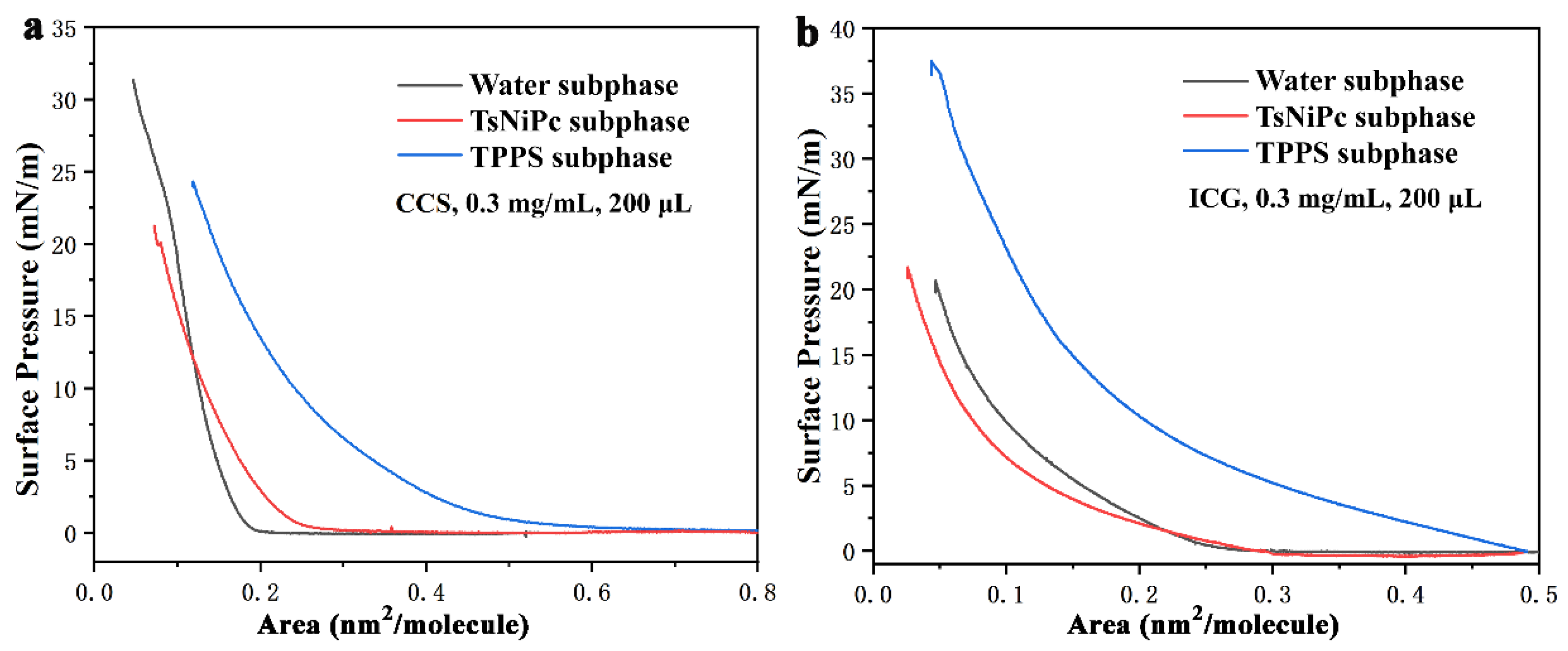
The π–A isotherm of the LB film is presented in
Figure 2. After optimizing the experimental conditions and considering the principle of variable unification, the spreading agent was prepared with a concentration of 0.3 mg/mL, and a volume of 200 µL was employed. The graph reveals that the CCS solution exhibits a higher surface pressure on the pure water subphase than the ICG solution, with a value of up to 31 mN/m. This phenomenon may be attributed to the poor water solubility of CCS molecules, which can spread more efficiently at the gas–liquid interface. However, when the subphase is TPPS solution, the surface pressure experiences a rapid increase as the single molecule area decreases to around 0.5 nm
2 per molecule, ultimately reaching 22 mN/m. For CCS, the surface pressure can reach 25 mN/m on the TTPS subphase, but its starting point is delayed at approximately 0.25 nm
2 per single molecule area. On the other hand, ICG demonstrates surface pressures of 37 mN/m and 21 mN/m on the TTPS and TsNiPc subphases, respectively. Both subphases have similar starting points, approximately at a single molecule area of 0.3 nm
2. Nevertheless, ICG does not show an evident solid–liquid transition zone on the TPPS subphase, which could be associated with the solubility and dispersibility of ICG molecules on the TPPS surface [
24].
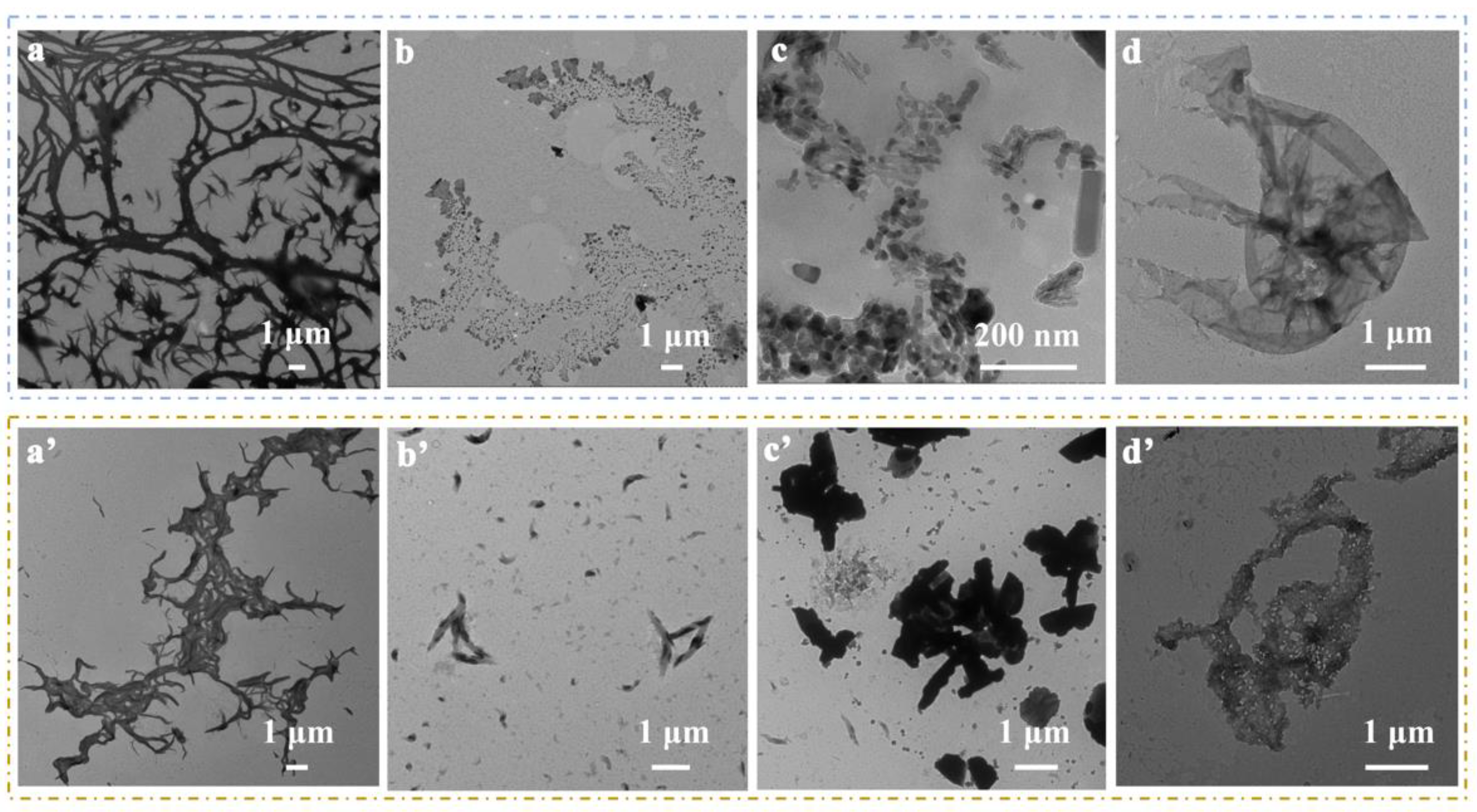
Figure 3 presents the transmission electron microscopy images of LB and drop–casting films. As illustrated, the surface of the TsNiPc/CCS LB composite film displays a cross–linked mesh structure with a relatively uniform distribution, interspersed with similarly sized block–like structures. In contrast, its drop–casting film appears unevenly distributed, with irregularly shaped blocks that tend to stack and aggregate in large patches. The TsNiPc/ICG LB film exhibits a dense thin film that is relatively uniform, while its corresponding drop–casting film appears as stacked thin sheets. The TPPS/CCS LB film displays short rods or dotted structures, whereas its drop–casting film consists of irregularly shaped, elongated blocks that tend to stack and aggregate. The TPPS/ICG LB film shows a continuous thin film structure, while its drop–casting film has a porous structure. Overall, under the same conditions, LB composite films exhibit denser and more regular morphology than their drop–casting counterparts.
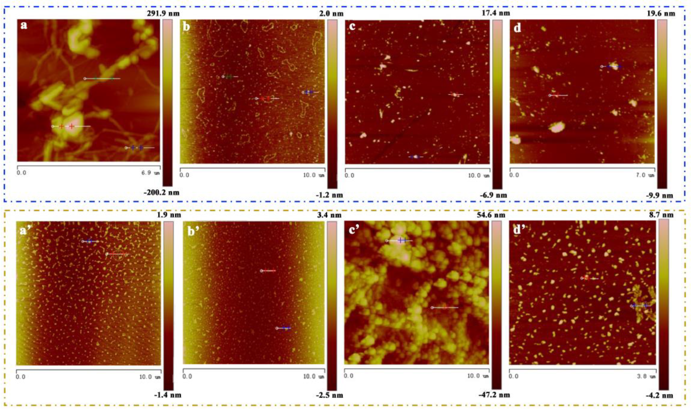
The surface morphology and nanostructure of two different types of composite films were further characterized using atomic force microscopy (AFM). The LB monolayer film was transferred at a surface pressure of 15 mN/m.
Figure 4a shows the TsNiPc/CCS LB film, whose aggregate size was large, and the obvious cross–linked network structure in
Figure 4a corresponds to the transmission image of the TsNiPc/CCS LB film.
Figure 4b shows the TsNiPc/ICG LB film, which exhibited a uniform distribution of small particles.
Figure 4c shows the TPPS/CCS LB film, which displayed aggregates of short rods or dotted structures, corresponding to TEM image of the TPPS/CCS LB film. In
Figure 4d, a sheet–like structure similar to the TEM image of the TPPS/ICG LB film is observed. Furthermore, as shown in
Figure 4a’–d’ of drop–casting films, most films are non–ordered (except the TPPS/CCS film), which usually consist of small aggregates. It is interesting that the TPPS/CCS drop–casting film shows a large number of cluster–like aggregates (
Figure 4c’). This phenomenon may be due to the stronger electrostatic attraction of CCS, allowing its aggregates to attract each other.
In the process of utilizing composite films for specific applications such as catalytic electrolysis of water, they usually come into contact with aqueous solutions. Therefore, exploring the hydrophilicity and hydrophobicity of the films is also a crucial factor in studying their application performance [
25,
26,
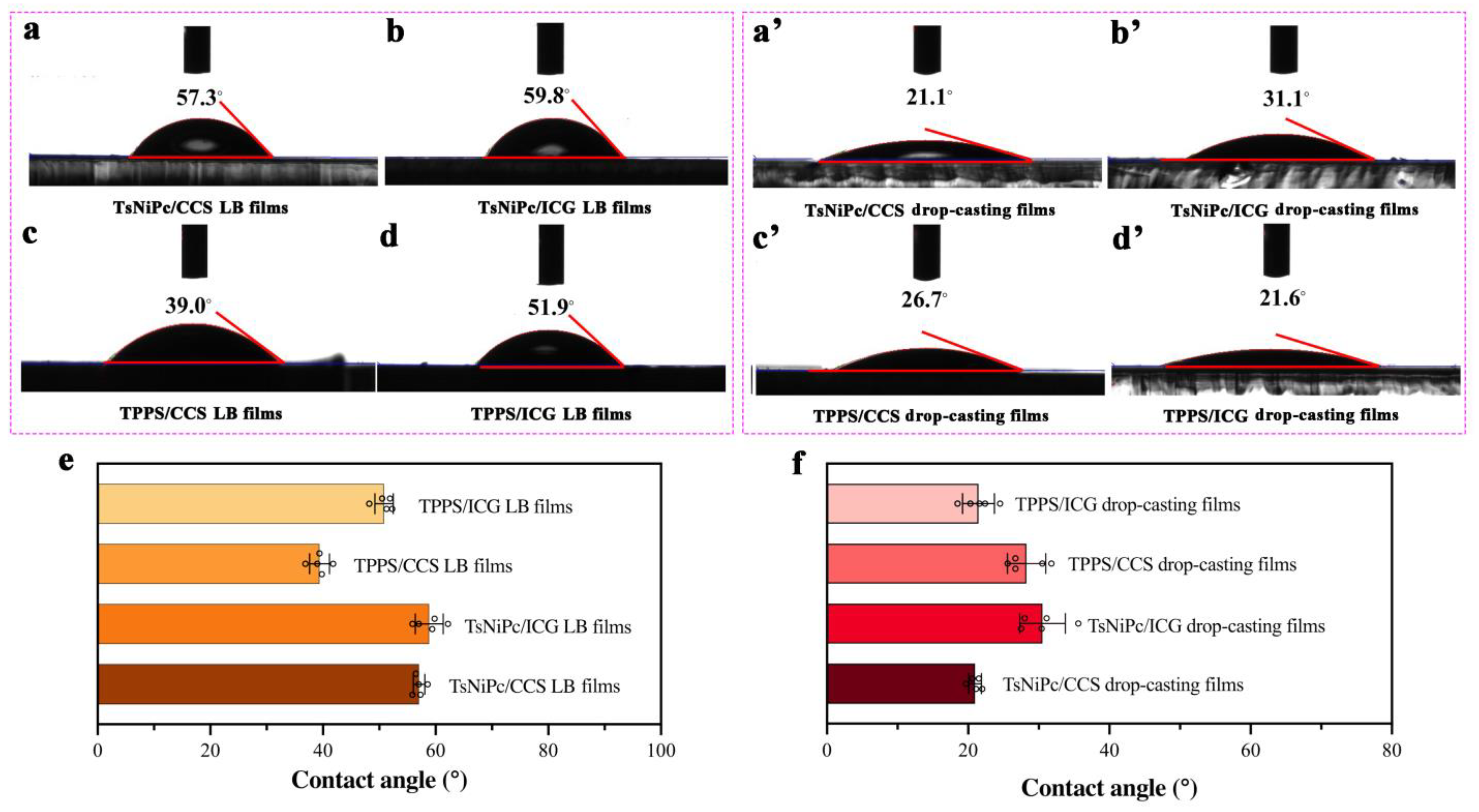
27]. In this experiment, two types of composite films were transferred onto clean quartz substrates and their hydrophilic properties were measured using a contact angle measurement instrument after drying at room temperature. To ensure experimental accuracy, five random locations were selected for contact angle measurement on each type of composite film, considering that the surface structure of the film has a significant impact on the contact angle. The results shown in
Figure 5 indicate that the contact angles of composite films prepared using the same technique are similar, with small variations. However, LB films of the same material but prepared using different methods show significant differences in contact angles. For instance, for the TPPS/CCS composite film, the contact angle of the TPPS/CCS LB film is 39.0°, while that of the TPPS/CCS drop–casting film is 26.7°. The comparison of contact angles of the two composite films can be clearly observed in
Figure 5. LB composite films prepared using LB technology have larger contact angles than those prepared using other methods (
Figure 5e), indicating that their surfaces are more hydrophobic. In contrast, drop–casting films have the best hydrophilicity (
Figure 5f). This phenomenon may be attributed to the orderly arrangement of molecules according to the hydrophilic end facing inward and the hydrophobic end facing outward during the process of molecule spreading and complex formation at the gas–liquid interface and transferring to the solid matrix during the preparation of composite films using LB technology. This results in more hydrophobic end groups on the outermost surface of the LB film.
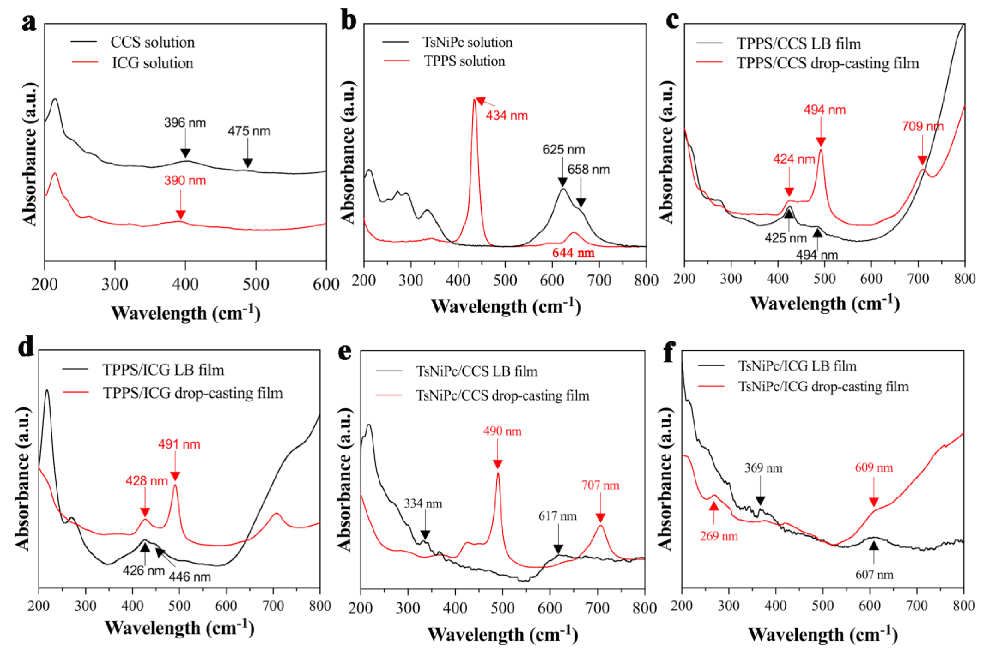
The UV spectra of the two composite films produced with different methods were compared to explore their optical properties and aggregation states. As shown in
Figure 6a, CCS dye solutions exhibited absorption bands at 396 nm and 475 nm while ICG dye solutions exhibited an absorption band at 390 nm. From
Figure 6b, it can be seen that the TsNiPc solution’s characteristic absorption peak is located at 625 nm, with a weak shoulder peak at 658 nm, and the TPPS solution had a significant absorption peak at 434 nm. As shown in
Figure 6c, compared with the absorption peak of the CCS dye solution (396 nm), the TPPS/CCS LB film’s characteristic absorption peak was red–shifted to 425 nm. This may be due to the presence of J–aggregates in the LB film, causing the characteristic absorption peak position to shift towards longer wavelengths. The characteristic peak of the TPPS/CCS drop–casting film was shifted similarly to that of the original TPPS solution, with the Q–band peak red–shifted from 644 nm to around 709 nm. Meanwhile, the B–band peak at 434 nm red–shifted to 494 nm, accompanied by a small shoulder peak at around 424 nm. Furthermore, comparing the TPPS/CCS LB film and TPPS/CCS drop–casting film, we can conclude that the drop–casting film exhibits a higher level of structural organization because the absorption bands are narrower compared to the corresponding bands of the TPPS/CCS LB film. As shown in
Figure 6d, after forming the TPPS/ICG LB film, the characteristic peak was shifted from 434 nm to 426 nm, and a small shoulder peak appeared at 446 nm. This may be attributed to the presence of H–aggregates and a small amount of J–aggregates in the thin film. The UV spectra of the TPPS/ICG drop–casting were similar to those of the TPPS/CCS drop–casting film, indicating the possible presence of both J– and H–aggregates. Comparing the TPPS/ICG LB film and TPPS/ICG film, we can confirm the existence of H–aggregates and a small amount of J–aggregates in films obtained through the two methods. Similarly, as shown in
Figure 6e, the TsNiPc/CCS LB film’s characteristic absorption peak was shifted from 625 nm to 617 nm, indicating the presence of H–aggregates. After the TsNiPc and CCS molecules were co–deposited to form a composite film, distinct absorption peaks appeared at 490 nm and 707 nm in the drop–casting film, indicating the presence of both H– and J–aggregates in the composite film. Comparing the TsNiPc/ICG LB film and TsNiPc/ICG drop–casting film, we found that composite films with different aggregation states can be obtained through different methods. Moreover,
Figure 6f shows that the characteristic peak of the TsNiPc/ICG LB film was also blue–shifted from 625 nm to 607 nm, which may be due to the presence of H–aggregates in the TsNiPc/ICG LB film. In the case of the TsNiPc/ICG drop–casting film, the peak was shifted from 625 nm to 609 nm, indicating the formation of an H–aggregate. These UV spectral data indicated that dye molecules and spreading agent molecules spontaneously arrange themselves into different aggregation states at the gas–liquid interface through a series of non–covalent intermolecular interactions.
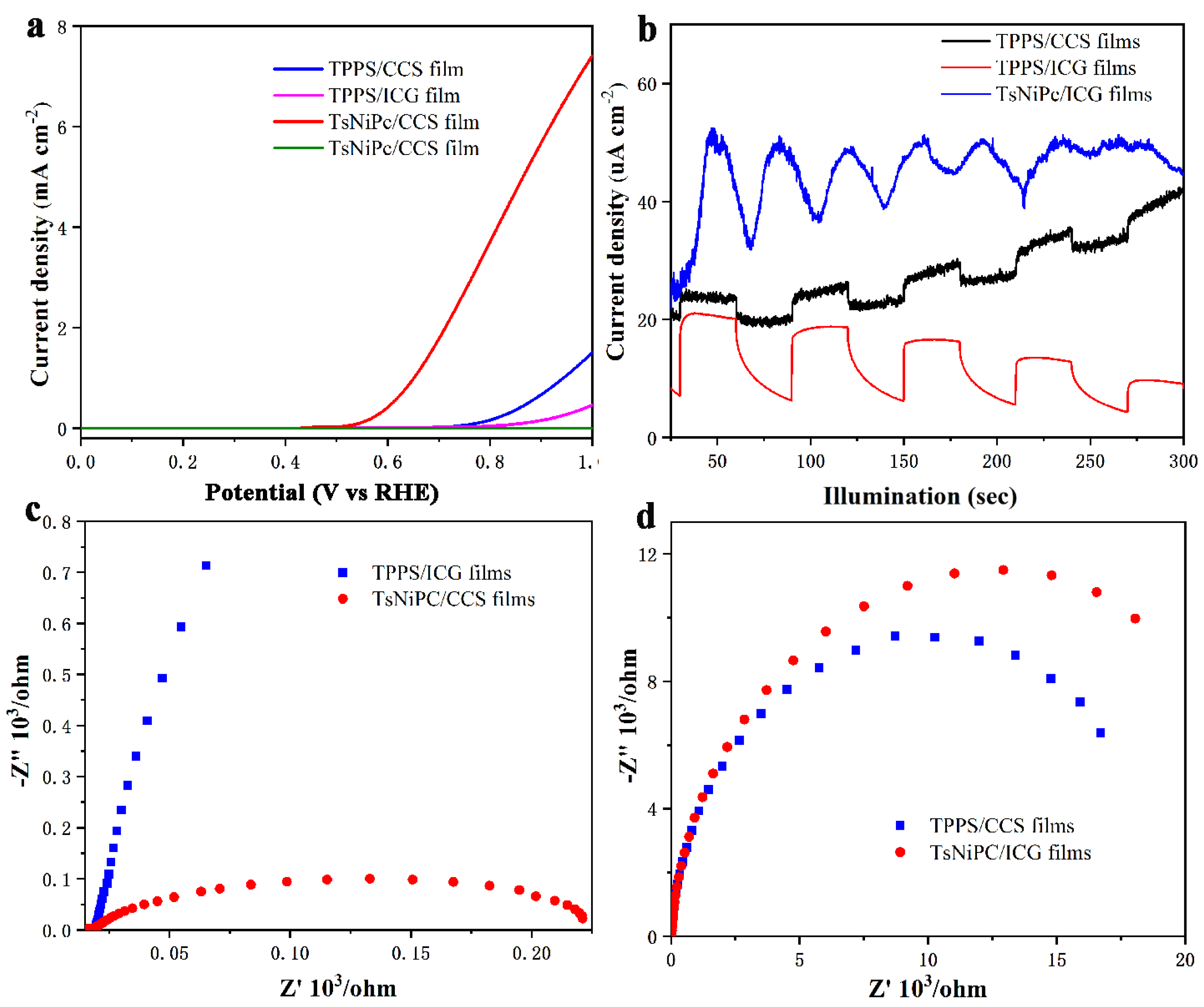
The optoelectronic response characteristics of the LB composite films and drop–casting films were tested. ITO conductive glass coated with LB film was used as the optoelectronic anode, a Hg/HgO electrode as the reference electrode and a platinum sheet as the counter electrode. Additionally, 1 M KOH solution was chosen as the electrolyte solution. After connecting the electrochemical workstation and setting the experimental parameters, the optoelectronic conversion efficiency of the composite film was monitored. The experimental results are shown in
Figure 7. The linear scanning voltammetry (LSV) curve in
Figure 7a reflects the size of the electrode oxygen evolution potential. It can be seen from the graph that after the potential reaches a certain value, the optoelectronic current signals of all four composite films sharply increase, indicating that all composite films can achieve charge separation and transfer. Among these films, the TsNiPc/CCS composite film has the best reaction activity, and the anodic current rapidly increases above 0.5 V potential. To better understand the charge separation performance of the composite film, the instantaneous optoelectronic current changes of the composite film were tested using chronoamperometry, with the time interval between turning on/off the light source being thirty seconds. As shown in
Figure 7b, the optoelectronic current signal change trends of the TPPS/CCS, TPPS/ICG and TsNiPc/CCS composite films all increase when there is light and decrease when there is no light. However, although the TPPS/CCS and TsNiPc/CCS composite films can respond to light signals, they are not stable and regular, and do not show periodic regular changes. This may be because after the carrier separation, rapid recombination occurs [
28]. In contrast, the TPPS/ICG composite film responds very quickly and stably to light signals, which is likely because the specific structure in the TPPS/ICG composite film can inhibit the recombination of electron–hole pairs, which is conducive to rapid charge transfer. The optoelectronic electron transfer characteristics of the composite film were better understood through electrochemical impedance spectroscopy (EIS) spectra, and
Figure 7c,d show the EIS of the LB composite films. The diameter of the semicircle represents the electronic transfer resistance (Ret), reflecting the degree of restricted diffusion of the oxygen reduction probe through the system, while the arc curve represents the charge transfer between the electrolyte solution and the electrode [
29]. The TsNiPc/CCS and TsNiPc/ICG composite films exhibit the smallest and largest semicircles, respectively, indicating that the conductivity of the TsNiPc/CCS composite film is higher, the electron transfer efficiency is high and the electrochemical reaction is also more likely to occur on its surface.
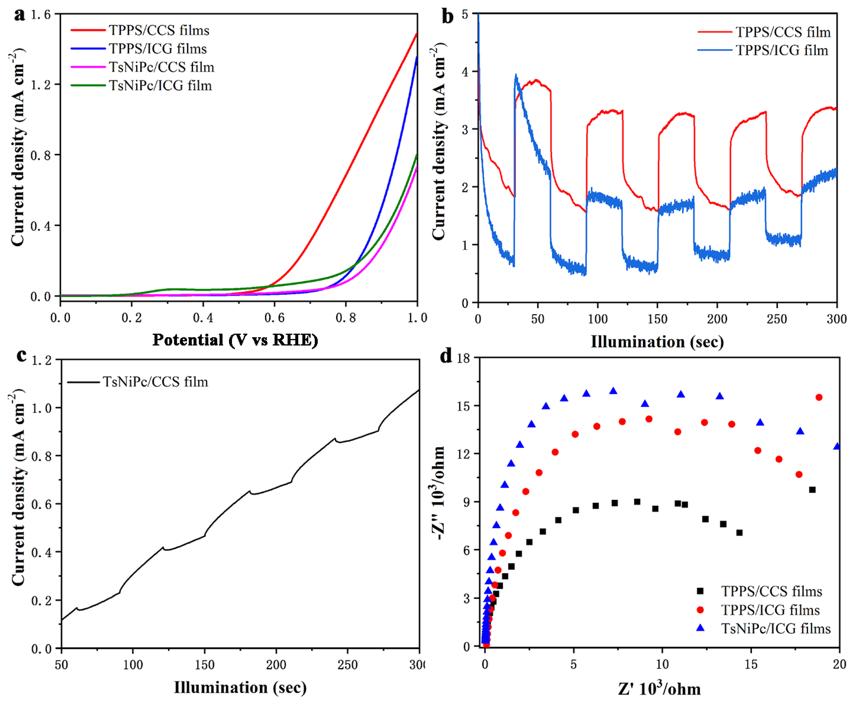
Figure 8 shows the optoelectronic response characteristics of the drop–casting films. First, the LSV curve (
Figure 8a) was observed. Similar to the LB films, the current signal of the TsNiPc/CCS drop–casting film sharply increased in current density after a potential of 0.5 V. However, its overall signal expression was weaker than that of the LB composite film. This may be due to the more regular and ordered J–type aggregates present in the LB film structure, which increase the spectral absorption range and promote optoelectronic electron transfer. Next, the separation and recombination of electron–hole pairs and the photovoltaic current intensity in the drop–casting film were studied and monitored. The results are shown in
Figure 8b,c, indicating that the current signal of the TsNiPc/CCS drop–casting film was weak. The Voc of the PEC cell represents the Fermi level difference between the photoactive material and the counter electrode. Under no–light conditions, the electrode potential is determined by the redox equilibrium. At open circuit voltage, a large number of photo–generated electrons are transferred and accumulate in the composite film under illumination, so the Fermi level shifts towards a more negative potential, resulting in an increase in open circuit voltage. After turning off the light source, the originally accumulated electrons begin to slowly release due to the presence of electron acceptor substances in the electrolyte, causing the open circuit voltage to decrease. Therefore, monitoring the open circuit voltage can better understand the charge separation efficiency. From the graph, it can be seen that the photovoltaic signal change amplitude of the TPPS/ICG composite film in the drop–casting film was larger, indicating that the survival time of photo–generated electrons in the TPPS/ICG was longer and the accumulation was more obvious. However, the stability of the TPPS/ICG was poor, possibly due to its low electron–hole pair separation efficiency. The reaction activity of the TPPS/CCS and TsNiPc/CCS composite films was similar and showed periodic regular changes.
Figure 8d shows the EIS of the drop–casting films, from which it can be seen that the TPPS/CCS composite film had the smallest semicircle radius, indicating a higher electron transfer efficiency. Overall, after comparing the optoelectronic properties of composite films prepared using different methods, it was found that the LB technology–produced composite film had better optoelectronic properties in terms of the intensity of generated photocurrent signals and the stability of their photovoltaic conversion. The better optoelectronic properties of LB films may be attributed to the large number of J–aggregates present internally, which can expand the light absorption band and achieve better optoelectronic conversion.

