Article

Spin Coating of Silica Nanocolloids on Mica: Self-Assembly of Two-Dimensional Colloid Crystal Structures and Thin Films

School of Engineering, Institute for Materials and Processes, The University of Edinburgh, Robert Stevenson Road, Edinburgh EH9 3FB, UK
*
Author to whom correspondence should be addressed.
Coatings 2023, 13(9), 1488; https://doi.org/10.3390/coatings13091488
Submission received: 26 July 2023 / Revised: 16 August 2023 / Accepted: 20 August 2023 / Published: 23 August 2023

Abstract

:
The viability of spin-coating methods for the self-assembly of 150 nm diameter silica nanocolloids into large crystal structures on mica was investigated using different colloidal concentrations, accelerations, and rotational speeds. The samples were imaged by atomic force microscopy (AFM) in intermittent contact mode. Low colloidal concentration led to a size-dependent ordering configuration. The largest nanocolloidal particles formed crystalline close-packed structures that were surrounded by increasingly smaller nanocolloids configured into more polycrystalline or amorphous formations. This phenomenon became increasingly suppressed by increasing colloidal concentration. Two dimensional-fast Fourier transform (2D-FFT) radially averaged profiles of the topography images revealed increasing interparticle spacing with increasing rotational acceleration, from close-packed structuring at low accelerations to increasingly spaced packing at high acceleration (>800 rpm/s). This behaviour is attributed to rapid liquid shedding from the increased acceleration. Analysis with radial distribution functions quantified the extent of ordering and revealed an optimum spin speed that caused the formation of large, highly crystalline structures. This optimum spin speed is governed by the relationship between the rotational speed and the liquid film thickness that affect the uniformity of the film and the magnitude of the capillary forces generated.

1. Introduction

The fabrication of surface structures that possess long-range periodicity at the nanoscale is of great interest to fields of science and technology in both research and industry. The traditional methods of nanofabrication are based on “top-down” techniques such as nano/microlithography [1,2,3], but “bottom-up” methodologies based on the self-assembly of nanocolloids or polymers are rapidly gaining ground [4,5,6,7,8,9,10,11,12,13,14]. Block-copolymer self-assembly is showing great promise for large-scale nanomanufacturing in both bulk and thin films; the nanopatterns formed can act as templates for the self-assembly of functional nanomaterials and thus pave the way to energy-harvesting devices, photonic metasurfaces, nanofiltration membranes, and antibacterial coatings [9,12,13]. Glynos et al. [10,11] have demonstrated the potential of polymer nanopatterning of mica surfaces with linear and star homopolymers that generate ordered structures under certain conditions of dip-coating. Nanocolloidal assembly, in particular (also called nanosphere lithography [15]), holds great promise for the bottom-up fabrication of periodic nanostructures [4,5]. Applications include catalysis [16], optoelectronics [17], surface-enhanced Raman spectroscopy (SERS) templates [18], photonics [19,20], photovoltaics [21], chemical sensors [22], biosensors [23], superhydrophobic surfaces [24], self-cleaning coatings [25], drug and gene delivery [26].
A variety of methods have been developed to create two-dimensional colloidal crystal structures; these methods include gravity sedimentation [27,28], electrophoretic deposition [29], droplet evaporation [30,31], solvent evaporation [32], wet coating [33] template-assisted assembly [34], acoustic field and shear assisted self-assembly [35], convective self-assembly [36], confined convective assembly [37,38,39], vertical deposition [40], Langmuir-Blodgett deposition [41], air-water interfacial floating [42], dip-coating [43,44]. Although these processes are suitable for laboratory-scale production, they are less useful for industrial processes due to the time scales and tedious fabrication processes involved. Past studies have demonstrated that the spin-coating process provides a simple and efficient method for the dispersion of small particles onto a substrate [16,17,45,46,47,48,49,50,51,52,53].
The spin-coating process for a colloidal suspension occurs in four distinct stages of development, the first two happening in quick succession while the latter two steps proceed over a much longer time frame. In the first stage, a colloidal fluid is deposited as a droplet onto the static substrate. The second stage is the acceleration of the substrate up to the programmed rotational speed, causing the droplet to spread out to form a film that rotates at approximately the same rate as the substrate. During this period, shear-induced ordering can occur. However, shear can have a dual influence on the order in colloidal suspensions. At high shear rates, it can disorder or melt a colloidal crystal, but at low shear rates or at low-amplitude oscillatory shear, it can induce order. Shear changes the growth kinetics, i.e., the induction time, density of nuclei, and crystal growth rate. In the third stage, when the target speed has been reached, the now spread-out film begins to thin globally. This thinning is controlled primarily by centrifugal and viscous shear forces. Finally, in the fourth stage, the film becomes sufficiently thin so that evaporation now dominates the behaviour of the film thickness. The transition from the third to the fourth stage is dependent on the volatility and other material properties of the suspension liquid. When the film thickness approaches that of the colloidal particle diameter, capillary forces play a dominant role in particle structuring.
Ogi et al. [54] accomplished a high surface coverage and a uniform monolayer of silica nanospheres (average diameters of 550 and 300 nm) on sapphire substrates using spin coating. They concluded that the balance between spin-coating speed and the solvent evaporation rate is of paramount importance for large areas of highly-packed silica particles. Khanna et al. [50] used silica nanospheres of average diameter of 200 nm for the fabrication of long-ranged monolayers on n-silicon substrates using a three-step spin-coating protocol. They also pinpointed the importance of the equilibrium between the spin-coating speed and solvent evaporation rate as they affect the centrifugal and capillary forces, respectively. Chen et al. [53] studied the effect of spin-coating speed, acceleration, and polystyrene (PS) particle diameter on their self-assembly in 2D colloidal-crystal films on silicon substrates. They used 223, 347, 509, and 1300 nm diameter spheres and optimised in detail the 509 nm-diameter system. Choi et al. [52] studied the effect of the solvent on the spin-coating process of 310 nm diameter silica nanospheres and revealed that N,N-dimethylformamide (DMF) offered improved wettability and slower evaporation rate compared to water (which is the most usual solvent) leading to high coverage, uniform close-packed nanocolloid monolayers on silicon substrates. Noppakuadrittidej et al. [48] recognised that high surface tension (or viscosity) solvents present the advantage of large inter-particle capillary forces and a low evaporation rate that allows the kinetics of close-packing to occur. However, they showed, using spin-coating of 611.13 ± 24.32 nm colloidal silica spheres, that low-surface tension solvents can also be employed, provided that the rotational speeds are low enough to decrease the evaporation rate and increase the colloidal crystal formation time. Chandramohan et al. [51] used 300 nm diameter PS nanospheres to spin-coat large-coverage uniform close-packed nanosphere monolayers on silicon wafers and to demonstrate the use of a spin-coating model, which employs two critical experimental parameters, the solid/liquid volume ratio and the spin-coating speed to fine-tune the process.
Colson et al. [55] were the first to systematically evaluate the spin-coating efficiency and quality of 490 nm diameter PS colloid assembly employing principal component analysis. Razaulla et al. [47] expanded the evaluation to more spin-coating parameters and, by using single-response and multiple-response linear regression modelling, identified optimised settings for a system of 390 nm diameter PS nanospheres spin-coated to silicon wafers. The general outcome revealed the required adjustment between high-enough acceleration and rpm rates to accomplish large coverage and low-enough shear forces and evaporation rates to accommodate the necessary mobility and time for highly-ordered close-packed structures. Lan et al. [46] synthesised silica nanocolloids of 196 nm diameter (standard deviation of ±40 nm) and fabricated close-packed colloidal monolayers that have shown promising properties for photonic and plasmonic nanostructures. More recently, Osipov et al. [45] employed spin coating and 300 nm PS colloidal particles on silicon substrates to fabricate a high-quality and coverage monolayer close-packed colloidal coating, which was used as a colloidal mask to produce nanoneedles by plasma etching.
Despite the abundance of submicron colloidal self-assembly studies using the highly efficient, fast, inexpensive, and straightforward technique of spin-coating, the lower limit of the nanocolloid diameter (<200 nm) remains unexplored. Furthermore, the effect of nanosphere polydispersity as a function of the nanocolloid concentration at sub-monolayer coverage has not been studied. This work explores the application of spin-coating techniques of 150 nm diameter silica colloidal nanoparticles on mica for the formation of well-ordered sub-monolayer and monolayer structures. Fumed silica colloidal particles of 150 nm in diameter suspended in water were deposited onto freshly cleaved mica squares using spin-coating protocols. Freshly cleaved mica provides an atomically flat, ultra-clean substrate which is ideal for the self-assembly of nanoparticles and nanocolloids. The colloidal suspension concentration, the rotational acceleration and the rotational speed were systematically varied in order to investigate how these parameters affect the structuring of the nanocolloidal nanoparticles. AFM techniques were used to investigate the fine structure of the resultant samples, contrary to the usually employed scanning electron microscopy (SEM). At low colloidal concentrations, the configuration of the nanocolloids is structured in a size-dependent ordering, a phenomenon that was emphasised by the polydispersity of our samples. At high concentrations (>25 g/L), this phenomenon was found to be suppressed by the surface particle density, and increasingly amorphous structuring occurred. Rotational acceleration affected the interparticle spacing. 2D-FFT of the AFM images [30,31,56] and the corresponding radially averaged profiles revealed that the interparticle spacing increased from close-packed structuring at low accelerations to increasingly spaced packing at high acceleration (>800 rpm/s). This behaviour was attributed to accelerated liquid shedding, which diminished the effectiveness of the attractive capillary forces and reduced the close-packed ordering of the nanocolloidal particles. Finally, for the rotational speed results, radial distribution functions were used to quantify the extent of ordering in the structuring of the nanocolloid particles. It was found that the rotational speed governs the “crystallinity” of the samples, with the appearance of an optimum rotational speed to maximise long-range crystal packing of the nanocolloidal particles for our experimental setup. This behaviour was attributed to both the effects of shear stress and the relationship between the rotational speed and the liquid film thickness, and hence the magnitude of the capillary forces generated.

2. Materials and Methods

2.1. Materials

Colloidal samples used in this study were aqueous dispersions of amorphous, non-porous fumed silica colloidal particles purchased from Bangs Laboratories, Inc. (Fishers, IN, USA). The nanocolloidal particle diameter was quoted by the manufacturer as 150 nm with a maximum coefficient of variation (CV) of 15%, giving a possible diameter range of 127.5 nm to 172.5 nm. Nanocolloids were supplied nonfunctionalised and suspended in deionised water from the manufacturer. 11 mm square mica sheets and metal mounting discs supplied by Fisher (Leicestershire, UK) were used for preparing sample substrates. All water used in the experiments was ultrapure water with a resistivity of 18.2 MΩ-cm at 25 °C. When submersed in water, the surfaces of both the silica nanocolloids and freshly cleaved mica have a negative charge. For the silica, this is due to the dissociation of silanol groups in the presence of water, and for the mica, a net negative charge is generated by the uneven charge distribution of potassium ions on the cleaved surfaces [57]. The colloidal samples were supplied in 10 mL vials of 50 g/L concentration (volume fraction = 2.27 × 10⁻²) from the manufacturer; where needed, these were further diluted by using ultrapure water to create dispersions of 25 g/L (φ = 1.14 × 10⁻⁴), 20 g/L (φ = 9.08 × 10⁻³), 15 g/L (φ = 6.81 × 10⁻³), 10 g/L (φ = 4.54 × 10⁻³) and 5 g/L (φ = 2.27 × 10⁻³). The nanocolloids’ ζ-potential was evaluated using a Malvern Zetasizer (Worcestershire, UK) and measured to be −47.3 mV. For storage purposes, the colloidal suspensions were kept in a refrigerator at 4 °C to inhibit any microbial growth.

2.2. Sample Preparation

All samples were prepared using a Spin150 spin coater (SPS-Europe, Putten, The Netherlands), with variations of the colloidal concentration, rotational acceleration, and speed. The mica squares were secured onto metal mounting disks using an adhesive tab and attached to the spin coater chuck via a vacuum seal. The mica was cleaved by using tape to remove the top sheet. This procedure was carried out inside a fume cupboard to minimise airborne pollutants from contaminating the surface [58]. Before the application of the colloidal suspension, the vials were agitated for 30 s to ensure an even distribution of the colloidal density throughout the suspension.
Three droplets (approximately 0.16 mL) of the colloidal suspension were deposited onto the freshly cleaved mica via a clean glass pipette. The droplet was observed to wet the entire mica substrate and pinned to the edges of the square. The spin coater hood was closed to prevent airborne particles from contaminating the sample. The droplet was left on the surface of the mica for approximately 30 s before the initiation of the spin-coating program. At low rotational speeds (<800 rpm), the colloidal suspension was observed to build up at the edge of the mica squares, in particular the corners. The magnitude of the build-up was dependent on the acceleration. All samples were spun at 8000 rpm for 6 min as a final step to eliminate this excess suspension and dry the samples. Upon completion of the spin-coating program, samples were removed from the spin coater and placed in a Petri dish inside a desiccator until imaged to reduce the adsorption of water from the atmosphere due to the highly hydrophilic nature of both silica and mica.
Each set of experimental runs had its own specific spin-coating program:
  • Program A: The first set of experiments had a rotational speed of 8000 rpm with a 50 rpm/s acceleration for a total of 520 s, resulting in a spin-up time of 160 s, with 8000 rpm maintained for 360 s.
  • Program B: The second set of experiments had a rotational speed of 4000 rpm with different rotational accelerations (200 to 1000 rpm/s in 200 rpm/s steps) for 120 s, followed by 8000 rpm for 360 s.
  • Program C: The third set of experiments had different rotational speeds (200 to 1000 rpm with 200 rpm steps, then 2000 to 8000 rpm with 2000 rpm steps) with a 1000 rpm/s acceleration for 120 s followed by 8000 rpm for 360 s.

2.3. Measurements

Imaging was performed using atomic force microscopy on a Veeco Multimode-Nanoscope IIIa AFM (Santa Barbara, CA, USA) under soft tapping mode™ regime (the cantilever tip makes intermediate contact with the surface). Silicon nitride cantilevers from Windsor Scientific Ltd. (Berkshire, UK) at a resonance frequency of approximately 320 kHz and a spring constant of 42 N/m were used. The nominal tip radius was quoted by the manufacturer as <8 nm. The cantilevers were operated at approximately 5% lower than their resonance frequency, and the resonating tip was lowered close enough to the surface to cause the tip to make intermittent contact with the surface. Raster scans of areas of interest were performed at various sizes. All scans were performed in air at room temperature. The tip of the silicon nitride cantilevers usually acquires a negative charge due to moisture in the atmosphere forming acidic silanol groups on the tip surface; this inhibits contamination of the tip end with the charged colloidal particles [59,60]. For post-processing of the AFM images, the Scanning Probe Image Processor (SPIP) from Image Meteorology (version 5.1.0, Hørsholm, Denmark) was used. Except where stated, all images were post-processed by simple flattening alone.
The samples prepared have shown homogenous structures, and the images presented are representative of the concentration and conditions of sample preparation for every occasion unless otherwise stated.

3. Results and Discussion

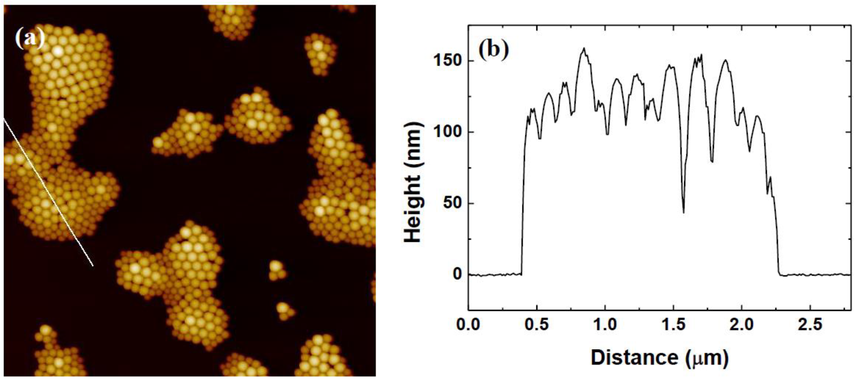
3.1. Variation of Colloidal Concentration (Program A)

Results: For the variation in colloidal concentration, we started with the lowest concentration of 5 g/L. Figure 1 shows the topography image of the spin-coated sample displaying individual islands of colloidal formations with well-ordered and close-packed arrangements seen throughout all structures. For a number of clusters, the nanocolloids have arranged in a size-dependent manner, with larger nanocolloids situated at the centre surrounded by smaller nanocolloids. Other clusters have a less size-correlated structure with various nanocolloid sizes throughout the cluster.
Height profiling of the clusters shows a variation in nanocolloid height between approximately 120 to 160 nm, which is within reasonable agreement with the expected spread of nanocolloid diameters.
In Figure 2, the colloidal concentration was increased to 10 g/L, and it is observed that the nanocolloid particles have begun to structure in bigger islands of well-defined order, with the larger particles surrounded by increasingly smaller particles in a polydisperse configuration. While the close packing of colloidal particles is associated with a hexagonal formation, the polydisperse nature of the nanocolloid particles has generated a variety of different packing formations.
With an increase in the colloidal concentration to 15 g/L, we start to observe large monolayer structures of the colloidal particles, as seen in Figure 3. In particular, Figure 3b shows that the larger particles engulfed in the monolayer films exhibit high levels of order, with the surrounding smaller particle more prone to polycrystalline and amorphous structuring.
In Figure 4, at a colloidal concentration of 20 g/L, it is observed that the size-dependent ordering of the nanocolloidal particles is still in effect, with larger well-ordered particles surrounded by smaller particles with varying degrees of close-packed structuring.
At a colloidal concentration of 25 g/L, the images reveal the beginning of a formation of a continuous film across the surface of the substrate, with only minor gaps appearing in the film, as seen in Figure 5. A height profile confirms that the colloidal film is a monolayer and that protruding nanocolloid particles are still within the upper region of the colloidal diameter CV. A 2D-FFT of the film structure reveals that the nanocolloid particles are configured in an amorphous configuration. While they lack the well-ordered structure of the lower concentrations, the 25 g/L colloidal concentration samples still exhibit a characteristic spacing of 140 nm, which is approximately the median nanocolloid particle diameter.
Finally, at a nanocolloid particle concentration of 50 g/L, the film structuring has become noticeably less ordered, as seen in Figure 6. A 2D-FFT confirms that the characteristic length has increased to 170 nm, which suggests a non-close-packed ordering. The topography image clearly shows the existence of small spaces between particles that were not present in previous samples.
Discussion: At low concentrations, the nanocolloid particles assembled onto the substrate into isolated clusters and grew in size with increasing concentration until forming monolayer films. The majority of the lower colloidal concentration samples contained formations of particle configurations that have larger particles in highly ordered structures surrounded by smaller particles that exhibit a mixture of polycrystalline and amorphous structuring. Such formations have been observed in other systems where polydisperse or binary suspensions of colloidal particles have been allowed to self-assemble into monolayer films. Such structuring is often referred to as “Apollonian” or size-dependent packing [61,62]. This behaviour is attributed to the polydispersity of the colloidal suspensions and the effects of capillary forces during the fourth stage of the spin-coating process, where the liquid film is sufficiently thin to induce lateral capillary forces between neighbouring particles. From capillary theory [63], it is clear that the lateral capillary force occurs due to the partial immersion of neighbouring particles forming a meniscus that induces an attractive force. As such, the largest particles will be the first to experience such an attractive force. The film thickness at this point will be larger than the diameter of smaller particles, so their mobility will allow for the reconfiguration of the particles in the thin film, with larger particles being drawn together, forcing the smaller particles to the extremities. As the liquid film thins, it creates an ordering mechanism which effectively sorts the particles by size. The effective capillary force, being a function of liquid height, causes nanocolloid particles to come under the influence of attractive lateral capillary forces sequentially by size. This phenomenon is most clearly observed with the lower concentration samples where the reduced particle density allows for higher freedom of particle movement on the substrate due to the increased volume of liquid between particles. Thus, nanocolloid particles are able to rearrange more easily, facilitating more size-dependent ordering. Comparing Figure 3b with Figure 5a, it can be seen that at a concentration of 15 g/L, the largest particles have formed patches of highly ordered structures, while at a concentration of 25 g/L, the largest particles are less ordered, exhibiting only smaller clusters of close packing. The 25 and 50 g/L samples show a distinct lack of size-dependent ordered crystals; indeed, the 50 g/L did not display any observable order in its film structuring. This behaviour may be due to the adsorption density reaching a jamming limit on the surface of the mica substrate. Above this jamming limit, the nanocolloidal particles restricted in their lateral mobility, being able to approach neighbouring particles under the influence of lateral capillary forces but unable to reorganise their ordering.

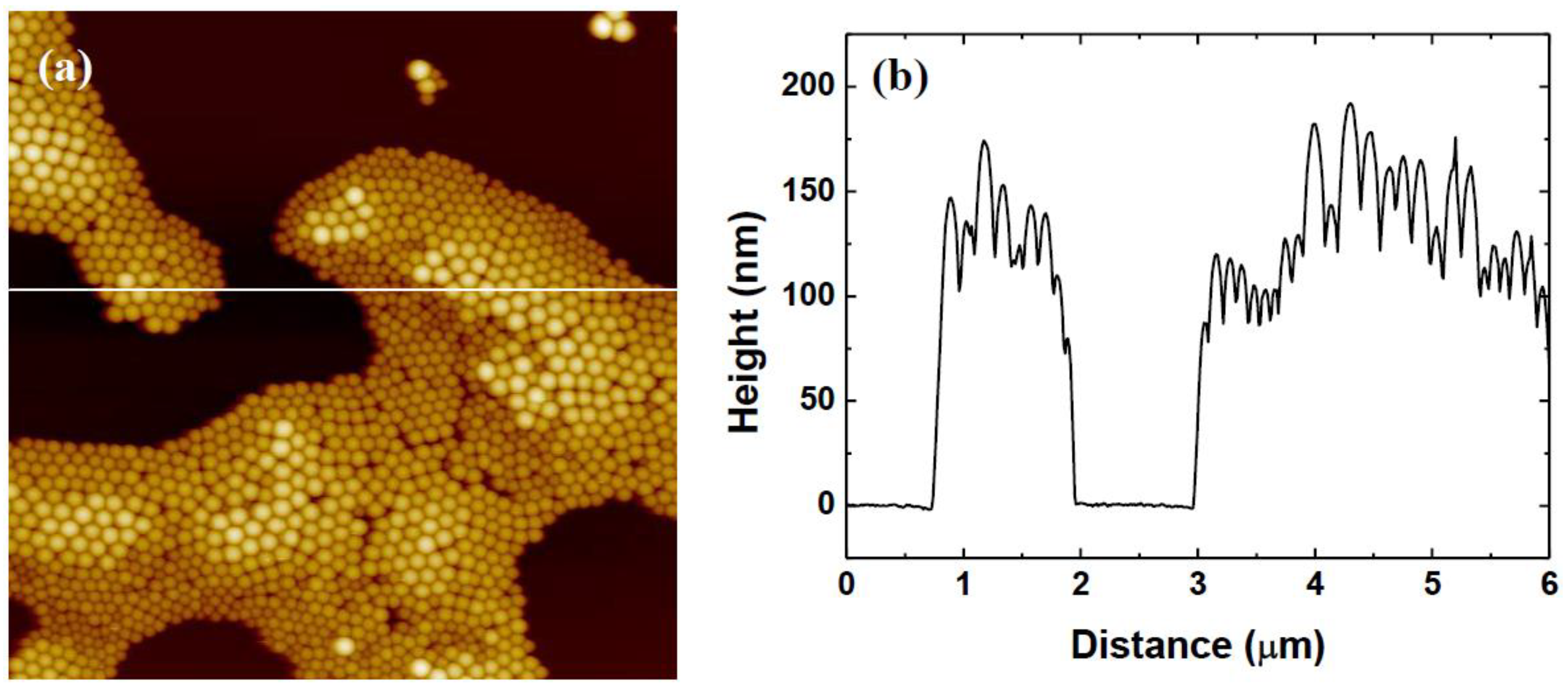
3.2. Variation of Rotational Acceleration (Program B)

Results: For investigations into the effects of increasing rotational acceleration, the 50 g/L colloidal suspension was used in order to ensure that total coverage of the mica substrate is achieved.
Figure 7 shows the film structure for an acceleration of 200 rpm/s. The topography image shows patches of highly ordered nanocolloid particles interspersed with dense amorphous structuring of the surrounding particles. A 2D-FFT of the topography shows a distinct ring indicating a characteristic spacing between particles of approximately 130 nm.
Figure 8 shows the film structure for an acceleration of 400 rpm/s. The topography image shows similar patches of highly ordered nanocolloid particles, although not as prevalent as that of the 200 rpm/s sample. The 2D-FFT reveals the existence of a characteristic spacing between the particles, but the characteristic spacing is increased slightly to 138 nm.
Figure 9 shows a similar trend in behaviour with a reduction in the appearance of crystalline areas of the topography with increasing acceleration. At 600 rpm/s, the characteristic spacing observed on the 2D-FFT has further increased to 140 nm.
Figure 10, representing a rotational acceleration of 800 rpm/s, shows the first large-scale evidence of large gaps appearing between nanocolloid particles in the film, approximately 60–80 nm in size. Previous to this, the observed film structure showed a predominantly continuous formation. These gaps are observed to become more widespread at a rotational acceleration of 1000 rpm/s, shown in Figure 11. The corresponding 2D-FFT images confirm that the characteristic spacing of the particles has increased measurably at these accelerations.
Table 1 gives an overview of the calculated characteristic nanocolloid particle spacing as a function of rotational acceleration, showing a distinct change in the characteristic spacing of the particles between 600 and 800 rpm/s and suggesting a change in the system behaviour.
Discussion: With variation in the rotational acceleration of the substrate during the spin-coating program, the average particle distance, calculated using the radially averaged 2D-FFT profiles, was observed to increase with increasing acceleration. It is considered that with increasing acceleration, the time to reach the target speed is reduced (step 2 of the generalised spin-coating process), which corresponds to an increased rate of change of the shear force, which is responsible for the spreading of the colloidal suspension. The effect of acceleration is of paramount importance as it is responsible for the thinning of the colloidal suspension film and the subsequent capillary self-assembly. At high rotational accelerations, the bulk of the colloidal suspension on the sample substrate is expelled relatively early in the spin-coating program, leaving a relatively thin layer of colloidal suspension behind. This thinner film results in reduced particle mobility, so an even distribution of the particles across the surface via shear forces is not achieved. The subsequent lateral capillary force will be less effective in close packing the particles due to the dependence of the capillary force magnitude on the interparticle separation [64]. This explains why gaps are observed in the higher acceleration samples, as these are generated by the uneven spacing of particles, leading to uneven lateral capillary forces between neighbouring particles. Conversely, at lower accelerations, the liquid surface tension at the edge of the sample has not been overcome by the centrifugal force at an early stage, allowing for the existence of a thicker liquid film in which the particles can form a monolayer structure via shear forces, thus facilitating capillary forces during the drying stage, leading to highly ordered structuring of the nanocolloidal particles.
It was also found that there was a noticeable increase in the characteristic spacing at 600 rpm/s, suggesting a change in behaviour in the distribution of the nanocolloid particles on the surface. Rehg et al. [65] have noted that at sufficiently high accelerations, the coated film may reach its final thickness while the substrate is still accelerating while at low acceleration rates, the effect of different acceleration protocols is negligible since the time required for radial outflow to cease exceeds the time required for the substrate to reach its final angular velocity. It may be the case, therefore, that with accelerations greater than 600 rpm/s, the system enters a regime where the colloidal suspension film has reached its maximum thickness before maximum rotational speed has been achieved. This could result in a poor dispersal of the nanocolloidal particles at the substrate interface (due to the low rotational speed), resulting in compromised lateral capillary forces and, thus, less densely packed structures.

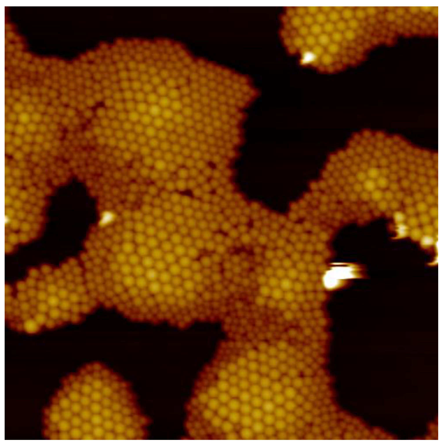
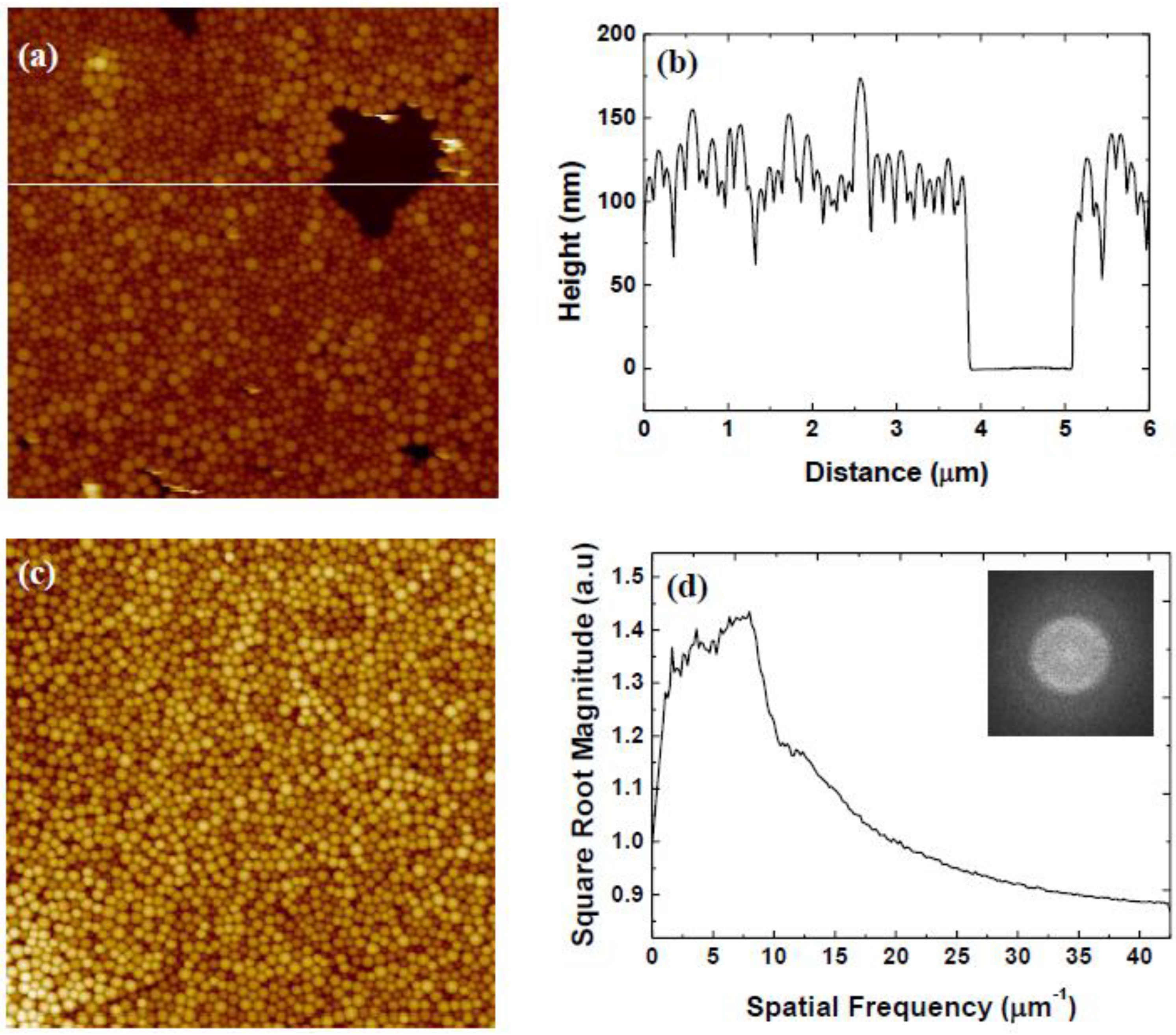
3.3. Variation of Rotational Speed (Program C)

Results: For investigations into the effects of increasing rotational speed, the 50 g/L colloidal suspension was also used in order to ensure that total coverage of the mica substrate is achieved.
In Figure 12, it can be observed that for a rotational speed of 200 rpm, the nanocolloid silica particles have formed into a monolayer that exhibits close packing of the nanocolloidal particles, as seen in the zoomed section. The monolayer film did exhibit some exposed patches of substrate, but the majority of the sample was homogeneous.
For a rotational speed of 400 rpm, Figure 13, the nanocolloidal particles have become increasingly ordered in their configuration, with the zoomed section showing a high degree of polycrystalline structuring of the nanocolloid particles and a reduction in the appearance of gaps between neighbouring particles.
With an increase of the rotational speed to 600 rpm, a large-scale crystallisation of the nanocolloid silica particles across the surface of the substrate was observed (Figure 14a). This particular image was chosen as it has some small voids in the film that allow us to take the height profiles of the film. It should be noted that this is not representative of the majority of the sample area. The highly ordered structures are of a monolayer thickness, as indicated by the height profile in Figure 14b. A smaller topography scan (Figure 14c) illustrates the hexagonal close-packed nature of the film. A multitude of grain boundaries across the surface of the substrate with various crystal orientations was observed. 2D-FFT measurements (Figure 14d) of the topography show a distinctive six-point FFT corresponding to the hexagonal packing of the nanocolloidal particles and a crystal lattice constant of 130 nm.
Figure 15 gives an overview of the topography images for rotational speeds from 800 to 8000 rpm. It can be seen that the previous large-scale crystalline structuring of the silica nanocolloids has given way to a colloidal film of reduced order. The 800 rpm sample (Figure 15a) shows numerous small patches of polycrystalline and amorphous formations similar to that found in the 400 rpm sample. Similar structuring is observed in the 1000 rpm samples, but at 2000 rpm (Figure 15c), the occurrences of well-ordered regions of particles have been severely diminished. By 6000 rpm (Figure 15e), gaps appeared between neighbouring particles that became exacerbated with increasing rotational speed, as seen in the 8000 rpm sample (Figure 15f), along with a total loss of ordered structuring amongst the nanocolloid particles.
Further analysis and discussion: It was found that the level of order in the structuring of the nanocolloid particles varied with rotational speed. Radial distribution function analysis was used to quantitatively examine this level of order and the packing density [66,67]. A radial distribution function represents the probability of finding two particles separated by a distance of r. It is generated by considering each particle, measuring the distance to every other particle and then counting the number (n) of particles a distance r to r + dr from that particle, dn(r, r + dr), with the denominator representing the area (a) of the shell, da(r, r + dr). This process is repeated for all particles until an average value is determined, which is then normalised by dividing by the average particle number density 〈ρn〉 shown in Equation (1). The resultant data is normalised again by setting the asymptotic value to equal one [66,67].
g ( r ) = 1 ρ n d n ( r ,   r + d r ) d a ( r ,   r + d r )
Radial distribution analysis of several topography images revealed a selection of different particle behaviours for the rotational speeds used. Figure 16 shows the radial distribution analysis results for the 200, 600, 1000, and 8000 rpm samples. It should be noted that the 600 rpm has several distinct peaks indicating the presence of the highly crystalline structure, with reoccurring nearest neighbour distances. Both the 200 rpm and the 1000 rpm samples show a much lower first peak followed by a second and third peak before the correlation approaches one. This is indicative of a liquid-like structure where ordering is much more localised. Finally, it can be seen that the 8000 rpm graph has a low first peak followed by values that rapidly approach a plateau, indicating a low correlation and thus suggesting a gaseous colloidal phase lacking any real structuring.
This suggests that the structuring of the nanocolloid particles goes through a transition of moderate order at low rotational speed to high order at a rotational speed of 600 rpm, and subsequently, the order again diminishes with increasing rotational speed.
The spin-coating modelling work of Emslie et al. [68] and Meyerhofer [69] provides relationships between the rotational speed and film thickness when the liquid film is in a stable condition where centrifugal and viscous forces are just in balance. In particular, Meyerhofer has shown that the relationship between the final liquid film thickness hf can be estimated by Equation (2) [69]:
h f = c 0 e 2 1 c 0 K 1 3
where c 0 is the initial solids concentration in the solution, e is the evaporation rate, and K is a constant defined as K = ρω2/(3η) where ρ is the fluid density, ω is the rotational speed and η is the fluid viscosity. The evaporation rate should be constant over the entire substrate and depends on the rotation rate according to e = C ω , where the proportionality constant, C, must be determined for the specific experimental conditions. From this, the dependence of hf on ω can be clearly seen. This film thickness will also dictate the magnitude of the lateral capillary force due to the dependence of the force on the meniscus height. As found in the present study, there is an optimum rotational speed for a given system to produce highly structured configurations. At low rotational speeds, where the film has a more amorphous structuring, the lower shear forces have led to a dense distribution of the nanocolloid particles across the surface of the substrate. As the film will be much thicker than the particle diameter, extended periods of evaporation must occur before the establishment of lateral capillary forces. Subsequently, the capillary self-assembly occurs relatively late in the spin-coating program, leading to more amorphous structuring of the particles. At 600 rpm, an equilibrium has been reached where the rotational speed has induced both sufficient shear forces to spread the particles in a monolayer distribution and form a liquid film thin enough to establish sufficiently strong lateral capillary forces so that close-packed formations are created during the program time frame. At rotational speeds > 600 rpm, the liquid film becomes increasingly thinner, limiting the establishment of effective lateral capillary forces. It is also suggested that at very high rotational speeds, the imposed shear stress may also contribute to the disordering of the nanocolloid particle structuring by causing any adsorbed particles to detach, limiting nucleation sites for the establishment of lateral capillary forces and suppressing effective capillary self-assembly of the nanocolloidal particles.

4. Conclusions

The effects of changes in the colloidal concentration, the rotational acceleration, and the rotational speed on the structuring of 150 nm diameter nanocolloidal silica particles were investigated. The interplay between these parameters allowed for the production of large-scale, highly crystalline monolayer formations of nanocolloid silica particles on mica.
Changes in the colloidal concentration had a marked effect on the configuration of the nanocolloid particles on the substrate, a phenomenon that was emphasised by the polydispersity of our samples. It was shown that size-dependent ordering occurred, where the largest particles formed highly ordered structures that were surrounded by increasingly smaller particles configured into polycrystalline or amorphous structures. This was due to the effective capillary force being a function of liquid height, causing nanocolloid particles to come under the influence of attractive lateral capillary forces sequentially by size. At high concentrations (>25 g/L), this phenomenon was found to be suppressed by the surface particle density, and increasingly amorphous structuring occurred.
With increases in the rotational acceleration, 2D-FFT of the topography and radially averaged profiles revealed that the interparticle spacing increased with increasing acceleration, from close-packed structuring at low accelerations to increasingly spaced packing at high acceleration (>800 rpm/s). This observation was attributed to the effects of liquid shedding, where increased acceleration rates caused rapid shedding of the bulk liquid. Reduced liquid content on the surface resulted in diminished attractive lateral capillary forces and thus reduced close-packed ordering of the nanocolloidal particle structure.
The rotational speed controlled the “crystallinity” of the samples; there is an optimum rotational speed for the experimental parameters used. Radial distribution function analysis was utilised to quantitatively measure the level of order observed in the samples. It was found that at low rotational speed, a disordered structure was formed due to poor distribution of the nanocolloidal particles and delayed establishment of capillary forces, and conversely, at high rotational speed, the excessively thin film limited the magnitude of the lateral capillary force between particles and excessive shear stress triggered the erosion of any crystalline structuring to amorphous configurations. In other words, slower than optimal speeds resulted in a poor distribution of the nanocolloidal particles on the substrate from lack of sufficient shear forces prior to lateral capillary self-assembly; higher than optimal speeds resulted in excessively thin liquid films limiting the effectiveness of the capillary forces, while the increased shear forces eroded any structuring present, resulting in an increasingly colloidal amorphous structure.
This study demonstrates that nanocolloid particles as small as 150 nm can form large scale well-ordered colloidal monolayers provided that the spin-coating parameters are fine-tuned; this work can pave the way for the formation of surface nanotemplates and nanopatterns for advanced chemical sensors, biosensors, optoelectronic devices, superhydrophobic surfaces, and drug/gene delivery systems.

Author Contributions

Conceptualisation, V.K. and J.W.; methodology, V.K. and J.W.; software, J.W.; validation, J.W. and V.K.; formal analysis, J.W.; investigation, J.W.; resources, V.K.; data curation, J.W.; writing—original draft preparation, J.W.; writing—review and editing, J.W. and V.K.; visualisation, J.W.; supervision, V.K.; project administration, V.K.; funding acquisition, J.W. and V.K. All authors have read and agreed to the published version of the manuscript.

Funding

This research was funded by EPSRC, EP/P500206/1, DTA—University of Edinburgh.

Institutional Review Board Statement

Not applicable.

Informed Consent Statement

Not applicable.

Data Availability Statement

Data are available upon request.

Acknowledgments

J.W. acknowledges financial support from EPSRC (DTA—University of Edinburgh). For the purpose of open access, the author has applied a Creative Commons Attribution (CC BY) licence to any Author Accepted Manuscript version arising from this submission.

Conflicts of Interest

The authors declare that they have no conflict of interest.

References

  1. Sharma, E.; Rathi, R.; Misharwal, J.; Sinhmar, B.; Kumari, S.; Dalal, J.; Kumar, A. Evolution in Lithography Techniques: Microlithography to Nanolithography. Nanomaterials 2022, 12, 2754. [Google Scholar] [CrossRef] [PubMed]
  2. Sebastian, E.M.; Jain, S.K.; Purohit, R.; Dhakad, S.K.; Rana, R.S. Nanolithography and its current advancements. Mater. Today Proc. 2020, 26, 2351–2356. [Google Scholar] [CrossRef]
  3. Yoo, S.T.; Park, K.C. Extreme Ultraviolet Lighting Using Carbon Nanotube-Based Cold Cathode Electron Beam. Nanomaterials 2022, 12, 4134. [Google Scholar] [CrossRef] [PubMed]
  4. Cai, Z.; Li, Z.; Ravaine, S.; He, M.; Song, Y.; Yin, Y.; Zheng, H.; Teng, J.; Zhang, A. From colloidal particles to photonic crystals: Advances in self-assembly and their emerging applications. Chem. Soc. Rev. 2021, 50, 5898–5951. [Google Scholar] [CrossRef]
  5. Li, Z.; Fan, Q.; Yin, Y. Colloidal Self-Assembly Approaches to Smart Nanostructured Materials. Chem. Rev. 2022, 122, 4976–5067. [Google Scholar] [CrossRef]
  6. Dwivedi, M.; Singh, S.L.; Bharadwaj, A.S.; Kishore, V.; Singh, A.V. Self-Assembly of DNA-Grafted Colloids: A Review of Challenges. Micromachines 2022, 13, 1102. [Google Scholar] [CrossRef]
  7. Amadi, E.V.; Venkataraman, A.; Papadopoulos, C. Nanoscale self-assembly: Concepts, applications and challenges. Nanotechnology 2022, 33, 132001. [Google Scholar] [CrossRef]
  8. Koutsos, V.; Walker, J.; Glynos, E. Self-Assembly of Colloidal Nanoparticles on Surfaces: Towards Surface Nanopatterning. In Nanostructured Materials and Their Applications; Logothetidis, S., Ed.; Springer: Berlin/Heidelberg, Germany, 2012; pp. 191–211. [Google Scholar]
  9. Cummins, C.; Lundy, R.; Walsh, J.J.; Ponsinet, V.; Fleury, G.; Morris, M.A. Enabling future nanomanufacturing through block copolymer self-assembly: A review. Nano Today 2020, 35, 100936. [Google Scholar] [CrossRef]
  10. Glynos, E.; Chremos, A.; Camp, P.J.; Koutsos, V. Surface Nanopatterning Using the Self-Assembly of Linear Polymers on Surfaces after Solvent Evaporation. Nanomanuf. Metrol. 2022, 5, 297–309. [Google Scholar] [CrossRef]
  11. Glynos, E.; Chremos, A.; Petekidis, G.; Camp, P.J.; Koutsos, V. Polymer-like to Soft Colloid-like Behavior of Regular Star Polymers Adsorbed on Surfaces. Macromolecules 2007, 40, 6947–6958. [Google Scholar] [CrossRef]
  12. Kim, J.H.; Jin, H.M.; Yang, G.G.; Han, K.H.; Yun, T.; Shin, J.Y.; Jeong, S.-J.; Kim, S.O. Smart Nanostructured Materials based on Self-Assembly of Block Copolymers. Adv. Funct. Mater. 2020, 30, 1902049. [Google Scholar] [CrossRef]
  13. Kulkarni, A.A.; Doerk, G.S. Thin film block copolymer self-assembly for nanophotonics. Nanotechnology 2022, 33, 292001. [Google Scholar] [CrossRef] [PubMed]
  14. van Dommelen, R.; Fanzio, P.; Sasso, L. Surface self-assembly of colloidal crystals for micro- and nano-patterning. Adv. Colloid Interface Sci. 2018, 251, 97–114. [Google Scholar] [CrossRef] [PubMed]
  15. Hulteen, J.C.; Van Duyne, R.P. Nanosphere lithography: A materials general fabrication process for periodic particle array surfaces. J. Vac. Sci. Technol. A 1995, 13, 1553–1558. [Google Scholar] [CrossRef]
  16. Mouele, E.S.M.; Ngqoloda, S.; Pescetelli, S.; Di Carlo, A.; Dinu, M.; Vladescu, A.; Parau, A.C.; Agresti, A.; Braic, M.; Arendse, C.J.; et al. Spin Coating Immobilisation of C-N-TiO2 Co-Doped Nano Catalyst on Glass and Application for Photocatalysis or as Electron Transporting Layer for Perovskite Solar Cells. Coatings 2020, 10, 1029. [Google Scholar] [CrossRef]
  17. Faraco, T.A.; Yoshioka, N.A.; Sábio, R.M.; Barud, H.d.S.; Maciel, I.O.; Quirino, W.G.; Fragneaud, B.; Aguiar, A.M.d.; Ribeiro, S.J.L.; Cremona, M.; et al. Monolayer of silica nanospheres assembled onto ITO-coated glass substrates by spin-coating. Nanotechnology 2021, 32, 205603. [Google Scholar] [CrossRef]
  18. Pliatsikas, N.; Kalfagiannis, N.; Arvanitidis, J.; Christofilos, D.; Koutsogeorgis, D.C.; Kagkoura, A.; Sefiane, K.; Koutsos, V.; Patsalas, P. Edge-engineered self-assembled hierarchical plasmonic SERS templates. Appl. Surf. Sci. Adv. 2021, 6, 100186. [Google Scholar] [CrossRef]
  19. Yadav, A.; Gerislioglu, B.; Ahmadivand, A.; Kaushik, A.; Cheng, G.J.; Ouyang, Z.; Wang, Q.; Yadav, V.S.; Mishra, Y.K.; Wu, Y.; et al. Controlled self-assembly of plasmon-based photonic nanocrystals for high performance photonic technologies. Nano Today 2021, 37, 101072. [Google Scholar] [CrossRef]
  20. Mayer, M.; Schnepf, M.J.; König, T.A.F.; Fery, A. Colloidal Self-Assembly Concepts for Plasmonic Metasurfaces. Adv. Opt. Mater. 2019, 7, 1800564. [Google Scholar] [CrossRef]
  21. Oliveira, R.D.; Mouquinho, A.; Centeno, P.; Alexandre, M.; Haque, S.; Martins, R.; Fortunato, E.; Águas, H.; Mendes, M.J. Colloidal Lithography for Photovoltaics: An Attractive Route for Light Management. Nanomaterials 2021, 11, 1665. [Google Scholar] [CrossRef]
  22. Bolshakov, E.S.; Schemelev, I.S.; Ivanov, A.V.; Kozlov, A.A. Photonic Crystals and Their Analogues as Tools for Chemical Analysis. J. Anal. Chem. 2022, 77, 1215–1235. [Google Scholar] [CrossRef]
  23. Wan, Y.-Z.; Qian, W. From Self-Assembly of Colloidal Crystals toward Ordered Porous Layer Interferometry. Biosensors 2023, 13, 730. [Google Scholar] [CrossRef]
  24. Wang, Y.; Zhao, W.; Han, L.; Tam, K.C. Superhydrophobic surfaces from sustainable colloidal systems. Curr. Opin. Colloid Interface Sci. 2022, 57, 101534. [Google Scholar] [CrossRef]
  25. Utsav; Khanna, S.; Paneliya, S.; Makani, N.H.; Mukhopadhyay, I.; Banerjee, R. Controlled restructuring of bidisperse silica nanospheres for size-selective nanowire growth. Mater. Chem. Phys. 2021, 273, 125063. [Google Scholar] [CrossRef]
  26. Xu, X.; Hou, S.; Wattanatorn, N.; Wang, F.; Yang, Q.; Zhao, C.; Yu, X.; Tseng, H.-R.; Jonas, S.J.; Weiss, P.S. Precision-Guided Nanospears for Targeted and High-Throughput Intracellular Gene Delivery. ACS Nano 2018, 12, 4503–4511. [Google Scholar] [CrossRef]
  27. Yu, J.; Lee, C.H.; Kan, C.-W.; Jin, S. Fabrication of Structural-Coloured Carbon Fabrics by Thermal Assisted Gravity Sedimentation Method. Nanomaterials 2020, 10, 1133. [Google Scholar] [CrossRef]
  28. Lu, Z.; Owens, H. Optimum processing parameters for coating polyester with silica nanoparticles using gravity sedimentation. J. Nanoparticle Res. 2019, 21, 212. [Google Scholar] [CrossRef]
  29. Hung, P.-S.; Liao, C.-H.; Chou, Y.-S.; Wang, G.-R.; Wang, C.-J.; Chung, W.-A.; Wu, P.-W. High throughput fabrication of large-area colloidal crystals via a two-stage electrophoretic deposition method. Electrochim. Acta 2019, 317, 52–60. [Google Scholar] [CrossRef]
  30. Askounis, A.; Sefiane, K.; Koutsos, V.; Shanahan, M.E.R. Structural transitions in a ring stain created at the contact line of evaporating nanosuspension sessile drops. Phys. Rev. E 2013, 87, 012301. [Google Scholar] [CrossRef] [PubMed]
  31. Askounis, A.; Sefiane, K.; Koutsos, V.; Shanahan, M.E.R. The effect of evaporation kinetics on nanoparticle structuring within contact line deposits of volatile drops. Colloids Surf. A Physicochem. Eng. Asp. 2014, 441, 855–866. [Google Scholar] [CrossRef]
  32. Mutch, K.J.; Koutsos, V.; Camp, P.J. Deposition of Magnetic Colloidal Particles on Graphite and Mica Surfaces Driven by Solvent Evaporation. Langmuir 2006, 22, 5611–5616. [Google Scholar] [CrossRef] [PubMed]
  33. Hu, M.; Chujo, S.; Nishikawa, H.; Yamaguchi, Y.; Okubo, T. Spontaneous formation of large-area monolayers of well-ordered nanoparticles via a wet-coating process. J. Nanoparticle Res. 2004, 6, 479–487. [Google Scholar] [CrossRef]
  34. Fang, X.; Zheng, C.; Yin, Z.; Wang, Z.; Wang, J.; Liu, J.; Luo, D.; Liu, Y.J. Hierarchically Ordered Silicon Metastructures from Improved Self-Assembly-Based Nanosphere Lithography. ACS Appl. Mater. Interfaces 2020, 12, 12345–12352. [Google Scholar] [CrossRef] [PubMed]
  35. Zhao, L.; Sidnawi, B.; Fan, J.; Chen, R.; Scully, T.; Dietrich, S.; Gao, W.; Wu, Q.; Li, B. Wafer-Scale Full-Coverage Self-Limiting Assembly of Particles on Flexible Substrates. ACS Appl. Mater. Interfaces 2022, 14, 46095–46102. [Google Scholar] [CrossRef] [PubMed]
  36. Watanabe, S.; Miyahara, M.T. Particulate pattern formation and its morphology control by convective self-assembly. Adv. Powder Technol. 2013, 24, 897–907. [Google Scholar] [CrossRef]
  37. Kim, M.H.; Im, S.H.; Park, O.O. Rapid Fabrication of Two- and Three-Dimensional Colloidal Crystal Films via Confined Convective Assembly. Adv. Funct. Mater. 2005, 15, 1329–1335. [Google Scholar] [CrossRef]
  38. Sun, J.; Tang, C.-j.; Zhan, P.; Han, Z.-l.; Cao, Z.-S.; Wang, Z.-L. Fabrication of Centimeter-Sized Single-Domain Two-Dimensional Colloidal Crystals in a Wedge-Shaped Cell under Capillary Forces. Langmuir 2010, 26, 7859–7864. [Google Scholar] [CrossRef]
  39. Bayat, F.; Chaghamirzaei, P.; Nikniazi, A.; Ahmadi-Kandjani, S.; Rashidi, M.-R.; Tajalli, H. Optimizing the concentration of colloidal suspensions in convective assembly of centimeter-sized uniform monolayer colloidal crystals. Appl. Surf. Sci. 2018, 434, 898–904. [Google Scholar] [CrossRef]
  40. Li, J.; Han, Y. Optical Intensity Gradient by Colloidal Photonic Crystals with a Graded Thickness Distribution. Langmuir 2006, 22, 1885–1890. [Google Scholar] [CrossRef]
  41. Hsu, C.-M.; Connor, S.T.; Tang, M.X.; Cui, Y. Wafer-scale silicon nanopillars and nanocones by Langmuir–Blodgett assembly and etching. Appl. Phys. Lett. 2008, 93, 133109. [Google Scholar] [CrossRef]
  42. Gu, P.; Cai, X.; Chen, S.; Zhang, Z.; Chen, J.; Du, W.; Tang, C.; Yan, Z.; Chen, Z. Rapid fabrication of high-quality bare silica monolayer and multilayers at the water/air interface. Results Phys. 2020, 19, 103404. [Google Scholar] [CrossRef]
  43. Walker, J.; Schofield, A.B.; Koutsos, V. Nanostructures and Thin Films of Poly(Ethylene Glycol)-Based Surfactants and Polystyrene Nanocolloid Particles on Mica: An Atomic Force Microscopy Study. Coatings 2023, 13, 1187. [Google Scholar] [CrossRef]
  44. García Núñez, C.; Navaraj, W.T.; Liu, F.; Shakthivel, D.; Dahiya, R. Large-Area Self-Assembly of Silica Microspheres/Nanospheres by Temperature-Assisted Dip-Coating. ACS Appl. Mater. Interfaces 2018, 10, 3058–3068. [Google Scholar] [CrossRef]
  45. Osipov, A.A.; Gagaeva, A.E.; Speshilova, A.B.; Endiiarova, E.V.; Bespalova, P.G.; Osipov, A.A.; Belyanov, I.A.; Tyurikov, K.S.; Tyurikova, I.A.; Alexandrov, S.E. Development of controlled nanosphere lithography technology. Sci. Rep. 2023, 13, 3350. [Google Scholar] [CrossRef]
  46. Lan, N.T.T.; Hoang, C.M. Fabrication and Characteristics of Silica Nanoparticle Monolayer Assembled by Spin Coating. VNU J. Sci. Math. Phys. 2022, 38, 111–118. [Google Scholar] [CrossRef]
  47. Razaulla, T.; Bekeris, M.; Feng, H.; Beeman, M.; Nze, U.; Warren, R. Multiple Linear Regression Modeling of Nanosphere Self-Assembly via Spin Coating. Langmuir 2021, 37, 12419–12428. [Google Scholar] [CrossRef] [PubMed]
  48. Noppakuadrittidej, P.; Tonsomboon, K.; Ummartyotin, S. Importance of solvent singularity on the formation of highly uniform hexagonal close packed (HCP) colloidal monolayers during spin coating. Colloid Interface Sci. Commun. 2019, 30, 100177. [Google Scholar] [CrossRef]
  49. Khanna, S.; Utsav; Chaliyawala, H.; Paneliya, S.; Roy, D.; Mukhopadhyay, K.; Banerjee, R.; Mukhopadhyay, I. Systematic investigation of close-packed silica nanospheres monolayer under sintering conditions. J. Eur. Ceram. Soc. 2019, 39, 1411–1419. [Google Scholar] [CrossRef]
  50. Khanna, S.; Utsav; Marathey, P.; Chaliyawala, H.; Rajaram, N.; Roy, D.; Banerjee, R.; Mukhopadhyay, I. Fabrication of long-ranged close-packed monolayer of silica nanospheres by spin coating. Colloids Surf. A Physicochem. Eng. Asp. 2018, 553, 520–527. [Google Scholar] [CrossRef]
  51. Chandramohan, A.; Sibirev, N.V.; Dubrovskii, V.G.; Petty, M.C.; Gallant, A.J.; Zeze, D.A. Model for large-area monolayer coverage of polystyrene nanospheres by spin coating. Sci. Rep. 2017, 7, 40888. [Google Scholar] [CrossRef]
  52. Choi, J.-Y.; Alford, T.L.; Honsberg, C.B. Solvent-Controlled Spin-Coating Method for Large-Scale Area Deposition of Two-Dimensional Silica Nanosphere Assembled Layers. Langmuir 2014, 30, 5732–5738. [Google Scholar] [CrossRef] [PubMed]
  53. Chen, J.; Dong, P.; Di, D.; Wang, C.; Wang, H.; Wang, J.; Wu, X. Controllable fabrication of 2D colloidal-crystal films with polystyrene nanospheres of various diameters by spin-coating. Appl. Surf. Sci. 2013, 270, 6–15. [Google Scholar] [CrossRef]
  54. Ogi, T.; Modesto-Lopez, L.B.; Iskandar, F.; Okuyama, K. Fabrication of a large area monolayer of silica particles on a sapphire substrate by a spin coating method. Colloids Surf. A Physicochem. Eng. Asp. 2007, 297, 71–78. [Google Scholar] [CrossRef]
  55. Colson, P.; Cloots, R.; Henrist, C. Experimental Design Applied to Spin Coating of 2D Colloidal Crystal Masks: A Relevant Method? Langmuir 2011, 27, 12800–12806. [Google Scholar] [CrossRef]
  56. Jurewicz, I.; King, A.A.K.; Worajittiphon, P.; Asanithi, P.; Brunner, E.W.; Sear, R.P.; Hosea, T.J.C.; Keddie, J.L.; Dalton, A.B. Colloid-Assisted Self-Assembly of Robust, Three-Dimensional Networks of Carbon Nanotubes over Large Areas. Macromol. Rapid Commun. 2010, 31, 609–615. [Google Scholar] [CrossRef] [PubMed]
  57. Qi, G.; Yang, Y.; Yan, H.; Guan, L.; Li, Y.; Qiu, X.; Wang, C. Quantifying Surface Charge Density by Using an Electric Force Microscope with a Referential Structure. J. Phys. Chem. C 2009, 113, 204–207. [Google Scholar] [CrossRef]
  58. Israelachvili, J.N.; Alcantar, N.A.; Maeda, N.; Mates, T.E.; Ruths, M. Preparing Contamination-free Mica Substrates for Surface Characterization, Force Measurements, and Imaging. Langmuir 2004, 20, 3616–3622. [Google Scholar] [CrossRef]
  59. Bergström, L.; Bostedt, E. Surface chemistry of silicon nitride powders: Electrokinetic behaviour and ESCA studies. Colloids Surf. 1990, 49, 183–197. [Google Scholar] [CrossRef]
  60. Johnson, C.A.; Lenhoff, A.M. Adsorption of Charged Latex Particles on Mica Studied by Atomic Force Microscopy. J. Colloid Interface Sci. 1996, 179, 587–599. [Google Scholar] [CrossRef]
  61. Antonietti, M.; Hartmann, J.; Neese, M.; Seifert, U. Highly Ordered Size-Dispersive Packings of Polydisperse Microgel Spheres. Langmuir 2000, 16, 7634–7639. [Google Scholar] [CrossRef]
  62. Yamaki, M.; Higo, J.; Nagayama, K. Size-Dependent Separation of Colloidal Particles In Two-Dimensional Convective Self-Assembly. Langmuir 1995, 11, 2975–2978. [Google Scholar] [CrossRef]
  63. Kralchevsky, P.A.; Paunov, V.N.; Ivanov, I.B.; Nagayama, K. Capillary meniscus interaction between colloidal particles attached to a liquid—Fluid interface. J. Colloid Interface Sci. 1992, 151, 79–94. [Google Scholar] [CrossRef]
  64. Denkov, N.; Velev, O.; Kralchevski, P.; Ivanov, I.; Yoshimura, H.; Nagayama, K. Mechanism of formation of two-dimensional crystals from latex particles on substrates. Langmuir 1992, 8, 3183–3190. [Google Scholar] [CrossRef]
  65. Rehg, T.J.; Higgins, G. Spin coating of colloidal suspensions. AIChE J. 1992, 38, 489–501. [Google Scholar] [CrossRef]
  66. Smith, B.; Vasut, J.; Hyde, T.; Matthews, L.; Reay, J.; Cook, M.; Schmoke, J. Dusty plasma correlation function experiment. Adv. Space Res. 2004, 34, 2379–2383. [Google Scholar] [CrossRef]
  67. Moon, J.; Park, J.-A.; Lee, S.-J.; Zyung, T. Insight into the Shear-Induced Ordering of Colloidal Particles by a Spin-Coating Method. Jpn. J. Appl. Phys. 2008, 47, 7968–7971. [Google Scholar] [CrossRef]
  68. Emslie, A.G.; Bonner, F.T.; Peck, L.G. Flow of a Viscous Liquid on a Rotating Disk. J. Appl. Phys. 2004, 29, 858–862. [Google Scholar] [CrossRef]
  69. Meyerhofer, D. Characteristics of resist films produced by spinning. J. Appl. Phys. 1978, 49, 3993–3997. [Google Scholar] [CrossRef]
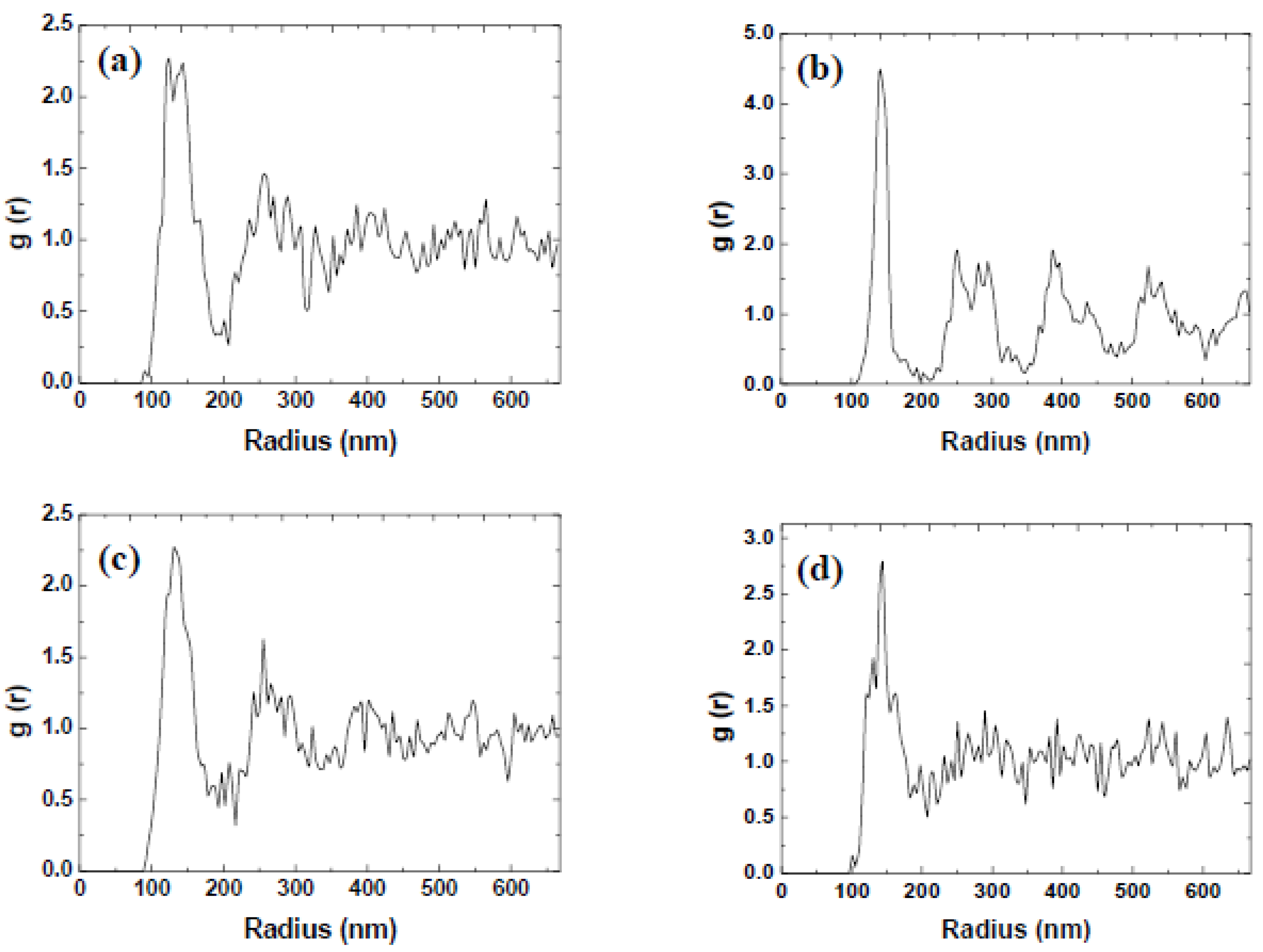
Figure 1. (a) 6 × 6 μm2 topography scan of a colloidal sample prepared using the 5 g/L colloidal suspension and spin-coating program A with (b) height profile corresponding to the white line.
Coatings 13 01488 g001
Figure 2. (a) 6 × 6 μm2 topography scan of a colloidal sample prepared using the 10 g/L colloidal suspension and spin-coating program A with (b) height profile corresponding to the white line.
Coatings 13 01488 g002
Figure 3. (a,b) 6 × 6 μm2 topography scans of a colloidal sample prepared using the 15 g/L colloidal suspension and spin-coating program A; (b) shows some of the finer structure of the film of polydisperse colloidal particles.
Coatings 13 01488 g003
Figure 4. 6 × 6 μm2 topography scan of a colloidal sample prepared using the 20 g/L colloidal suspension and spin-coating program A.
Coatings 13 01488 g004
Figure 5. (a) 6 × 6 μm2 topography scan of a colloidal sample prepared using the 25 g/L colloidal suspension and spin-coating program A with (b) height profile corresponding to the white line showing monolayer structure. (c) 6 × 6 μm2 topography scan of a continuous film with (d) corresponding radially averaged profile of 2D-FFT (inset).
Coatings 13 01488 g005
Figure 6. (a) 6 × 6 μm2 topography scan of a colloidal sample prepared using the 50 g/L colloidal suspension and spin-coating program A with (b) corresponding radially averaged profile of 2D-FFT (inset).
Coatings 13 01488 g006
Figure 7. (a) 14 × 14 μm2 topography scan of a colloidal sample prepared using the 50 g/L colloidal suspension with spin-coating program B with an acceleration of 200 rpm/s with zoom inset. (b) Corresponding radially averaged profile of 2D-FFT (inset) of (a).
Coatings 13 01488 g007
Figure 8. (a) 14 × 14 μm2 topography scan of a colloidal sample prepared using the 50 g/L colloidal suspension with spin-coating program B with an acceleration of 400 rpm/s with zoom inset. (b) Corresponding radially averaged profile of 2D-FFT (inset) of (a).
Coatings 13 01488 g008
Figure 9. (a) 14 × 14 μm2 topography scan of a colloidal sample prepared using the 50 g/L colloidal suspension with spin-coating program B with an acceleration of 600 rpm/s with zoom inset. (b) Corresponding radially averaged profile of 2D-FFT (inset) of (a).
Coatings 13 01488 g009
Figure 10. (a) 14 × 14 μm2 topography scan of a colloidal sample prepared using the 50 g/L colloidal suspension with spin-coating program B with an acceleration of 800 rpm/s with zoom inset. (b) Corresponding radially averaged profile of 2D-FFT (inset) of (a).
Coatings 13 01488 g010
Figure 11. (a) 14 × 14 μm2 topography scan of a colloidal sample prepared using the 50 g/L colloidal suspension with spin-coating program B with an acceleration of 1000 rpm/s with zoom inset. (b) Corresponding radially averaged profile of 2D-FFT (inset) of (a).
Coatings 13 01488 g011
Figure 12. (a) 14 × 14 μm2 topography scan of a colloidal sample prepared using the 50 g/L colloidal suspension with spin-coating program C at a rotational speed of 200 rpm. (b) Corresponding image of the zoomed section marked in (a) shows the structured formation of nanocolloid particles.
Coatings 13 01488 g012
Figure 13. (a) 14 × 14 μm2 topography scan of a colloidal sample prepared using the 50 g/L colloidal suspension with spin-coating program C at a rotational speed of 400 rpm. (b) Corresponding image of the zoomed section marked in (a) shows the structured formation of nanocolloid particles.
Coatings 13 01488 g013
Figure 14. (a) 14 × 14 μm2 topography scan of a colloidal sample prepared using the 50 g/L colloidal suspension with spin-coating program C at a rotational speed of 600 rpm. (b) The height profile of the structured film corresponds to the white line in (a). (c) Zoom showing the hexagonal close-packed structuring of the nanocolloid silica particles with (d) a 2D-FFT (inset) and the corresponding radial average profile with a clear peak of the crystal lattice constant.
Coatings 13 01488 g014
Figure 15. 14 × 14 μm2 topography scans of a colloidal sample prepared using the 50 g/L colloidal suspension with spin-coating program C at a rotational speed of (a) 800 rpm, (b) 1000 rpm, (c) 2000 rpm, (d) 4000 rpm, (e) 6000 rpm, and (f) 8000 rpm.
Coatings 13 01488 g015
Figure 16. Radial distribution functions of the topography scans of samples prepared using spin-coating program C with rotational speeds of (a) 200 rpm, (b) 600 rpm, (c) 1000 rpm, and (d) 8000 rpm.
Coatings 13 01488 g016
Table 1. Comparison of rotational acceleration and the characteristic spacing of the nanocolloid silica particles calculated from the radially averaged 2D-FFT measurements.
Rotational Acceleration (rpm/s)Characteristic Spacing (nm)
200133
400138
600140
800168
1000172
Disclaimer/Publisher’s Note: The statements, opinions and data contained in all publications are solely those of the individual author(s) and contributor(s) and not of MDPI and/or the editor(s). MDPI and/or the editor(s) disclaim responsibility for any injury to people or property resulting from any ideas, methods, instructions or products referred to in the content.

