Article

The Effect of Electroplating Nickel on the Mechanical Properties of Brittle Mg-Based Bulk Metallic Glasses

Hebei Key Laboratory of New Functional Materials, School of Material Science and Engineering, Hebei University of Technology, No. 5340, Xiping Road, Beichen District, Tianjin 300401, China
*
Authors to whom correspondence should be addressed.
These authors contributed equally to this work.
Coatings 2023, 13(9), 1598; https://doi.org/10.3390/coatings13091598
Submission received: 18 August 2023 / Revised: 6 September 2023 / Accepted: 12 September 2023 / Published: 13 September 2023
(This article belongs to the Special Issue Microstructure, Mechanical and Tribological Properties of Alloys)

Abstract

:
Magnesium-based bulk metallic glasses (BMGs) are typical intrinsic brittle lightweight BMG alloys, and their improvement in plasticity has attracted widespread attention in the field of BMGs. We used the electroplating method to modify the surface of Mg59.5Cu22.9Ag11Gd6.6 BMGs and investigated the geometric confinement effect of the Ni coating on the mechanical properties of the BMG. The results show that under the plating conditions of adding 1 g/L nano Al2O3 to the plating solution, adjusting the plating temperature to 50 °C, and plating time to 3 h, a smooth and dense nickel coating with a thickness of about 150 μm can be formed on the surface of the Mg-based BMG. The uniaxial compression tests showed that the average fracture strength of the BMG was increased from 565 MPa to 598 MPa by a 50 μm Ni coating, and the fluctuation range of strength was decreased from 429 MPa to 265 MPa, a reduction of 36%. The Weibull analysis showed that the Weibull modulus m was increased from 4.3 to 4.8 by the coating, and the safety stress was increased from 54 MPa to 235 MPa, indicating that electroplating nickel could improve the reliability of the Mg-based BMG alloy. However, no significant improvement of the compression plasticity was found, which indicated that improving the room temperature plasticity of brittle Mg-based BMG alloys by the geometric confinement of electroplating Ni was limited. The influence of the thickness of the Ni coating on the maximum stress level and stress distribution in the BMG samples was analyzed by ANSYS finite element simulation. It was found that when the thickness of the coating was 30% of the radius of the cylindrical compressed sample, the stress distribution caused by the Ni coating was the most uniform, and the maximum stress level was relatively reduced, which is beneficial for improving the geometric confinement effect. As a result, the Mg-based BMG sample coated with a Ni coating of 150 μm thickness exhibited ~0.3% macroscopic compressive plasticity. This is of great significance for understanding the plastic deformation mechanism of brittle BMGs improved by geometric confinement.

1. Introduction

Bulk metallic glasses (BMGs) generally are single-phase materials with disordered atomic packing structures without traditional defects, such as dislocations and interfaces commonly found in crystalline materials, and their strength is generally higher than corresponding crystalline alloys [1]. However, most of the BMG alloys are considered brittle/quasi-brittle materials due to their poor plasticity [2], which greatly limits their application fields. Therefore, the research on improving the room temperature plasticity of BMG alloys has attracted widespread attention internationally [3]. There are two main toughening strategies of BMG alloys, namely intrinsic toughening and extrinsic toughening [4]. The intrinsic toughening method of BMGs refers to improving plasticity by modulating the composition or controlling the formation conditions of BMG alloys while ensuring the special atomic arrangement structures such as free volume [5,6,7], nanovoids [8,9,10,11], and microscopic chemical/structural heterogeneity [12,13,14]. This method mainly depends on alloying or micro-alloying, which often sacrifices some of the glass forming ability (GFA) and is not suitable for those “particularly brittle” BMG alloy systems, such as Mg-based BMGs [15]. The extrinsic toughening methods include metallic glass matrix composites (MGMCs) [16,17,18,19,20], geometric confinement [21,22], deformation conditions [23,24,25], and so on. Firstly, the toughening of MGMCs depends on the introduction of a crystalline second phase, which usually has excellent ductility, to turn the shear banding behavior of the MG matrix. However, in general, this method partially sacrifices the high strength of BMG alloys due to the low yield strength of the second phase [19]. Secondly, the toughening strategy of the geometric confinement method is to limit the early plastic deformation of BMGs by applying geometric constraints (or surface residual stress) [26], which improves the shear band nucleation and delays the rapid shear band propagation. Thirdly, the toughening strategy of changing the deformation conditions mainly includes a low strain rate, a low aspect ratio, a small sample size, and so on. Although changing the deformation conditions played an important role in understanding the deformation nature of BMGs, they lack sufficient attractiveness for the large-scale engineering applications of BMGs.
It is well-known that the surface of materials often contains different defects, which can become the origin of failure. For BMGs, surface defects also play an important role in the formation of shear bands and crack initiation due to their brittleness. Therefore, surface modification of BMGs has received widespread attention in the BMG field, especially in studies aimed at improving plasticity. In 2006, Zhang et al. conducted surface shot peening on a Zr-based BMG, and significantly improved its compressive plasticity [27]. Their strategy is to introduce surface residual stress and preset nucleation points of shear bands to interfere with the plastic deformation of BMGs. Although there is currently controversy internationally regarding the surface stress state caused by shot peening (compressive or tensile stress) [26,27,28,29,30,31], this surface treatment strategy has produced significant results in many subsequent studies. For example, Lu et al. used the ultrasonic shot peening method to treat the surface of several BMG alloys, achieving good toughening effects [32,33,34]. In 2014, they reported an obvious tensile ductility of ~4% [14], which is rarely found in the surface modification studies of BMGs. Similarly, Chen and Wu et al. used laser surface treatment to effectively improve the compressive plasticity of amorphous alloys [35,36]. However, Raghavan et al. found that, after surface shot peening treatment, crack sources may appear on the surface of BMGs, leading to a degradation of fatigue performances [37]. Essentially, this is due to the fact that shot peening and laser heating surface treatment are a type of damage to the BMG surface, which inevitably promotes the initiation of fatigue cracks.
In addition to the influence of residual stress, surface treatment can also impose geometric confinements on BMGs during deformation, thereby affecting their deformation behavior. The related study first focused on the plastic improvement research of Zr-based BMGs. Yu et al. effectively improved the plasticity of Zr41.2Ti13.8Cu12.5Ni10Be22.5 BMG (Vit 1) by the geometric confinement of wrapped metal Cu sleeves [22]. A strategy derived from this is to use coating preparation technology to chemically modify the surface of BMG alloys. In 2007, Li et al. deposited Ni-15%Fe nanocrystalline coatings on the surface of a Zr58Ni13.6Cu18Al10.4 BMG alloy through traditional electroplating methods, improving its compressive plasticity significantly [38]. Afterward, the electroplating method attracted widespread attention internationally due to its efficient toughening effect and low cost. Ren et al. used electroless Ni-P plating to improve the plasticity of Vit 1 BMG, without obvious sacrifice of the yielding strength [39]. Qiu et al. employed electrodeposited copper coatings on Vit 1 BMG to improve the plasticity, and found that the Cu coatings effectively inhibited the shear band propagation and promoted the shear band nucleation [40]. Choi et al. also used Cu electroplating to improve the plasticity of Zr-based BMGs, and they pointed out that the filling and smoothening effect of the soft Cu coating played an important role in absorbing the elastic deformation energy and in suppressing the crack nucleation [41,42]. Interestingly, Chen et al. prepared a Cu/Ni bilayered coating on the surface of a Zr-based BMG. They used a thin soft Cu layer as a buffer to absorbing the deformation energy, and a strong outer Ni coating for geometric confinement effects [43]. Also, Ren et al. used electrodeposition and chemical plating to prepare a Ni-P/Ni bilayer on Vit 1 BMG, forming an “amorphous-crystalline-amorphous” sandwiched structure to effectively improve the ductility of Zr-based BMG [44]. In these studies, the effectiveness of the coating in the geometric confinement of BMG alloys was considered closely related to the thickness of the coating. When the electroplating Cu coating reaches 160 μm, the Cu coating does not even fracture after the fracture of the BMG alloy [45].
The strategy of using coatings to impose geometric confinements to improve plasticity is also applicable to the BMG systems in addition to Zr-based BMGs. Chen et al. prepared an electroplating Ni coating on a Fe75Mo5P10C8.3B1.7 BMG, significantly improving the plasticity up to 5.0%, which was attributed to the multiple shear banding caused by the geometric limiting effect [46]. Recently, we prepared a relatively thin electroless Ni-based coating (~7 μm), which was approximately 10% of the traditional electroplated Ni coating and showed an excellent toughening effect [47]. We also used electroless plating to prepare a 10 μm thickness Ni-P coating on a typical Ti-based BMG, which significantly improved the plasticity [48]. We found that it was more important for Ti-based BMGs to improve the adhesive bonding strength than to increase the coating thickness. Cao et al. used chemical Ni-P plating to toughen a Ti20Zr20Hf20Be20Cu20 high entropy BMG and successfully increased its plasticity by 3.7 times [49]. So far, research on geometric constraint toughening of BMGs has mainly involved Zr-based, Ti-based, and Fe-based BMG alloys, while other brittle BMG systems, especially brittle Mg-based BMGs, still need to be validated. In addition, it is well-known that the nickel plating layer has a significant improvement in the corrosion resistance of traditional crystalline magnesium alloys [50]. As a member of the BMG family with poor corrosion resistance, it is also worth studying how the corrosion resistance of Mg-based BMG changes after nickel plating treatment.
In this work, we focused on investigating the geometric confinement effect of nickel plating on typical Mg-based BMGs. We used the electroplating method to prepare Ni coatings with different thicknesses on the surface of a typical brittle Mg59.5Cu22.9Ag11Gd6.6 [51,52] BMG round rod. The influence of the Ni coating on the mechanical properties of the BMG was analyzed through quasi-static compression experiments, and the stress characteristics of the coating thickness on the sample during deformation were analyzed through finite element simulation.

2. Materials and Methods

2.1. Preparation of BMG Samples

Raw materials including freshly cut Mg (purity 99.99 wt.%), Cu (99.99 wt.%), Ag (99.9 wt.%), and Gd (99 wt.%) small pieces were ultrasonically cleaned with alcohol for about 15 min. A precision analytical balance (Mettler, ME204E, Columbus, OH, USA) was used to weigh and prepare the raw material mixture according to the atomic ratio of Mg59.5Cu22.9Ag11Gd6.6 [52]. After placing the raw materials in a graphite crucible placed in the heating coil of a vacuum high-frequency melting furnace (Shanghai MTINST, VIMS-1000, Shanghai, China), the furnace cavity was pumped to a vacuum degree of less than −1.0 × 10⁻² Pa through a vacuum pump. After extracting the vacuum, high-purity argon gas was filled in the furnace to a pressure of about 0.5 bar. Afterward, an induction coil was used to melt the mixed raw materials, and the alloy melt was poured into a copper mold to cool and solidify them into the master alloy ingots. The master alloy ingots were cut into appropriate-sized blocks, and the collected small pieces were placed in a quartz tube with a small hole at the bottom with a diameter of approximately 1–2 mm (detailed in the earlier report [53]). Then, the quartz tube was loaded into the injection casting coil, and the master alloy was re-melted using the induction heating method. Argon gas with a pressure of ~0.1 MPa was blown into the upper part of the quartz tube, and the alloy melt was injected into a copper mold with an inner diameter of 1–2 mm and a length of 5–10 cm. The rapid cooling induced by high-purity copper led to the rapid freezing of Mg-Cu-Ag-Gd alloy melt, forming cylindrical rods with a full amorphous structure.

2.2. Electroplating Treatment

Figure 1 shows the flowchart of the electroplating Ni process on the surface of the Mg59.5Cu22.9Ag11Gd6.6 BMG rod. Firstly, the surface of as-cast Mg-Cu-Ag-Gd BMG cylindrical rods was mechanically ground by using #2000 sandpaper to remove surface oxides and casting defects. Secondly, the polished samples were soaked in the acid washing solution (Table 1) for 90 s to increase the surface roughness through slight corrosion, which is helpful to the formation of the close bonding between the coating and the BMG substrate. Thirdly, the washed and dried samples were immersed in the activation solution for 5 min to combine Mg and F ions on the surface of the BMG sample to form a certain fluoride to facilitate the deposition of Zn. Fourthly, the BMG samples after activation were put in a zinc dipping solution for the first Zn dipping treatment, which was kept for 10 min at a constant temperature of 65 °C to pre-plate a Zn layer. Fifthly, the first zinc precipitation samples were rinsed with the zinc removal solution to partially remove the coarse zinc particles, preparing for the secondary zinc dipping. Sixthly, a second activation and zinc dipping treatment were performed using the same solutions, with a soaking time of 5 min, to prepare a thin zinc layer with good coverage as the substrate for nickel plating. At last, for the final electroplating Ni process, nickel sheets with a purity of 99.9% were used as the electroplating anode, and the Mg-based BMG samples with Zn layers were suspended as the cathode and placed in the electroplating solution. The temperature of the plating solution was controlled at 50 °C, and the plating time was 1–3 h to obtain nickel coatings with different thicknesses. The solution components involved in the above process are detailed in Table 1.

2.3. Material Characterization Methods

Optical microscopy (OM, Zeiss, Axio Imager M2m, Jena, Germany) was used to examine the low magnification microstructure of the Ni coatings. The thickness of the coatings was also measured by the Zeiss OM. Scanning electron microscopy (SEM, Hitachi S-4800, Tokyo, Japan) was used to obtain the high magnification microstructure of the coatings. An energy dispersive spectrometer (EDS) equipped with the SEM was used to examine the composition of the coatings. An X-ray diffractometer (XRD, Bruker D8 Advance, Cu Kα radiation, Billerica, MA, USA) was used to characterize the phase structure of the nickel-plated and non-nickel-plated samples, with a scanning speed of 8°/min and a scanning angle range of 10–90°.
A low-speed diamond cutting machine (Kejing, SYJ-150, Shenyang, China) was used to cut the as-cast and as-coated BMG rods into cylindrical compressed samples, with a diameter-to-height ratio of d:h = 1:2. The cut samples were ultrasoundly cleaned with acetone to remove coolant and chips. A universal testing machine (Guanteng, PA200, Changchun, China) was used to test the mechanical properties of the Ni-electroplated BMG and un-plated samples at room temperature in compression, with a strain rate of about 4.0 × 10⁻⁶ s−1.

2.4. Finite Element Simulation Method

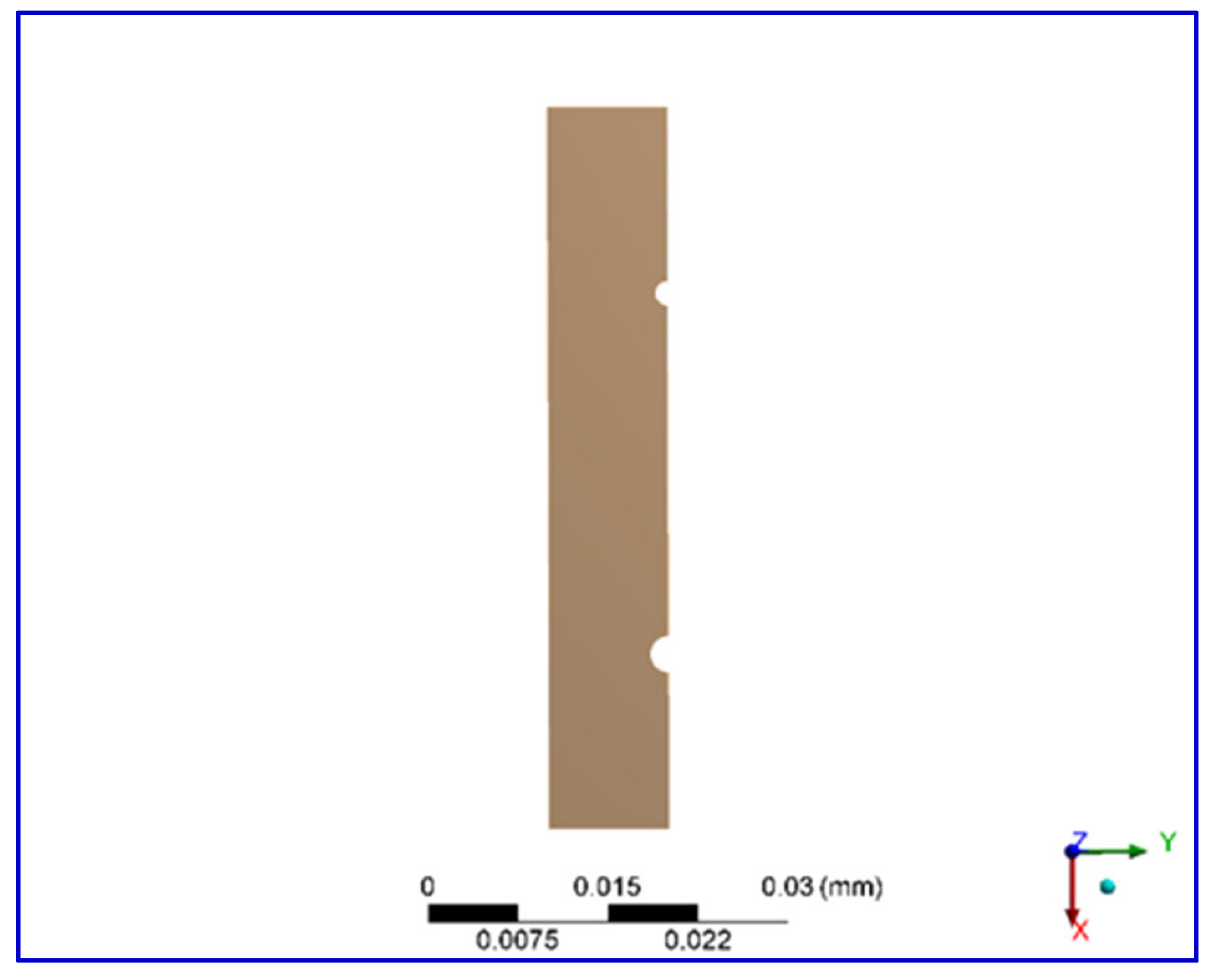
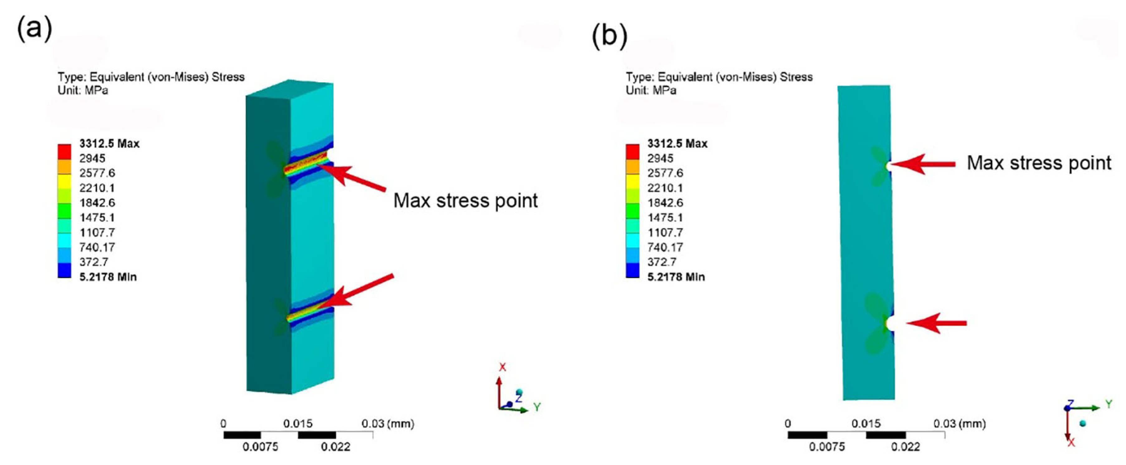
ANSYS Workbench software 14.0 was used to establish a finite element model (FEM) of the Mg-based BMG samples before and after nickel electroplating, and the static stress status of the BMG samples during compression deformation was analyzed. The main material performance parameters of Mg-based BMG were set as Young’s modulus E = 50 GPa and Poisson’s ratio ν = 0.32. The material parameters of the nickel coatings were selected as the default value for pure Ni in the software system. We established a rectangular model with a size of 60 μm × 10 μm × 20 μm. One side of the model was prefabricated with two semi-cylindrical hole defects 30 μm apart, which are 15 μm from the top or the bottom surfaces, with a diameter of 2 μm and 3 μm, respectively, as shown in Figure 2. Afterward, different thicknesses (1 μm, 2 μm, 3 μm, 4 μm, 5 μm, 10 μm, and 20 μm) of the Ni coatings were established on the surface with defects. The grid units of the sample were automatically generated by the software, and the grid size was about 0.5 μm. A compressive stress of 1000 MPa was applied on the upper and lower surfaces of the samples, outputting a stress distribution map after calculation and solution.

3. Results

3.1. Microstructure of the Ni Coating

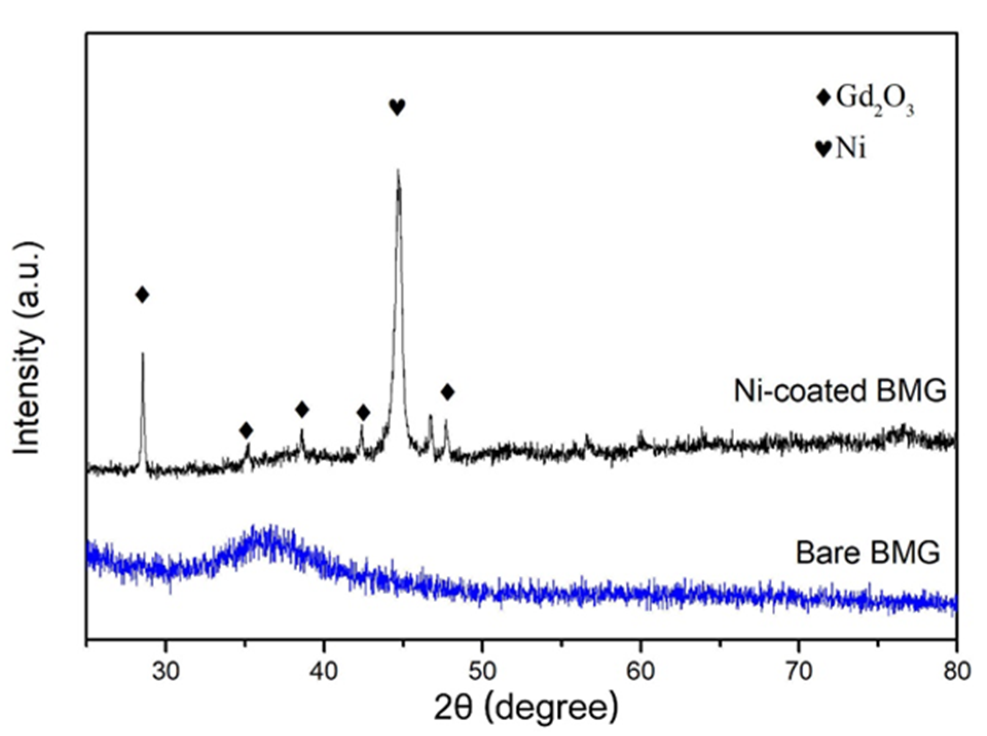
Figure 3 shows the XRD patterns of the Ni-electroplated surface of the Mg-Cu-Ag-Gd BMG sample and the cross-section of the untreated BMG sample. It clearly shows that the XRD pattern of the uncoated BMG sample exhibits typical amorphous characteristics, i.e., no sharp diffraction peaks. The XRD pattern of the Ni-electroplated surface shows some diffraction peaks attributed to Ni and Gd2O3, respectively, and the peaks of Ni are significantly higher than Gd2O3. This indicates that the surface of the Ni-plated sample is mainly composed of Ni crystals, with a smaller amount of Gd2O3 phase. The formation of the Gd2O3 phase can be attributed to the fact that the acidic plating solution has a significant corrosive oxidation effect on the Mg-Cu-Ag-Gd BMG substrate, causing the enrichment of O element on the surface of the BMG. In addition, the element with the highest affinity for oxygen in the Mg-Cu-Ag-Gd BMG alloy is Gd, so the surface of the sample undergoes selective oxidation [54,55,56] of the rare-earth element Gd during the plating process. The oxidation products of Gd are insoluble in water and can easily be doped in the coating as the nickel plating layer grows.
Figure 4 shows the optical micrographic (OM) pictures of the Mg-based BMG rod samples before and after electroplating. Figure 4a shows the micromorphology of the surface of the round rod sample after acid washing (roughening), showing a large number of sub-micron-level small pits on the surface. It shows that the surface to be plated in this work has a higher roughness than the as-cast surface, which is conducive to the growth of the Ni layer and the adhesion of the coating. Figure 4c shows the surface of the BMG rod sample treated with Ni electroplating for 1 h, indicating that the coating is smooth, and its surface smoothness is significantly better than the sample before electroplating. Generally, the smoother the surface of the electroplating coating, the closer the bonding between the coating and the substrate [57,58]. Therefore, brighteners that make the surface of the coating smooth are generally added to the plating bath, such as the components in this work: saccharin, nano alumina, and sodium dodecyl sulfonate. In addition, Figure 4d shows the OM picture of the cross-section of a Ni-plated circular rod, indicating a coating thickness of about 48–67 μm.
Figure 5a shows the surface morphology of the Ni coating after 1 h of electroplating. It can be seen that the surface of the coating is relatively flat (smooth), without the appearance of coarse particle clusters, similar to the reports [59,60]. This is because nano Al2O3 in the plating solution promotes the refinement of Ni grains and thus increases the smoothness of the coating [61]. As a comparison, the coating without the addition of nano Al2O3 has a very rough surface (Figure 5b), and even more so, the uneven distribution of coarse Ni particles forms many pits of varying sizes (Figure 5b inset). This proves that the addition of nano alumina has a significant effect on reducing the surface roughness of the coating. Figure 5c shows the SEM image of the cross-section of the coating, indicating a ~10 μm gap between the coating and the BMG substrate. This may be caused by coating detachment during diamond saw blade cutting, indicating that the bonding between the coating and the BMG matrix is not very tight. We know that the electrode potential of magnesium is much more negative than nickel [62]; thus, Mg-based BMG is unstable in aqueous solutions and easily dissolves and resolves hydrogen, leading to impurities and pores at the interface between the coating and the substrate, which reduce its bonding strength. This is a common challenge in magnesium alloy electroplating treatment. This work adopts a higher pH value (pH = 12), which is beneficial for reducing the degradation rate of Mg, but further improvement of the electroplating process is still needed to achieve a better interface structure. In addition, Figure 5d shows the EDS line scanning analysis results at the white line in Figure 5c. The nickel plating layer is enriched with Ni and Gd elements, indicating that Gd diffused from the BMG substrate to the coating during the growth of the Ni coating, which is consistent with the XRD results in Figure 3. Once again, it can be attributed to the selective oxidation of Gd, which promotes the formation of Gd2O3 in the coating.

3.2. Mechanical Property

Figure 6 compares the compressive stress–strain curves of the nickel-plated BMG samples and the uncoated samples. It can be seen that all the stress–strain curves have no obvious plastic deformation features, which implies that the presence of 50 μm Ni coatings did not significantly improve the plasticity of the Mg-Cu-Ag-Gd BMG alloys. However, we believe that the presence of Ni coatings has a certain effect on reducing the brittleness of the BMG, which can be analyzed through the distribution of fracture strength σf. Figure 5a shows that the σf value of the bare Mg-based BMG without coating exhibits significant change, with a fluctuation value Δσ of about 429 MPa, exceeding 76% of the average fracture strength (565 ± 91 MPa, comparable to the reported results [63,64]). The significant fluctuation in strength is a typical characteristic of the brittle fracture of materials [65] because the crack propagation of brittle materials is significantly influenced by defects in the sample. When the applied stress is lower than its yield strength, local stress concentration may lead to the rapid formation and propagation of cracks, resulting in random fracture and fluctuant fracture strength. Here, the average fracture strength of the Ni-plated BMG sample is 598 ± 80 MPa, which is about 6% higher than the non-plated sample. At the same time, the compressive strength fluctuation of the BMG samples after nickel plating is 276 MPa, which decreases by 153 MPa compared to the non-nickel-plated samples, a reduction of 36%. This indicates that the nickel plating layer improved the stability of the strength and decreased the brittleness of the Mg-based BMG.
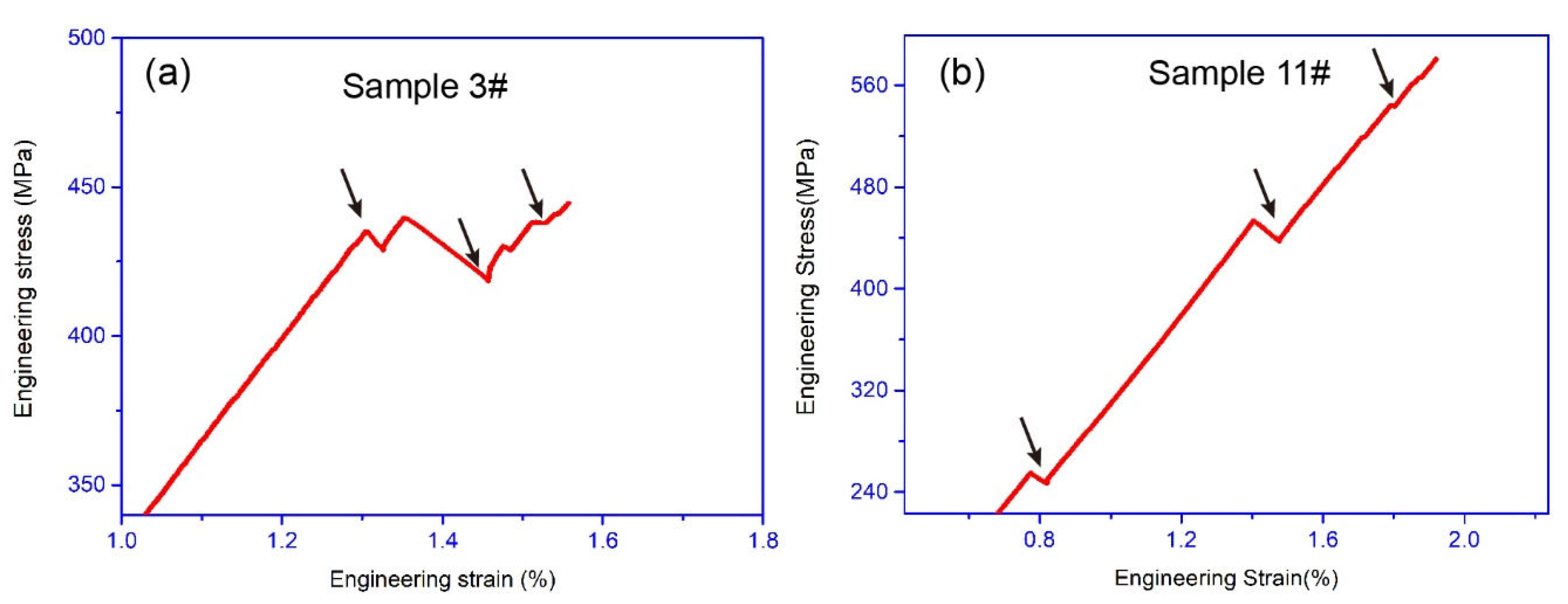
In the stress–strain curves, it can also be seen that the Mg-Cu-Ag-Gd BMG samples without Ni coating have no obvious yield phenomenon, which agrees with the reports [15,66,67,68,69], and their elastic deformation stages maintain a single linear shape, and all are typical brittle fractures (as shown in Figure 6a). The Mg-Cu-Ag-Gd BMG samples after nickel plating can exhibit yield characteristics, as shown in Figure 7a. By amplifying the stress–strain curve of the third Ni-plated sample, it can be found that the stress–strain curve has significant serrated ripples, which is a significant feature of ductile BMG alloys. This result indicates that nickel plating can improve the brittle deformation behavior of Mg-based BMG alloys to a certain extent. In addition, some nickel-plated BMG samples exhibit curve bending during the elastic deformation stage, as shown in Figure 7b. This is because brittle materials generally generate cracks due to local stress concentration during elastic loading. If the cracks propagate rapidly, it will lead to fracture, which is also the reason why some uncoated BGM samples fracture at about 300 MPa. However, under the geometric constraints of the Ni coating, even if cracks form under lower stress conditions, their propagation is effectively hindered by the coating, forming several serrated bends on the elastic section. This fully proves that the coating has an effective blocking effect on the propagation of cracks in Mg-based BMG alloys.
It is difficult to evaluate the mechanical properties of brittle materials due to their high dispersion of strength [70]. In order to solve this problem, as early as the late 1930s, Weibull introduced statistical methods into the processing of brittle material strength data based on the weakest link theory. The function of the Weibull distribution is:
P s = 1 P f = e V σ σ u σ 0 m
where Ps represents the probability of failure not occurring of the material under stress σ. V represents the volume of stress action. m represents the Weibull modulus, and the larger the value, the higher the safety factor. σu represents the stress threshold value, and the higher the value, the less dangerous it is. σ0 represents the scale parameter. Pf is the probability of failure of the material, which can be given by [71,72]:
P f = i + 0.5 n
Simplifying Equation (1) by taking two natural logarithms on both sides, the following equation can be obtained:
l n l n 1 1 P f = m · l n σ σ u + m · l n σ 0 + l n V
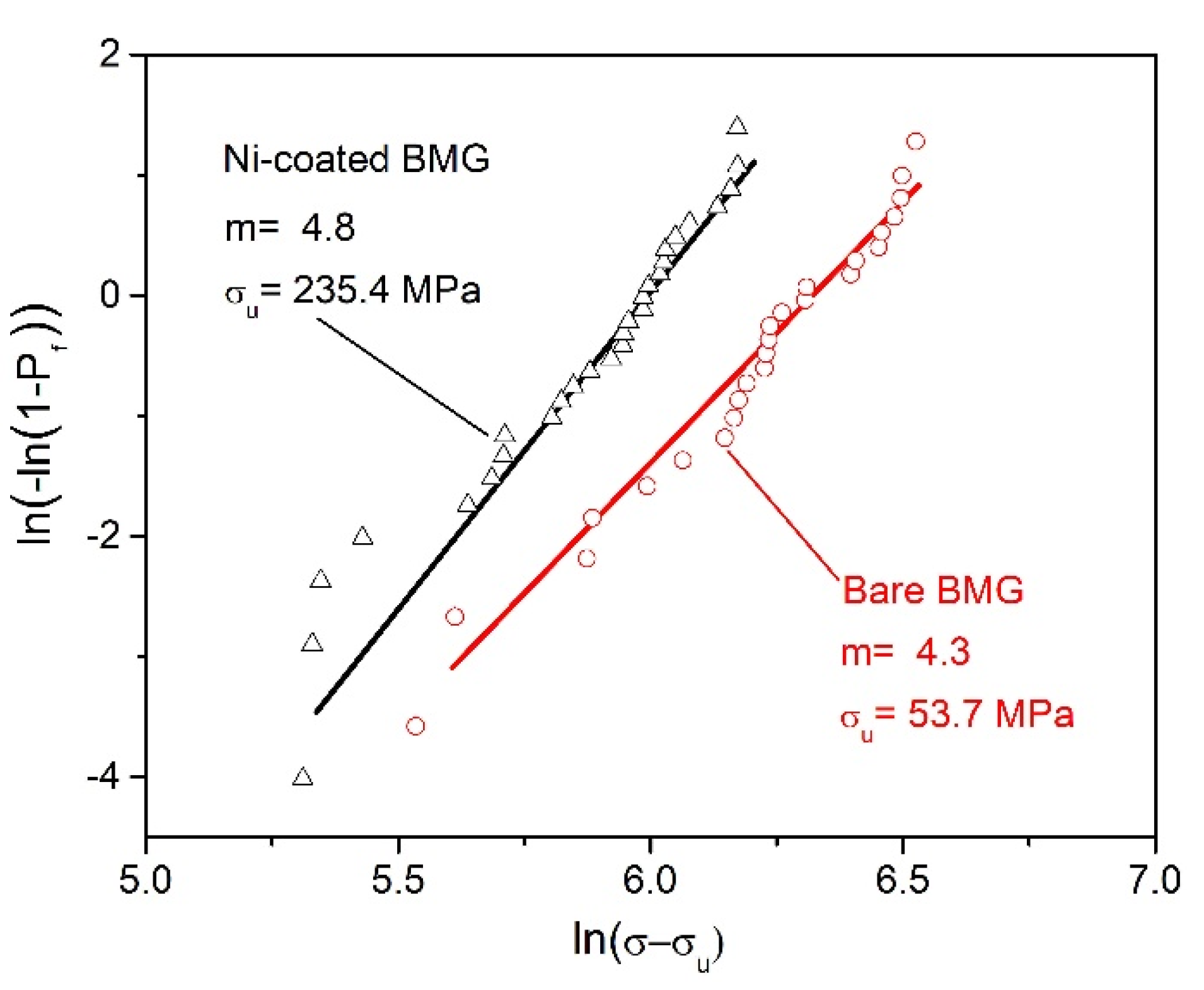
According to Equation (3), a Weibull curve can be drawn as shown in Figure 8. Using the linear regression calculation method to process the collected data points, the Weibull modulus m and the maximum safe stress value σu can be obtained. The m value of the nickel-plated BMG sample is 4.8, which is higher than the bare BMG sample (4.3), indicating that nickel plating treatment can improve the reliability of BMG strength. In addition, the σu value of the nickel-plated BMG sample is 235.4 MPa, which is more than four times the non-nickel-plated BMG sample, which also proves the significant role of nickel plating treatment in improving the safety of the Mg-based BMG. As is well-known, for brittle materials, the values of m and σu directly reflect their brittleness. Therefore, higher m and σu indicate that nickel plating treatment can effectively reduce the brittleness of Mg-Cu-Ag-Gd BMGs. This reduction in brittleness is related to the plastic toughness of the nickel plating layer itself. Even if the sample experiences brittle fracture, the Ni layer can absorb deformation energy through its own ductile fracture [73], thereby delaying the catastrophic fracture of the sample.

4. Discussion

For the strategy of using geometric confinement to increase the plasticity of BMGs, the greater the thickness of the geometric constraint layer, the greater its restrictive effect [40]. This work used a 50 μm coating to reduce the brittleness of the Mg-Cu-Ag-Gd BMG but did not achieve significant plasticity. The reasons can be attributed to the following two aspects: insufficient coating thickness and the interfacial bonding strength between the coating and the BMG substrate is not high (with defects and easy peeling). In addition, we found that although the Ni layer can withstand significant plastic deformation in layered composite materials, its plastic deformation is unstable [74]. Based on mechanical principles, the thickening of the Ni layer can improve its stability. Similarly, we believe that increasing the thickness of the coating also helps to improve the deformation stability of the Ni coating itself, which is beneficial for geometric constraint effects. In order to explore the thickness of the coating that can induce plastic deformation, we used finite element simulation to analyze the geometric limiting effect of the coating. Figure 9 shows the stress distribution on the sample observed from different perspectives when a stress of 1000 MPa is applied. In Figure 9a, it can be seen that the maximum stress at the defect occurs on the left side of the defect, which agrees with the report [47], indicating that shear bands or cracks will initiate from the defect.
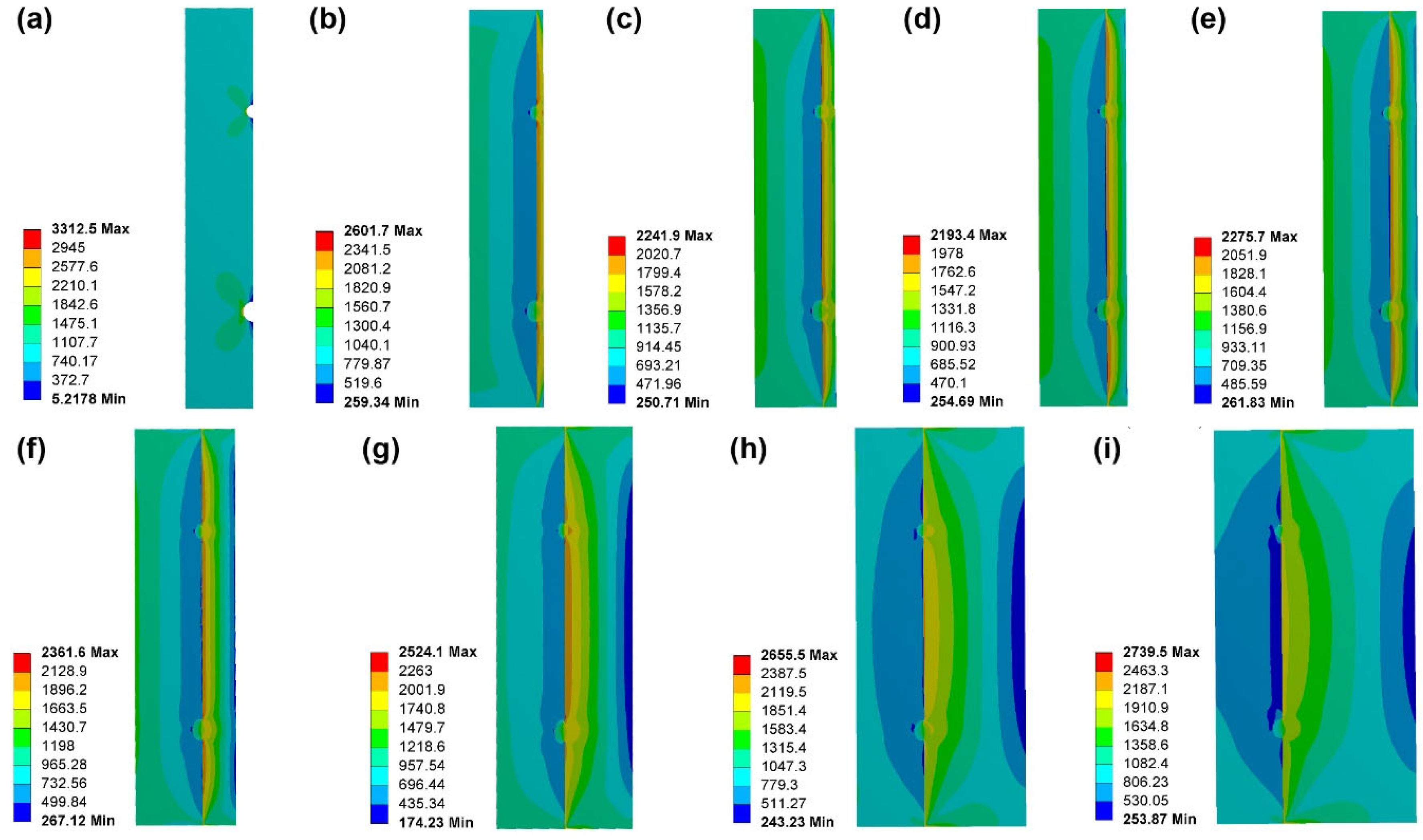
Figure 10 shows the effect of Ni coatings with different thicknesses on the stress distribution of BMG-compressed samples. Compared with the coated sample (Figure 10b–i) and the uncoated sample (Figure 10a), the presence of the Ni coating transferred the maximum stress in the compressed sample from the left end of the defect into the coating, alleviating the risk of failure caused by high stress levels. This can be attributed to the high work hardening index of Ni metal [75], which leads to a significant increase in stress borne by the Ni layer compared to the BMG matrix as the strain increases. At the same time, the existence of the Ni coating significantly improves the stress distribution state, with the large stress part uniformly distributed on the surface of the coating, and the stress concentration at the two defects is also dispersed on the interface between the coating and the substrate, increasing the stress area by transferring the local stress inside the defects to a larger area of the Ni coating. In addition, as the coating thickens, the stress on the BMG substrate gradually decreases, reducing the tendency for surface defects to induce cracking. We know that in layered composite materials, Ni layers often fail in the form of interlayer delamination [76], and reducing interlayer stress is beneficial for reducing delamination tendency. Therefore, the phenomenon of reducing the stress between the Ni layer and the substrate in Figure 9 is beneficial for reducing the trend of interlayer delamination and exerting the geometric constraint effect of the coating.
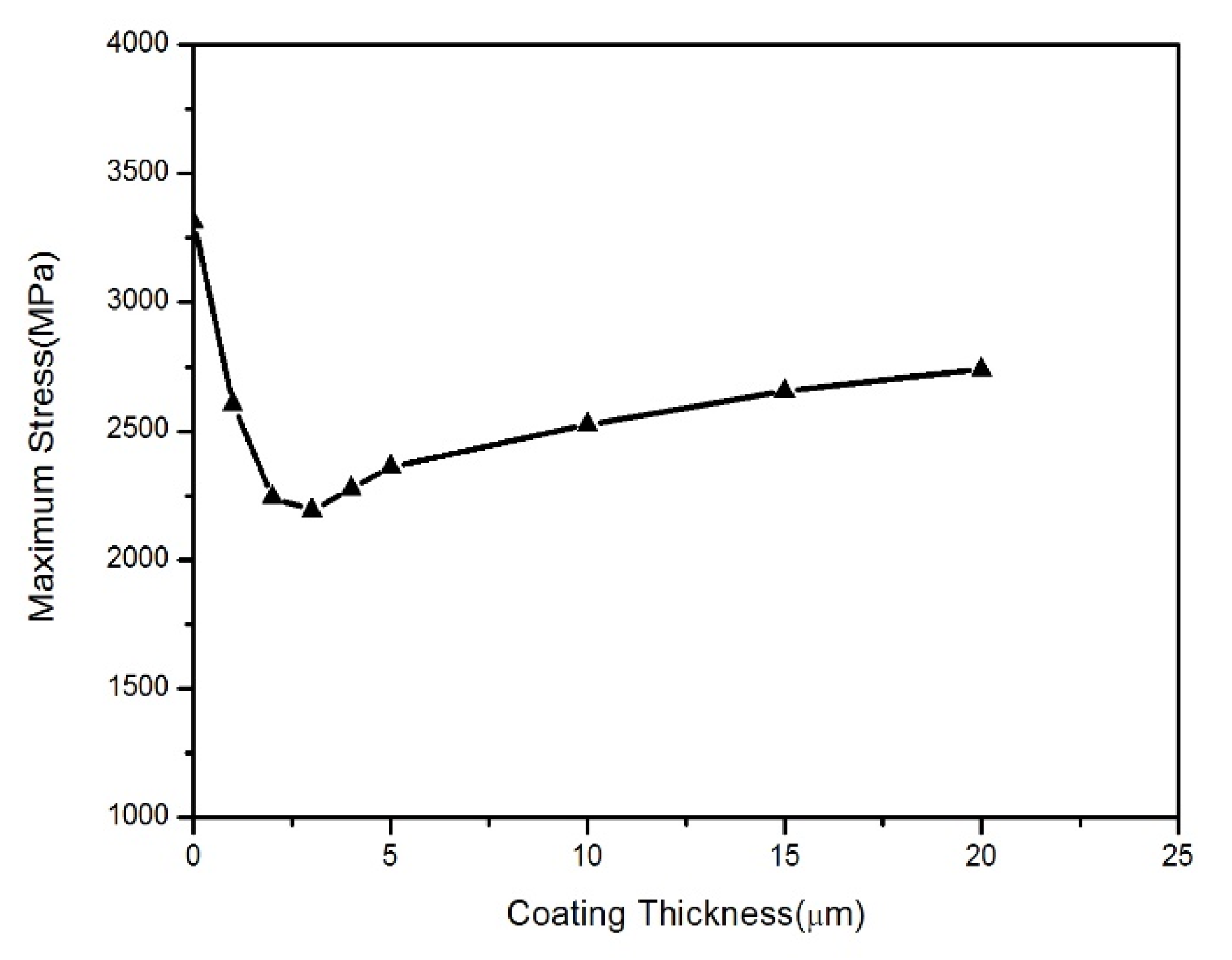
Based on the plating thickness and maximum stress data obtained in Figure 10, we plotted the plating thickness vs. maximum stress curve, as shown in Figure 11. In Figure 11, it can be seen clearly that as the coating thickens, the maximum stress shows a trend of first decreasing and then increasing. Moreover, there is an optimal coating thickness (3 μm, about 30% of the sample width of 10 μm) for the sample, and coatings below this thickness value often need to withstand greater stress at the interface between the coating and the substrate due to the very thin coating, resulting in the poor cracking resistance or geometric confinement effect of the coating. However, the Ni coatings with a thickness higher than this value tend to peel off from the BMG substrate due to excessive internal stress, which is detrimental to limiting crack initiation. Therefore, when formulating BMG nickel plating process parameters, it is necessary to consider the impact of the critical thickness of the coating.
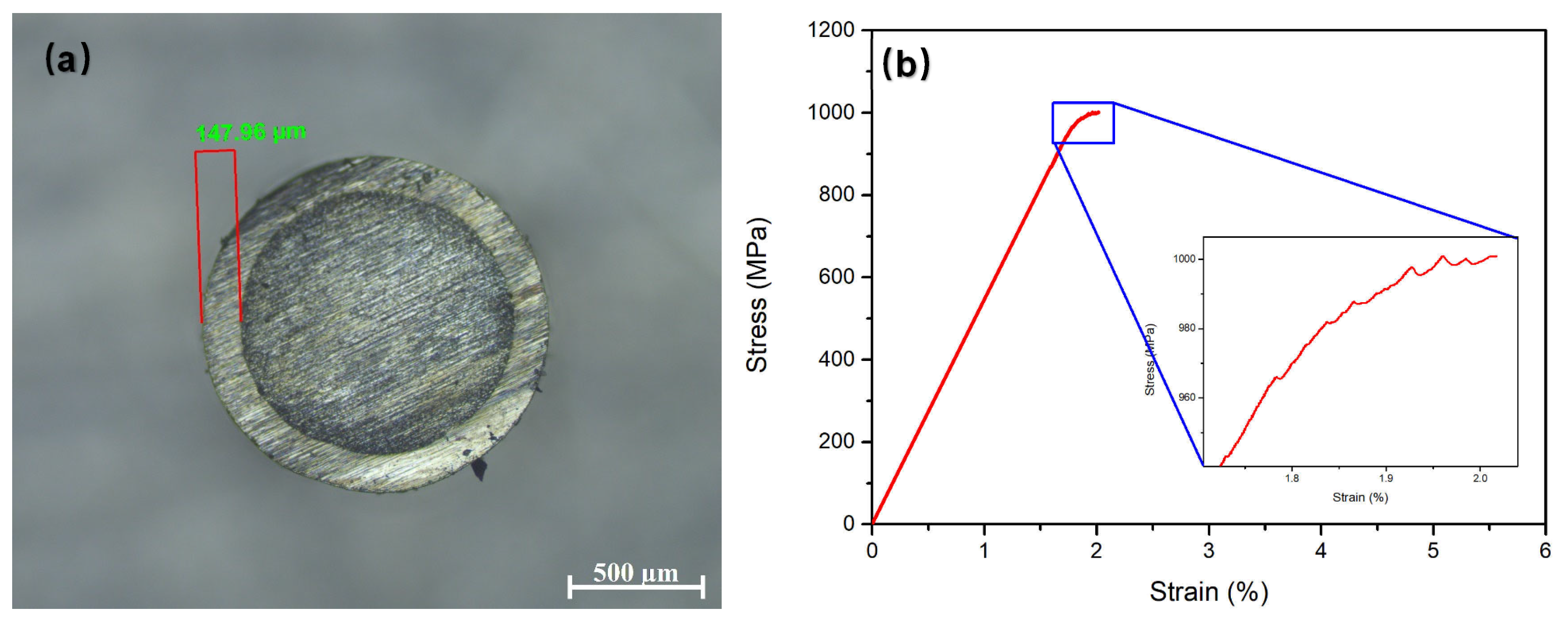
In the above finite element simulation results, it can be concluded that when the coating thickness is about 30% of the thickness of the BMG matrix (i.e., its radius for bars), the coating can achieve the best effect of reducing stress concentration in the samples. To verify this, we extended the electroplating time to 3 h without changing other process parameters and conducted nickel plating on a BMG rod with a diameter of 1 mm. The OM photos of the cross-section of the coating obtained are shown in Figure 12a. The thickness of the nickel plating layer is about 148 μm, approximately 30% of the radius. We conducted uniaxial compression experiments on this sample, and the stress–strain curve obtained is shown in Figure 12b. It can be seen that the plastic strain is about 0.3% and there is an obvious plastic deformation feature (curving for yielding) at the end of the stress–strain curve, and the enlarged image (Figure 12b inset) also shows serrated features, indicating that the ~150 μm coating has a significant geometric confinement effect on improving the plasticity of the Mg-Cu-Ag-Gd BMG sample with a diameter of 1 mm. In addition, the strength of the BMG sample has also increased to around 1000 MPa, indicating a significant improvement in the room temperature mechanical properties of the BMG matrix, which verifies the results of finite element simulation.
Although thickness optimization can achieve limited improvement in the plasticity of the Mg-Cu-Ag-Gd BMG, the actual effect of this geometric constraint on Mg-based BMGs is weaker compared to the Zr-based, Ti-based, and Fe-based BMGs. This may be related to the following two aspects: firstly, the hardness of the nickel plating layer is relatively high and is difficult to deform, making it unable to effectively absorb deformation energy. This means that some softer coatings, such as copper plating, may be more effective for those particularly brittle Mg-based BMGs; secondly, the damage control of the Mg-based BMG surface during the electroplating process is not good enough, resulting in the easy peeling of the Ni coating. Therefore, improving chemical zinc deposition prior to the nickel plating process, or developing other new pre-plating intermediate layer technologies, is of great significance for the electroplating or chemical plating treatment of Mg-based BMG alloys.

5. Conclusions

In the present work, we have prepared an electroplating Ni coating on the surface of a classic Mg59.5Cu22.9Ag11Gd6.6 bulk metallic glass (BMG). The geometric confinement effect of the plated Ni coating was evaluated using quasi-static compressive mechanical performance testing and finite element analysis (FEA) methods. The main conclusions obtained are as follows:
(1)
The surface smoothness of the electroplated Ni coating was improved by adding the brightener nano alumina to enhance the adhesion between the coating and the Mg59.5Cu22.9Ag11Gd6.6 BMG. The main electroplating process parameters are nano Al2O3 1 g/L, an electroplating temperature of 50 °C, and an electroplating time of 3 h;
(2)
The mechanical properties of the Ni-plated BMG were tested using the uniaxial compression method, and it was found that the coating thickness significantly affects the geometric constraint effect. The 50 μm Ni coating did not significantly improve the plasticity of the BMG, but it reduced the fluctuation value of fracture strength from 429 MPa to 276 MPa, with a reduction of up to 36%. The ~148 μm Ni coating can improve the plasticity of BMG up to 0.3%. This indicates that electroplating Ni can improve the strength stability and plastic deformation ability of brittle Mg-based BMGs;
(3)
The Weibull statistical analysis results showed that compared with the BMG sample without Ni plating, the safe stress value and Weibull modulus of the BMG sample after Ni plating increased from 54.7 MPa and 4.3 to 235.4 MPa and 4.8, respectively, indicating that the Ni plating treatment can significantly reduce the brittleness of Mg-based BMGs and improve their reliability;
(4)
The FEA results showed that as the thickness of the coating increases, the maximum stress concentration level first decreases rapidly and then slowly increases. When the coating thickness is about 30% of the thickness of BMG substrates, the maximum stress level is the lowest. This indicates that the coating thickness does not necessarily need to be particularly large for achieving an ideal geometric constraint, but rather an optimal value is required, i.e., 30% of the substrate thickness. This result provides a new understanding and perspective for the development of geometric constraint principles and technologies in BMGs.

Author Contributions

Investigation and writing—original draft preparation, J.Z.; investigation and writing—original draft preparation, J.L.; data curation and formal analysis, M.J.; writing—review and editing, L.Z.; methodology and visualization, W.Y.; conceptualization and supervision, Y.Q.; supervision, writing—review and editing, project administration, and funding acquisition, X.W. All authors have read and agreed to the published version of the manuscript.

Funding

This research was funded by the “Natural Science Foundation of Hebei Province, China, grant number E2016202332, E2021202140, and E2022202055”, the “Science Research Project of Hebei Education Department, grant number ZD2022099” and the “Hebei Province funding project for introducing overseas persons, grant number C20220314”.

Institutional Review Board Statement

Not applicable.

Informed Consent Statement

Not applicable.

Data Availability Statement

Any further detailed data may be obtained from the authors upon reasonable request.

Conflicts of Interest

The authors declare no conflict of interest.

References

  1. Johnson, W.L. Bulk Glass-Forming Metallic Alloys: Science and Technology 1998 MRS Medal Award Lecture, Presented at Symposium MM. In Proceedings of the Symposium MM on Bulk Metallic Glasses at the 1998 MRS Fall Meeting, Boston, MA, USA, 1–3 December 1999; pp. 311–339. [Google Scholar] [CrossRef]
  2. Xu, J.; Ramamurty, U.; Ma, E. The fracture toughness of bulk metallic glasses. JOM 2010, 62, 10–18. [Google Scholar] [CrossRef]
  3. Savaedi, Z.; Motallebi, R.; Mirzadeh, H.; Malekan, M. Superplasticity of bulk metallic glasses (BMGs): A review. J. Non-Crystal. Solids 2022, 583, 121503. [Google Scholar] [CrossRef]
  4. Ritchie, R.O. Toughening materials: Enhancing resistance to fracture. Philos. Trans. R. Soc. A 2021, 379, 20200437. [Google Scholar] [CrossRef]
  5. El Hafi, T.; Bajjou, O.; Jabraoui, H.; Louafi, J.; Mazroui, M.; Lachtioui, Y. Effects of cooling rate on the glass formation process and the microstructural evolution of Silver mono-component metallic glass. Chem. Phys. 2023, 569, 111873. [Google Scholar] [CrossRef]
  6. Lian, J.; Song, R.; Chen, Y.; Dai, L. Vortex Evolution Behavior in Self-Assembly of Flow Units in Metallic Glasses. Acta Mech. Solida Sin. 2023. [Google Scholar] [CrossRef]
  7. Zhao, Z.; Li, C.; Liu, Y.; Li, C.; Kou, S. Rejuvenation and Malleability Enhancement of Zr-Based Metallic Glass by Sub-Tg Annealing and Cryogenic Thermal Cycle Treatment. J. Mater. Eng. Perform. 2023, 32, 8430–8440. [Google Scholar] [CrossRef]
  8. Zhou, X.; Chen, C. Atomistic investigation of the intrinsic toughening mechanism in metallic glass. Comp. Mater. Sci. 2016, 117, 188–194. [Google Scholar] [CrossRef]
  9. Dong, Z.; Wang, D.; Wu, Y.; Geng, Y.; Chen, F.; Guo, P.; Qiao, Y.; Li, X.; Wang, Y. Nano-voids formation at the interaction sites of shear bands in a Zr-based metallic glass. Eur. Phys. J. Appl. Phys. 2022, 97, 91. [Google Scholar] [CrossRef]
  10. Gurbuz, E.; Sanyal, B. Tuning of lattice thermal conductivity of amorphous Fe0.85Zr0.15 by nanostructured voids, pressure and temperature. J. Non-Cryst. Solids 2023, 616, 122430. [Google Scholar] [CrossRef]
  11. Noell, P.J.; Sills, R.B.; Benzerga, A.A.; Boyce, B.L. Void nucleation during ductile rupture of metals: A review. Prog. Mater. Sci. 2023, 135, 101085. [Google Scholar] [CrossRef]
  12. Hong, Y.; Wang, H.; Li, X.; Zhong, L.; Chen, H.; Zhang, Z.; Cao, P.; Ritchie, R.O.; Wang, J. Structural heterogeneity governing deformability of metallic glass. Matter 2023, 6, 1160–1172. [Google Scholar] [CrossRef]
  13. Wang, T.; Zhou, Y.; Zhang, L. Chemical and structural heterogeneity improve the plasticity of a Zr-based bulk metallic glass at low-temperature annealing. J. Non-Cryst. Solids 2023, 603, 122115. [Google Scholar] [CrossRef]
  14. Wu, G.; Liu, S.; Wang, Q.; Rao, J.; Xia, W.; Yan, Y.-Q.; Eckert, J.; Liu, C.; Ma, E.; Shan, Z.-W. Substantially enhanced homogeneous plastic flow in hierarchically nanodomained amorphous alloys. Nat. Commun. 2023, 14, 3670. [Google Scholar] [CrossRef]
  15. Wang, S.-G.; Shi, L.-L.; Xu, J. Mg-based bulk metallic glasses: Elastic properties and their correlations with toughness and glass transition temperature. J. Mater. Res. 2011, 26, 923–933. [Google Scholar] [CrossRef]
  16. Liu, H.; Li, J.; Zhang, J.; Gong, P.; Yang, W.; Zhao, L.; Wang, X. Design Optimization and Mechanical Properties of SiC Particle Reinforced Ti-Based Metallic Glass Matrix Composite. Materials 2023, 16, 5323. [Google Scholar] [CrossRef] [PubMed]
  17. Yin, H.L.; Liu, S.Q.; Zhao, L.C.; Cui, C.X.; Wang, X. Vacuum infiltration molding and mechanical property of short carbon fiber reinforced Ti-based metallic glass matrix composite. J. Mater. Proc. Technol. 2021, 295, 117151. [Google Scholar] [CrossRef]
  18. Yin, H.L.; Yang, W.; Zhao, L.C.; Hu, X.M.; Liu, S.Q.; Cui, C.X.; Wang, X. Fabrication and mechanical property of three-dimensional carbon fiber reinforced Mg-based bulk metallic glass matrix composite. Mater. Sci. Eng. A 2022, 839, 142853. [Google Scholar] [CrossRef]
  19. Hofmann, D.C.; Suh, J.-Y.; Wiest, A.; Duan, G.; Lind, M.-L.; Demetriou, M.D.; Johnson, W.L. Designing metallic glass matrix composites with high toughness and tensile ductility. Nature 2008, 451, 1085–1089. [Google Scholar] [CrossRef]
  20. Qiao, J.; Jia, H.; Liaw, P.K. Metallic glass matrix composites. Mater. Sci. Eng. R 2016, 100, 1–69. [Google Scholar] [CrossRef]
  21. Zhang, C.; Zhang, H.; Sun, Q.; Liu, K. Mechanical properties of Zr41.2Ti13.8Ni10Cu12.5Be22.5 bulk metallic glass with different geometric confinements. Results Phys. 2018, 8, 1–6. [Google Scholar] [CrossRef]
  22. Yu, P.; Liu, Y.H.; Wang, G.; Bai, H.Y.; Wang, W.H. Enhance plasticity of bulk metallic glasses by geometric confinement. J. Mater. Res. 2007, 22, 2384–2388. [Google Scholar] [CrossRef]
  23. Li, J.; Cao, Q.; Zhou, Y. Microstructure of Cu60Zr20Ti20 bulk metallic glass rolled at different strain rates. Sci. China Ser. G 2008, 51, 394–399. [Google Scholar] [CrossRef]
  24. Nieh, T.G.; Schuh, C.; Wadsworth, J.; Li, Y. Strain rate-dependent deformation in bulk metallic glasses. Intermetallics 2002, 10, 1177–1182. [Google Scholar] [CrossRef]
  25. Sergueeva, A.V.; Mara, N.A.; Branagan, D.J.; Mukherjee, A.K. Strain rate effect on metallic glass ductility. Scr. Mater. 2004, 50, 1303–1307. [Google Scholar] [CrossRef]
  26. Nieh, T.G.; Yang, Y.; Lu, J.; Liu, C.T. Effect of surface modifications on shear banding and plasticity in metallic glasses: An overview. Prog. Nat. Sci. Mater. Int. 2012, 22, 355–363. [Google Scholar] [CrossRef]
  27. Zhang, Y.; Wang, W.H.; Greer, A.L. Making metallic glasses plastic by control of residual stress. Nat. Mater. 2006, 5, 857–860. [Google Scholar] [CrossRef] [PubMed]
  28. Chen, L.Y.; Ge, Q.; Qu, S.; Jiang, J.Z. Stress-induced softening and hardening in a bulk metallic glass. Scr. Mater. 2008, 59, 1210–1213. [Google Scholar] [CrossRef]
  29. Wang, L.; Bei, H.; Gao, Y.F.; Lu, Z.P.; Nieh, T.G. Effect of residual stresses on the hardness of bulk metallic glasses. Acta Mater. 2011, 59, 2858–2864. [Google Scholar] [CrossRef]
  30. Mear, F.O.; Vaughan, G.; Yavari, A.R.; Greer, A.L. Residual-stress distribution in shot-peened metallic-glass plate. Philos. Mag. Lett. 2008, 88, 757–766. [Google Scholar] [CrossRef]
  31. Mear, F.O.; Doisneau, B.; Yavari, A.R.; Greer, A.L. Structural effects of shot-peening in bulk metallic glasses. J. Alloys Compd. 2009, 483, 256–259. [Google Scholar] [CrossRef]
  32. Fan, J.T.; Chen, A.Y.; Fu, M.W.; Lu, J. A novel structural gradient metallic glass composite with enhanced mechanical properties. Scr. Mater. 2009, 61, 608–611. [Google Scholar] [CrossRef]
  33. Wang, Q.; Yang, Y.; Jiang, H.; Liu, C.T.; Ruan, H.H.; Lu, J. Superior Tensile Ductility in Bulk Metallic Glass with Gradient Amorphous Structure. Sci. Rep. 2014, 4, 4757. [Google Scholar] [CrossRef] [PubMed]
  34. Fan, J.; Chen, A.; Wang, J.; Shen, J.; Lu, J. Improved plasticity and fracture toughness in metallic glasses via surface crystallization. Intermetallics 2011, 19, 1420–1427. [Google Scholar] [CrossRef]
  35. Chen, B.; Li, Y.; Yi, M.; Li, R.; Pang, S.; Wang, H.; Zhang, T. Optimization of mechanical properties of bulk metallic glasses by residual stress adjustment using laser surface melting. Scr. Mater. 2012, 66, 1057–1060. [Google Scholar] [CrossRef]
  36. Wu, G.; Li, R.; Liu, Z.; Chen, B.; Li, Y.; Cai, Y.; Zhang, T. Induced multiple heterogeneities and related plastic improvement by laser surface treatment in CuZr-based bulk metallic glass. Intermetallics 2012, 24, 50–55. [Google Scholar] [CrossRef]
  37. Raghavan, R.; Ayer, R.; Jin, H.W.; Marzinsky, C.N.; Ramamurty, U. Effect of shot peening on the fatigue life of a Zr-based bulk metallic glass. Scr. Mater. 2008, 59, 167–170. [Google Scholar] [CrossRef]
  38. Li, H.; Li, L.; Fan, C.; Choo, H.; Liaw, P.K. Nanocrystalline coating enhanced ductility in a Zr-based bulk metallic glass. J. Mater. Res. 2007, 22, 508–513. [Google Scholar] [CrossRef]
  39. Ren, L.W.; Wang, Z.; Meng, M.M.; Tian, H.; Yang, H.J.; Qiao, J.W. Plasticity enhancement in bulk metallic glasses by electroless plating with Ni-P amorphous films. J. Non-Cryst. Solids 2015, 430, 115–119. [Google Scholar] [CrossRef]
  40. Qiu, S.-B.; Yao, K.-F. Novel application of the electrodeposition on bulk metallic glasses. Appl. Surf. Sci. 2008, 255, 3454–3458. [Google Scholar] [CrossRef]
  41. Choi, Y.C.; Hong, S.I. Effect of crystallization and surface treatment on deformation and fracture of Zr-Ti-Cu-Ni-Be bulk metallic glass. Int. J. Mod. Phys. B 2009, 23, 1270–1275. [Google Scholar] [CrossRef]
  42. Choi, Y.C.; Hong, S.I. Enhancement of plasticity in Zr-base bulk metallic glass by soft metal plating. Scr. Mater. 2009, 61, 481–484. [Google Scholar] [CrossRef]
  43. Chen, W.; Chan, K.C.; Chen, S.H.; Guo, S.F.; Li, W.H.; Wang, G. Plasticity enhancement of a Zr-based bulk metallic glass by an electroplated Cu/Ni bilayered coating. Mater. Sci. Eng. A 2012, 552, 199–203. [Google Scholar] [CrossRef]
  44. Ren, L.W.; Yang, F.Q.; Jiao, Z.M.; Yang, H.J.; Wang, Z.H.; Qiao, J.W. Plasticity enhancement in Ni-P amorphous alloy/Ni/Zr-based metallic glass composites with a sandwich structure. Mater. Sci. Eng. A 2015, 643, 175–182. [Google Scholar] [CrossRef]
  45. Ren, L.W.; Meng, M.M.; Wang, Z.; Yang, F.Q.; Yang, H.J.; Zhang, T.; Qiao, J.W. Enhancement of plasticity in Zr-based bulk metallic glasses electroplated with copper coatings. Intermetallics 2015, 57, 121–126. [Google Scholar] [CrossRef]
  46. Chen, W.; Chan, K.C.; Guo, S.F.; Yu, P. Plasticity improvement of an Fe-based bulk metallic glass by geometric confinement. Mater. Lett. 2011, 65, 1172–1175. [Google Scholar] [CrossRef]
  47. Li, J.-F.; Wang, X.; Yang, G.-N.; Chen, N.; Liu, X.; Yao, K.-F. Enhanced plasticity of a Fe-based bulk amorphous alloy by thin Ni coating. Mater. Sci. Eng. A 2015, 645, 318–322. [Google Scholar] [CrossRef]
  48. Wang, X.; Hu, X.; Zhao, L.; Jiang, D.; Chen, P.; Wang, P.; Zhang, Z.; Liu, S.; Cui, C. Improved Plasticity of Ti-Based Bulk Metallic Glass at Room Temperature by Electroless Thin Nickel Coating. Metals 2017, 7, 562. [Google Scholar] [CrossRef]
  49. Cao, J.W.; Han, J.G.; Guo, Z.H.; Zhao, W.B.; Guo, Y.Q.; Xia, Z.H.; Qiao, J.W. Plasticity enhancement of high-entropy bulk metallic glasses by electroless plating with Ni-P amorphous films. Mater. Sci. Eng. A 2016, 673, 141–147. [Google Scholar] [CrossRef]
  50. Song, Y.W.; Shan, D.Y.; Han, E.H. High corrosion resistance of electroless composite plating coatings on AZ91D magnesium alloys. Electrochim. Acta 2008, 53, 2135–2143. [Google Scholar] [CrossRef]
  51. Zheng, Q.; Xu, J.; Ma, E. High glass-forming ability correlated with fragility of Mg-Cu(Ag)-Gd alloys. J. Appl. Phys. 2007, 102, 113519. [Google Scholar] [CrossRef]
  52. Wang, S.-G.; Sun, M.-Y.; Song, Z.-Q.; Xu, J. Cast defects induced sample-size dependency on compressive strength and fracture toughness of Mg-Cu-Ag-Gd bulk metallic glass. Intermetallics 2012, 29, 123–132. [Google Scholar] [CrossRef]
  53. Wang, X. Surface Crystallization in Mg-Based Bulk Metallic Glass during Copper Mold Casting. Adv. Mater. Sci. Eng. 2014, 2014, 798479. [Google Scholar] [CrossRef]
  54. Louzguine-Luzgin, D.V.; Hitosugi, T.; Chen, N.; Ketov, S.V.; Shluger, A.; Zadorozhnyy, V.Y.; Caron, A.; Gonzales, S.; Qin, C.L.; Inoue, A. Investigation of transparent magnetic material formed by selective oxidation of a metallic glass. Thin Solid Film. 2013, 531, 471–475. [Google Scholar] [CrossRef]
  55. Yamada, R.; Nomura, N.; Saida, J.; Kawasaki, A. Selective oxidation/crystallization and their patterning on metallic glass by laser irradiation. J. Alloys Compd. 2017, 727, 549–554. [Google Scholar] [CrossRef]
  56. Wang, X.; Shao, Y.; Yao, K.-F. Chemical composition dependence of atomic oxygen erosion resistance in Cu-rich bulk metallic glasses. Chin. Sci. Bull. 2012, 57, 4801–4804. [Google Scholar] [CrossRef]
  57. Lim, J.H.; Park, E.C.; Joo, J.; Jung, S.-B. Effect of Additives on Microstructure and Mechanical Properties of Nickel Plate/Mask Fabricated by Electroforming Process. J. Electrochem. Soc. 2009, 156, D108–D112. [Google Scholar] [CrossRef]
  58. Mohanty, U.S.; Tripathy, B.C.; Singh, P.; Keshavarz, A.; Iglauer, S. Roles of organic and inorganic additives on the surface quality, morphology, and polarization behavior during nickel electrodeposition from various baths: A review. J. Appl. Electrochem. 2019, 49, 847–870. [Google Scholar] [CrossRef]
  59. Rajabalizadeh, Z.; Seifzadeh, D. Application of electroless Ni-P coating on magnesium alloy via CrO3/HF free titanate pretreatment. Appl. Surf. Sci. 2017, 422, 696–709. [Google Scholar] [CrossRef]
  60. Hu, R.; Su, Y.; Liu, Y.; Liu, H.; Chen, Y.; Cao, C.; Ni, H. Deposition Process and Properties of Electroless Ni-P-Al2O3 Composite Coatings on Magnesium Alloy. Nano Res. Lett. 2018, 13, 198. [Google Scholar] [CrossRef]
  61. Heakal, F.E.-T.; Maanoum, M.A. Role of Some Plating Parameters in the Properties of Ni-P/Al2O3 Nanocomposite Coatings on Mg alloy. Int. J. Electrochem. Sci. 2016, 11, 7198–7215. [Google Scholar] [CrossRef]
  62. Chen, J.; Yu, G.; Hu, B.; Liu, Z.; Ye, L.; Wang, Z. A zinc transition layer in electroless nickel plating. Surf. Coat. Tech. 2006, 201, 686–690. [Google Scholar] [CrossRef]
  63. Zheng, Q.; Cheng, S.; Strader, J.H.; Ma, E.; Xu, J. Critical size and strength of the best bulk metallic glass former in the Mg–Cu–Gd ternary system. Scr. Mater. 2007, 56, 161–164. [Google Scholar] [CrossRef]
  64. Wang, X.; Zhao, L.; Hu, X.; Cheng, Y.; Liu, S.; Chen, P.; Cui, C. Fabrication and Mechanical Behavior of Ex Situ Mg-Based Bulk Metallic Glass Matrix Composite Reinforced with Electroless Cu-Coated SiC Particles. Materials 2017, 10, 1371. [Google Scholar] [CrossRef] [PubMed]
  65. Wu, W.F.; Li, Y.; Schuh, C.A. Strength, plasticity and brittleness of bulk metallic glasses under compression: Statistical and geometric effects. Philos. Mag. 2008, 88, 71–89. [Google Scholar] [CrossRef]
  66. Wang, J.-f.; Wu, X.; Pan, F.-s.; Tang, A.-t.; Ding, P.-d.; Liu, R.-p. Microstructure and mechanical properties of Mg-Cu-Y-Zn bulk metallic glass matrix composites prepared in low vacuum. Trans. Nonferr. Metal Soc. 2008, 18, S278–S282. [Google Scholar] [CrossRef]
  67. Yin, J.; Yuan, G.; Chen, L.; Zhou, Q. Effects of sample sizes on compressive mechanical behaviors of Mg-based bulk metallic glasses. Chin. J. Nonferrous Met. 2011, 21, 588–596. [Google Scholar]
  68. Park, E.S.; Kim, D.H. Formation of Mg-Cu-Ni-Ag-Zn-Y-Gd bulk glassy alloy by casting into cone-shaped copper mold in air atmosphere. J. Mater. Res. 2005, 20, 1465–1469. [Google Scholar] [CrossRef]
  69. Park, E.S.; Chang, H.J.; Kim, D.H. Mg-rich Mg-Ni-Gd ternary bulk metallic glasses with high compressive specific strength and ductility. J. Mater. Res. 2007, 22, 334–338. [Google Scholar] [CrossRef]
  70. Han, Z.; Tang, L.C.; Xu, J.; Li, Y. A three-parameter Weibull statistical analysis of the strength variation of bulk metallic glasses. Scr. Mater. 2009, 61, 923–926. [Google Scholar] [CrossRef]
  71. Ma, Y.; Tang, X.; Wang, X.; Zhang, M.; Hu, H.; Gong, P.; Wang, X. Preparation and mechanical properties of tungsten-particle-reinforced Zr-based bulk-metallic-glass composites. Mater. Sci. Eng. A 2021, 815, 141312. [Google Scholar] [CrossRef]
  72. Gong, P.; Wang, X.; Yao, K. Effects of alloying elements on crystallization kinetics of Ti-Zr-Be bulk metallic glass. J. Mater. Sci. 2016, 51, 5321–5329. [Google Scholar] [CrossRef]
  73. Liu, S.; Tayyebi, M.; Assari, A.H.; Polkowska, A.; Lech, S.; Polkowski, W. Microstructure, Texture and Tensile Properties of Nickel/Titanium Laminated Composites Produced by Cross Accumulative Roll Bonding Process. Met. Mater. Int. 2023. [Google Scholar] [CrossRef]
  74. Ye, Q.; Li, X.; Tayyebi, M.; Assari, A.H.; Polkowska, A.; Lech, S.; Polkowski, W.; Tayebi, M. Effect of heat treatment parameters on microstructure evolution, tensile strength, wear resistance, and fracture behavior of Ni–Ti multilayered composites produced by cross-accumulative roll bonding. Archiv. Civ. Mech. Eng. 2022, 23, 27. [Google Scholar] [CrossRef]
  75. Huang, J.; Tayyebi, M.; Assari, A.H. Effect of SiC particle size and severe deformation on mechanical properties and thermal conductivity of Cu/Al/Ni/SiC composite fabricated by ARB process. J. Manuf. Process. 2021, 68, 57–68. [Google Scholar] [CrossRef]
  76. Luo, J.; Yarigarravesh, M.; Assari, A.H.; Amin, N.H.; Tayyebi, M.; Paidar, M. Investigating the solid-state diffusion at the interface of Ni/Ti laminated composite. J. Manuf. Process. 2022, 75, 670–681. [Google Scholar] [CrossRef]
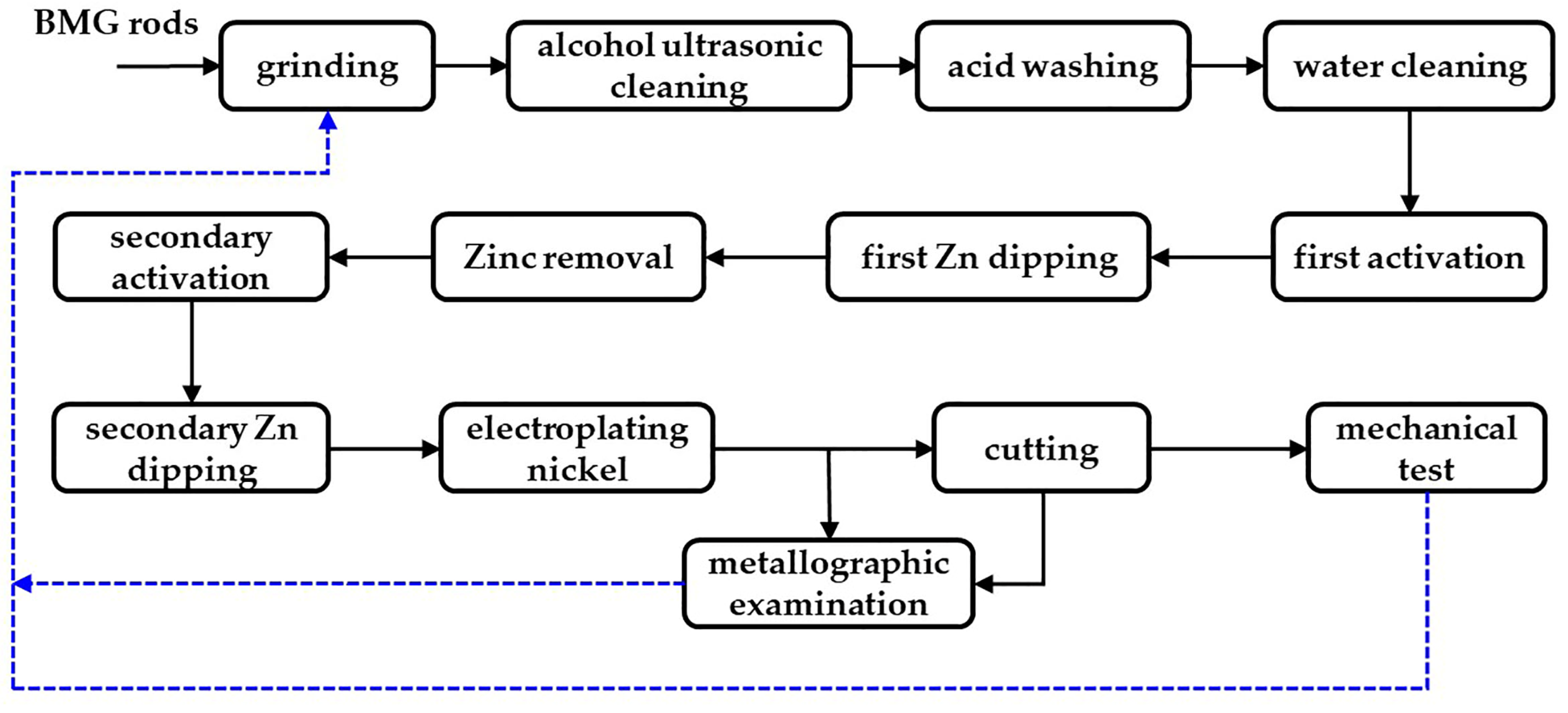
Figure 1. The electroplating process flowchart of the Mg59.5Cu22.9A11Gd6.6 BMG samples.
Coatings 13 01598 g001
Figure 2. Finite element model of the uncoated BMG samples.
Coatings 13 01598 g002
Figure 3. XRD patterns of the Ni-electroplated surface on the Mg-Cu-Ag-Gd BMG together with the cross-section of the bare BMG sample.
Coatings 13 01598 g003
Figure 4. Optical micrographs of the BMG samples after acid pickling and electroplating treatment. (a) Acid-washed surface; (b) cross-section of the sample after acid washing treatment; (c) electroplated Ni-treated surface; (d) cross-section of the sample after electroplating Ni treatment.
Coatings 13 01598 g004
Figure 5. SEM images of the surface of different electroplating Ni coating: (a) with nano Al2O3 and (b) without nano Al2O3; the inset is a low magnification image; (c) SEM image of the cross-section of the Ni coating with nano Al2O3; (d) EDS line scan analysis performed on the white line in (c).
Coatings 13 01598 g005
Figure 6. Compression engineering stress–strain curves of (a) the bare Mg-Cu-Ag-Gd BMG samples and (b) the Ni-coated BMG samples.
Coatings 13 01598 g006
Figure 7. The locally amplified stress–strain curves of the special nickel-plated BMG samples with serrated features of (a) Sample 3 and (b) Sample 11.
Coatings 13 01598 g007
Figure 8. Weibull analysis of the nickel-plated and non-nickel-plated BMG samples.
Coatings 13 01598 g008
Figure 9. Compressive stress distribution of the uncoated BMG sample with defects using different perspectives of (a) 3D and (b) 2D.
Coatings 13 01598 g009
Figure 10. Contour maps of the equivalent stress of the BMG samples with different thicknesses of Ni coatings: (a) uncoated BMG samples; (b) 1 μm coating; (c) 2 μm coating; (d) 3 μm coating; (e) 4 μm coating; (f) 5 μm coating; (g) 10 μm coating; (h) 15 μm coating; (i) 20 μm coating.
Coatings 13 01598 g010
Figure 11. The trend of maximum stress concentration in the compressed samples with the increasing thickness of the Ni plating layer.
Coatings 13 01598 g011
Figure 12. The verified results based on a 1 mm diameter BMG rod sample after 3 h of nickel plating. (a) OM picture of the cross-section; (b) compressive stress–strain curve, with the inset showing the serrated feature.
Coatings 13 01598 g012
Table 1. The electroplating process of Mg-based BMGs and corresponding solution composition and process conditions.
NumberProcessSolutionChemical ReagentContentProcess Conditions
1Acid washingAcid washing solutionHNO330 mL/LRT, 90 s, pH = 3
2First activationActivation solutionNa2P2O7120 g/L65 °C, 5 min, pH = 10
Na2CO348 g/L
NaF11 g/L
3First Zn dippingZinc dipping solutionZnSO4·7H2O30 g/L65 °C, 10 min, pH = 11
Na2P2O7120 g/L
NaF3 g/L
Na2CO36 g/L
5Zinc removalZinc removal solutionHNO310 mL/LRT, 90 s
6Secondary activationActivation solutionSame as the first activation65 °C, 5 min, pH = 10
7Secondary zinc dippingZinc dipping solutionSame as the first Zn dipping65 °C, 5 min, pH = 11
8Electroplating nickelPlating solutionNiSO4·5H2O300 g/L50 °C, 1–3 h, pH = 5
H3BO350 g/L
C7H5NO3S0.3 g/L
CH4N2S50 mg/L
C12H25SO4Na0.2 g/L
Nano Al2O3100 mg/L
Na2MoO41 g/L
Disclaimer/Publisher’s Note: The statements, opinions and data contained in all publications are solely those of the individual author(s) and contributor(s) and not of MDPI and/or the editor(s). MDPI and/or the editor(s) disclaim responsibility for any injury to people or property resulting from any ideas, methods, instructions or products referred to in the content.