
A Comparative Study on the Wear Mechanisms of Uncoated and TiAlTaN-Coated Tools Used in Machining AMPCO® Alloy
 ,
,  ,
,  ,
,  ,
,
Abstract
:1. Introduction
2. Materials and Methods
2.1. Material to Be Machined
2.2. Cutting Tools
2.3. Milling Process
2.4. SR Testing
2.5. Sample Preparation for SEM Analysis
3. Results
3.1. Coating Characterisation
3.2. Machined Surface Assessment
3.2.1. SR Obtained Results
3.2.2. Ra Analysis on Lcut Influence
3.2.3. Ra Analysis on f Influence
3.3. TW Assessment
3.3.1. TW SEM Image Analysis
T0L27F750S126/T1L27F750S126 Tools
T0L54F750S126/T1L54F750S126 Tools
T0L74F750S126/T1L74F750S126 Tools
T0L27F1500S126/T1L27F1500S126 Tools
T0L54F1500S126/T1L54F1500S126 Tools
T0L74F1500S126/T1L74F1500S126 Tools
3.3.2. TW VB Analysis
4. Discussion
4.1. Comparison of the Machined Surface Condition
4.1.1. Analysing f‘s Influence
4.1.2. Analysing Lcut’s Influence
4.2. Comparison with the Presented Wear
4.2.1. TW Mechanisms
4.2.2. VB Assessment
4.3. Comparison with Other Used Coatings in Literature
5. Conclusions
- In WC-Co uncoated tools, there was an evident influence of f and Lcut parameters on the Ra values. Regarding Ra values, the lowest values were observed for the test conditions of f = 750 mm/min and Lcut = 26.8 m (tool ref. T0L27F750S126), while the highest Ra values were for f = 1500 mm/min and Lcut = 73.7 m (tool ref. T0L74F1500S126), both in the longitudinal and transverse directions.
- This implies that the best Ra, Rt, and Rz values were achieved at lower f and Lcut values. Thus, it can be concluded that the machined surfaces with poorer quality were obtained for higher values of f and Lcut. Regarding VB, the most and least worn tools were observed for the same machining conditions that resulted in the highest and lowest Ra values, respectively. The main wear mechanisms observed were abrasion and adhesion of machined material.
- For TiAlTaN-coated tools: The result obtained for Ra w consistently higher compared to that observed in uncoated tools.
- This is likely due to coating defects, i.e., its rapid degradation during service. The Ra and Ra trends were comparable to those observed in uncoated tools, although with significantly higher values. The roughness and TW were lower for the lower parameters. Thus, the tool with the best roughness and VB values was tool ref. T1L27F750S126, while the least successful tool was ref. T1L27F1500S126. The main wear mechanisms observed were delamination, chipping, and abrasion,
- The maximum SR values are higher for higher f and longer Lcut. Additionally, in the case of coated tools, this value is more significant than in uncoated ones. The VB values for f = 750 mm/min and Lcut of 26.8 m and 53.6 m for the uncoated tools (tools ref. T0L27F750S126 and T0L54F750S126) were entirely satisfactory. Whereas in the other conditions, values ranging between approximately 60 μm and 150 μm were observed, these tools did not exceed 15 μm of VB, which is highly acceptable for VB.
Author Contributions
Funding
Institutional Review Board Statement
Informed Consent Statement
Data Availability Statement
Acknowledgments
Conflicts of Interest
References
- Hohlweck, T.; Fritsche, D.; Hopmann, C. Validation of an extended objective function for the thermal optimisation of injection moulds. Int. J. Heat Mass Transf. 2022, 198, 123365. [Google Scholar] [CrossRef]
- Ellingsen, D.G.; Møller, L.B.; Aaseth, J. Chapter 35—Copper. In Handbook on the Toxicology of Metals, 4th ed.; Nordberg, G.F., Fowler, B.A., Nordberg, M., Eds.; Academic Press: San Diego, CA, USA, 2015; pp. 765–786. [Google Scholar]
- Freudenberger, J.; Tikana, L.; Hosford, W.F. Alloys: Copper. In Encyclopedia of Condensed Matter Physics, 2nd ed.; Chakraborty, T., Ed.; Academic Press: Oxford, UK, 2024; pp. 601–634. [Google Scholar]
- ASM International. Surface Engineering; ASM International: Novelty, OH, USA, 1994. [Google Scholar]
- Jakubowski, M.; PałczyŃski, C. Chapter 30—Beryllium. In Handbook on the Toxicology of Metals, 4th ed.; Nordberg, G.F., Fowler, B.A., Nordberg, M., Eds.; Academic Press: San Diego, CA, USA, 2015; pp. 635–653. [Google Scholar]
- Dong, S.; Wang, Z.; Wang, Y. Research on micro-EDM with an auxiliary electrode to suppress stray-current corrosion on C17200 beryllium copper alloy in deionized water. Int. J. Adv. Manuf. Technol. 2017, 93, 857–867. [Google Scholar] [CrossRef]
- Wang, Z.; Kovvuri, V.; Araujo, A.; Bacci, M.; Hung, W.N.P.; Bukkapatnam, S.T.S. Built-up-edge effects on surface deterioration in micromilling processes. J. Manuf. Process. 2016, 24, 321–327. [Google Scholar] [CrossRef]
- Sousa, V.F.C.; Castanheira, J.; Silva, F.J.G.; Fecheira, J.S.; Pinto, G.; Baptista, A. Wear Behavior of Uncoated and Coated Tools in Milling Operations of AMPCO (Cu-Be) Alloy. Appl. Sci. 2021, 11, 7762. [Google Scholar] [CrossRef]
- Rouxel, B.; Mischler, S.; Logé, R.; Igual Munoz, A. Wear behaviour of novel copper alloy as an alternative to copper-beryllium. Wear 2023, 524, 204817. [Google Scholar] [CrossRef]
- Huzaim, N.H.M.; Rahim, S.Z.A.; Musa, L.; Abdellah, A.E.-h.; Abdullah, M.M.A.B.; Rennie, A.; Rahman, R.; Garus, S.; Błoch, K.; Sandu, A.V.; et al. Potential of Rapid Tooling in Rapid Heat Cycle Molding: A Review. Materials 2022, 15, 3725. [Google Scholar] [CrossRef]
- Xu, Z.; Huang, Z.; Wang, Y.; Lin, C.; Xu, X. Friction and Wear Behavior of C17200 Copper-Beryllium Alloy in Dry and Wet Environments. J. Mater. Eng. Perform. 2021, 30, 7542–7551. [Google Scholar] [CrossRef]
- ASTM B 194—15; Standard Specification for Copper-Beryllium Alloy Plate, Sheet, Strip, and Rolled Bar. ASTM International: Conshohocken, PA, USA, 2015. [CrossRef]
- Litwin, W.; Kropp, S. Sliding bearings with sintered bronze bush lubricated by contaminated water with solid particles—Theoretical and experimental studies. Wear 2023, 532–533, 205070. [Google Scholar] [CrossRef]
- Kityk, A.A.; Danilov, F.I.; Protsenko, V.S.; Pavlik, V.; Boča, M.; Halahovets, Y. Electropolishing of two kinds of bronze in a deep eutectic solvent (Ethaline). Surf. Coat. Technol. 2020, 397, 126060. [Google Scholar] [CrossRef]
- ASTM B 150/B 150M—12; Standard Specification for Aluminum Bronze Rod, Bar, and Shapes. ASTM International: Conshohocken, PA, USA, 2012. [CrossRef]
- ASTM B 584—14; Standard Specification for Copper Alloy Sand Castings for General Applications. ASTM International: Conshohocken, PA, USA, 2014. [CrossRef]
- Kunčická, L.; Jambor, M.; Weiser, A.; Dvořák, J. Structural Factors Inducing Cracking of Brass Fittings. Materials 2021, 14, 3255. [Google Scholar] [CrossRef]
- ASTM B 16/B 16M—10; Standard Specification for Free-Cutting Brass Rod, Bar and Shapes for Use in Screw Machines. ASTM International: Conshohocken, PA, USA, 2010. [CrossRef]
- ASTM B 124/B 124M—17; Standard Specification for Copper and Copper Alloy Forging Rod, Bar, and Shapes. ASTM International: Conshohocken, PA, USA, 2017. [CrossRef]
- Vinodhini, S.P.; Xavier, J.R. Evaluation of newly synthesized multifunctional nanocomposite coated cupronickel alloy in marine environment. Mater. Chem. Phys. 2021, 268, 124721. [Google Scholar] [CrossRef]
- ASTM B 111/B 111M—16; Standard Specification for Copper and Copper-Alloy Seamless Condenser Tubes and Ferrule Stock. ASTM International: Conshohocken, PA, USA, 2016. [CrossRef]
- Nogueira, F.R.; Pedroso, A.F.V.; Sousa, V.F.C.; Sebbe, N.P.V.; Sales-Contini, R.C.M.; Barbosa, M.L.S. A Brief Review of Injection-Mould Materials Hybrid Manufacturing Processes. In Proceedings of the Flexible Automation and Intelligent Manufacturing: Establishing Bridges for More Sustainable Manufacturing Systems; Springer: Cham, Switzerland, 2024; pp. 796–806. [Google Scholar]
- Baragetti, S.; Terranova, A.; Vimercati, M. Friction behaviour evaluation in beryllium–copper threaded connections. Int. J. Mech. Sci. 2009, 51, 790–796. [Google Scholar] [CrossRef]
- Sharma, A.; Joshi, S.S.; Datta, D.; Balasubramaniam, R. Modeling and analysis of tool wear mechanisms in diamond turning of copper beryllium alloy. J. Manuf. Process. 2020, 56, 439–450. [Google Scholar] [CrossRef]
- Ramesh, B.; Venkatesh, R.; Abraham, D.; Clement, S.; Ronadson, B.; Elayaperumal, A. Optimization of Process Parameter Levels During Conventional Milling of Beryllium Copper Alloy Using End Mill. Int. J. Adv. Res. Sci. Eng. 2013, 1, 57–63. [Google Scholar]
- Campbell, F.C. Chapter 3—Magnesium and Beryllium. In Manufacturing Technology for Aerospace Structural Materials; Campbell, F.C., Ed.; Elsevier Science: Oxford, UK, 2006; pp. 93–118. [Google Scholar]
- Sharma, A.; Datta, D.; Balasubramaniam, R. An investigation of tool and hard particle interaction in nanoscale cutting of copper beryllium. Comput. Mater. Sci. 2018, 145, 208–223. [Google Scholar] [CrossRef]
- Zuo, J.; Lin, Y.; Zhong, P.; Liu, Y. Investigation on adhesive wear process of tool coating surface under high-adhesive rate environment in cutting Beryllium-copper C17200 alloy. Mater. Lett. 2020, 279, 128488. [Google Scholar] [CrossRef]
- Dong, S.; Wang, Z.; Wang, Y.; Zhang, J. Micro-EDM drilling of high aspect ratio micro-holes and in situ surface improvement in C17200 beryllium copper alloy. J. Alloys Compd. 2017, 727, 1157–1164. [Google Scholar] [CrossRef]
- Lipa, M.; Durocher, A.; Tivey, R.; Huber, T.; Schedler, B.; Weigert, J. The use of copper alloy CuCrZr as a structural material for actively cooled plasma facing and in vessel components. Fusion Eng. Des. 2005, 75–79, 469–473. [Google Scholar] [CrossRef]
- Gallo, P.; Berto, F.; Lazzarin, P.; Luisetto, P. High Temperature Fatigue Tests of Cu-be and 40CrMoV13.9 Alloys. Procedia Mater. Sci. 2014, 3, 27–32. [Google Scholar] [CrossRef]
- Boyer, H.E. Heat Treating of Nonferrous Alloys. Metallogr. Microstruct. Anal. 2013, 2, 190–195. [Google Scholar] [CrossRef]
- Meng, X.; Zhao, D.; Majid, S. Extending the Lifetime of Copper-beryllium Alloys as Plastic Injection High-end Needle Valve Mold Nozzle Tips Through a Heat-treatment-based Microstructure Optimization Approach. J. Wuhan Univ. Technol.-Mater. Sci. Ed. 2023, 38, 665–668. [Google Scholar] [CrossRef]
- Lai, F.; Mao, K.; Cao, C.; Hu, A.; Tu, J.; Lin, Y. Rotating Bending Fatigue Behaviors of C17200 Beryllium Copper Alloy at High Temperatures. Materials 2023, 16, 815. [Google Scholar] [CrossRef] [PubMed]
- Ogawa, Y.; Yamabe, J.; Matsunaga, H.; Matsuoka, S. Material performance of age-hardened beryllium–copper alloy, CDA-C17200, in a high-pressure, gaseous hydrogen environment. Int. J. Hydrogen Energy 2017, 42, 16887–16900. [Google Scholar] [CrossRef]
- Sousa, V.F.C.; Silva, F.J.G. Recent Advances on Coated Milling Tool Technology—A Comprehensive Review. Coatings 2020, 10, 235. [Google Scholar] [CrossRef]
- Sousa, V.F.C.; Da Silva, F.J.G.; Pinto, G.F.; Baptista, A.; Alexandre, R. Characteristics and Wear Mechanisms of TiAlN-Based Coatings for Machining Applications: A Comprehensive Review. Metals 2021, 11, 260. [Google Scholar] [CrossRef]
- ISO 3002-1:1982(E); Basic Quantities in Cutting and Grinding—Part 1: Geometry of the Active Part of Cutting Tools—General Terms, Reference Systems, Tool and Working Angles, Chip Breakers. ISO: Geneva, Switzerland, 1982.
- O’Hara, J.; Fang, F. Advances in micro cutting tool design and fabrication. Int. J. Extrem. Manuf. 2019, 1, 032003. [Google Scholar] [CrossRef]
- ISO 21920-2:2021(E); Geometrical Product Specifications (GPS)—Surface Texture: Profile—Part 2: Terms, Definitions and Surface Texture Parameters. ISO: Geneva, Switzerland, 2021.
- Chang, W.-R.; Hirvonen, M.; Grönqvist, R. The effects of cut-off length on surface roughness parameters and their correlation with transition friction. Saf. Sci. 2004, 42, 755–769. [Google Scholar] [CrossRef]
- Echlin, P. Sample Preparation Tools. In Handbook of Sample Preparation for Scanning Electron Microscopy and X-ray Microanalysis; Echlin, P., Ed.; Springer: Boston, MA, USA, 2009; pp. 19–29. [Google Scholar]
- Echlin, P. Sample Embedding and Mounting. In Handbook of Sample Preparation for Scanning Electron Microscopy and X-ray Microanalysis; Echlin, P., Ed.; Springer: Boston, MA, USA, 2009; pp. 47–63. [Google Scholar]
- ISO 6344-2:2021(E); Coated Abrasives—Determination and Designation of Grain Size Distribution—Part 2: Macrogrit Sizes P12 to P220. ISO: Geneva, Switzerland, 2021.
- ISO 6344-3:2021(E); Coated Abrasives—Determination and Designation of Grain Size Distribution—Part 3: Microgrit Sizes P240 to P5000. ISO: Geneva, Switzerland, 2021.
- Echlin, P. Sample Exposure. In Handbook of Sample Preparation for Scanning Electron Microscopy and X-ray Microanalysis; Echlin, P., Ed.; Springer: Boston, MA, USA, 2009; pp. 65–95. [Google Scholar]
- Echlin, P. Sample Cleaning. In Handbook of Sample Preparation for Scanning Electron Microscopy and X-ray Microanalysis; Echlin, P., Ed.; Springer: Boston, MA, USA, 2009; pp. 235–245. [Google Scholar]
- Huang, T.B.; Tang, W.Z.; Lu, F.X.; Gracio, J.; Ali, N. Argon-to-hydrogen ratio in plasma jet diamond chemical vapour deposition. Surf. Coat. Technol. 2005, 190, 48–53. [Google Scholar] [CrossRef]
- Breidenstein, B.; Denkena, B. Significance of residual stress in PVD-coated carbide cutting tools. CIRP Ann. 2013, 62, 67–70. [Google Scholar] [CrossRef]
- Pedroso, A.F.V.; Sousa, V.F.C.; Sebbe, N.P.V.; Silva, F.J.G.; Campilho, R.D.S.G.; Sales-Contini, R.C.M.; Jesus, A.M.P. A Comprehensive Review on the Conventional and Non-Conventional Machining and Tool-Wear Mechanisms of INCONEL®. Metals 2023, 13, 585. [Google Scholar] [CrossRef]
- ISO 8688-2:1989(E); Tool Life Testing in Milling—Part 2: End Milling. ISO: Geneva, Switzerland, 1989.
- Hung, N.P.; Zhong, Z.W.; Lee, K.K.; Chai, C.F. Precision grinding and facing of copper-beryllium alloys. Precis. Eng. 1999, 23, 293–304. [Google Scholar] [CrossRef]
- Silva, F.J.G.; Martinho, R.P.; Martins, C.; Lopes, H.; Gouveia, R.M. Machining GX2CrNiMoN26-7-4 DSS Alloy: Wear Analysis of TiAlN and TiCN/Al2O3/TiN Coated Carbide Tools Behavior in Rough End Milling Operations. Coatings 2019, 9, 392. [Google Scholar] [CrossRef]
- Sousa, V.F.C.; Silva, F.J.G.; Alexandre, R.; Fecheira, J.S.; Silva, F.P.N. Study of the wear behaviour of TiAlSiN and TiAlN PVD coated tools on milling operations of pre-hardened tool steel. Wear 2021, 476, 203695. [Google Scholar] [CrossRef]
- Martinho, R.P.; Silva, F.J.G.; Baptista, A.P.M. Cutting forces and wear analysis of Si3N4 diamond coated tools in high speed machining. Vacuum 2008, 82, 1415–1420. [Google Scholar] [CrossRef]
- Buj-Corral, I.; Vivancos-Calvet, J.; Domínguez-Fernández, A. Surface topography in ball-end milling processes as a function of feed per tooth and radial depth of cut. Int. J. Mach. Tools Manuf. 2012, 53, 151–159. [Google Scholar] [CrossRef]
- Wang, W.; Kweon, S.H.; Yang, S.H. A study on roughness of the micro-end-milled surface produced by a miniatured machine tool. J. Mater. Process. Technol. 2005, 162–163, 702–708. [Google Scholar] [CrossRef]
- Grzesik, W. Chapter Twelve—Tool Wear and Damage. In Advanced Machining Processes of Metallic Materials, 2nd ed.; Grzesik, W., Ed.; Elsevier: Amsterdam, The Netherlands, 2017; pp. 215–239. [Google Scholar]
- Narutaki, N.; Yamane, Y.; Hayashi, K.; Kitagawa, T.; Uehara, K. High-speed Machining of Inconel 718 with Ceramic Tools. CIRP Ann. 1993, 42, 103–106. [Google Scholar] [CrossRef]
- Rahman, M.A.; Bhuiyan, M.S.; Sharma, S.; Kamal, M.S.; Imtiaz, M.M.M.; Alfaify, A.; Nguyen, T.-T.; Khanna, N.; Sharma, S.; Gupta, M.K.; et al. Influence of Feed Rate Response (FRR) on Chip Formation in Micro and Macro Machining of Al Alloy. Metals 2021, 11, 159. [Google Scholar] [CrossRef]
- Anand Krishnan, N.; Mathew, J. Studies on wear behavior of AlTiN-coated WC tool and machined surface quality in micro endmilling of Inconel 718. Int. J. Adv. Manuf. Technol. 2020, 110, 291–307. [Google Scholar] [CrossRef]
- Klocke, F.; Krieg, T. Coated Tools for Metal Cutting—Features and Applications. CIRP Ann. 1999, 48, 515–525. [Google Scholar] [CrossRef]
- Zauner, L.; Ertelthaler, P.; Wojcik, T.; Bolvardi, H.; Kolozsvári, S.; Mayrhofer, P.H.; Riedl, H. Reactive HiPIMS deposition of Ti-Al-N: Influence of the deposition parameters on the cubic to hexagonal phase transition. Surf. Coat. Technol. 2020, 382, 125007. [Google Scholar] [CrossRef]
- Baptista, A.; Silva, F.; Porteiro, J.; Míguez, J.; Pinto, G. Sputtering Physical Vapour Deposition (PVD) Coatings: A Critical Review on Process Improvement and Market Trend Demands. Coatings 2018, 8, 402. [Google Scholar] [CrossRef]


| Base Material | Subgrouped Material | Industry Applications | Characteristics |
|---|---|---|---|
| Cu | Bronze | Bearings and bushings [13]. | Alloy of Cu and Sn, often including other elements like Al, P, or Si. Known for its mechanical strength and corrosion resistance [14,15,16]. |
| Brass | Plumbing and fittings [17]. | Composed of Cu and Zn, brass is highly malleable and has a bright gold-like appearance [18,19]. | |
| Cupronickel | Marine equipment [20], currencies. | Typically a Cu-Ni alloy with various compositions, it is used for its corrosion resistance, particularly in marine applications [21]. | |
| Cu-Be | Aerospace components, springs and connectors, plastic moulds and injection moulding, valve seats. | Combines Cu with Be, known for its high mechanical strength, electrical conductivity, and fatigue resistance [12]. | |
| Cu-Ni-Si | Electrical connectors. | Often used for electrical connectors and components, it is an alloy of Cu, Ni, and Si. | |
| Cu-Al | Electrical transmission. | An alloy of Cu and Al, used due to its electrical conductivity and corrosion resistance. | |
| Cu-Zn-Si | Electrical components. | An alloy containing Cu, Zn, and Si, used for applications that require high electrical conductivity. | |
| Cu-Mg | Marine propellers, high-strength components (gears, shafts). | Combines Cu and magnesium, offering high strength and resistance to corrosion. | |
| Cu-Ti | Heat exchangers, aerospace components. | Cu alloyed with Ti, used for its strength and corrosion resistance. | |
| Cu-Mn | Electrical applications. | Alloy of Cu and Mn, used for its mechanical and electrical properties. |
| Characteristics | Value | Units |
|---|---|---|
| Alloy | AMPCOLOY®83 | |
| Dimensions (L × W × H) | 150 × 150 × 101.6 | mm3 |
| Mass | kg | |
| State | Forged |
| Element | wt% |
|---|---|
| Cu | Bal. |
| Be | 2.0 |
| Cobalt + Nickel (Co + Ni) | 0.5 |
| Others | 0.5 (max.) |
| Mechanical Property | Value | Units |
|---|---|---|
| E | 128 | GPa |
| σu | 1140 | MPa |
| σy | 1000 | MPa |
| HV | 376 | HV |
| εu | 5 | % |
| ρ | 8260 | kg/m3 |
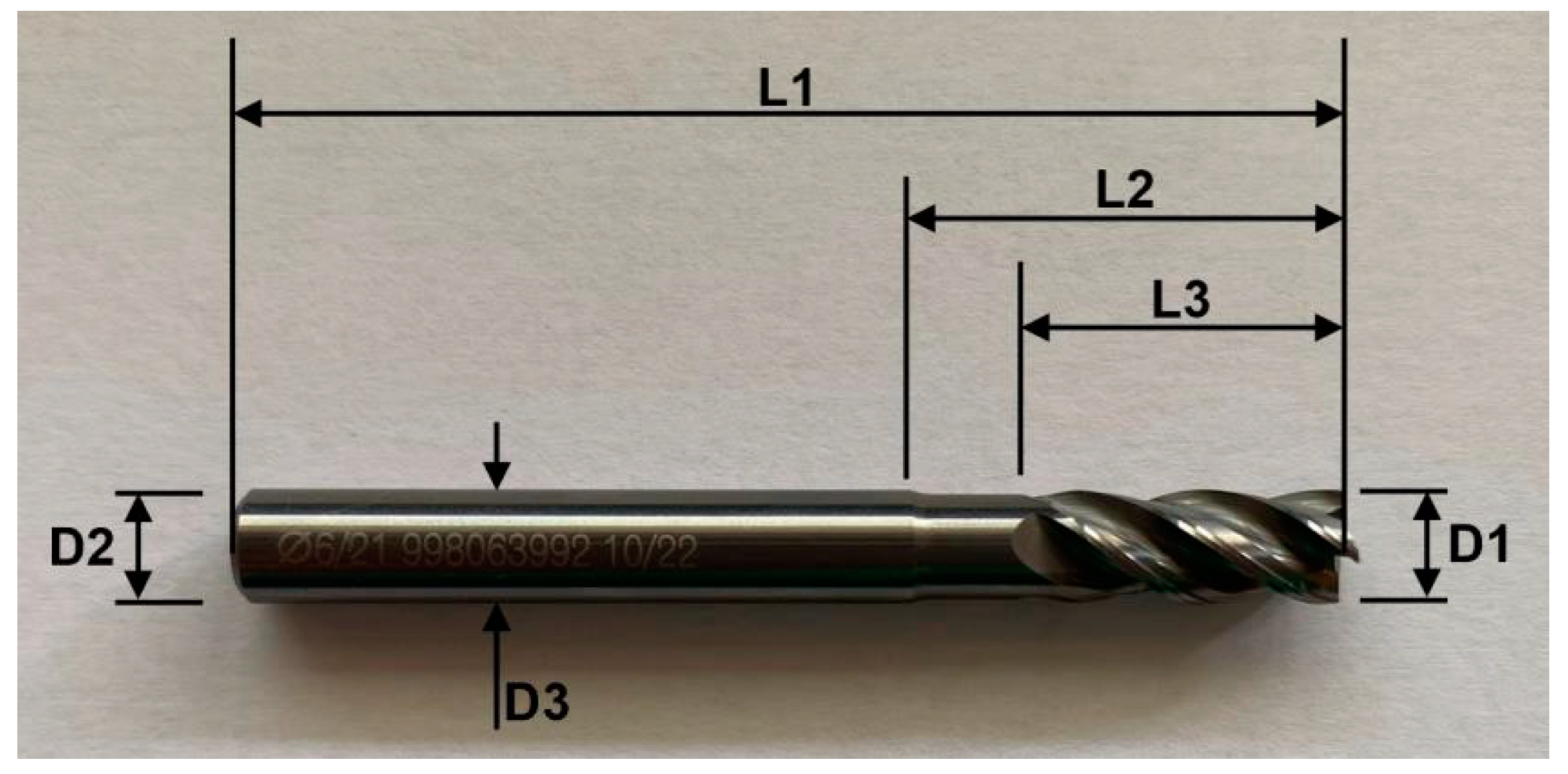
| Ref. | D1 | D2 | D3 | L1 | L2 | L3 | z |
|---|---|---|---|---|---|---|---|
| 288.060.00 | 6.00 | 6.00 | 5.50 | 57 | 13 | 21 | 4 |
| Property | Value | Units |
|---|---|---|
| Max. rpm | 18,000 | rpm |
| Pmax | 54.4 | kW |
| X-axis max. range | 600 | mm |
| Y-axis max. range | 500 | mm |
| Z-axis max. range | 500 | mm |
| No. of axes | 5 |
| Tool Reference | Coated | s (rpm) | f (mm/min) | Lcut (m) | Cooling |
|---|---|---|---|---|---|
| T0L27F750S126 | No | 126 | 750 | 26.8 | Yes |
| T0L54F750S126 | 750 | 53.6 | |||
| T0L74F750S126 | 750 | 73.7 | |||
| T0L27F1500S126 | 1500 | 26.8 | |||
| T0L54F1500S126 | 1500 | 53.6 | |||
| T0L74F1500S126 | 1500 | 73.7 | |||
| T1L27F750S126 | Yes | 750 | 26.8 | ||
| T1L54F750S126 | 750 | 53.6 | |||
| T1L74F750S126 | 750 | 73.7 | |||
| T1L27F1500S126 | 1500 | 26.8 | |||
| T1L54F1500S126 | 1500 | 53.6 | |||
| T1L74F1500S126 | 1500 | 73.7 |
| Tools Reference | Coated | Ra (μm) | Rz (μm) | Rt (μm) |
|---|---|---|---|---|
| T0L27F750S126 | No | 0.370 ± 0.047 | 1.992 ± 0.199 | 3.542 ± 0.600 |
| T0L54F750S126 | 0.428 ± 0.016 | 1.992 ± 0.178 | 3.576 ± 0.537 | |
| T0L74F750S126 | 0.470 ± 0.022 | 2.228 ± 0.109 | 3.654 ± 0.552 | |
| T0L27F1500S126 | 0.747 ± 0.031 | 3.410 ± 0.487 | 6.194 ± 0.893 | |
| T0L54F1500S126 | 0.780 ± 0.092 | 3.468 ± 0.249 | 6.194 ± 0.372 | |
| T0L74F1500S126 | 0.812 ± 0.040 | 4.152 ± 0.479 | 7.146 ± 0.656 | |
| T1L27F750S126 | Yes | 0.453 ± 0.035 | 2.264 ± 0.308 | 3.108 ± 0.692 |
| T1L54F750S126 | 0.484 ± 0.019 | 2.334 ± 0.324 | 3.992 ± 1.059 | |
| T1L74F750S126 | 0.584 ± 0.055 | 3.120 ± 0.164 | 4.192 ± 0.557 | |
| T1L27F1500S126 | 0.816 ± 0.063 | 4.136 ± 0.267 | 5.054 ± 0.772 | |
| T1L54F1500S126 | 0.940 ± 0.036 | 4.834 ± 0.438 | 6.872 ± 1.057 | |
| T1L74F1500S126 | 1.092 ± 0.084 | 5.256 ± 0.362 | 7.078 ± 0.585 |
| Tools Reference | Coated | Ra (μm) | Rz (μm) | Rt (μm) |
|---|---|---|---|---|
| T0L27F750S126 | No | 0.248 ± 0.035 | 1.502 ± 0.205 | 1.660 ± 0.196 |
| T0L54F750S126 | 0.266 ± 0.055 | 1.614 ± 0.262 | 2.088 ± 0.256 | |
| T0L74F750S126 | 0.360 ± 0.017 | 1.926 ± 0.662 | 2.090 ± 0.931 | |
| T0L27F1500S126 | 0.363 ± 0.016 | 2.066 ± 1.099 | 2.440 ± 1.268 | |
| T0L54F1500S126 | 0.384 ± 0.050 | 2.192 ± 0.278 | 2.490 ± 0.240 | |
| T0L74F1500S126 | 0.432 ± 0.060 | 2.654 ± 0.452 | 2.962 ± 0.553 | |
| T1L27F750S126 | Yes | 0.175 ± 0.050 | 1.404 ± 0.582 | 1.574 ± 1.127 |
| T1L54F750S126 | 0.334 ± 0.012 | 1.790 ± 0.305 | 1.938 ± 0.295 | |
| T1L74F750S126 | 0.496 ± 0.039 | 2.540 ± 0.709 | 3.230 ± 0.728 | |
| T1L27F1500S126 | 0.799 ± 0.079 | 4.488 ± 0.477 | 4.710 ± 0.674 | |
| T1L54F1500S126 | 1.054 ± 0.027 | 4.532 ± 0.802 | 4.742 ± 1.753 | |
| T1L74F1500S126 | 1.347 ± 0.097 | 4.784 ± 1.522 | 6.060 ± 1.555 |
| Tool Reference | Coated | VB (μm) |
|---|---|---|
| T0L27F750S126 | No | 10.674 ± 0.984 |
| T0L54F750S126 | 14.244 ± 0.085 | |
| T0L74F750S126 | 122.54 ± 0.974 | |
| T1L27F750S126 | Yes | 68.612 ± 1.820 |
| T1L54F750S126 | 98.876 ± 1.295 | |
| T1L74F750S126 | 132.81 ± 1.685 |
| Tool Reference | Coated | VB (μm) |
|---|---|---|
| T0L27F1500S126 | No | 59.792 ± 1.830 |
| T0L54F1500S126 | 103.784 ± 3.474 | |
| T0L74F1500S126 | 141.958 ± 2.779 | |
| T1L27F1500S126 | Yes | 82.802 ± 2.297 |
| T1L54F1500S126 | 121.252 ± 0.965 | |
| T1L74F1500S126 | 145.814 ± 0.914 |
| Tool Reference | Coated | Abrasion | Adhesion | Chipping | Microchipping | Delamination | Cracking |
|---|---|---|---|---|---|---|---|
| T0L27F750S126 | No | 5 | 4 | 3 | 4 | 1 | 1 |
| T0L54F750S126 | 5 | 4 | 3 | 3 | 1 | 3 | |
| T0L74F750S126 | 5 | 3 | 3 | 1 | 1 | 1 | |
| T0L27F1500S126 | 4 | 3 | 3 | 1 | 1 | 1 | |
| T0L54F1500S126 | 5 | 2 | 4 | 3 | 1 | 1 | |
| T0L74F1500S126 | 5 | 2 | 3 | 1 | 1 | 3 | |
| T1L27F750S126 | Yes | 3 | 3 | 5 | 1 | 5 | 4 |
| T1L54F750S126 | 3 | 3 | 4 | 1 | 5 | 1 | |
| T1L74F750S126 | 4 | 3 | 5 | 1 | 5 | 4 | |
| T1L27F1500S126 | 4 | 3 | 3 | 1 | 5 | 1 | |
| T1L54F1500S126 | 3 | 3 | 5 | 1 | 5 | 5 | |
| T1L74F1500S126 | 4 | 3 | 3 | 1 | 5 | 1 |
Disclaimer/Publisher’s Note: The statements, opinions and data contained in all publications are solely those of the individual author(s) and contributor(s) and not of MDPI and/or the editor(s). MDPI and/or the editor(s) disclaim responsibility for any injury to people or property resulting from any ideas, methods, instructions or products referred to in the content. |
© 2023 by the authors. Licensee MDPI, Basel, Switzerland. This article is an open access article distributed under the terms and conditions of the Creative Commons Attribution (CC BY) license (https://creativecommons.org/licenses/by/4.0/).
Share and Cite
Nogueira, F.R.; Pedroso, A.F.V.; Silva, F.J.G.; Campilho, R.D.S.G.; Sales-Contini, R.C.M.; Sebbe, N.P.V.; Casais, R.C.B. A Comparative Study on the Wear Mechanisms of Uncoated and TiAlTaN-Coated Tools Used in Machining AMPCO® Alloy. Coatings 2024, 14, 4. https://doi.org/10.3390/coatings14010004
Nogueira FR, Pedroso AFV, Silva FJG, Campilho RDSG, Sales-Contini RCM, Sebbe NPV, Casais RCB. A Comparative Study on the Wear Mechanisms of Uncoated and TiAlTaN-Coated Tools Used in Machining AMPCO® Alloy. Coatings. 2024; 14(1):4. https://doi.org/10.3390/coatings14010004
Chicago/Turabian StyleNogueira, Francisca R., André F. V. Pedroso, Francisco J. G. Silva, Raul D. S. G. Campilho, Rita C. M. Sales-Contini, Naiara P. V. Sebbe, and Rafaela C. B. Casais. 2024. "A Comparative Study on the Wear Mechanisms of Uncoated and TiAlTaN-Coated Tools Used in Machining AMPCO® Alloy" Coatings 14, no. 1: 4. https://doi.org/10.3390/coatings14010004
APA StyleNogueira, F. R., Pedroso, A. F. V., Silva, F. J. G., Campilho, R. D. S. G., Sales-Contini, R. C. M., Sebbe, N. P. V., & Casais, R. C. B. (2024). A Comparative Study on the Wear Mechanisms of Uncoated and TiAlTaN-Coated Tools Used in Machining AMPCO® Alloy. Coatings, 14(1), 4. https://doi.org/10.3390/coatings14010004