Article

Study on the Wear Performance of Surface Alloy Coating of Inner Lining Pipe under Different Load and Mineralization Conditions

by
Yuntao Xi
1,2,*,
Yucong Bi
1,
Yang Wang
3,
Lan Wang
3,
Shikai Su
4,
Lei Wang
1,5,6,7,8,*,
Liqin Ding
9,
Shanna Xu
1,
Haitao Liu
5,
Xinke Xiao
7,
Ruifan Liu
4 and
Jiangtao Ji
10
1
School of Material Science and Engineering, Xi’an Shiyou University, Xi’an 710065, China
2
National Subsea Centre, Robert Gordon University, Aberdeen AB21 0BH, UK
3
No. 7 Oil Production Plant of Changqing Oilfield Company, Qingcheng 717600, China
4
Shaanxi Coal Industry New Energy Technology Co., Ltd., Xi’an 710199, China
5
State Key Laboratory of Rolling and Automation, Northeastern University, Shenyang 110819, China
6
State Key Laboratory of Tribology in Advanced Equipment, Tsinghua University, Beijing 100084, China
7
Henan International Joint Laboratory of Dynamics of Impact and Disaster of Engineering Structures, Nanyang Institute of Technology, Nanyang 473004, China
8
State Key Laboratory for Mechanical Behavior of Materials, Xian Jiaotong University, Xi’an 710049, China
9
College of Chemistry & Chemical Engineering, Xi’an Shiyou University, Xi’an 710065, China
10
China Railway First Survey and Design Institute Group Co., Ltd., Xi’an 710043, China
*
Authors to whom correspondence should be addressed.
Coatings 2024, 14(10), 1274; https://doi.org/10.3390/coatings14101274
Submission received: 9 August 2024 / Revised: 25 September 2024 / Accepted: 1 October 2024 / Published: 4 October 2024

Abstract

:
Testing was carried out in this study to evaluate the friction and wear performance of 45# steel inner liner pipes with cladding, along with four different types of centralizing materials (45# steel, nylon, polytetrafluoroethylene (PTFE), and surface alloy coating) in oil field conditions. Under dry-friction conditions, the coefficients of friction and rates of wear are significantly higher than their counterparts in aqueous solutions. This is attributed to the lubricating effect provided by the aqueous solution, which reduces direct friction between contact surfaces, thereby lowering wear. As the degree of mineralization in the aqueous solution increases, the coefficient of friction tends to decrease, indicating that an elevated level of mineralization enhances the lubricating properties of the aqueous solution. The wear pattern in an aqueous solution is similar to that in dry-friction conditions under different loads, but with a lower friction coefficient and wear rate. The coating has played an important role in protecting the wear process of 45# steel, and the friction coefficient and wear rate of tubing materials under various environmental media have been significantly reduced. In terms of test load, taking into account the friction coefficient and wear rate, the suggested order for centralizing materials for lining oil pipes with the surface alloy coating is as follows: (i) surface alloy coating, (ii) nylon, (iii) PTFE, and (iv) 45# steel.

1. Introduction

In many reservoirs around the world, downhole pressure cannot lift the produced fluid to the surface. When conducting oil production in these areas, a pump is used to lift the fluid manually. This method is called artificial lifting. Currently, more than 70 percent of all wells are being produced by artificial lift methods. The rod pump is one of the most widely used artificial lifting methods at present. Due to the ease of implementation, rod pumps are considered a mature technology in the oil and gas industry, so they are relatively common worldwide, and have low capital and operating costs [1].
The rod pumping system is one of the most widely used pumping methods domestically and abroad. The friction and wear between the rod and tubing have always been an important problem to be solved in the stable operation of the rod pumping system. It will indirectly cause all kinds of underground accidents, increase the maintenance times and maintenance costs of oil wells, and directly affect the production efficiency of oil wells. To address the issue of friction and wear between the sucker rod and tubing in rod pump systems, common practises include the application of surface alloy coatings, the optimization of design to mitigate eccentric wear, the introduction of solid or liquid lubricants to reduce the coefficient of friction, and the installation of tubing centralizers to minimize direct contact between the rod and the tubing wall. Numerous scholars have carried out substantial theoretical research on the eccentric wear of sucker rod tubes [2,3,4,5,6,7] and have achieved certain results. It is a common method to install a centralizer on the rod string in oil fields, which is low-cost and has a competitive effect. The rod centralizer is extremely effective in reducing the impact of rod and tubing wear, increasing the service life of the rod and tubing, and reducing the maintenance frequency and production costs [8,9,10].
Although the centralizer has the above advantages, friction will inevitably occur between the centralizer and the inner wall of the tubing. A certain number of researchers have studied the quality of centralizing materials and tubing coatings. However, due to the difference in well condition, working system, and oil production depth in each oil production block, the effect of anti-deflection wear measures is extremely different, and it is not universally applicable [11,12,13,14]. In order to achieve this, this study performed wear testing on matching pairs consisting of cladding oil pipe material and four different types of centralizer materials (45# steel, nylon, polytetrafluoroethylene (PTFE), and surface alloy coating) under both dry-friction and salinity water lubrication conditions. Meanwhile, the wear mechanism was analyzed to reveal the friction and wear rules. Finally, the best centralizer materials were recommended [15,16,17]. This study provides the basis for the theoretical model modification and the selection of anti-wear material on-site, and effectively improves the service life of the centralizer and tubing.

2. Experimental Section

2.1. Materials

The material used for the tubing in this experiment was cladded 45# steel. Thermal spraying is an efficient surface alloy coating technique that involves heating alloy materials to a molten or semi-molten state and propelling them at high velocity onto the substrate surface to form a robust coating. This method enables rapid deposition and provides protective layers that are wear-resistant, corrosion-resistant, and oxidation-resistant. The reasons for selecting thermal spraying include its ability for rapid deposition, controllable coating thickness, strong adhesion to the substrate, cost-effectiveness, and adaptability under various environmental conditions. Various centralizing materials, including 45# steel, nylon, PTFE, and surface alloy coatings, were tested, and their respective parameters are detailed in Table 1. The surface alloy coating was a nickel-based alloy, while the cladded coating predominantly comprised elements such as W, O, Ni, C, and P, with the coating primarily consisting of WC, WO3, Ni2O3, and Ni. The thickness of the cladded coating was 1 mm, and the surface roughness Ra of the cladded coating was 1.6 microns. Hardness is a key measure of a material’s resistance to plastic deformation caused by external indentation. In most cases, there is a direct relationship between hardness and flow stress; as the micro-hardness testing indenter is small, it can be used to measure the hardness of materials in different regions or stages. These results can then be used as a basis for analyzing microstructure characteristics. The Rockwell hardness of 45# steel is 60, that for cladded coating materials is 72, and the Shore hardness of nylon, polyethylene, and PTFE are 80, 66, and 60, respectively.

2.2. Experimental Procedure

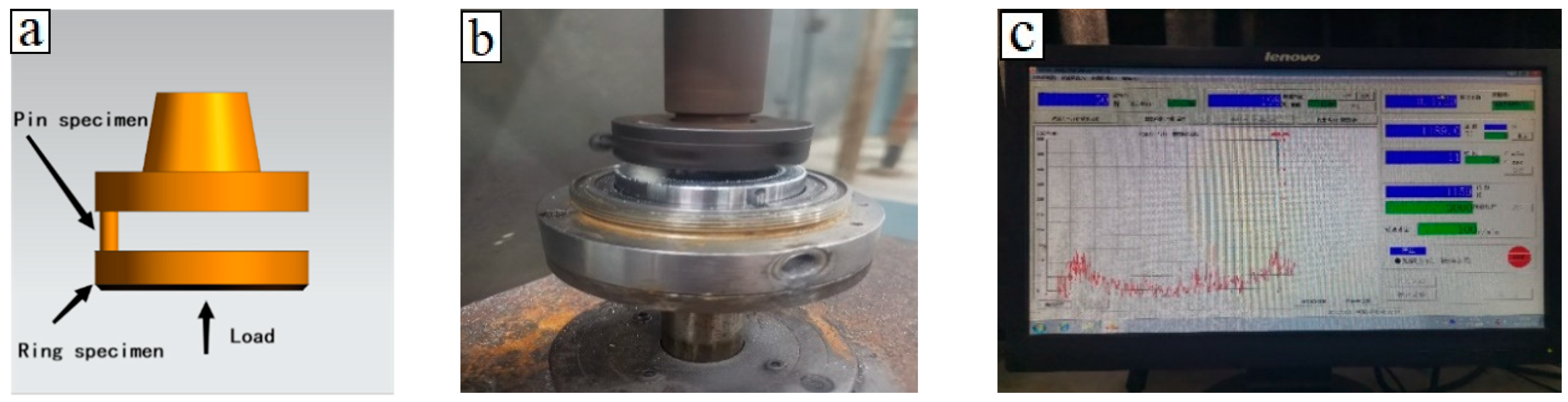
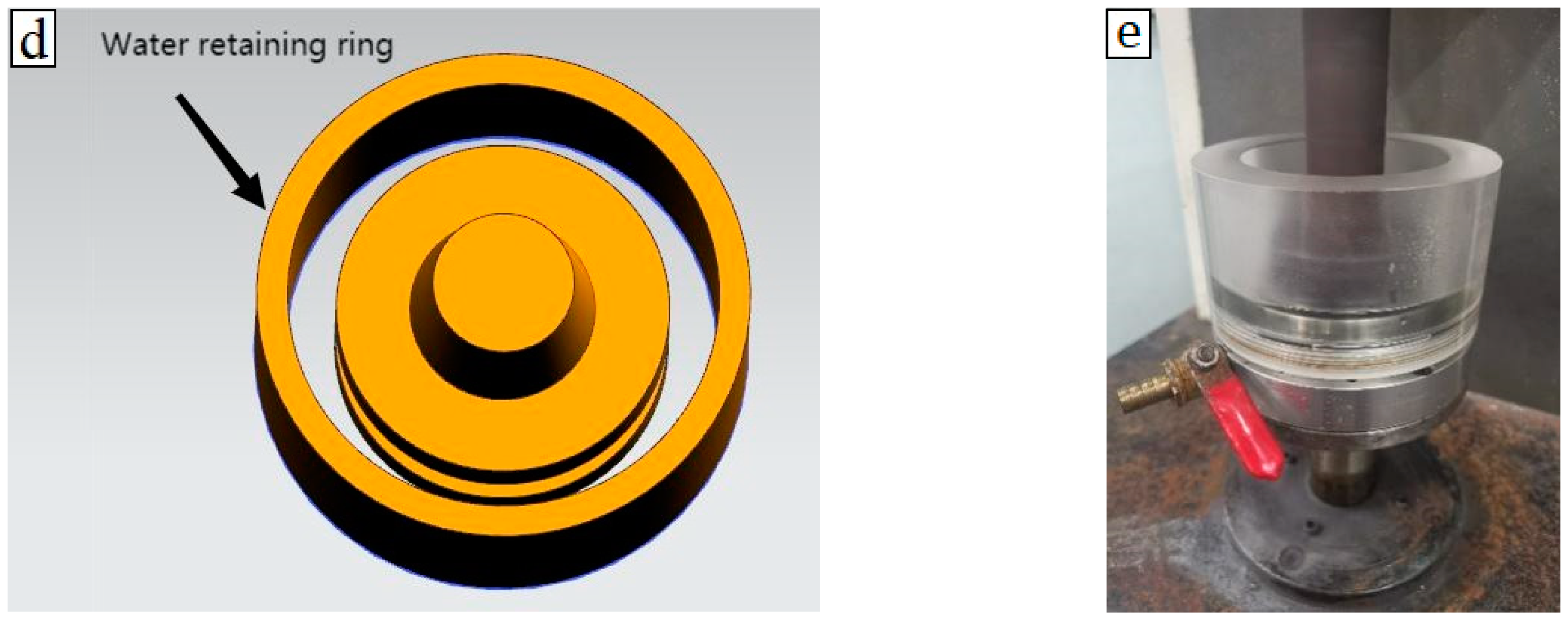
2.2.1. Friction and Wear Experiment

The pin disc friction and wear test is a method for assessing the friction and wear characteristics of various materials, including lubricants, metals, plastics, coatings, rubber, and ceramics. It involves evaluating both point-to-surface and surface-to-surface contact friction. The testing is conducted in accordance with the ASTMG99-2017 standard. Figure 1a–c illustrate the schematic and physical diagrams of the pin disc friction and wear testing device. In this experimental setup, a disc is fabricated from oil pipe material and a pin is created from centering material to simulate a disc–pin-type friction and wear test [18,19].
In order to determine the wear test duration, initial experiments were carried out with selected sets of metal–non-metal and metal–metal friction pairs, comparing wear test times of 30 min and 60 min. The experiments revealed that the friction coefficient tended to stabilize after 20 min of wear, with negligible changes observed after 30 min. The rotational speed had minimal impact, with little variation in the friction and wear curves under test conditions of 100 r/min and 200 r/min. Therefore, based on these results, the wear test conditions were established as follows: a 30 min wear test duration and a friction speed of 100 r/min. To ensure the repeatability of the experimental data, three parallel experiments were conducted for each set of friction and wear tests.
The degree of mineralization in the extracted water has a specific impact on friction and wear performance. In order to understand this relationship, the experiment also involved conducting friction and wear tests at varying levels of mineralization for each stabilizing material. Water mineralization refers to the phenomenon where water contains mineral elements due to the dissolution of certain amounts of inorganic salts, such as calcium, magnesium, sodium, and potassium. The degree of water mineralization can be assessed by measuring the total dissolved solids (TDS) in the water. To facilitate the friction and wear experiments at different mineralization levels in an aqueous solution environment, this study designed and fabricated an organic glass container, as depicted in Figure 1d,e.

2.2.2. Scanning Electron Microscope

The microstructure of the worn pins and discs was analyzed using a scanning electron microscope (SEM) equipped with a field emission gun (Model: JSM-7001F, JEOL, Tokyo, Japan) operated at 20 kV. The SEM produces image contrast based on variations in the micro-area characteristics of the sample surface, including morphology, atomic number or chemical composition, and crystal structure or orientation. These variations generate physical signals of different intensities under the electron beam, resulting in distinct brightness differences on the fluorescent screen of the cathode ray tube and allowing for the capture of images with specific contrast [20,21].

2.2.3. Three-Dimensional Confocal Microscopy Analysis

The VHX-600E, a three-dimensional confocal microscope (Keyence, Osaka, Japan), is utilized for analyzing the surface physical characteristics and conducting wear morphology assessments at micro- and nanoscales. This includes studying 3D surface morphology and 2D depth morphology, as well as analyzing contours such as depth, width, curvature, and angle, along with surface roughness measurements.

3. Results

3.1. The Influence of Different Environmental Media on Wear Performance

Tests were carried out on cladded 45# steel inner liner pipes and different centralizing materials in aqueous solutions with varying levels of mineralization, under a 150 N load, to study friction and wear. The results detailing the friction coefficients for each material are presented in Table 2, and the friction coefficient curve is illustrated in Figure 2a–d. It was observed that the friction coefficient of the centralizing materials exhibited noticeable variations with the degree of mineralization for the cladded 45# steel inner liner pipes. The friction coefficient of the centralizing materials under dry friction is relatively highest. With the increase in the mineralization degree of the aqueous solution, the friction coefficient generally shows a downward trend, and the friction coefficient is about 20% of the dry-friction environment.
This study calculates the wear rate per hundred kilometres to represent the volume lost during the wear test of the straightening material and tubing material. Table 2 presents the wear rates of the centralizing material and the tubing material per hundred kilometres in aqueous solutions with varying degrees of mineralization, and their changing trends are depicted in Figure 2f,g. The low wear rate of the tubing material under different centralizing materials suggests that the coating can effectively contribute to reducing wear, leading to a significantly increased service life. The wear rate of friction pairs composed of cladded 45# steel inner liner pipes and centralizing materials in an aqueous solution environment has little change and is slightly lower than that in a dry-friction environment. In terms of mineralization, when taking into account factors such as friction coefficient and wear rate, the suggested order for centralizing materials for surface-alloy-coating-lined oil pipes is as follows: (1) nylon, (2) surface alloy coating, (3) PTFE, and (4) 45# steel.

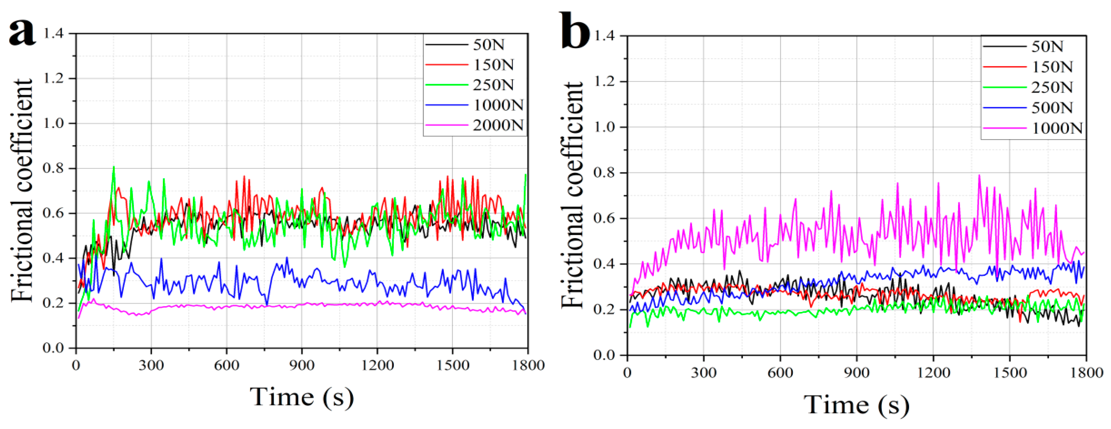
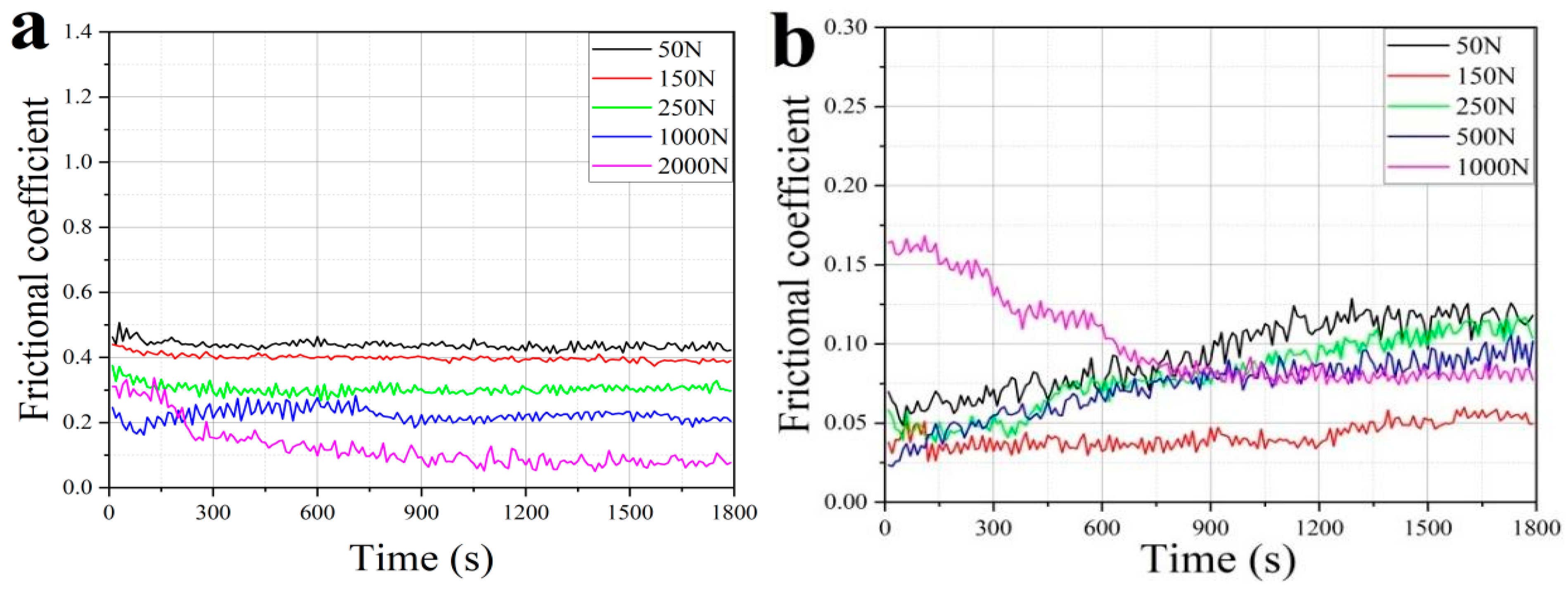
3.2. The Influence of Different Test Loads on Wear Performance

3.2.1. Under Dry-Friction Conditions

Figure 3a–d display the friction and wear test curves for cladded 45# steel inner liner pipes under varying loads, while Table 3 provides specific data on the friction coefficient. For cladded 45# steel inner liner pipes, the friction coefficient of the centralizing materials changes obviously with the applied load. As the applied load increases, the friction coefficient of the frictional pairs and the coupling decreases.
Table 3 also provides the wear rates of centralizing materials and tubing materials per 100 km under various dry-friction load conditions, while Figure 3f,g illustrate the trends in their changes. For cladded 45# steel inner liner pipes, the wear rate of centralizing materials increases with the increase in load, among which the wear rate of PTFE is largest and the service life is shortest. Its service life is about 1/10 of the rest of the centralizing materials. On the other hand, when cladded 45# steel inner liner pipes are paired with 45# steel and nylon, the wear rate of the tubing is highest and the service life is shortest. When paired with PTFE and the surface alloy coating, the wear rate of the tubing is lower and the service life is longer. When considering the factors of friction coefficient and wear rate, the recommended sequence for stabilizing materials for lining oil pipes with the surface alloy coating is as follows, (1) surface alloy coating, (2) nylon, (3) PTFE, and (4) 45# steel, from the perspective of test load.

3.2.2. Under Aqueous Solution Environment

In order to thoroughly evaluate how the level of mineralization and the amount of applied load impact the friction and wear characteristics of cladded 45# steel inner liner pipes, this research conducted tests to measure the friction and wear performance under various loads in a 30,000 mg/L mineralization-degree aqueous solution. The friction coefficient curve is depicted in Figure 4, and the specific friction coefficients are detailed in Table 4. For cladded 45# steel inner liner pipes, the friction coefficient of the centralizing materials changes obviously with the applied load. The friction coefficient of metal material decreases with the increase in applied load. There is little change in the friction coefficient of non-metallic centralizing materials as the applied load increases.
Table 4 provides the wear rates of centralizing materials and tubing materials per 100 km in a 30,000 mg/L mineralization-degree aqueous solution under various load conditions, with the changing trends depicted in Figure 4f,g. For cladded 45# steel inner liner pipes, the wear rate of the centralizing materials increases with the increase in load, among which the wear rate of PTFE is largest and the service life is shortest. Similar to dry-friction conditions, when the friction pair is formed with the centralizing materials, the wear rate of the tubing material increases with the increase in the load, of which the wear rate of the tubing is largest and the service life is shortest when it is formed with 45# steel. Conversely, when paired with PTFE and the surface alloy coating, the wear rate of the tubing is minimal and the service life is longer. In terms of testing the load and taking into account factors such as friction coefficient and wear rate, the suggested order for centralizing materials for lining oil pipes with surface alloy coatings is as follows: (1) surface alloy coating, (2) nylon, (3) PTFE, and (4) 45# steel.

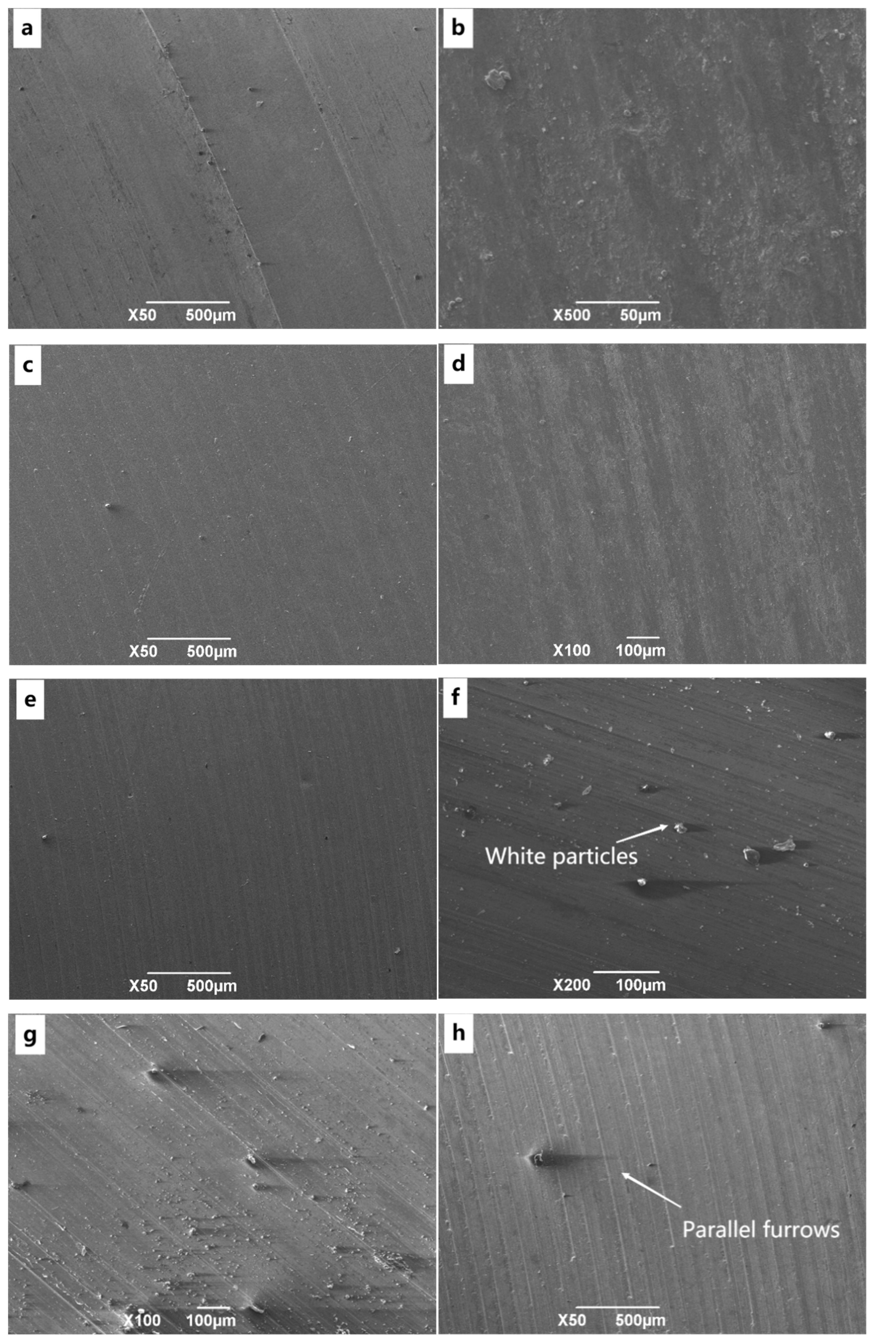
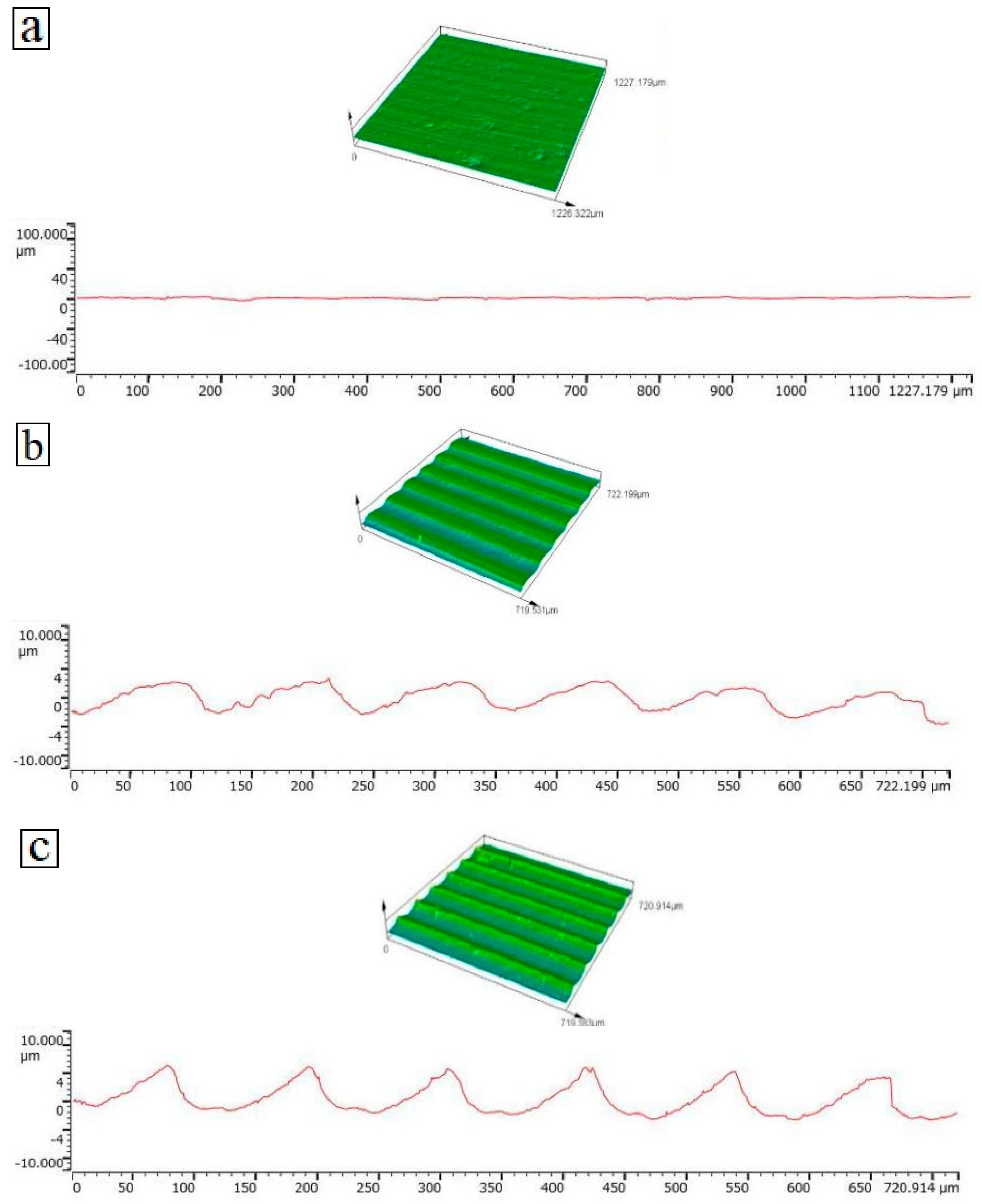
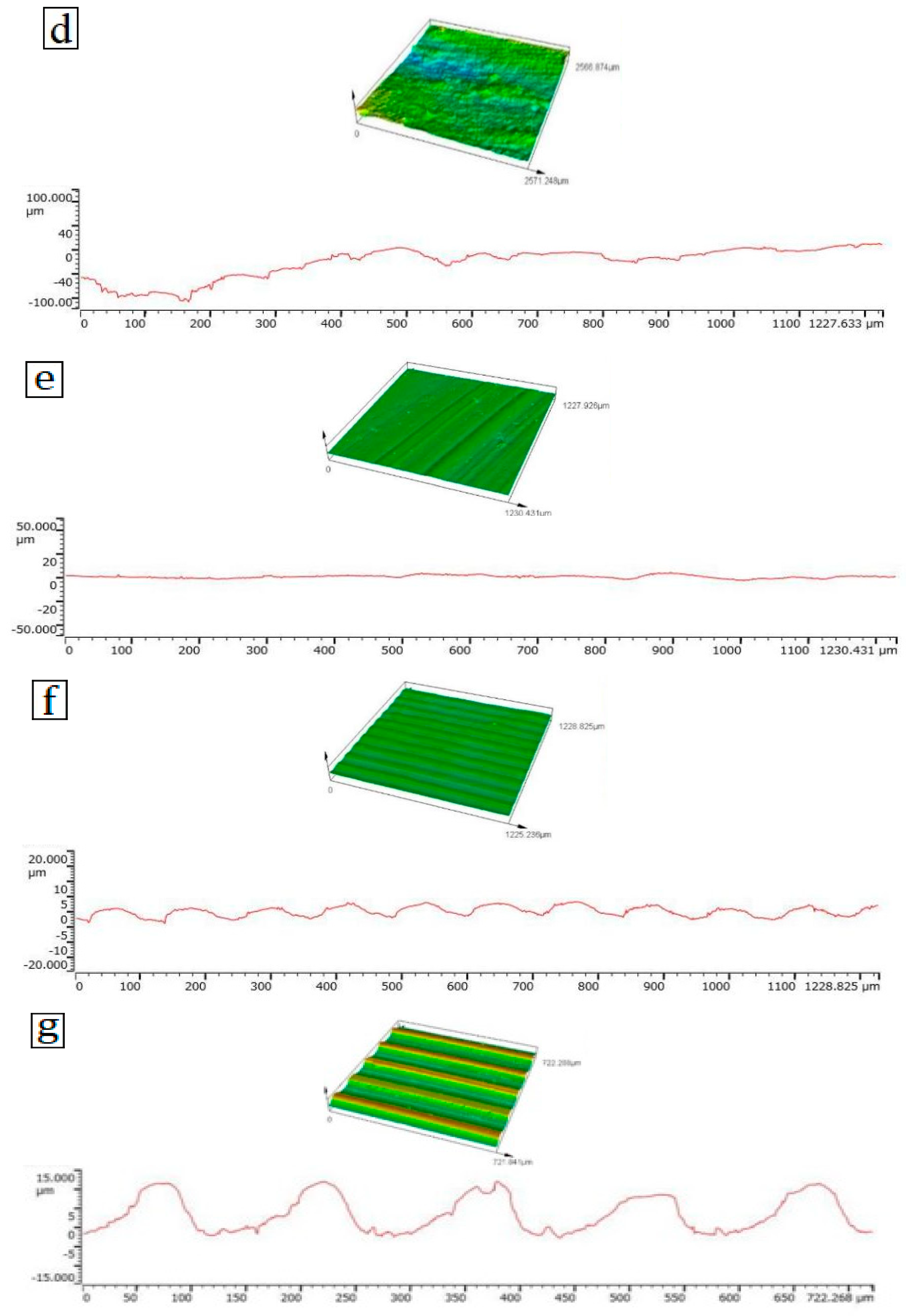
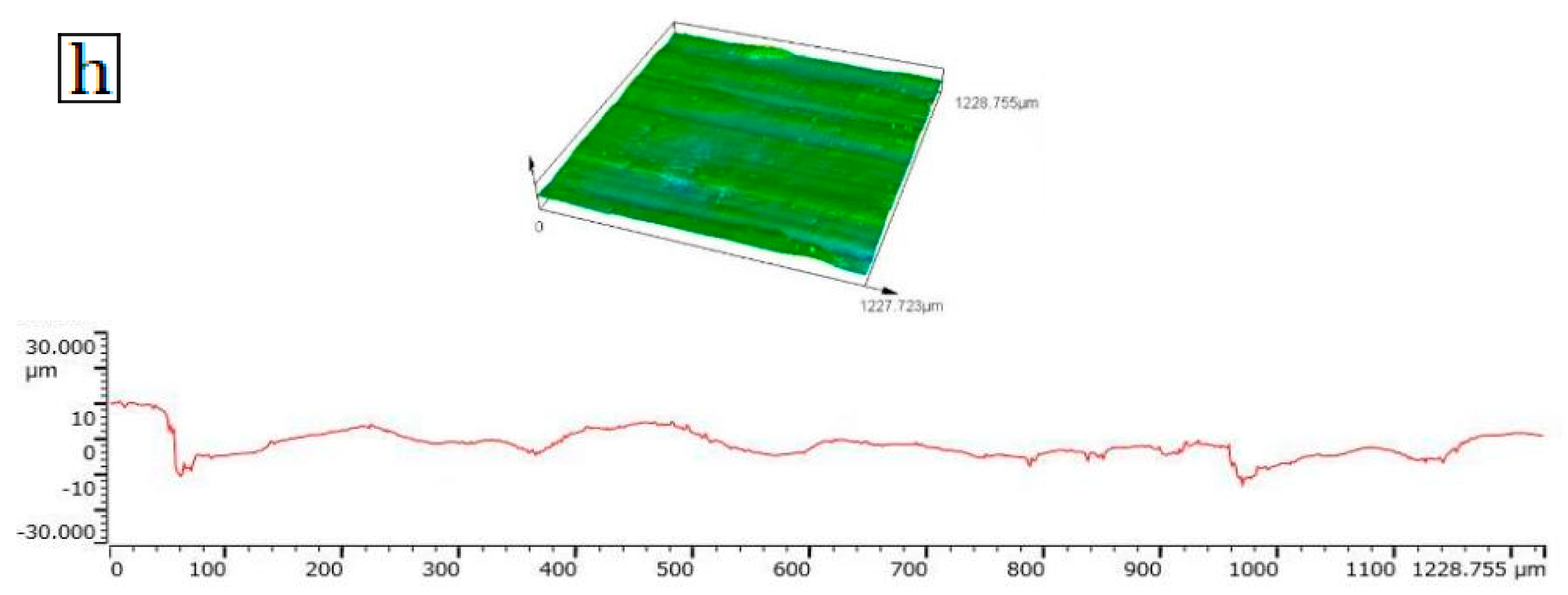
3.3. Analysis of Wear Mechanism

The test results above indicate that the cladded 45# steel inner liner pipes and four types of centralizing materials (45# steel, nylon, PTFE, surface alloy coating) exhibit lower friction coefficients under varying loads and in different mineralized aqueous solutions. To elucidate the wear mechanism of this low-friction-coefficient pair, SEM analysis and three-dimensional confocal microscopy analysis were conducted on the cladded 45# steel inner liner pipes (disc)–PTFE (pin) pair under different loads in a 30,000 mg/L degree-of-mineralization aqueous solution. The findings are presented in Figure 5 and Figure 6.
Examination of the surface SEM microstructure of the disc and pin that have undergone wear reveals that the friction coefficient of the cladded 45# steel inner liner pipes (disc) and PTFE (pin) friction pair is comparatively low, making it a recommended choice for a friction pair. The wear surface is flat and slightly worn, with only some fine furrows and a few cracks. The confocal experiment in three dimensions reveals clear ridges with consistent and small gaps across different levels of pressure. The surface also displays shallow signs of wear, including pits and white particles. It is presumed that the metal alloy on the surface of the upper specimen is forced out due to adhesive wear, hard metal oxide particles are formed to adhere to the surface of the lower specimen, and wear marks are generated on the surface of the upper specimen during cross-grinding. This is typical fatigue wear [22,23,24].
Lubricated with aqueous, the friction coefficient of PTFE is lower than that in the dry-friction condition. This is due to the low viscosity of water and the fact that the formed hydrodynamic pressure water film is thinner, which is not enough to completely separate the contact of the friction pair material [25,26,27,28]. However, it can play a certain bearing and boundary lubrication role, thereby reducing the friction coefficient. During dry friction, a large amount of friction heat causes the surface temperature of the sample to rise sharply, resulting in the strength of the subsurface layer decreasing [29,30], plastic deformation occurring, and the surface layer spalling, so the wear is larger. When the oil well is lubricated by the water produced, most of the friction heat is carried away by the water, the temperature of the friction surface is limited, and the strength changes little [31]. In this case, the shear force is not enough to cause obvious plastic deformation, so the wear amount is small.

4. Conclusions

During this experiment, we conducted tests to analyze the friction and wear performance of four different centralizing materials for cladded 45# steel inner liner pipes. These tests were carried out under varying mineralization degrees and load conditions. The analysis focused on the friction coefficient, wear rate, and wear mechanism under these different conditions. The key findings and conclusions are as follows:
By comparing the experimental data in Table 3 and Table 4, it can be found that under the same load conditions, dry friction demonstrates a noticeably higher friction coefficient and wear rate compared to an aqueous solution. The wear behavior under varying loads in an aqueous solution is similar to that in a dry-friction environment, but the friction coefficient and wear rate are lower than those seen in dry-friction situations. The lubricating effect provided by the aqueous solution reduces direct friction between contact surfaces, thereby reducing wear. As the degree of mineralization in the aqueous solution increases, the coefficient of friction tends to decrease, indicating that an elevated level of mineralization enhances the lubricating properties of the aqueous solution. Further exploration of the wear mechanism of low-friction-coefficient pairs was conducted using scanning electron microscopy (SEM) and three-dimensional confocal microscopy analysis. The analysis revealed that the wear surface of the 45#-steel-lined pipe paired with PTFE is relatively flat, with only some fine grooves and a few cracks. This suggests that in the aqueous solution environment, the adhesive wear and fatigue wear phenomena during the wear process are mitigated due to the lubricating action of water. Under dry-friction conditions, the generation of frictional heat causes a sharp rise in the surface temperature of the samples, leading to a decrease in the strength of the subsurface layer, resulting in plastic deformation and spalling of the surface layer, thus increasing wear. In contrast, in oil wells lubricated by the produced water, most of the frictional heat is carried away by the water, limiting the temperature of the friction surface and maintaining the strength with minimal change. At this point, the shear force is not sufficient to cause significant plastic deformation; hence, the wear amount is smaller.
Cladded coatings play an important role in protecting the wear process of 45# steel, so the friction coefficient and wear rate of tubing materials under a variety of environmental media are significantly reduced. For example, the friction coefficient and wear rate of the cladded 45# steel inner liner pipes–surface alloy coating (pin) pair are significantly reduced compared to other pairs in various environmental media.
In terms of test load, taking into account the friction coefficient and wear rate, the suggested order for centralizing materials for lining oil pipes with surface alloy coatings is as follows: (i) surface alloy coating, (ii) nylon, (iii) PTFE, and (iv) 45# steel.

Author Contributions

Methodology, H.L. and X.X.; Investigation, Y.B., Y.W., S.S., S.X., R.L. and J.J.; Resources, Y.X. and L.D.; Data curation, L.W. (Lan Wang); Writing—original draft, L.W. (Lei Wang). All authors have read and agreed to the published version of the manuscript.

Funding

The present work has been financially supported by the National Natural Science Foundation of China Project (Grant No.: 12102340); Youth Innovation team construction in Shaanxi Universities (Shaanxi teaching letter 2023-997-29); the Young Scientific Research and Innovation Team of Xi’an Shiyou University (Grant No.: 2019QNKYCXTD14); The Open Research Fund from the State Key Laboratory of Rolling and Automation, Northeastern University (Grant No.: 2022RALKFKT009); The Tribology Science Fund of State Key Laboratory of Tribology in Advanced Equipment (Grant No.: SKLTKF22B10); the Henan International Joint Laboratory of Dynamics of Impact and Disaster of Engineering Structures, Nanyang Institute of Technology (Grant No.: LDIDES-KF2022-02-02); the State Key Laboratory for Mechanical Behavior of Materials (Grant No.: 20242605); the Open Foundation of Shaanxi Key Laboratory of Carbon Dioxide Sequestration and Enhanced Oil Recovery (YJSYZX23SKF0007); the Natural Science Basic Research Program of Shaanxi Province (Program No. 2022JM-078); the China Scholarship Council Foundation (Grant No.: 202208615046); and the Postgraduate Innovation and Practical Ability Training Program of the Xi’an Shiyou University (Grant No.: YCX2413125).

Informed Consent Statement

Not applicable.

Data Availability Statement

The data in this paper are available upon reasonable request.

Conflicts of Interest

Yang Wang and Lan Wang are employed by No. 7 Oil Production Plant of Changqing Oilfield Company; Shikai Su and Ruifan Liu are employed by Shaanxi Coal Industry New Energy Technology Co., Ltd.; Jiangtao Ji is employed by China Railway First Survey and Design Institute Group Co., Ltd. The remaining authors declare that the research was conducted in the absence of any commercial or financial relationships that could be construed as a potential conflict of interest.

References

  1. Askari, M.; Aliofkhazraei, M.; Afroukhteh, S. A comprehensive review on internal corrosion and cracking of oil and gas pipelines. J. Nat. Gas Sci. Eng. 2019, 71, 102971. [Google Scholar] [CrossRef]
  2. Tao, R.; Nan, Z.J.; Wen, S.; Kang, X.Q. Analysis Method of Sucker Rod Centralizer Spacing in Three-Dimensional Hole; Atlantis Press: Dordrecht, The Netherlands, 2016; pp. 163–167. [Google Scholar]
  3. Trausmuth, A.; Kronberger, M.; Raghuram, H.; Rojacz, H.; Badisch, E.; Ripoll, M.R. Tribocorrosion performance of Fe-base and Ni-base wear resistant coatings in CO2 anoxic environments. Corros. Sci. 2022, 196, 110035. [Google Scholar] [CrossRef]
  4. Treiberg, T.; Furr, B. Wireless Sensor Technology to Monitor Rod Rotator Performance. In Proceedings of the SPE Artificial Lift Conference and Exhibition-Americas, Galveston, TX, USA, 20–24 August 2022. [Google Scholar]
  5. Zhang, Q.; Wang, X.L.; Wei, L.; Xiao, Z.M.; Yue, Q.B.; Zhu, Y. Buckling of a twisted rod with centralizers in a tubing. J. Pet. Sci. Eng. 2021, 204, 108731. [Google Scholar] [CrossRef]
  6. Carpenter, C. Fiberglass-Lined Tubing Helps Prevent Asphaltene Deposition in Oil Wells. J. Pet. Technol. 2021, 73, 55–56. [Google Scholar] [CrossRef]
  7. Langbauer, C.; Hartl, M.; Gall, S.; Volker, L.; Decker, C.; Koller, L.; Hönig, S. Development and Efficiency Testing of Sucker Rod Pump Downhole Desanders. SPE Prod. Oper. 2020, 35, 406–421. [Google Scholar] [CrossRef]
  8. Ye, K.X.; Li, F.; Jin, Z.; Chen, J.F.; Li, Z.L. Effect of SiO2 on microstructure and mechanical properties of composite ceramic coatings prepared by centrifugal-SHS process. Ceram. Int. 2021, 47, 12833–12842. [Google Scholar] [CrossRef]
  9. Edappillikulangara Chinnappan, R.; Telang, M.; Quttainah, R.; Radhakrishnan, G.; Fernandes, A.; Rajendran, K. First Time Worldwide Application of Glass Reinforced Epoxy Lined Tubing for Prevention of Asphaltene Deposition on Tubing in Oil Wells-A Case Study from Kuwait. In Proceedings of the International Petroleum Technology Conference, Virtual, 23–25 March 2021. [Google Scholar]
  10. Askari, M.; Aliofkhazraei, M.; Jafari, R.; Hamghalam, P.; Hajizadeh, A. Downhole corrosion inhibitors for oil and gas production-a review. Appl. Surf. Sci. Adv. 2021, 6, 100128. [Google Scholar] [CrossRef]
  11. Carpenter, C. High-Density Polyethylene Liner Safeguards against Corrosion and Wear. J. Pet. Technol. 2020, 72, 60–61. [Google Scholar] [CrossRef]
  12. Zhao, R.D.; Li, J.Y.; Tao, Z.; Liu, M.; Shi, J.F.; Xiong, C.M.; Huang, H.X.; Sun, C.Y.; Zhang, Y.F.; Zhang, X.W. Research and Application of Rod/Tubing Wearing Prediction and Anti-Wear Method in Sucker Rod Pumping Wells. In Proceedings of the SPE Middle East Oil and Gas Show and Conference, Manama, Bahrain, 18–21 March 2019. [Google Scholar]
  13. Sun, X.; Ji, X.; Li, W.; Zhang, L.; Song, Y. Dynamic Simulation Analysis of Carbon-Steel Hybrid Sucker Rod String in Vertical and Directional Wells. Math. Probl. Eng. 2022, 2022, e5239355. [Google Scholar] [CrossRef]
  14. Nickell, I.A. Surface Diagnostics and Analysis in Optimization Technologies for Sucker Rod Pump Lifted Oil and Gas Wells. In Proceedings of the SPE Artificial Lift Conference and Exhibition-Americas, Virtual, 12 November 2020. [Google Scholar]
  15. Langbauer, C.; Fruhwirth, R.K.; Volker, L. Sucker Rod Anti-Buckling System: Development and Field Application. SPE Prod. Oper. 2021, 36, 327–342. [Google Scholar]
  16. Moreno, G.A.; Garriz, A.E. Sucker rod string dynamics in deviated wells. J. Pet. Sci. Eng. 2020, 184, 106534. [Google Scholar] [CrossRef]
  17. Kang, Y.; Li, S.Y.; Zhang, K.Q.; Wang, Y.W. Synergy of hydrophilic nanoparticle and nonionic surfactant on stabilization of carbon dioxide-in-brine foams at elevated temperatures and extreme salinities. Fuel 2021, 288, 119624. [Google Scholar]
  18. Zhai, W.Y.; Pu, B.W.; Sun, L.; Wang, Y.R.; Dong, H.; Gao, Q.; He, L.; Gao, Y.M. Influence of molybdenum content and load on the tribological behaviors of in-situ Cr3C2-20 wt % Ni composites. J. Alloys Compd. 2020, 826, 154180. [Google Scholar] [CrossRef]
  19. Zhai, W.Y.; Pu, B.W.; Sun, L.; Dong, H.; Wang, Y.R.; He, L.; Gao, Y.M. Influence of Ni content on the microstructure and mechanical properties of chromium carbide-nickel composites. Ceram. Int. 2020, 46, 8754–8760. [Google Scholar] [CrossRef]
  20. Wang, L.; Benito, J.A.; Calvo, J.; Cabrera, J.M. Equal Channel Angular Pressing of a TWIP steel: Microstructure and mechanical response. J. Mater. Sci. 2017, 52, 6291–6309. [Google Scholar] [CrossRef]
  21. Wang, L.; Hao, X.Y.; Su, Q.; Jing, X.Q.; Xi, Y.T.; Lei, W.; Li, S.L.; Yang, D.Y.; Ji, J.T.; Lei, S.B. Ultrasonic Vibration-Assisted Surface Plastic Deformation of a CrCoNi Medium Entropy Alloy: Microstructure Evolution and Mechanical Response. JOM 2022, 74, 4202–4214. [Google Scholar] [CrossRef]
  22. Ligier, K.; Olejniczak, K.; Napiorkowski, J. Wear of polyethylene and polyurethane elastomers used for components working in natural abrasive environments. Polym. Test. 2021, 100, 107247. [Google Scholar] [CrossRef]
  23. Barber, H.; Kelly, C.N.; Abar, B.; Allen, N.; Adams, S.B.; Gall, K. Rotational Wear and Friction of Ti-6Al-4V and CoCrMo against Polyethylene and Polycarbonate Urethane. Biotribology 2021, 26, 100167. [Google Scholar] [CrossRef]
  24. Zhang, H.; Zhao, S.C.; Xin, Z.; Ye, C.L.; Li, Z.; Xia, J.C.; Li, J.R. Mechanism of size effects of a filler on the wear behavior of ultrahigh molecular weight polyethylene. Chin. J. Chem. Eng. 2020, 28, 1950–1963. [Google Scholar] [CrossRef]
  25. Smith, F.; Brownlie, F.; Hodgkiess, T.; Toumpis, A.; Pearson, A.; Galloway, A.M. Effect of salinity on the corrosive wear be-haviour of engineering steels in aqueous solutions. Wear 2020, 462–463, 203515. [Google Scholar] [CrossRef]
  26. Alaneme, K.K.; Ajani, I.J.; Oke, S.R. Wear behaviour of titanium based composites reinforced with niobium pentoxide in saline and acidic environments. Heliyon 2023, 9, e13737. [Google Scholar] [CrossRef] [PubMed]
  27. Figueiredo-Pina, C.G.; Neves, A.A.M.; Neves, B.M. Corrosion-wear evaluation of a UHMWPE/Co–Cr couple in sliding contact under relatively low contact stress in physiological saline solution. Wear 2011, 271, 665–670. [Google Scholar] [CrossRef]
  28. Yazdi, R.; Ghasemi, H.M.; Abedini, M.; Wang, C.; Neville, A. Tribocorrosion behaviour of Ti6Al4V under various normal loads in phosphate buffered saline solution. Trans. Nonferrous Met. Soc. China 2020, 30, 1300–1314. [Google Scholar] [CrossRef]
  29. Tressia, G.; Sinatora, A. Effect of the normal load on the sliding wear behavior of Hadfield steels. Wear 2023, 520–521, 204657. [Google Scholar] [CrossRef]
  30. Ali, M.; Hajjar, M.A.; Fisher, J.; Jennings, L.M. Wear and deformation of metal-on-polyethylene hip bearings under edge loading conditions due to variations in component positioning. Biotribology 2023, 33–34, 100238. [Google Scholar] [CrossRef]
  31. Sun, Q.; Wang, S.J.; Lv, X.R. Effect of load on the stick-slip phenomenon and wear behavior of EPDM. Polym. Test. 2022, 115, 107737. [Google Scholar] [CrossRef]
Figure 1. Pin disc friction and wear experimental device: (a) schematic diagram, (b) physical image, and (c) control interface; mineralization degree aqueous solution environmental device: (d) schematic diagram and (e) physical image.
Coatings 14 01274 g001aCoatings 14 01274 g001b
Figure 2. Friction coefficient of surface alloy coating of inner lining tubing material under different mineralization degrees: (a) cladded 45# steel inner liner pipes (disc)–45# steel (pin), (b) cladded 45# steel inner liner pipes (disc)–nylon (pin), (c) cladded 45# steel inner liner pipes (disc)–PTFE (pin), and (d) cladded 45# steel inner liner pipes (disc)–surface alloy coating (pin); (e) variation in friction coefficient of cladded 45# steel inner liner pipes with mineralization degree; variation in wear rate with different degrees of mineralization: (f) oil pipe material and (g) centralizing material.
Coatings 14 01274 g002aCoatings 14 01274 g002b
Figure 3. Friction coefficient of surface-alloy-coating-lined oil pipe material under different test loads (dry friction): (a) cladded 45# steel inner liner pipes (disc)–45# steel (pin), (b) cladded 45# steel inner liner pipes (disc)–nylon (pin), (c) cladded 45# steel inner liner pipes (disc)–PTFE (pin), and (d) cladded 45# steel inner liner pipes (disc)–surface alloy coating (pin); (e) variation in friction coefficient of cladded 45# steel inner liner pipes with applied load (dry friction); variation in wear rate with applied load (dry friction): (f) oil pipe material and (g) centralizing material.
Coatings 14 01274 g003aCoatings 14 01274 g003b
Figure 4. Friction coefficient of surface-alloy-coating-lined oil pipe material under different test loads (aqueous solution): (a) cladded 45# steel inner liner pipes (disc)–45# steel (pin), (b) cladded 45# steel inner liner pipes (disc)–nylon (pin), (c) cladded 45# steel inner liner pipes (disc)–PTFE (pin), and (d) cladded 45# steel inner liner pipes (disc)–surface alloy coating (pin); (e) variation in friction coefficient of cladded 45# steel inner liner pipes with applied load; variation in wear rate with applied load (30,000 mg/L mineralization-degree aqueous solution): (f) oil pipe material and (g) centralizing material.
Coatings 14 01274 g004aCoatings 14 01274 g004b
Figure 5. SEM images of the worn surface of cladded 45# steel inner liner pipes (disc)–PTFE (pin) under different loading conditions in a 30,000 mg/L mineralization-degree aqueous solution: (a) cladded 45# steel inner liner pipes under 50 N, (b) PTFE under 50 N, (c) cladded 45# steel inner liner pipes under 500 N, (d) PTFE under 500 N, (e) cladded 45# steel inner liner pipes under 1000 N, (f) PTFE under 1000 N, (g) cladded 45# steel inner liner pipes under 2000 N, and (h) PTFE under 2000 N.
Coatings 14 01274 g005
Figure 6. Three-dimensional confocal microscopic images and height contour of cladded 45# steel inner liner pipes (disc)–PTFE (pin) under different loading conditions in a 30,000 mg/L mineralization-degree aqueous solution: (a) cladded 45# steel inner liner pipes under 50 N, (b) cladded 45# steel inner liner pipes under 500 N, (c) cladded 45# steel inner liner pipes 1000 N, (d) cladded 45# steel inner liner pipes under 2000 N, (e) PTFE under 50 N, (f) PTFE under 500 N, (g) PTFE under 500 N, (h) PTFE under 1000 N.
Coatings 14 01274 g006aCoatings 14 01274 g006bCoatings 14 01274 g006c
Table 1. Analysis results of non-metallic material composition.
TypeSpecificationsCompressive Strength (MPa)Tensile Strength
(MPa)
Density (g/cm3)Elongation (%)Molecular FormulaMolecular Mass (g/mol)
PolyethyleneHDPE240.95//(C2H4)n100,000
PTFE60MM42.2>15>150CF3(CF2CF2)nCF3100.02
NylonPA6>1051.14>9020–30[-NH-(CH2)5-CO]n20,000
Table 2. Friction coefficient and wear rate of centralizing material (pin)–oil pipe material (disc) per hundred kilometres under different mineralization degrees.
Friction PairItems30,000 mg/L50,000 mg/L80,000 mg/L120,000 mg/LDry Friction
Cladded 45# steel inner liner pipes (disc)–45# steel (pin)Frictional coefficient0.40.350.30.30.62
Wear rate per hundred kilometres (unit: %)discpindiscpindiscpindiscpindiscpin
2.571.052.331.932.172.652.202.784.253.72
Cladded 45# steel inner liner pipes (disc)–nylon (pin)Frictional coefficient0.140.160.180.140.25
Wear rate per hundred kilometres (unit: %)discpindiscpindiscpindiscpindiscpin
1.472.531.526.011.697.821.7510.153.2412.24
Cladded 45# steel inner liner pipes (disc)–PTFE (pin)Frictional coefficient0.060.080.070.030.14
Wear rate per hundred kilometres (unit: %)discpindiscpindiscpindiscpindiscpin
0.58168.680.63183.350.54211.420.60236.542.41208.92
Cladded 45# steel inner liner pipes (disc)–surface alloy coating (pin)Frictional coefficient0.080.10.090.110.42
Wear rate per hundred kilometres (unit: %)discpindiscpindiscpindiscpindiscpin
1.3510.361.6118.361.5422.771.8825.814.4116.92
Table 3. Friction coefficient and wear rates of surface-alloy-coating-lined oil pipe material under different test loads (dry friction).
Friction PairItems50 N150 N250 N500 N1000 N2000 N
Cladded 45# steel inner liner pipes (disc)–45# steel (pin)Frictional coefficient0.550.550.6/0.20.2
Wear rate per hundred kilometres (unit: %)discpindiscpindiscpindiscpindiscpindiscpin
2.543.543.123.894.253.72//8.7114.9312.4722.87
Cladded 45# steel inner liner pipes (disc)–nylon (pin)Frictional coefficient0.30.280.20.350.4/
Wear rate per hundred kilometres (unit: %)discpindiscpindiscpindiscpindiscpindiscpin
2.042.632.9812.243.2413.698.4524.2010.7837.63//
Cladded 45# steel inner liner pipes (disc)–PTFE (pin)Frictional coefficient0.10.15////
Wear rate per hundred kilometres (unit: %)discpindiscpindiscpindiscpindiscpindiscpin
1.7287.322.41208.92////////
Cladded 45# steel inner liner pipes (disc)–surface alloy coating (pin)Frictional coefficient0.20.430.42/0.50.55
Wear rate per hundred kilometres (unit: %)discpindiscpindiscpindiscpindiscpindiscpin
2.7811.523.8716.454.4116.92//8.0225.5210.5432.15
Table 4. Friction coefficient and wear rates of surface-alloy-coating-lined oil pipe material under different test loads (aqueous solution).
Friction PairItems50 N150 N250 N500 N1000 N2000 N
Cladded 45# steel inner liner pipes
(disc)–45# steel (pin)
Frictional coefficient0.450.380.3/0.20.1
Wear rate per hundred kilometres (unit: %)discpindiscpindiscpindiscpindiscpindiscpin
2.483.383.013.684.063.85//8.3112.4111.8221.78
Cladded 45# steel inner liner pipes
(disc)–nylon (pin)
Frictional coefficient0.10.040.120.080.1/
Wear rate per hundred kilometres (unit: %)discpindiscpindiscpindiscpindiscpindiscpin
1.823.782.6810.843.0012.787.8620.789.2332.33//
Cladded 45# steel inner liner pipes
(disc)–PTFE (pin)
Frictional coefficient0.050.05////
Wear rate per hundred kilometres (unit: %)discpindiscpindiscpindiscpindiscpindiscpin
1.5280.892.10197.5////////
Cladded 45# steel inner liner pipes
(disc)–surface alloy coating (pin)
Frictional coefficient0.10.10.12/0.20.15
Wear rate per hundred kilometres (unit: %)discpindiscpindiscpindiscpindiscpindiscpin
2.539.243.2115.674.0916.61//7.2323.949.0731.16
Disclaimer/Publisher’s Note: The statements, opinions and data contained in all publications are solely those of the individual author(s) and contributor(s) and not of MDPI and/or the editor(s). MDPI and/or the editor(s) disclaim responsibility for any injury to people or property resulting from any ideas, methods, instructions or products referred to in the content.

