Article

Shrouding Gas Plasma Deposition Technique for Developing Low-Friction, Wear-Resistant WS2-Zn Thin Films on Unfilled PEEK: The Relationship Between Process and Coating Properties

1
Research Group Laser and Plasma Processing, Institute for Sensors, Photonics and Manufacturing Technologies, Joanneum Research Forschungsgesellschaft m.b.H., LeobnerStraße 94, 8712 Niklasdorf, Austria
2
Chemistry of Polymeric Materials, Montanuniversität Leoben, Otto-Glöckel-Straße 2, 8700 Leoben, Austria
3
Institute of Solid State Physics, NAWI Graz, Graz University of Technology, Petersgasse16, 8010 Graz, Austria
*
Author to whom correspondence should be addressed.
Coatings 2024, 14(11), 1365; https://doi.org/10.3390/coatings14111365
Submission received: 27 September 2024 / Revised: 21 October 2024 / Accepted: 25 October 2024 / Published: 27 October 2024
(This article belongs to the Special Issue Advances in Thermal Spray Coatings: Technologies and Applications)

Abstract

:
In this study, tungsten disulfide–zinc (WS2-Zn) composite films were generated on polyether ether ketone (PEEK) disks by an atmospheric pressure plasma jet (APPJ) equipped with a shrouding attachment. The friction and wear properties of the WS2-Zn coatings were intensively investigated by using a rotational ball-on-disk setup under dry sliding and ambient room conditions. In order to gain more information about the lubrication mechanism, the coating areas as deposited and the worn areas (i.e., in the wear track) were analyzed with a scanning electron microscope (SEM) with regard to their chemical composition in depth by energy-dispersive X-ray spectroscopy (EDS). X-ray photoelectron spectroscopy (XPS) was conducted to obtain precise chemical information from the surface. The results indicated that WS2-Zn coatings significantly improved the tribological properties, exhibiting a coefficient of friction (COF) of <0.2. However, the tribological performance of the coatings is strongly dependent on the plasma process settings (i.e., plasma current, dwell time of the powder particles in the plasma jet), which were tuned to reduce the oxidation by-products of WS2 to a minimum. The COF values achieved of the dry lubricant films were significantly reduced in contrast to the uncoated PEEK by a factor of four.

1. Introduction

Nowadays, polyether ether ketones (PEEKs) represent a state-of-the-art engineering material for many applications in automotive and aerospace industries. The special features of PEEK composites are high thermal stability and high chemical and wear resistance [1,2,3]. Nevertheless, PEEK without any additives has a high friction coefficient and wear rate in dry sliding environments, limiting its tribological applications [4,5,6]. Therefore, former investigations have aimed at generating low-friction composites with different coating techniques with PEEK as a matrix material by adding polytetrafluoroethylene (PTFE) [7], graphite [8] and molybdenum disulfide (MoS2) [9]. MoS2 is one of the most studied dry lubricants, and it is very interesting for space applications due to its outstanding lubrication properties [10]. Nevertheless, the oxidation of MoS2 starts with the adsorption of oxygen on the surface, and the oxidation increases with an increase in temperature [11]. Therefore, in humid conditions, it exhibits higher friction and wear owing to the formation of oxides such as MoO3, which act as abrasive compounds and can cause premature failure of the tribological system [12,13]. By adding metals, i.e., Au [14], Nb [15] and Ti [16], to MoS2, the coatings have demonstrated high lubrication properties and a lowered impact to ambient conditions. The solid–liquid–solid transfer of composite low-friction coatings (i.e., MoS2-C-Zn) on thermoplastic-based substrates (i.e., PA4.6) by the thermal spraying technique represented a very good coating alternative, as reported in [17]. However, the addition of graphite flakes (i.e., C) might reduce the compactness inside the coating. Therefore, metal-based composites are highly desirable for their good mechanical and excellent tribological properties such as low friction coefficient, good wear resistance and strong environmental flexibility [18,19]. It is well known that metal-based materials are usually utilized in the form of a surface coating instead of bulk composite, since the friction/wear always takes place on work-piece surfaces [20]. In fact, the thermal spraying technique represents an established method for generating such metal-based coatings by embedding dry lubricants [21]. In general, the thermal spraying technique has the ability of forming dense and wear-resistant coatings with high adhesion to the substrate [22,23,24]. WS2 is a transition metal disulfide with lamellar structure, and previous investigations reveal that WS2 has an improved oxidation resistance and withstands temperatures of about 100 °C higher than MoS2 [25,26,27]. As reported in [28], the oxygen mass fraction within the plasma spraying process in the shroud-assisted plasma coating of 0.4% is significantly lower than under ambient conditions (3.95%).
In this work, novel WS2-Zn-based composite coatings were deposited on unfilled PEEK disks by a shroud-assisted plasma spraying process. The resulting coatings as deposited were systematically studied with respect to coating composition (i.e., elemental distribution) and mechanical properties after tribological tests. It was proven that the combination of plasma current and powder gas flow rate allows the formation of hard as well as more ductile low-friction WS2-Zn coatings. Therefore, protection films > 16 µm were obtained against rapid wear, which means that this technique is a good alternative to the PVD technique since it is possible to achieve thick protection coatings needed in distinct fields.

2. Experimental Method

2.1. Manufacturing of the Specimen

Extruded rods made of unfilled PEEK (i.e., TECAPEEK MT natural) were produced by Ensinger®, Seewalchen, Austria. The PEEK rod (i.e., 3000 mm) with a diameter of 40 mm was sliced into disks with 5 mm thickness. The entire PEEK disks were wet grinded with a SiC paper #500 and #1000 to achieve a homogenous finish.

2.2. Substrate Cleaning/Feedstock/Coating Investigations

All the PEEK disks were cleaned with 2-propanol (≥99.5%) in an ultrasonic bath for 10 min, followed by wiping each disk with a dry tissue. The feedstock powder contained 75 wt% of WS2 (Tribotecc® GmbH., Arnoldstein, Austria) and 25 wt% of Zn (ECKART, Hartenstein, Germany). The feedstock was homogenized for 30 min with a 3D tumbling mixer TURBULA® until complete homogenization was achieved. For determining the exact grain size distribution, a small amount of feedstock was dispersed in ethanol (≥96%), and the resulting suspension was measured by a laser diffraction particle size analyzer (Bettersizer 2600 BT-802, Bettersize Instruments Ltd., Odelzhausen, Germany). In order to achieve a constant powder flow rate, which is especially important for small and flat grains (i.e., <10 µm), a powder brush feeder (TwinoFeed) designed by INO® (Attnang-Puchheim, Austria) was used. The composite feedstock was transferred inside a metal-based cylinder followed by compressing the feedstock with a stainless-steel pin. After placing the cylinder in the brush feeder, an internal pin pushes the feedstock out of the cylinder. The stainless-steel brush delivers the desired amount of feedstock inside the plasma nozzle (i.e., tunable by the brush speed and the conveying speed), as illustrated in Figure 1. Coating thickness was measured linearly (i.e., 10 mm total length) by surface profilometry with a 2 µm stylus tip (Veeco-Dektak 150, Veeco Corporate, Plainview, NY, USA). Each sample was measured three times in order to ensure the reproducibility of the results. The initial composite feedstock and the coating surface (i.e., as deposited and in the wear track) were investigated by a TESCAN (Brno, Czech Republic) 4th generation VEGA scanning electron microscope (SEM) equipped with a tungsten filament and a high voltage power supply of 20 kV. In order to identify the elemental composition of the composite-based coating surface energy, the Oxford Instruments (Abingdon, UK) Silicon Drift Detector applying 20 kV and 1.2 µA probe current conducted dispersive X-ray spectroscopy (EDS) investigations. The chemical composition of the sample surfaces was analyzed by X-ray photoelectron spectroscopy (XPS) using a Nexsa G2 Surface Analysis System from ThermoFisher Scientific (Waltham, MA, USA) with monochromatic Al K-alpha radiation. Survey scans were carried out at a pass energy of 100 eV and an energy resolution of 1.0 eV, whilst high-resolution spectra were recorded at a pass energy of 20 eV and a resolution of 0.1 eV. The C 1s line was used to calibrate the binding energy scale for the measurements, assuming a binding energy of 284.8 eV for C-C bonds. Hydrogen was omitted in the calculation of the surface composition. For each coating (i.e., on Si wafer), survey spectra were recorded with respect to the binding energy range of 1320 to 0 eV. For each sample, three XPS scans were carried out in order to ensure reproducibility.

2.3. Shrouding Gas Atmospheric Pressure Plasma Deposition

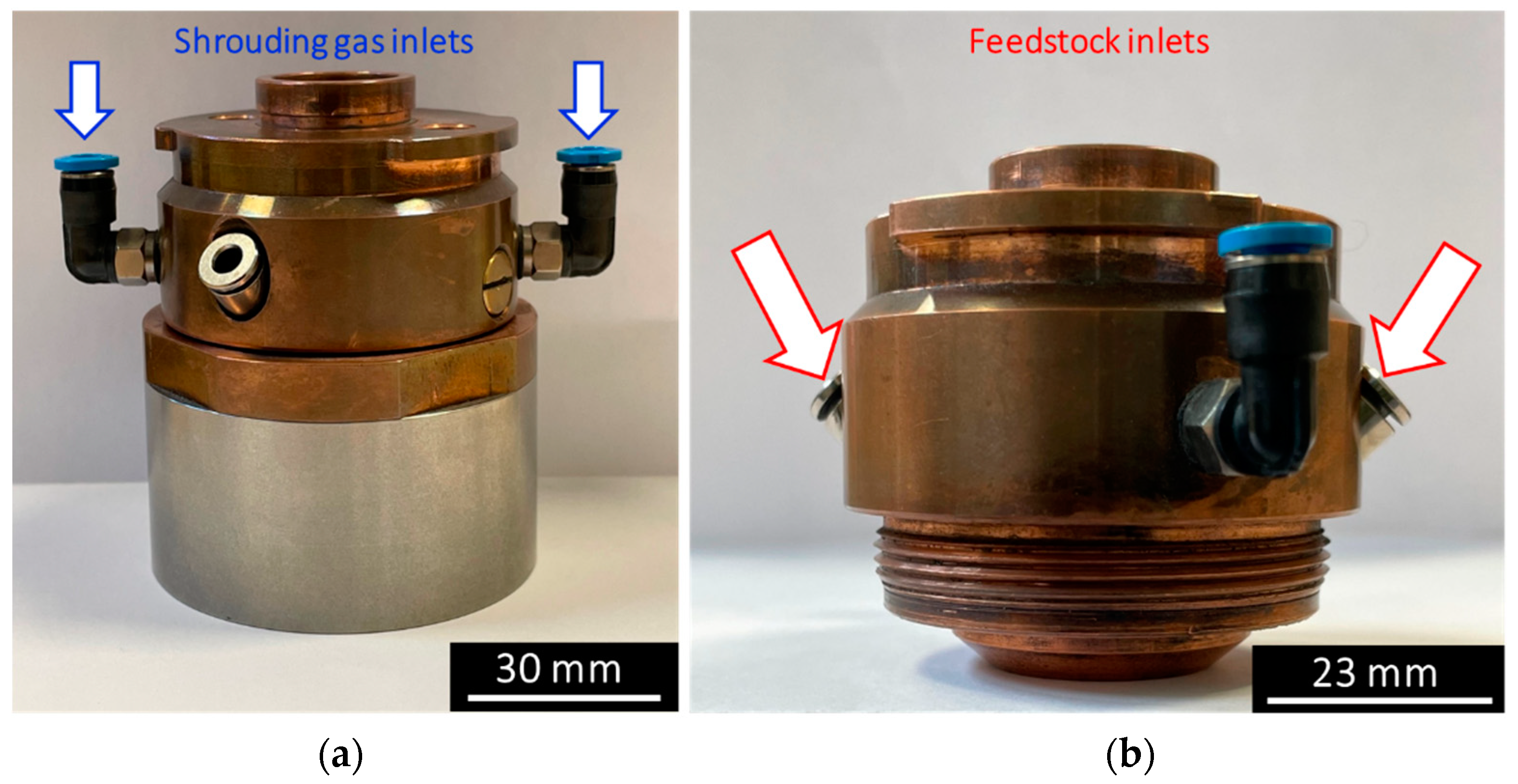
The used plasma coating nozzle with the additional shrouding gas attachment was developed and industrialized by INO GmbH (Figure 2). The shrouding gas stream (i.e., N2) was transferred by two external inlets around the plasma nozzle, by spreading the gas stream homogenously around the plasma jet downwards to the substrate. The shroud stream was set to 20 L·min−1 in order to minimize dust formation of the feedstock material. The solid powder feedstock was directly injected inside the plasma jet zone by two internal hose connections. A constant plasma jet in the range of 100 A was set by a DC generator at the beginning of each experiment. For generating the plasma jet as well as for all the coating experiments, a 10 L·min−1 non-tunable argon 5.0 (99.99%) gas flow setup was used. Before coating, the substrates were fixed on a movable steel sample holder platform with double-sided tape. Therefore, all the coating procedures were performed within a meandering shape. The complete coating parameter setup is shown in Table 1.

2.4. Tribological Tests

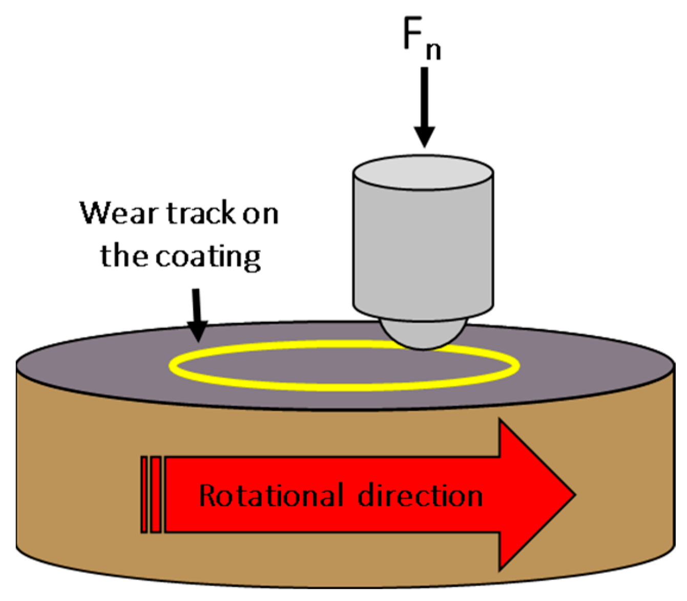
The TRB3 tribometer (Anton Paar®) in rotational mode was used for all the tribological tests in order to obtain the coefficient of friction (COF) as illustrated in Figure 3. Then, 100Cr6 counterpart steel balls (grade HRC 60/62) with a 6 mm diameter were utilized for all the experiments. Before the experiments, the steel balls were cleaned with ethanol (≥96%) and wiped with a tissue. The non-coated and coated samples were tribological investigated under ambient conditions (i.e., 20–23 °C). Each coating sample was measured three times with respect to reproducibility. The applied tribometer measurement parameters are summarized in Table 2. Aging tests were performed on elected coating samples (i.e., 100 A) to evaluate the wearability. The specific wear rate ( k i ) of the coating was calculated as the ratio between the wear volume in mm3 ( V i ) and the constant sliding force ( F ) times the total sliding distance ( s ) in meters as reported in [29] according to Equation (1).
k i = V i / ( F s )

2.5. Indentation Tests

Microindentation (MI) creep experiments were conducted by using an Anton Paar Micro Combi tester (MCT, Anton Paar, Graz, Austria) with a spherical diamond indenter (α = 120°) under ambient room conditions of 21 °C temperature and 35% relative humidity. The loading on the WS2-Zn as-deposited coatings on Si wafers was conducted linearly with a max. load of 50 mN. The holding time at constant force was 60 s when the creep of the coating was recorded. A total of 5 measurements on each coating sample were performed.

3. Results and Discussion

3.1. Feedstock, Roughness and Coating Thickness Analysis

Both the particle size distribution and the elemental composition of the initial composite feedstock (i.e., 75 wt% of WS2 and 25 wt% of Zn) are illustrated in Figure 4a (i.e., d50 = 7.5 µm) and Figure 4b, respectively. It was revealed that the roughness of the final coatings increased by a factor of 10 in contrast to the uncoated PEEK substrate (i.e., Ra ≤ 0.5 µm). It was observed that the plasma current and the powder gas flow have a clear impact on the final coating roughness. By increasing the plasma current (i.e., 100 A to 125 A), the coating roughness is reduced by 16%. In addition, the application of 150 A (e.g., 125 A to 150 A) at the same coating distance between plasma nozzle exit and substrate led to harsher plasma jet conditions and consequently to increased coating roughness >20%. Furthermore, the resulting coating thickness of the WS2-Zn system increases with higher plasma current independently of the powder gas flow setting of 10 L·min−1 as shown in Table 3. The smallest coating thickness increase (i.e., <13%) was measured with 15 L·min−1 powder gas flow in relation to the plasma current increase. The presented coating thickness of the WS2-Zn dry lubricant system (i.e., E3) was significantly increased by a factor of two in contrast to the MoS2-C-Zn dry lubricant system reported in [17].

3.2. Tribological Analysis

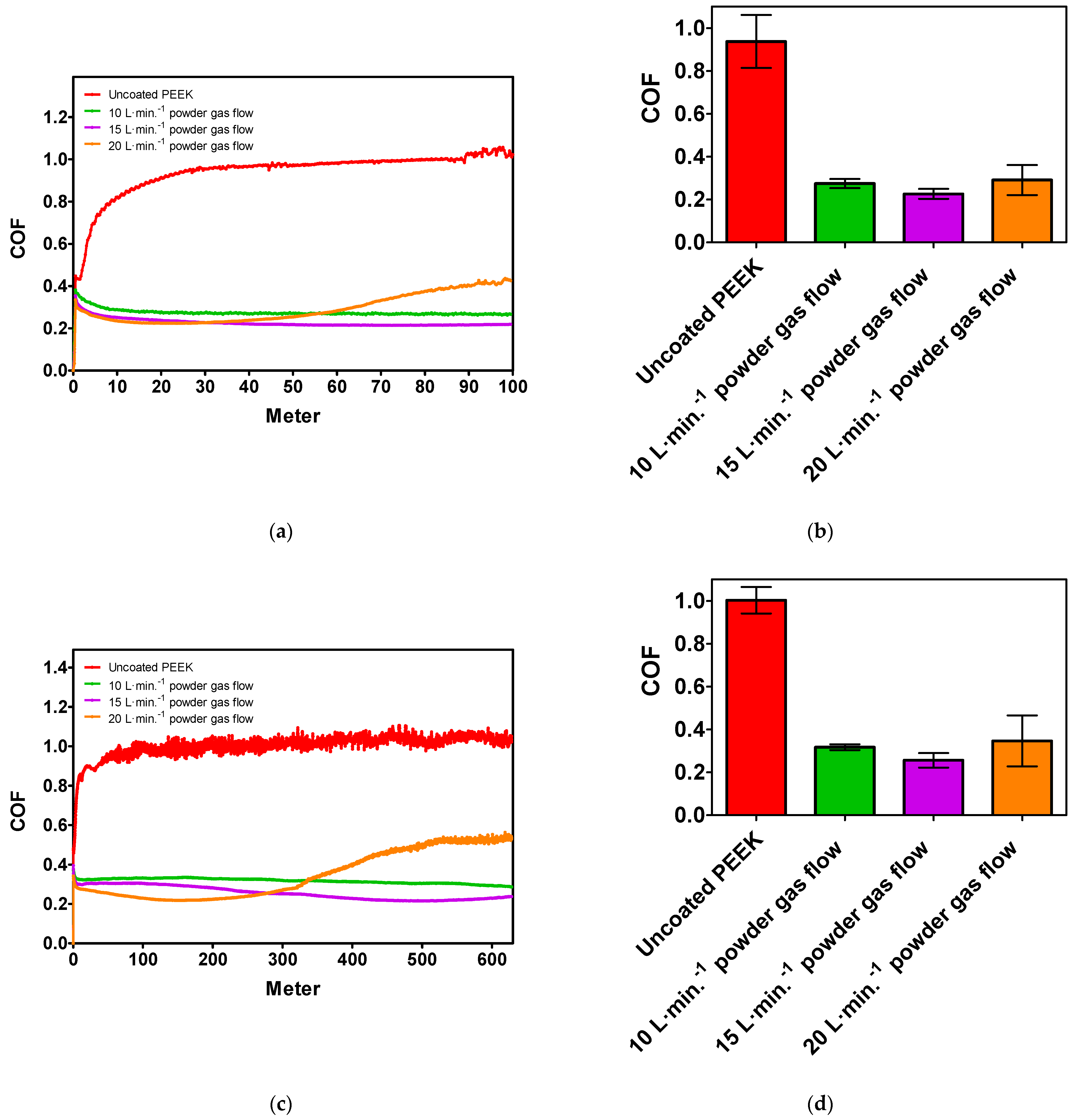
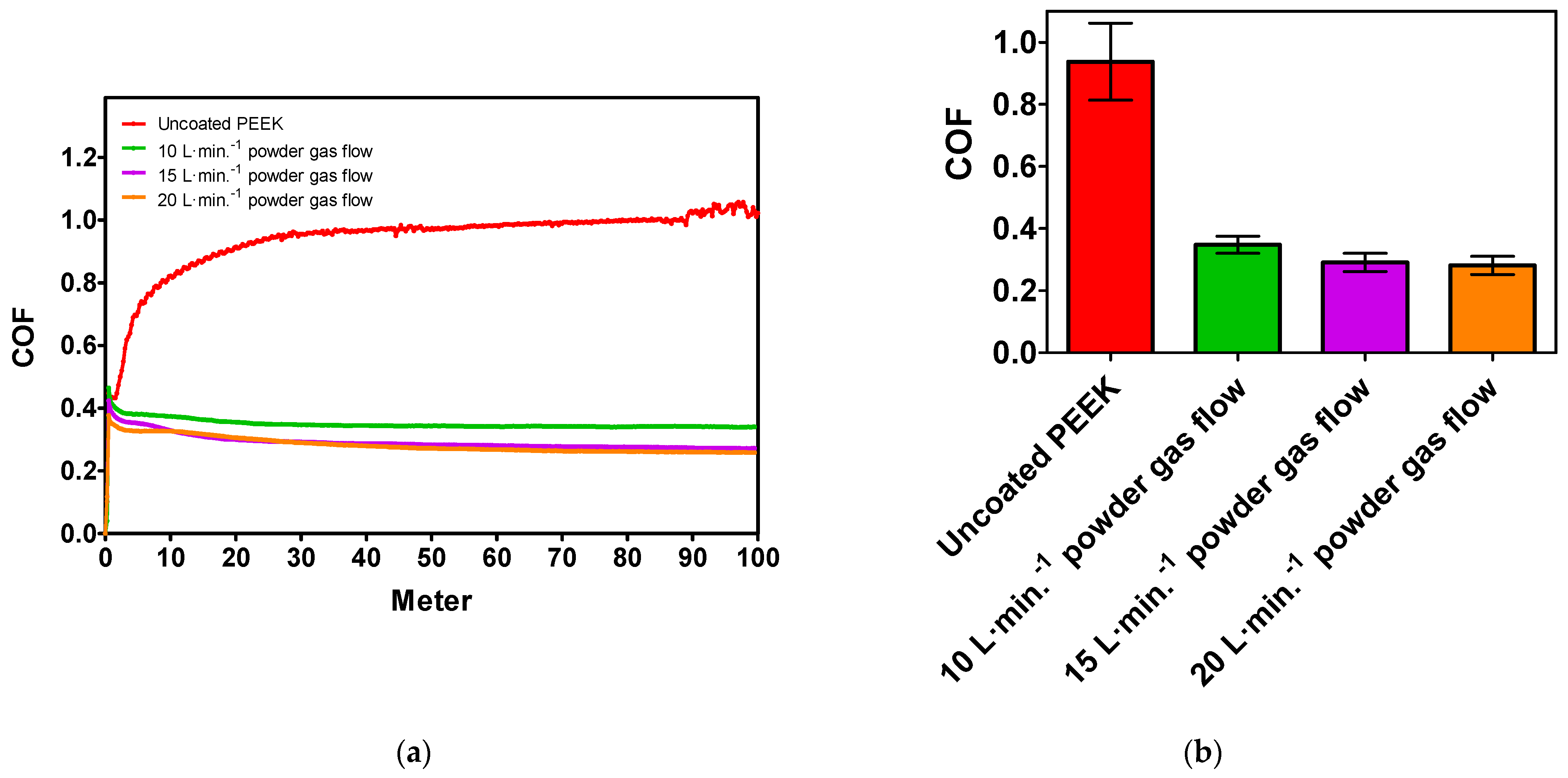
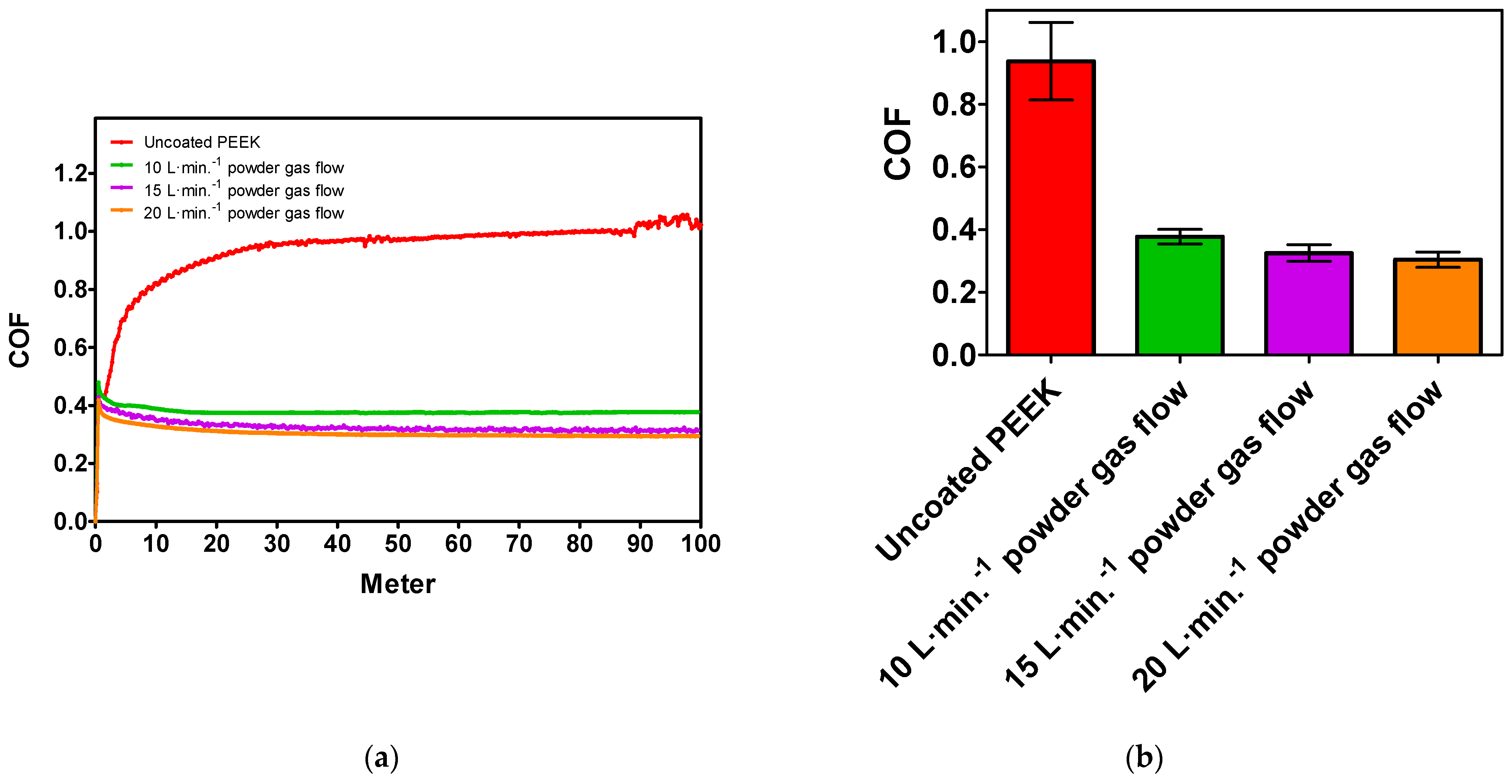
The obtained coefficient of friction (COF) results of the prepared WS2-Zn coatings on PEEK by the shrouding gas-assisted plasma deposition technique in relation to the plasma current (i.e., 100 A) and the powder gas stream are given in Figure 5a. The tribological progress of the WS2-Zn coating prepared with a 15 L·min−1 powder gas flow rate represents the most promising low-friction coating with a stable progress reaching a COF < 0.2. This is slightly lower than the value for the coating prepared with a 10 L·min−1 powder gas flow rate (i.e., averaged COF progress > 0.2) as shown in Figure 5b. By increasing the powder gas flow rate (i.e., 20 L·min−1), the COF progress starts to rise rapidly after a testing length of 35 m (i.e., >0.4 at the end of the measurement) was reached. The powder particles in sample E7 underwent the shortest particle dwell time in the plasma; consequently, the heat impact of the plasma was too low to embed the WS2 fraction inside the Zn matrix, which exhibits inherently low cohesion properties. Aging tests exhibited a similar trend with respect to the COF performance as shown in Figure 5c. By performing these tribological tests, the resulting angular velocity was reduced by half as depicted in Table 2. It was noticed that the COF of the coating with 20 L·min−1 powder gas flow rate performed excellently within the first 150 m, in contrast to lower powder gas flow rates. However, the low-friction properties vanished rapidly between the 300 m and 628 m. The coating with a 15 L·min−1 powder gas flow rate represented the most stable low-friction trend within the first 500 m. Then, the COF slightly started to increase from 0.21 to 0.23. In contrast, the coating with a 10 L·min−1 powder gas flow rate showed a long-term decrease in terms of the COF from 0.37 to 0.28 with a lasting downward trend. The averaged COF progress of the aging tests is illustrated in Figure 5d. By increasing the plasma current (i.e., 125 A), higher powder gas flow rates (i.e., 15 L·min−1 and 20 L·min−1) show better tribological progresses in contrast to 10 L·min−1 as illustrated in Figure 6a. Because of the long particle dwell time in the plasma jet for samples with 10 L·min−1, the probability for the oxidation of WS2 is much higher in contrast to shorter particle dwell times in the plasma jet for 15 L·min−1 and 20 L·min−1. In addition, the averaged COF results are illustrated in Figure 6b with a COF < 0.29 (i.e., 20 L·min−1), a COF <0.30 (i.e., 15 L·min−1) and a COF > 0.34 (i.e., 10 L·min−1). Similar progress is observable by tuning the plasma jet to 150 A as represented in Figure 7a. Nevertheless, the averaged COF results are shown in Figure 7b with a COF >0.30 (i.e., 20 L·min−1), a COF > 0.32 (i.e., 15 L·min−1) and a COF > 0.37 (i.e., 10 L·min−1). In general, increasing the plasma jet current from 100 A to 150 A causes higher COF progress over the tribological length when applying 10 L·min−1 and 15 L·min−1 powder gas flow rate. In contrast, when applying 100 A in combination with 20 L·min−1, the COF increases rapidly only after reaching 30 m of tribological length, which is not observed when using 125 A and 150 A.
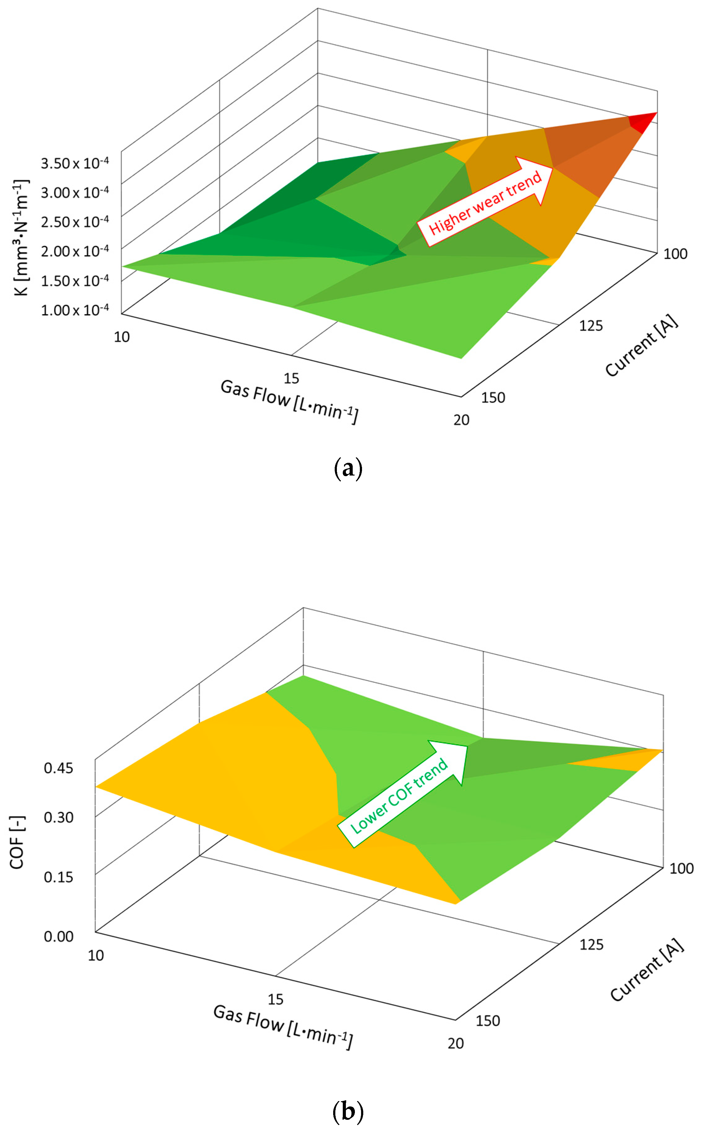
As reported in [30], the tribological performance (i.e., COF) of WS2 plasma coating rapidly reached >0.8. When comparing the WS2 plasma spray coating from [30] and the presented WS2-Zn plasma spray coating, a significant tribological improvement in COF by a factor of four was proven. In fact, the calculated wear rate (K) for coating E7 (i.e., 8.52 × 10⁻⁴ mm3 N−1m−1) represents a decreased trend towards 3.24 × 10⁻⁴ mm3 N−1m−1 in comparison to coating E1. The relationship between the plasma process settings and the resulting coating properties is shown in Figure 8.

3.3. SEM/EDS Analysis

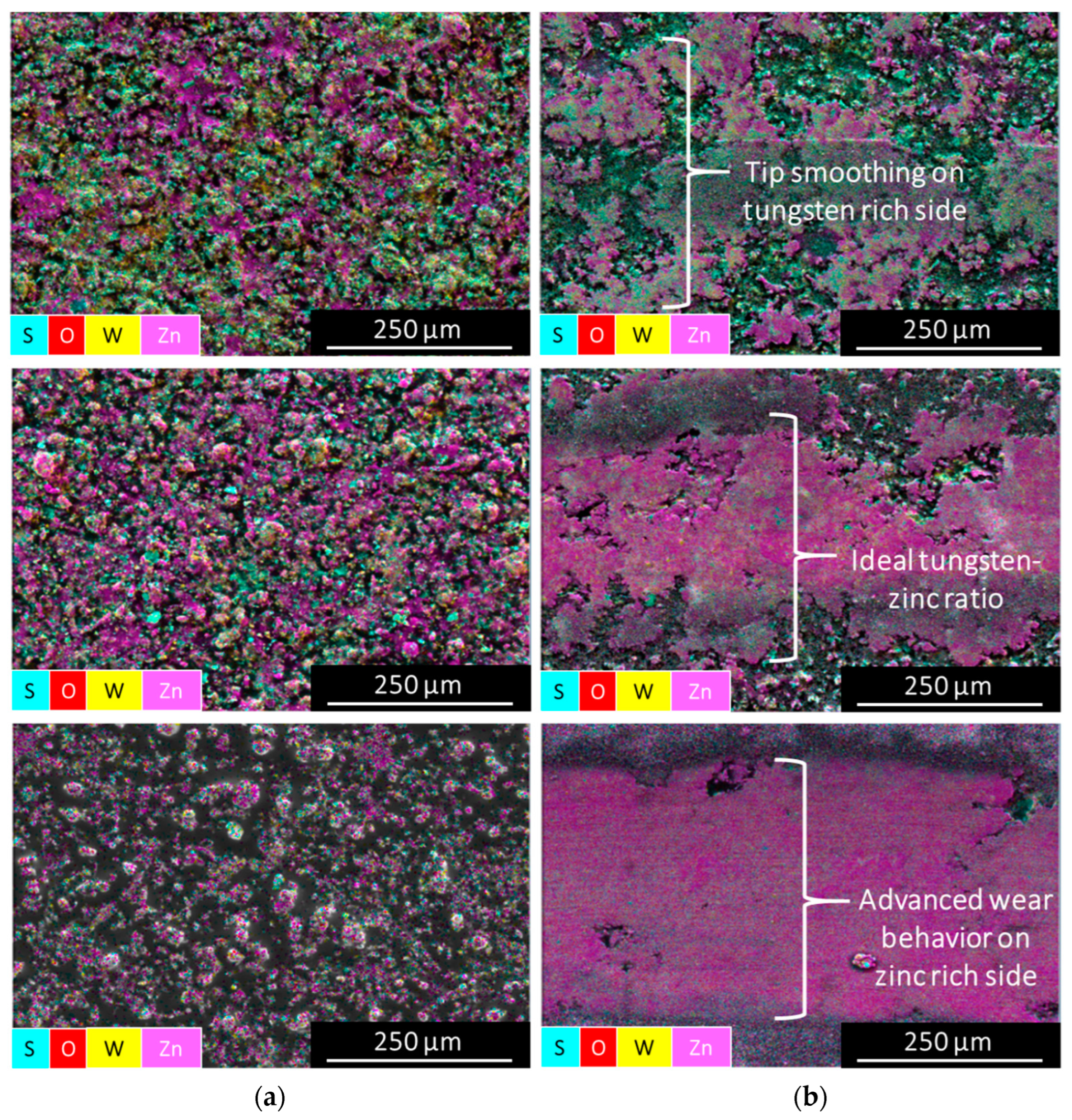
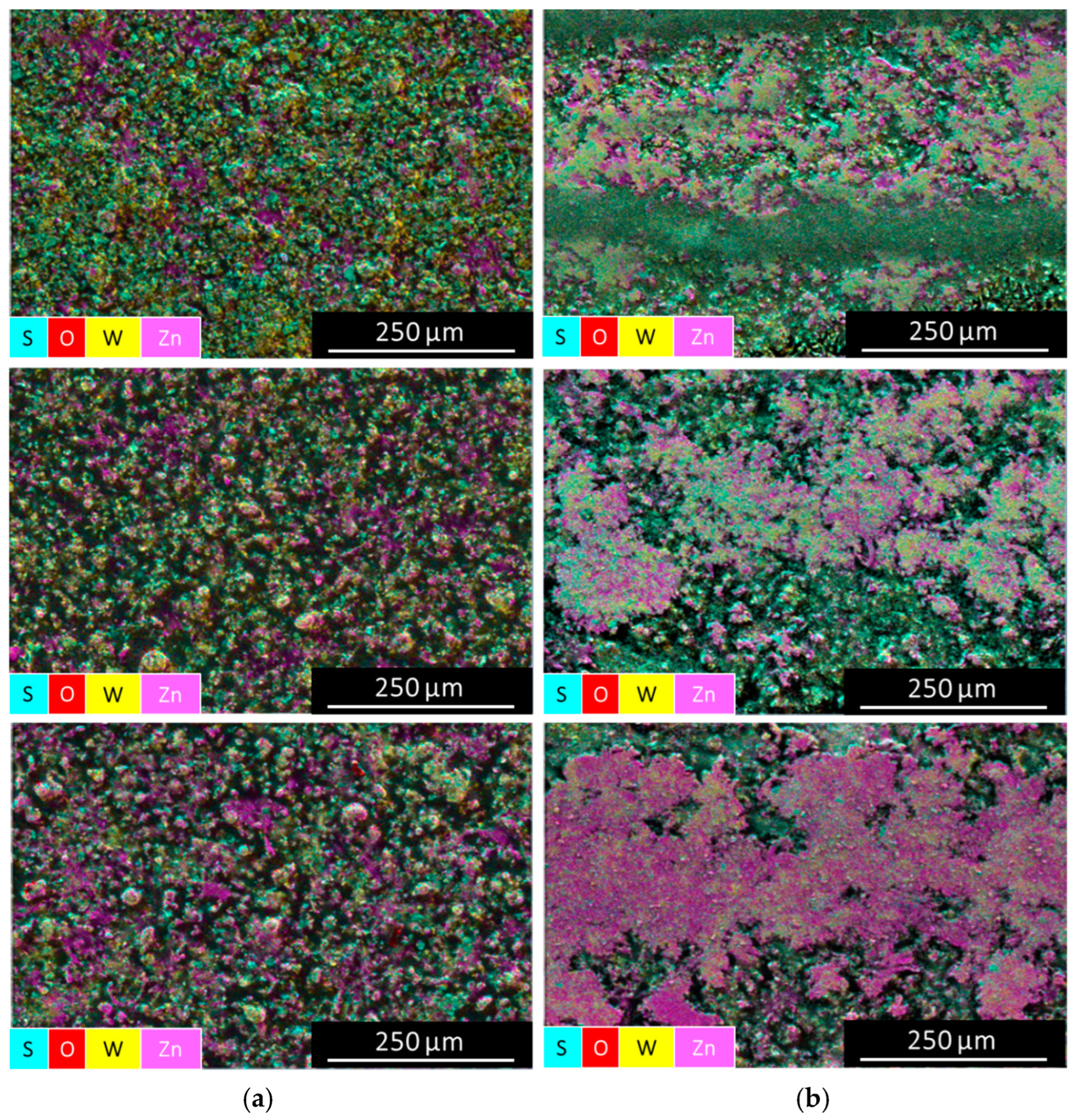
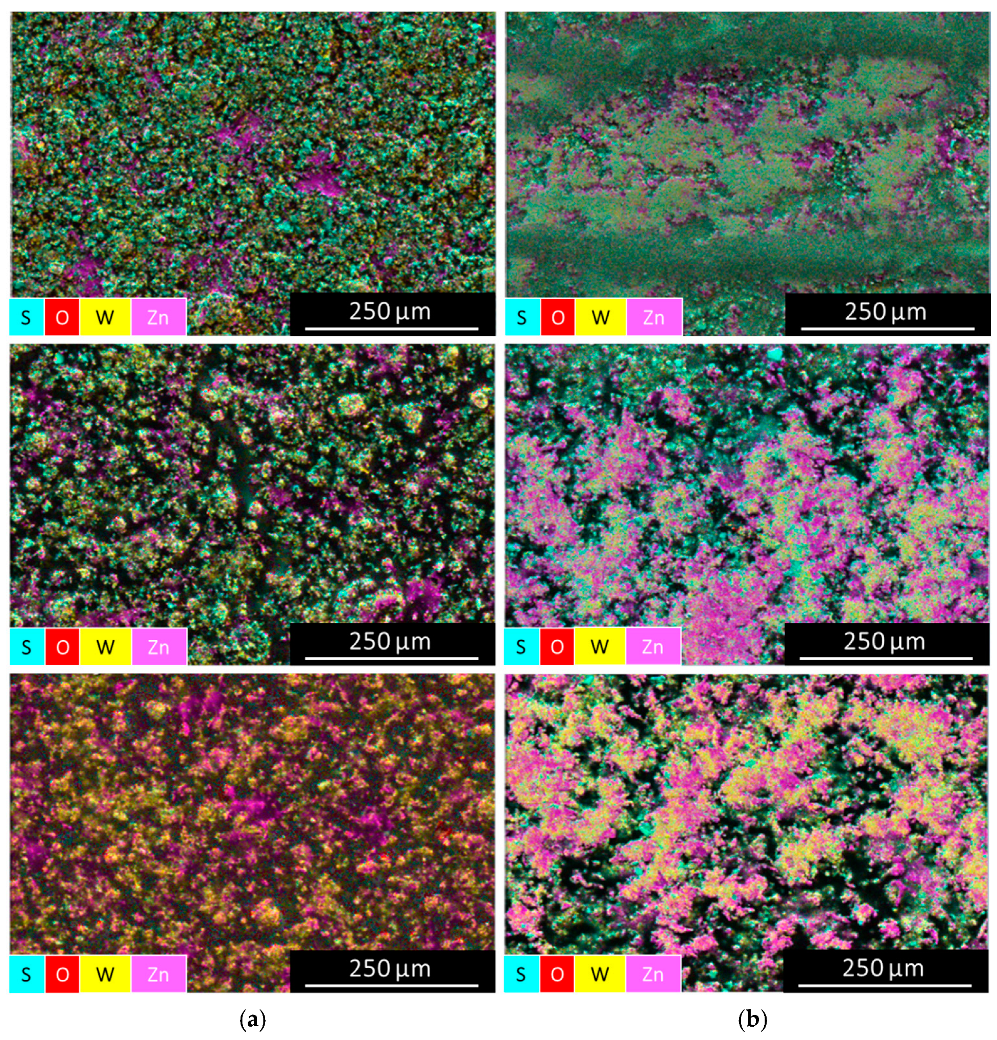
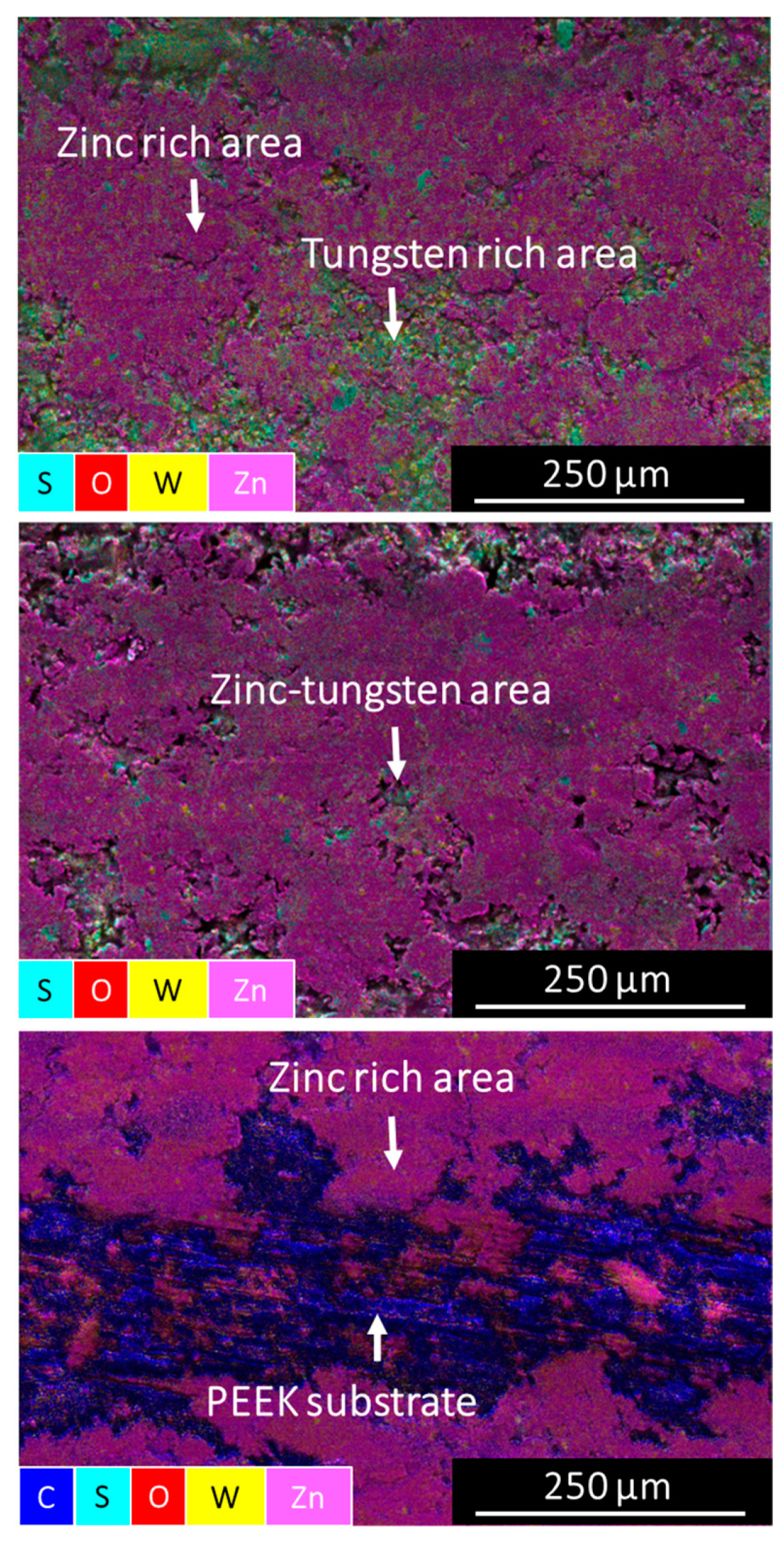
SEM/EDS investigations into as-deposited coatings and inside the wear track after tribological experiments were conducted to study the elemental composition of the coatings as a function of the plasma conditions/parameters (i.e., plasma current vs. powder gas flow rate). In Figure 9a, the powder gas flow rate variation (i.e., 10 L·min−1 to 20 L·min−1) of the as-deposited coatings prepared with a current of 100 A are compared. In fact, by increasing the powder gas flow rate the embedding mechanism of the WS2 fraction inside the Zn matrix was decreased (e.g., 12 wt% less tungsten content by 100 A/20 L·min−1setting in contrast to the 100 A/10 L·min−1 setting) as shown in Table 4. However, the Zn content in the as-deposited coating setting (i.e., 100 A/20 L·min−1) was increased by 19 wt% in comparison to the as-deposited coating (i.e., 100 A/10 L·min−1). This can be explained by the low melting temperature of Zn, i.e., 692.7 K [31], and the shorter dwell time in the plasma jet. By investigating the wear tracks in Figure 9b, a clear hardness-ductility variation was observed. Therefore, the coating becomes more ductile when the powder gas flow rate is >10 L·min−1. The EDS area analysis inside the wear track revealed a 42% increase in Zn content in comparison to the as-deposited coating within the 100 A/20 L·min−1 setting. In addition, the WS2 content was significantly reduced inside the wear track by >60% in contrast to the as-deposited coating. This resulted in a spontaneous COF increase from <0.3 to >0.4 over a distance of 70 m. Furthermore, a comparison of the wear rate of the counterpart ball (i.e., Fe) on the different WS2-Zn coatings (see Table 4) clearly verified that the powder gas flow rate is a decisive parameter within the plasma spray process for controlling the hardness properties of this particular coating system. The coating system in which the WS2-Zn feedstock was sprayed on the substrate with 10 L·min−1 exhibits harder coating properties in contrast to the coatings prepared by tuning the powder gas flow rate to >10 L·min−1. Moreover, in Figure 10, the three coatings as deposited prepared using a current of 125 A were examined as a function of the powder gas flow rate variation (i.e., 10 L·min−1 to 20 L·min−1). By increasing the powder gas flow rate within the 125 A series, the embedding mechanism of the WS2 fraction inside the Zn matrix was reduced (e.g., 11 wt% less tungsten content within the 125 A/20 L·min−1 setting in comparison to the 125 A/10 L·min−1 setting) as shown in Table 5. In addition, the Zn content in the as-deposited coating setting (i.e., 125 A/20 L·min−1) was increased by 36 wt% compared to the as-deposited coating (i.e., 125 A/10 L·min−1). The wear track analysis in Figure 10b shows a clear hardness–ductility trend of the coating. In fact, the coating becomes harder when the powder gas flow rate is <20 L·min−1, which correlates well with the higher tungsten content in the composite coating. The EDS area analysis (i.e., as deposited) revealed an 11% increase in tungsten content by setting the powder gas flow from 20 L·min−1 to 10 L·min−1. The WS2 content in coating E2 was less reduced inside the wear track by >5% in comparison to the as-deposited coating. However, the tip smoothening of coating E2 showed stable tribological progress, although the COF was continuously >0.3 while for coatings E5 (i.e., 125 A/15 L·min−1) and E8 (i.e., 125 A/20 L·min−1) a COF < 0.3 and more progressive valley smoothening were observed. As shown in Table 5, the wear rate of the counterpart ball (i.e., Fe) inside the wear track of coating E2 was significantly higher than in coating E5 and E8. Therefore, the coating system in which the WS2-Zn feedstock was sprayed on the substrate with 10 L·min−1 confirms higher hardness compared to the coatings E5 and E8 in which the powder gas flow rate was increased >10 L·min−1. In Figure 11, the as-deposited coatings prepared with 150 A were compared as a function of the powder gas flow rate variation (i.e., 10 L·min−1 to 20 L·min−1). By increasing the powder gas flow rate within the 150 A series, the embedding mechanism of the WS2 fraction inside the Zn matrix was slightly decreased (e.g., <4 wt% less tungsten content within the 150 A/20 L·min−1 setting in contrast to the 150 A/10 L·min−1 setting) as shown in Table 6. The Zn content in the as-deposited coating setting (i.e., 150 A/20 L·min−1) was increased by >20 wt% in contrast to the as-deposited coating (i.e., 150 A/10 L·min−1). In particular, the wear tracks of coatings E6 and E9 in Figure 11b show a similar hardness–ductility trend. Indeed, EDS area analysis confirmed the highest tungsten content in the composite coating E3 as depicted in Table 6, which correlates with the higher COF (>0.4) compared to the coatings E6 and E9 (<0.4). In addition, the wear rate of the counterpart ball inside the wear track of coating E3 correlates well with the Fe debris found in SEM/EDS (i.e., 1.3 wt%) in comparison to the coating E6 (i.e., 0.5 wt%) and coating E9 (i.e., 0.4 wt%). Furthermore, SEM/EDS investigations into the wear track of the WS2-Zn coatings (i.e., 100 A) with respect to wearability were conducted after a tribological performance length of 628 m (see Figure 12). The functionality of coating E1 and E4 is still granted. However, coating E4 exhibited a significant decrease in W and a significant increase in Zn in contrast to coating E1 according to Table 7. The outlook for increasing the tribological length of coating E4 seems to be negative in terms of coating stability. Coating E1 points out a longer lifespan in contrast to E4. Within coating E7, the substrate was significantly exposed, which revealed the tendency of high wear behavior.

3.4. XPS Analysis

In addition to SEM/EDS, XPS analysis was performed to obtain information about the elemental composition of the resulting WS2-Zn composite coatings and the chemical state of the relevant elements as a function of the plasma deposition variations (i.e., plasma current and powder gas flow rate). Therefore, in Figure 13a, the survey spectrum of the representative WS2-Zn coatings (i.e., initial feedstock as reference, coating E1, coating E4 and coating E7) is given. A comparison of the relevant single elements (i.e., tungsten, zinc and sulfur measured in at.%) of the feedstock before deposition and as deposited is presented in Table 8. In all the coatings, the sulfur concentration was significantly decreased (i.e., >80 at.%) in contrast to the initial reference feedstock. Furthermore, the amount of tungsten was also significantly reduced in all the coatings (i.e., >60 at.% in coating E7, >58 at.% in coating E4 and >48 at.% in coating E1). In Figure 13b, the observed W4f7/2 and W4f5/2 peaks at 31.6 and 33.7 eV can be attributed to the +4-oxidation state of tungsten in WS2 [32]. As illustrated in Figure 13c, the observed doublet in the high-resolution spectrum of Zn can be assigned to Zn2p3/2 (i.e., 1023.4 eV) and Zn2p1/2 (i.e., 1046.5 eV), indicating the formation of Zn(OH)2 [33]. In Figure 13d (high-resolution spectrum of S), the corresponding S2p3/2 and S2p1/2 peaks at the binding energy values of 162.3 and 163.5 eV were attributed to S2– as present in WS2 [34].

3.5. Creep Analysis

The creep results of the WS2-Zn coating system of E1, E4 and E7 according to the shear modulus (G), elastic modulus (E) and bulk modulus (K) are depicted in Table 9. The penetration depth was in the range of 3–5 µm according to a coating thickness of 14–17 µm. In fact, the suggested penetration depth is around 10% of the coating thickness (i.e., 1.4 µm). The highest creep moduli were determined on coating sample E4.

4. Conclusions

PEEK surfaces with high COF (>0.8) can be coated with a WS2-Zn composite based powder with a four-times-smaller COF by an atmospheric pressure plasma jet equipped with a shroud attachment.
The effect of tuning the plasma process parameters (i.e., plasma current and the powder gas flow rate) has been investigated and the following conclusions can be drawn:
  • The dry lubricant WS2 was well embedded into a Zn matrix giving low-friction coatings with an averaged coating thickness >14 µm, where no delamination (i.e., as deposited) was observed.
  • By increasing the plasma current from 100 to 150 A, the coating thickness increases independently of the powder gas flow rate (i.e., increase of >35% with 10 L·min−1, >10% with 15 L·min−1 and >35% with 20 L·min−1 powder gas flow).
  • By increasing the plasma current (i.e., from 100 to 150 A), the tungsten content increases independently of the powder gas flow rate with respect to the as-deposited coatings by SEM/EDS area analysis (i.e., increase of >19 wt% with 10 L·min−1, >20 wt% with 15 L·min−1 and >26 wt% with 20 L·min−1 powder gas flow).
  • By increasing the plasma current (i.e., from 100 to 150 A), the zinc content decreases independently of the powder gas flow rate according to the as-deposited coatings by SEM/EDS area analysis (i.e., factor of 2 with 10 L·min−1, factor of 1.8 with 15 L·min−1 and factor of 1.9 with 20 L·min−1 powder gas flow).
  • “Harder” coatings are generated by tuning the powder gas flow rate to lower levels (i.e., a 10 L·min−1 powder gas flow is more beneficial than 20 L·min−1 powder gas flow) in terms of aging. In addition, the Zn content variation inside the wear track represents a clear trend in terms of ductility properties, which is independent on the applied plasma current setting.
  • According to the high-resolution sulfur (at.%) spectra (XPS), the quantitative loss of sulfur was significantly high as a result of the plasma coating process dependent on the plasma setup (i.e., parameters such as plasma current or powder flow rate) in contrast to the initial WS2-Zn feedstock, which was mainly affected by the plasma current and the powder gas flow rate. In fact, a loss between 81 and 89 at.% was determined (i.e., 100 A plasma jet setting).
In this study, different WS2-Zn coatings were generated by a shroud-assisted plasma jet providing either harder or more ductile properties as desired by industry for versatile engineering applications. In fact, automotive high-performance parts with a comparatively high COF (e.g., unfilled PEEK with a COF > 0.8) can be easily coated by atmospheric pressure plasma deposition for significantly lowering possible friction and wear between parts in permanent motion, thus promoting sustainable development.

Author Contributions

Conceptualization, D.K.; Methodology, D.K., C.B. and T.P.; Investigation, D.K.; Data curation, D.K. and C.B.; Writing—original draft, D.K.; Writing—review & editing, D.K. and R.K.; Visualization, D.K.; Supervision, R.K. and A.M.C.; Project administration, W.W.; Funding acquisition, W.W. All authors have read and agreed to the published version of the manuscript.

Funding

All the investigation activities were fully funded by the project FunctionalWOOD2print [grant number 898680, 2023] and ThermoMelt4PA [grant number 877377, 2020] within the framework of the Austrian Research Promotion Agency (FFG) scheme.

Institutional Review Board Statement

Not applicable.

Informed Consent Statement

Not applicable.

Data Availability Statement

Data are contained within the article.

Acknowledgments

This research article was performed at the Joanneum Research Forschungsgesellschaft m.b.H MATERIALS in Niklasdorf, Austria. INO GmbH, Austria, is gratefully acknowledged for providing the complete coating system.

Conflicts of Interest

Authors Dietmar Kopp, Reinhard Kaindl, Thomas Prethaler and Wolfgang Waldhauser were employed by the company Joanneum Research Forschungsgesellschaft m.b.H. The remaining authors declare that the research was conducted in the absence of any commercial or financial relationships that could be construed as a potential conflict of interest.

References

  1. Wu, T.; Zhang, X.; Chen, K.; Chen, Q.; Yu, Z.; Feng, C.; Zhang, D. The antibacterial and wear-resistant nano-ZnO/PEEK composites were constructed by a simple two-step method. J. Mech. Behav. Biomed. Mater. 2022, 126, 104986. [Google Scholar] [CrossRef] [PubMed]
  2. Wang, B.; Zhang, K.; Zhou, C.; Ren, M.; Gu, Y.; Li, T. Engineering the mechanical properties of CNT/PEEK nanocomposites. RSC Adv. 2019, 9, 12836–12845. [Google Scholar] [CrossRef] [PubMed]
  3. Niu, X.; Song, J.L.G.; Li, Y.; He, T. Evidence of high temperature stable performance of polyether ether ketone (PEEK) separator with sponge-structured in lithium-ion battery. J. Mater. Sci. 2022, 57, 7042–7055. [Google Scholar] [CrossRef]
  4. Zorko, D.; Kulovec, S.; Duhovnik, J.; Tavcar, J. Durability and design parameters of a Steel/PEEK gear pair. Mech. Mach. Theory 2019, 140, 825–846. [Google Scholar] [CrossRef]
  5. Molazemhosseini, A.; Tourani, H.; Khavandi, A.; Yekta, B.E. Tribological performance of PEEK based hybrid composites reinforced with short carbon fibers and nano-silica. Wear 2013, 303, 397–404. [Google Scholar] [CrossRef]
  6. Song, J.; Liao, Z.; Shi, H.; Xiang, D.; Liu, Y.; Liu, W.; Peng, Z. Fretting Wear Study of PEEK-Based Composites for Bio-implant Application. Tribol. Lett. 2017, 65, 150. [Google Scholar] [CrossRef]
  7. Fiołek, A.; Zimowski, S.; Kopia, A.; Sitarz, M.; Moskalewicz, T. Effect of Low-Friction Composite Polymer Coatings Fabricated by Electrophoretic Deposition and Heat Treatment on the Ti-6Al-4V Titanium Alloy’s Tribological Properties. Metall. Mater. Trans. A 2020, 51, 4786–4798. [Google Scholar] [CrossRef]
  8. Fiołek, A.; Zimowski, S.; Kopia, A.; Łukaszczyk, A.; Moskalewicz, T. Electrophoretic Co-deposition of Polyetheretherketone and Graphite Particles: Microstructure, Electrochemical Corrosion Resistance, and Coating Adhesion to a Titanium Alloy. Materials 2020, 13, 3251. [Google Scholar] [CrossRef]
  9. Yan, Y.; Jiang, C.; Huo, Y.; Li, C. Preparation and Tribological Behaviors of Lubrication-Enhanced PEEK Composites. Appl. Sci. 2020, 10, 7536. [Google Scholar] [CrossRef]
  10. Vazirisereshk, M.R.; Martini, A.; Strubbe, D.A.; Baykara, M.Z. Solid lubrication with MoS2: A review. Lubricants 2019, 7, 57. [Google Scholar] [CrossRef]
  11. Spychalski, W.L.; Pisarek, M.; Szoszkiewicz, R. Microscale insight into oxidation of single MoS2 crystals in air. J. Phys. Chem. C 2017, 121, 26027–26033. [Google Scholar] [CrossRef]
  12. Singer, I.L.; Fayeulle, S.; Ehni, P.D. Wear behavior of triode-sputtered MoS2 coatings in dry sliding contact with steel and ceramics. Wear 1996, 195, 7–20. [Google Scholar] [CrossRef]
  13. Mikhailov, S.; Savan, A.; Pflüger, E.; Knoblauch, L.; Hauert, R.; Simmonds, M.; Van Swygenhoven, H. Morphology and tribological properties of metal (oxide)–MoS2 nanostructured multilayer coatings. Surf. Coat. Technol. 1998, 105, 175–183. [Google Scholar] [CrossRef]
  14. Simmonds, M.C.; Savan, A.; Pflüger, E.; Van Swygenhoven, H. Mechanical and tribological performance of MoS2 co-sputtered composites. Surf. Coat. Technol. 2000, 126, 15–24. [Google Scholar] [CrossRef]
  15. Efeoglu, I.; Baran, Ö.; Yetim, F.; Altıntaş, S. Tribological characteristics of MoS2–Nb solid lubricant film in different tribo-test conditions. Surf. Coat. Technol. 2008, 203, 766–770. [Google Scholar] [CrossRef]
  16. Wang, X.; Xing, Y.; Ma, S.; Zhang, X.; Xu, K.; Teer, D.G. Microstructure and mechanical properties of MoS2/titanium composite coatings with different titanium content. Surf. Coat. Technol. 2007, 201, 5290–5293. [Google Scholar] [CrossRef]
  17. Kopp, D.; Gleirscher, M.; Stummer, M.; Major, L.; Hausberger, A.; Schlögl, S.; Lackner, J.M.; Kaindl, R.; Prethaler, T.; Coclite, A.M.; et al. Ternary low-friction coatings on thermoplastics by plasma spraying: Investigations on the process-structure. Surf. Coat. Technol. 2024, 477, 130303. [Google Scholar] [CrossRef]
  18. Reinert, L.; Green, I.; Gimmler, S.; Lechthaler, B.; Mücklich, F.; Suárez, S. Tribological behavior of self-lubricating carbon nanoparticle reinforced metal matrix composites. Wear 2018, 408–409, 72–85. [Google Scholar] [CrossRef]
  19. Zhu, R.; Zhang, P.; Yu, Z.; Yan, H.; Li, S.; Wu, D.; Shi, H.; Tian, Y. Microstructure and wide temperature range self-lubricating properties of laser cladding NiCrAlY/Ag2O/Ta2O5 composite coating. Surf. Coat. Technol. 2020, 383, 125248. [Google Scholar] [CrossRef]
  20. Zhou, Z.Y.; Liu, X.B.; Zhuang, S.G.; Yang, X.H.; Wang, M.; Sun, C.F. Preparation and high temperature tribological properties of laser in-situ synthesized self-lubricating composite coatings containing metal sulfides on Ti6Al4V alloy. Appl. Surf. Sci. 2019, 481, 209–218. [Google Scholar] [CrossRef]
  21. Tharajak, J.; Palathai, T.; Sombatsompop, N. Recommendations for h-BN loading and service temperature to achieve low friction coefficient and wear rate for thermal-sprayed PEEK coatings. Surf. Coat. Technol. 2017, 321, 477–483. [Google Scholar] [CrossRef]
  22. Kopp, D.; Lackner, J.M.; Kaindl, R.; Elter, R.; Stummer, M.; Hinterer, A.; Coclite, A.M.; Waldhauser, W. Low-friction, wear-protecting coatings on polymers by atmospheric pressure plasma spraying. Surf. Coat. Technol. 2022, 448, 128930. [Google Scholar] [CrossRef]
  23. Herman, H.; Sampath, S.; McCune, R. Thermal Spray: Current Status and Future Trends. MRS Bull. 2000, 25, 17–25. [Google Scholar] [CrossRef]
  24. Gateman, S.M.; Alidokht, S.A.; Mena-Morcillo, E.; Schulz, R.; Chromik, R.R.; Kietzig, A.M.; Parkin, I.P.; Mauzeroll, J. Wear resistant solid lubricating coatings via compression molding and thermal spraying technologies. Surf. Coat. Technol. 2021, 426, 127790. [Google Scholar] [CrossRef]
  25. Prasad, S.V.; McDevitt, N.T.; Zabinski, J.S. Tribology of tungsten disulfide–nanocrystalline zinc oxide adaptive lubricant films from ambient to 500 °C. Wear 2000, 237, 186–196. [Google Scholar] [CrossRef]
  26. Scharf, T.W.; Prasad, S.V.; Dugger, M.T.; Kotula, P.G.; Goeke, R.S.; Grubbs, R.K. Growth, structure, and tribological behavior of atomic layer-deposited tungsten disulphide solid lubricant coatings with applications to MEMS. Acta Mater. 2006, 54, 4731–4743. [Google Scholar] [CrossRef]
  27. Zhang, X.F.; Xiao, F.; Zhang, X.L.; Wang, A.H.; Huang, Z.W. Microstructure and properties of HVOF sprayed Ni-based submicron WS2/CaF2 self-lubricating composite coating. Trans. Nonferrous Met. Soc. China 2009, 19, 85–92. [Google Scholar] [CrossRef]
  28. Planche, M.P.; Liao, H.; Coddet, C. Oxidation control in atmospheric plasma spraying coating. Surf. Coat. Technol. 2007, 202, 69–76. [Google Scholar] [CrossRef]
  29. Liang, X.; Su, Y.; Yang, T.; Dai, Z.; Wang, Y.; Yong, X. Study on the wear resistance and mechanism of AlCrCuFe2NiTix high-entropy surfacing alloys. J. Alloys Compd. 2024, 971, 172510. [Google Scholar] [CrossRef]
  30. Grützmacher, P.G.; Schranz, M.; Hsu, C.J.; Bernardi, J.; Steiger-Thirsfeld, A.; Hensgen, L.; Ripoll, M.R.; Gachot, C. Solid lubricity of WS2 and Bi2S3 coatings deposited by plasma spraying and air spraying. Surf. Coat. Technol. 2022, 446, 128772. [Google Scholar] [CrossRef]
  31. Nordberg, G.F.; Fowler, B.A.; Nordberg, M. Handbook on the Toxicology of Metals, 4th ed.; Academic Press: San Diego, CA, USA, 2015. [Google Scholar]
  32. Deepthi, B.; Barshilia, H.C.; Rajam, K.S.; Konchady, M.S.; Pai, D.M.; Sankar, J.; Kvit, A.V. Structure, morphology and chemical composition of sputter deposited nanostructured Cr–WS2 solid lubricant coatings. Surf. Coat. Technol. 2010, 205, 565–574. [Google Scholar] [CrossRef]
  33. Jeong, G.H.; Jang, H.S.; Yoon, J.C.; Lee, Z.; Yang, J.; Jang, A.R.; Ryu, G.H. Morphologically Controlled Synthesis of Reduced-Dimensional ZnO/Zn(OH)2 Nanosheets. ACS Omega 2022, 7, 35834–35839. [Google Scholar] [CrossRef] [PubMed]
  34. Dupin, J.C.; Gonbeau, D.; Martin-Lias, I.; Vinatier, P.; Levasseur, A. Amorphous oxysulfide thin films MOySz (M=W, Mo, Ti) XPS characterization: Structural and electronic peculiarities. Appl. Surf. Sci. 2001, 173, 140–150. [Google Scholar] [CrossRef]
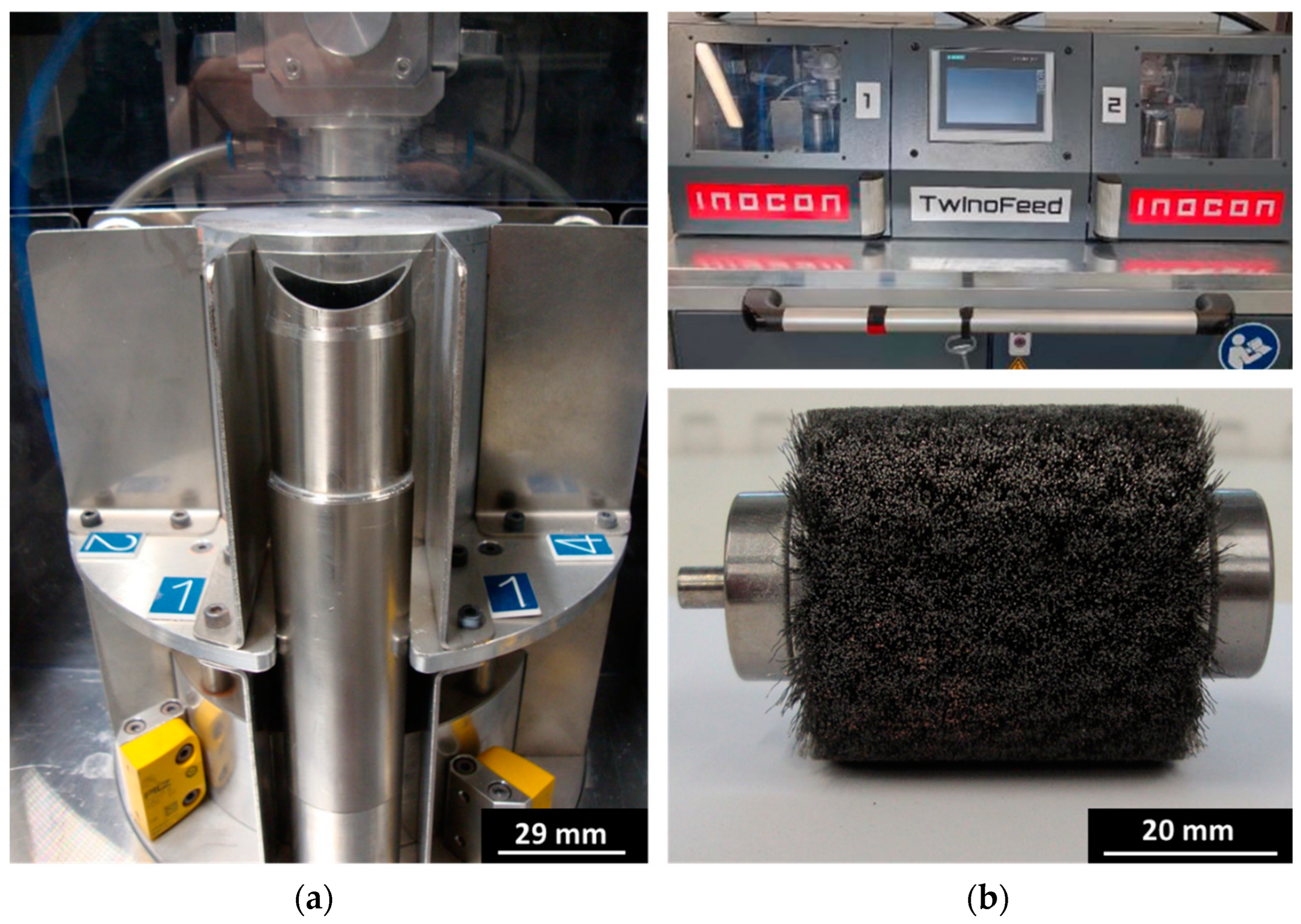
Figure 1. Powder brush feeder (TwinoFeed) for the WS2-Zn coating illustrating the feedstock vessel (a) with the front view of the human–machine interface (i.e., SIEMENS SIMATIC HMI) and the stainless brush (b).
Coatings 14 01365 g001
Figure 2. InoCoat 3 APPJ-nozzle from INO GmbH equipped with the shrouding gas part, which is attached to a screw thread (a). Feedstock inlets (b) that allow the transport of solid powders or powder mixtures directly to the plasma jet with the help of a powder carrier gas flow.
Coatings 14 01365 g002
Figure 3. Ball-on-disk tribometer TRB3 (Anton Paar) in rotating mode.
Coatings 14 01365 g003
Figure 4. Particle size distribution (a) and the SEM/EDS area analysis (b) of the WS2-Zn feedstock before coating.
Coatings 14 01365 g004
Figure 5. Tribological performance of the WS2-Zn coatings on PEEK generated with 100 A plasma current as a function of the powder gas flow variation over a testing length of 100 m (a) with the averaged COF results (b) and aging tests over a testing length of 628 m (c) with the averaged COF results (d).
Coatings 14 01365 g005
Figure 6. Tribological performance of the WS2-Zn coatings on PEEK generated with 125 A plasma current as a function of the powder gas flow variation over a testing length of 100 m (a) with the averaged COF results (b).
Coatings 14 01365 g006
Figure 7. Tribological performance of the WS2-Zn coatings on PEEK generated with 150 A plasma current as a function of the powder gas flow variation over a testing length of 100 m (a) with the averaged COF results (b).
Coatings 14 01365 g007
Figure 8. Relationship between the plasma process settings and the coating properties of the WS2-Zn coating. The powder gas flow rate and current impact in relation to wear (a) and low-friction (b) behavior.
Coatings 14 01365 g008
Figure 9. SEM/EDS area analysis of the resulting WS2-Zn coatings as deposited (a) and inside the wear track (b) generated at 100 A plasma current and by tuning the powder gas flow rate. Top: 10 L·min−1; middle: 15 L·min−1; bottom: 20 L·min−1.
Coatings 14 01365 g009
Figure 10. SEM/EDS area analysis of the resulting WS2-Zn coatings as deposited (a) and inside the wear track (b) generated at 125 A plasma current and by tuning the powder gas flow rate. Top: 10 L·min−1; middle: 15 L·min−1; bottom: 20 L·min−1.
Coatings 14 01365 g010
Figure 11. SEM/EDS area analysis of the resulting WS2-Zn coatings as deposited (a) and inside the wear track (b) generated at 150 A plasma current and by tuning the powder gas flow rate. Top: 10 L·min−1; middle: 15 L·min−1; bottom: 20 L·min−1.
Coatings 14 01365 g011
Figure 12. SEM/EDS area analysis of the resulting WS2-Zn coatings inside the wear track generated at 100 A plasma current and by tuning the powder gas flow rate. Top: 10 L·min−1; middle: 15 L·min−1; bottom: 20 L·min−1.
Coatings 14 01365 g012
Figure 13. XPS survey spectra (a) and high-resolution spectra of W4f (b), Zn2p (c) and S2p (d) of the WS2-Zn coatings.
Coatings 14 01365 g013
Table 1. Shrouding gas atmospheric pressure plasma deposition setting of all experiments.
APPJ SettingApplied Parameter
Plasma jet current [A]100; 125; 150
Powder gas flow [L·min−1] to the plasma10; 15; 20
Plasma nozzle exit-substrate distance [mm]30
Coating velocity [mm·s−1]200
Linear coating passes [#]5
Feedstock supply [g·min−1]2
Ar gas flow [L·min−1]10
N2 shrouding gas flow [L·min−1]20
Table 2. Parameters for tribological tests on the ball-on-disk tribometer in rotational mode (TRB3 Anton Paar).
Wear Track
Diameter
Linear VelocityStatic CounterpartTest LengthNormal
Load
Hertzian Stress
10 mm25 mm·s−1100Cr6 ball100 m1 N79 MPa
20 mm25 mm·s−1100Cr6 ball628 m1 N79 MPa
Table 3. Mean roughness (Ra) values evaluated by an optical profilometer (MicroProf® 300, FRT Metrology, Bergisch Gladbach, Germany) and the resulting coating thickness determined by three tactile measurements per sample (Dektak 150 surface profiler Veeco-Dektak 150, Veeco Corporate, Plainview, NY, USA).
Sample Type/Coating NumberRa (μm)Coating Thickness (µm)
Uncoated PEEK≤0.50-
100 A coating with 10 L·min−1 powder gas flow/E14.90 ± 0.9216.14 ± 0.41
125 A coating with 10 L·min−1 powder gas flow/E24.14 ± 0.7124.83 ± 0.12
150 A coating with 10 L·min−1 powder gas flow/E35.36 ± 0.8825.98 ± 0.16
100 A coating with 15 L·min−1 powder gas flow/E44.89 ± 0.9317.23 ± 0.15
125 A coating with 15 L·min−1 powder gas flow/E54.08 ± 0.6718.99 ± 0.05
150 A coating with 15 L·min−1 powder gas flow/E64.58 ± 0.9519.57 ± 0.04
100 A coating with 20 L·min−1 powder gas flow/E75.49 ± 1.1814.32 ± 0.23
125 A coating with 20 L·min−1 powder gas flow/E84.56 ± 1.0615.04 ± 0.11
150 A coating with 20 L·min−1 powder gas flow/E95.12 ± 0.8422.17 ± 0.37
Table 4. Resulting WS2-Zn SEM/EDS area analysis of the 100 A generated coatings in relation to the powder gas flow (i.e., E1…10 L·min−1; E4…15 L·min−1; E7…20 L·min−1).
SEM/EDS Analysis wt%
WZnSOFeTotal
WS2-Zn as deposited of E161.030.55.53.0-100
WS2-Zn wear track of E157.431.96.14.10.5100
WS2-Zn as deposited of E459.131.86.42.7-100
WS2-Zn wear track of E450.836.78.24.20.1100
WS2-Zn as deposited of E753.537.65.73.2-100
WS2-Zn wear track of E718.965.52.513.1<LOD100
Table 5. Resulting WS2-Zn SEM/EDS area analysis of the 125 A generated coatings in relation to the powder gas flow (i.e., E2…10 L·min−1; E5…15 L·min−1; E8…20 L·min−1).
SEM/EDS Analysis wt%
WZnSOFeTotal
WS2-Zn as deposited of E274.016.36.53.2-100
WS2-Zn wear track of E269.119.06.74.30.9100
WS2-Zn as deposited of E573.118.37.61.0-100
WS2-Zn wear track of E563.926.36.52.80.5100
WS2-Zn as deposited of E865.925.56.22.4-100
WS2-Zn wear track of E848.542.44.94.00.2100
Table 6. Resulting WS2-Zn SEM/EDS area analysis of the 150 A generated coatings in relation to the powder gas flow (i.e., E3…10 L·min−1; E6…15 L·min−1; E9…20 L·min−1).
SEM/EDS Analysis wt%
WZnSOFeTotal
WS2-Zn as deposited of E375.415.05.73.9-100
WS2-Zn wear track of E371.316.45.95.11.3100
WS2-Zn as deposited of E674.817.26.41.6-100
WS2-Zn wear track of E664.825.75.33.70.5100
WS2-Zn as deposited of E972.919.76.50.9-100
WS2-Zn wear track of E962.528.34.74.10.4100
Table 7. Aging results of the WS2-Zn SEM/EDS area analysis (i.e., wear track) of the 100 A generated coatings in relation to the powder gas flow (i.e., E1…10 L·min−1; E4…15 L·min−1; E7…20 L·min−1).
SEM/EDS Analysis wt%
CWZnSOFeTotal
WS2-Zn wear track of E1-43.146.43.66.60.3100
WS2-Zn wear track of E4-27.561.32.68.50.1100
WS2-Zn wear track of E760.43.927.60.47.7<LOD100
Table 8. Surface composition (at.%) of WS2-Zn feedstock and coating E1–E7 based on XPS survey spectra analysis.
FeedstockCoating E1Coating E4Coating E7
avg.SDavg.SDavg.SDavg.SD
S2p35.50.93.90.56.70.96.20.5
W4f14.90.97.70.56.20.65.70.0
O1s16.61.646.30.953.22.646.75.0
C1s30.21.729.91.617.65.226.52.7
Zn2p2.80.512.20.616.31.212.51.6
Table 9. G/E/K creep results of WS2-Zn coating E1, E4 and E7 as deposited.
SampleG [GPa]E [GPa]K [GPa]
WS2-Zn (E1)0.51 ± 0.241.32 ± 0.641.10 ± 0.53
Min–max.0.25–0.990.64–2.570.54–2.14
WS2-Zn (E4)0.96 ± 0.592.49 ± 1.532.07 ± 1.28
Min–max.0.53–2.431.39–6.311.16–5.26
WS2-Zn (E7)0.26 ± 0.140.68 ± 0.360.57 ± 0.30
Min–max.0.13–0.490.34–1.270.28–1.06
Disclaimer/Publisher’s Note: The statements, opinions and data contained in all publications are solely those of the individual author(s) and contributor(s) and not of MDPI and/or the editor(s). MDPI and/or the editor(s) disclaim responsibility for any injury to people or property resulting from any ideas, methods, instructions or products referred to in the content.