Article

Influence of Tooling on the Properties of the Surface Layer in HEA Alloy Sinters Produced by the SPS Method

Faculty of Metals Engineering and Industrial Computer Science, AGH University of Krakow, 30 Mickiewicza Ave., 30-059 Krakow, Poland
*
Author to whom correspondence should be addressed.
Coatings 2024, 14(2), 186; https://doi.org/10.3390/coatings14020186
Submission received: 30 December 2023 / Revised: 26 January 2024 / Accepted: 29 January 2024 / Published: 31 January 2024

Abstract

:
This paper reports the findings of a study on the Spark Plasma Sintering of High-Entropy Alloys (HEAs) using atomized alloy powder. The sintering process was conducted within a graphite matrix at a predetermined optimum temperature of 1050 °C. The resulting material exhibited a density close to the theoretical value. Hardness tests and microstructural observations revealed the impact of the graphite tool used during the sintering process, particularly in the near-surface layer. Chemical and phase composition analyses indicated the formation of chromium carbides in the near-surface layer, leading to the depletion of FCC phase grains in chromium and alterations in the shape and size of these grains.

1. Introduction

High-Entropy Alloys (HEAs) are a broad group of materials consisting of at least five principal elements in near-equiatomic proportion, which should provide them with several specific effects [1,2]. So far, HEAs have been proven to have a tendency to form single-phase solid solution microstructures because of the so-called high entropy effect and are characterized by high strength and sluggish diffusion, which are related to the severe lattice distortion effect [3,4]. Moreover, there are plenty of other outcomes that can appear when some particular elements are mixed; as they are difficult to forecast due to the synergy, this is called the cocktail effect [5,6]. The most known equimolar HEA is CoCrFeMnNi, which was introduced as the first one by Cantor et al. in 2004 and is now named after him—a Cantor alloy. This basically single-phase FCC alloy is corrosion-resistant [7], although its corrosion resistance depends on the microstructure and chemical elements’ segregation [8]. The CoCrFeMnNi alloy also displays excellent ductility, maintained at cryogenic temperatures [9]. Even though the mechanical properties of the Cantor alloy are mediocre, it can be strengthened in multiple ways. There have been several attempts of strain hardening or precipitation hardening with BCC phases and sigma phase enriched in chromium [10,11,12]. Furthermore, a 30% increase in the ultimate tensile strength and the yield strength was achieved at ambient temperature with a 70% increase at 800 °C, respectively [13]. The wide range of possibilities to control the microstructure and properties led to many industrial applications, especially in extreme environments.
The world heard about high-entropy alloys almost twenty years ago, but they are still an interesting field awakening curiosity amongst scientists all over the world due to their remarkable properties. Their potential applications at cryogenic as well as high temperatures result in intensified research in this area, especially to understand more of the mechanisms occurring in HEAs and to create new alloys or composites based on them.
Nevertheless, manufacturing high-entropy alloy may in general cause difficulties because of the differences in atomic radius as well as the various melting points and densities of components. Nowadays, a commonly used technique is arc melting, although it is usually followed by homogenization at a high temperature. Promising results have been achieved when powder metallurgy methods have been applied, e.g., hot pressing sintering [14,15,16]. However several experiments using Spark Plasma Sintering have been proposed, with exceptional results being achieved in terms of grain size and strength. This method is also widely used for the preparation of composites based on HEA [17,18]; they have been successfully reinforced with oxides, e.g., yttrium oxide [19], and carbides, e.g., titanium carbide [20].
Spark Plasma Sintering (SPS) is a method using the synergy of axial pressure and pulsed direct current. Powder is placed in the die between the punches in the protective atmosphere, after which repeated pulses of high DC flow through the sample. The average temperature of this process is much lower than that of conventional sintering, and the amount of time is much shorter. The process is based on the resistive heating of powder particles and is supported by arcing in the pores between them. Such conditions provide effective mass transport. Reports show that it is possible to obtain fully dense, homogeneous material and even to prevent grain growth [21,22]. A limited amount of pores and fine grains ensures remarkable mechanical properties, which makes it a perfect technique nowadays within powder metallurgy to produce high entropy alloys [23,24]. Unfortunately, some issues have been encountered during the SPS process: the only die that can survive at such high temperatures are graphite ones; however, considering the high affinity for carbon of many components used for the synthesis of HEA, including chromium, some new phases can appear, especially close to the surface [17]. Nowadays, a commonly used solution for cleansing the surface is grinding [25]; however, it is still unclear how much and how deep the near-surface layer is changed and how this information can be used. The aim of this work is to demonstrate the impact of the tool commonly used in the SPS sintering process when producing HEAs by this method, especially those containing elements commonly referred to as carbide-forming. The demonstration of such phenomena may have implications for changing the approach to spark sintering of such materials. A study of SPS sintering of CoCrFeMnNi alloy is presented. A hardness and microstructure analysis was carried out on the cross-section of the sample, and significant differences in material properties were found between the layer on the surface and those in the core. The paper shows that even a short sintering time using the SPS method with a graphite tool has a significant effect on the resulting sinter, especially in its surface layer.

2. Materials and Methods

The powder obtained via gas atomization of a molten metal produced by the Luoyang Tongrun Info Technology Co., Ltd. (Luoyang, China) was used for the research. Its chemical composition and basic properties are summarized in Table 1 according to the manufacturer’s certificate.
The morphology and the microstructure of the powder used for the research are shown in Figure 1.
The CoCrFeMnNi alloy powder used is characterized by its near-spherical shape (Figure 1a). There are deviations from this shape due to the sticking of ultrafine particles during the solidification of the droplets in the spray chamber. While analyzing the larger particle population, it can be seen that the particles on which the individual finer beads are stuck are in the majority. However, the particle shown in Figure 1b confirms that particles with a more complex shape are encountered, which are suitable for SPS sintering but may hinder 3D printing. The cross-sectional microstructure of the single particle in Figure 2 shows the single-phase and homogeneous nature of the microstructure with a fine grain.
The HEA powder was sintered in an HP D 25/3 oven (FCT Systeme GmbH, Effelder-Rauenstein, Germany). The on:off ratio of the pulsed current was set at 125:5 (in ms). The powder was sintered using a set of graphite tools under a vacuum of 5 × 10⁻² mbar at a sintering temperature of 1050 °C and a compaction pressure of 50 MPa. The heating rate was 100 °C/min, and the holding time was only 5 min. For this purpose, tools made of graphite 2333 (MERSEN d. Carbone Lorraine, Pagny-sur-Moselle, France) were used. The loading chamber in the set of graphite tools was filled with the powder mixture. For technological reasons, the Papyex N998 graphite film (MERSEN d. Carbone Lorraine) was placed between the powder mixture, the die and the punches. The set of tools prepared in this way was placed in the sintering chamber of the HP D 25/3 furnace in order to carry out the sintering process. Samples with dimensions of Ø20 × 5 mm were produced.
The density of the sinters was determined by the Archimedes method by weighing them in water and in air, without the need to saturate them. The as-sintered samples were subsequently tested for hardness (Vickers method, 9.81 N) and subjected to microstructural examinations by means of scanning electron microscopy SEM Hitachi Su70 (Hitachi, Tokyo, Japan). The phase identification of the composites was carried out using a Tur 62 X-ray diffraction apparatus (Carl Zeiss, Jena, Germany) with a Cu target (Kα, λ = 1.5406Å). Three samples were sintered under the same conditions, after which the properties were determined for each of them.

3. Results and Discussion

The first step in the production process was to determine the optimal sintering conditions. The optimal compacting pressure was established as 50 MPa, while the temperature was changed in the range of 875–1100 °C in increments of 25 °C. It was shown that the optimal temperature for the sintering of this particular alloy at the set pressure was 1050 °C. The main criterion for selecting the optimum sintering temperature was the density obtained, with a maximum achieved at 1050 °C, which decreased when the temperature was further increased. The gained samples had a density, measured by the Archimedes method, close to the theoretical one, which is 7.97 g/cm3 ± 0.04. The studies showed that over the temperature range tested, the density varies between 7.3 g/cm3 at 875 °C and 7.9 g/cm3 at 1100 °C. Spark Plasma Sintering is a highly efficient method because of the fact that under a relatively low temperature, dense materials, close to solid ones, can be obtained in a short time. When the material is at a high temperature for only a brief time, the significant grain growth can be limited. In order to verify the density of the material, more investigations were performed, consisting of the observation of the microstructure with the following hardness testing. Measurements of the hardness were conducted on the surface and cross-section of the samples. Notable differences in the results have prompted the authors of this paper to conduct further studies in this area. This phenomenon is probably connected with the presence of carbon in the graphite form, which has a contact with the outer surface of the sinter.

3.1. Hardness

The hardness test was carried out in two ways. The first one consisted of measurements on the outer surface and on the cross-section, while the second, more precise, one was based on the function of the distance from the outer surface to verify the effect of the film and the graphite tool on the properties of the near-surface layer. It was noticed that the hardness of the surface was 402 HV1 ± 24, while a substantial diversity of results occurred especially on the planes parallel to the direction of the force during sintering. Nonetheless, the respective hardness in the core amounted to 180 HV1 ± 3.1, which indicates the remarkable homogeneity of the microstructure inside the specimen. The detailed hardness distribution from the surface to the center of the sinter is shown in Figure 3.
The measurements were taken with respect to the established rules about the distances between attempts of more than three times the diameter of the imprint, so as to avoid the effect of strengthening from the preceding measurement. It was shown that the effects related to carbon diffusion appear at an average depth of 180 μm, although the greatest enhancement effect is observed in the upper layer with a thickness of 60 μm, with a hardness reaching 380 HV1, which is close to the surface hardness. With the measurement points heading towards the center of the specimen, a clear decrease is observed. The alloy used for the tests contains in its composition chemical elements with a high chemical affinity for carbon (such as chromium, iron and, in specific cases, manganese), which form carbides under favorable conditions. Considering the course and parameters of spark sintering under high pressure, it can be assumed that the role of diffusion is negligible. However, the results obtained from the hardness measurements do not seem to fully confirm this sintering characteristic of SPS, even in spite of the short sintering time of only 5 min. The total exposure time to a temperature higher than the ambient one is 38 min, which therefore gives the possibility for carbon to diffuse deep into the sintered material and form carbides. The chemical composition of the alloy (Table 1) determines the formation of chromium carbides, as chromium has a much higher affinity for carbon than iron, which is also present in the chemical composition. The type of chromium carbide will depend on the temperature of its formation and on the diffusion pathway. Near the surface, carbides richer in chromium will be formed due to the higher temperature, while further away from the surface, the carbides formed will be enriched with carbon, so that their proportion decreases and the hardness starts to decrease rapidly.

3.2. Microstructure of HEA Materials

In order to confirm the possibility of carbide forming, which was suggested by previous outcomes, the microstructure was observed using a scanning microscope; chemical composition analyses in areas near the surface were also performed, along with the following X-ray phase analysis to verify the chemical composition of the resulting phases. The microstructure of the alloy obtained by sintering at 1050 °C under a pressure of 50 MPa and sustaining it for 5 min at isothermal sintering temperature is presented in Figure 4.
The microstructure of the sintered HEA significantly differs in the areas near the outer surface and inside, where it forms a solid solution that is typical for high-entropy alloys, in this particular case a cobalt-based solid solution. When analyzing the microstructure depicted in Figure 4b, it can be stated that there was elemental segregation, as well as a change in the morphology and grain size in the near-surface area.
The linear elemental distribution, presented in Figure 5, indicates a significant segregation of chromium and the appearance of carbon near the outer surface of the sample. This is the main reason why only these two elements are compiled in Figure 6. The other elements that are in the chemical composition of the tested alloy, which are, respectively, Mn, Ni, Co, and Fe, display a fairly uniform distribution along the tested line, indicating that the cobalt-based FCC-type structure was not disrupted by the diffusion of carbon into the specimen.
Figure 6 shows the course of changes in the chromium content (red line) and the carbon content (yellow line), demonstrating that the fluctuations of chromium presence at the boundary coincide with the carbon, which diffused from the die and graphite foil used to isolate the powder from the die.
The diffusion of carbon to a considerable depth can be observed, but the intensity of simultaneous peaks from both elements diminishes, which is also reflected in a significant reduction in hardness when increasing the distance from the surface. Observations of the microstructures illustrated in Figure 4, especially in the area in 4b, indicate a change in grain morphology in the near-surface region of the alloy; moreover, when examining the changes in carbon concentration as a function of distance from the surface, it can be concluded that newly formed phases, rather than dispersive carbide separations, are partly responsible for the changes in microstructure. To confirm these speculations, elemental distribution maps and X-ray testing were carried out. The outcomes of the elemental distribution in the near-surface layer analysis are presented in Figure 7.
The elemental distribution maps presented in Figure 7 show and simultaneously validate the conjecture of changes in the near-surface microstructure. Analysis of the distribution of elements such as chromium and carbon confirm the formation of carbides that form an almost continuous film in the boundaries of the FCC phase particles, depleting their grains of chromium, which diffuses into the boundary to form carbides. The nucleation and growth occur at the expense of the size of the original FCC grains present in the powder, which is why their change in volume and morphology was observed. After forming a nucleus and its subsequent growth in the grain boundaries of FCC, chromium carbides caused its depletion and even saturation from the remaining elements included in the chemical composition of the alloy. Severe impoverishment was observed in the case of nickel and cobalt, and importantly, iron, despite its high chemical affinity for carbon, did not participate in the formation of new phases, which was surprising. Furthermore, manganese is the element that diffuses the least into the area to create carbides. Manganese is not usually a carbide-forming element, although according to [26], it has been proven to form complex carbides of the (Cr,Mn)C type in alloys with an advanced chemical composition. In order to verify newly created phases, X-ray phase analysis was performed, and its results are illustrated in Figure 8.
The X-ray analysis confirmed that the basic phase present in the examined alloy is an FCC phase based on cobalt, which is a solvent for the rest of the elements. However, it was noticed that in the border area, newly formed carbides of M2C (Cr7C3) and the most typical chromium carbide M23C6 (Cr23C6) type were appearing. Analyses have not shown the dissolution of manganese in those carbides, probably due to its insufficient concentration. Also, the presence of iron was not found, especially in the Cr23C6 type carbides, in contrast to what is commonly noticed in steels. Nevertheless, in both types of carbides identified in the near-surface layer, manganese may dissolve. The paper [24], which concerns SPS sintering of a powder produced by milling, concluded that the presence of chromium carbides and magnesium oxides is due to the introduction of impurities from the balls into the powder during milling. In contrast, the authors of the publication [27] showed the presence of Cr7C3 chromium carbide and manganese-chromium complex oxide just below the surface. This confirms the tendency for chromium carbides to be formed in the presence of carbon and the tendency for oxide to be formed. Despite sintering in a vacuum, manganese oxide is also observed near the outer surface. Unfortunately, a vacuum of 10−2 bar does not ensure complete isolation of the sintered material from oxygen, allowing it to diffuse into the sample and form oxides, in this case manganese. The formation of manganese oxide is due to its higher affinity to oxygen compared to chromium and the other elements in the chemical composition of the alloy under study. Analysis of the Ellingham–Richardson diagram suggests that manganese oxide, or mixed manganese-chromium oxide, forms if free oxygen atoms occur in the sintered system. Since the chromium was bound in the carbides using X-ray methods, only the manganese oxide was identified. It can also be assumed that some oxygen comes from the oxides present on the surface of the powder, which is typical of powders produced by the sputtering method.

4. Conclusions

The results of the research presented in this paper refer to an SPS sintered alloy and its near-surface layer, which was in contact with a graphite tool. It was demonstrated that the application of the tool has an influence on the properties of sintered material.
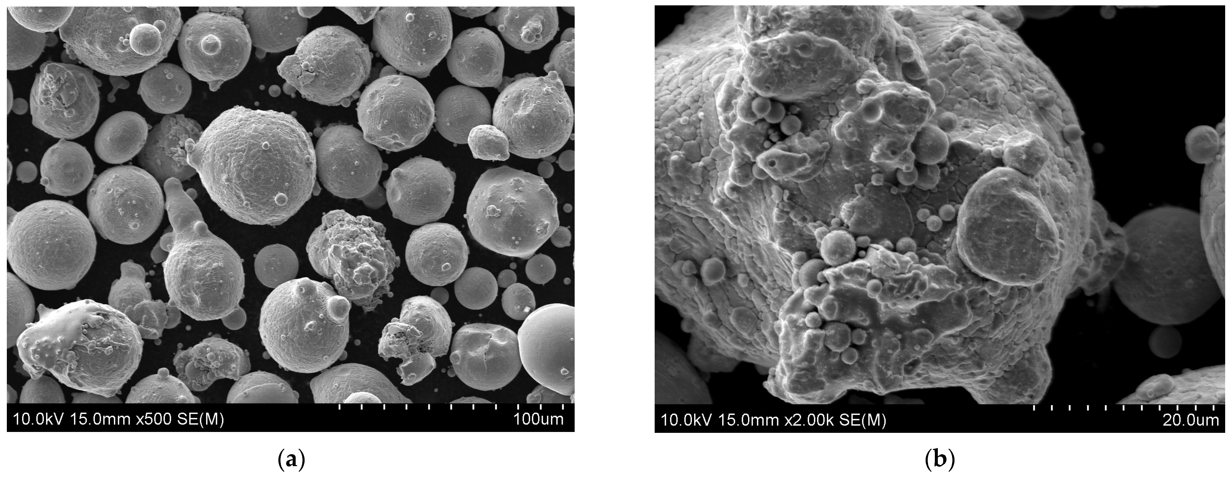
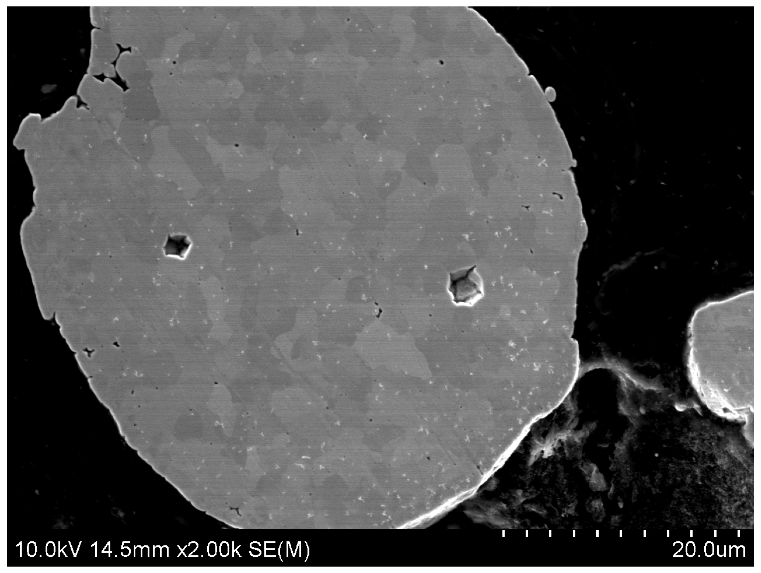
  • The sintering of the HEA powder at a temperature of 1050 °C and a compaction pressure of 50 MPa using the SPS method makes it possible to obtain specimens with a density similar to that of solid material, with a few fine pores uniformly distributed in the microstructure.
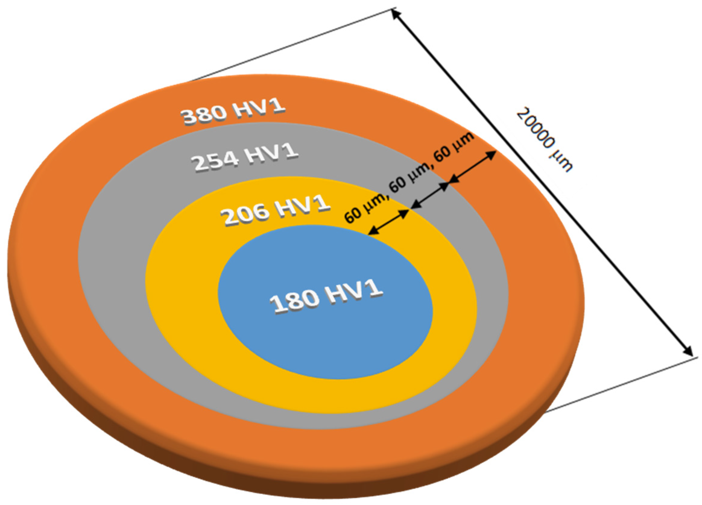
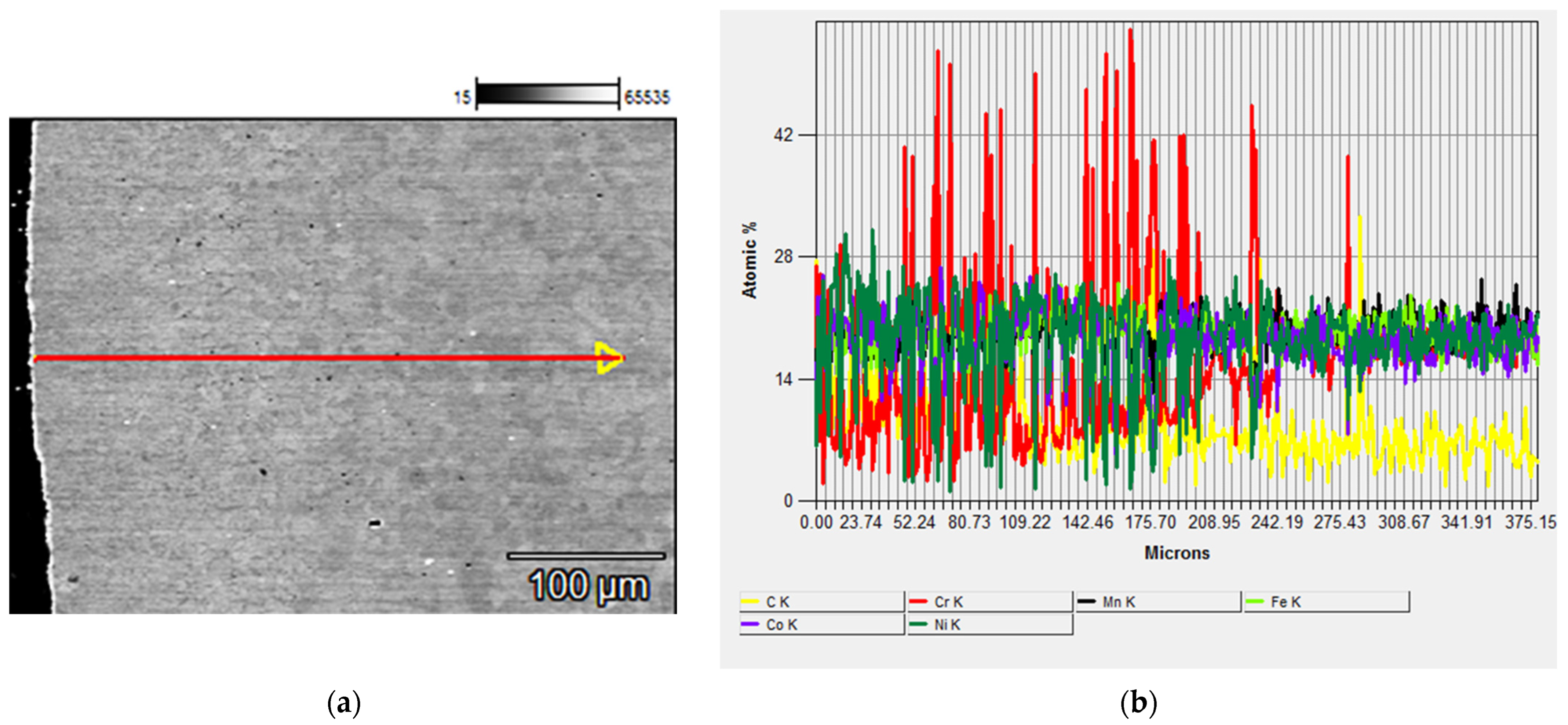
  • The hardness test on the surface and on the cross-section revealed significant differences depending on the location of the test. The hardness on the surface was, respectively, 402 HV1, while at a distance of over 180 μm, it decreased to 180 HV1.
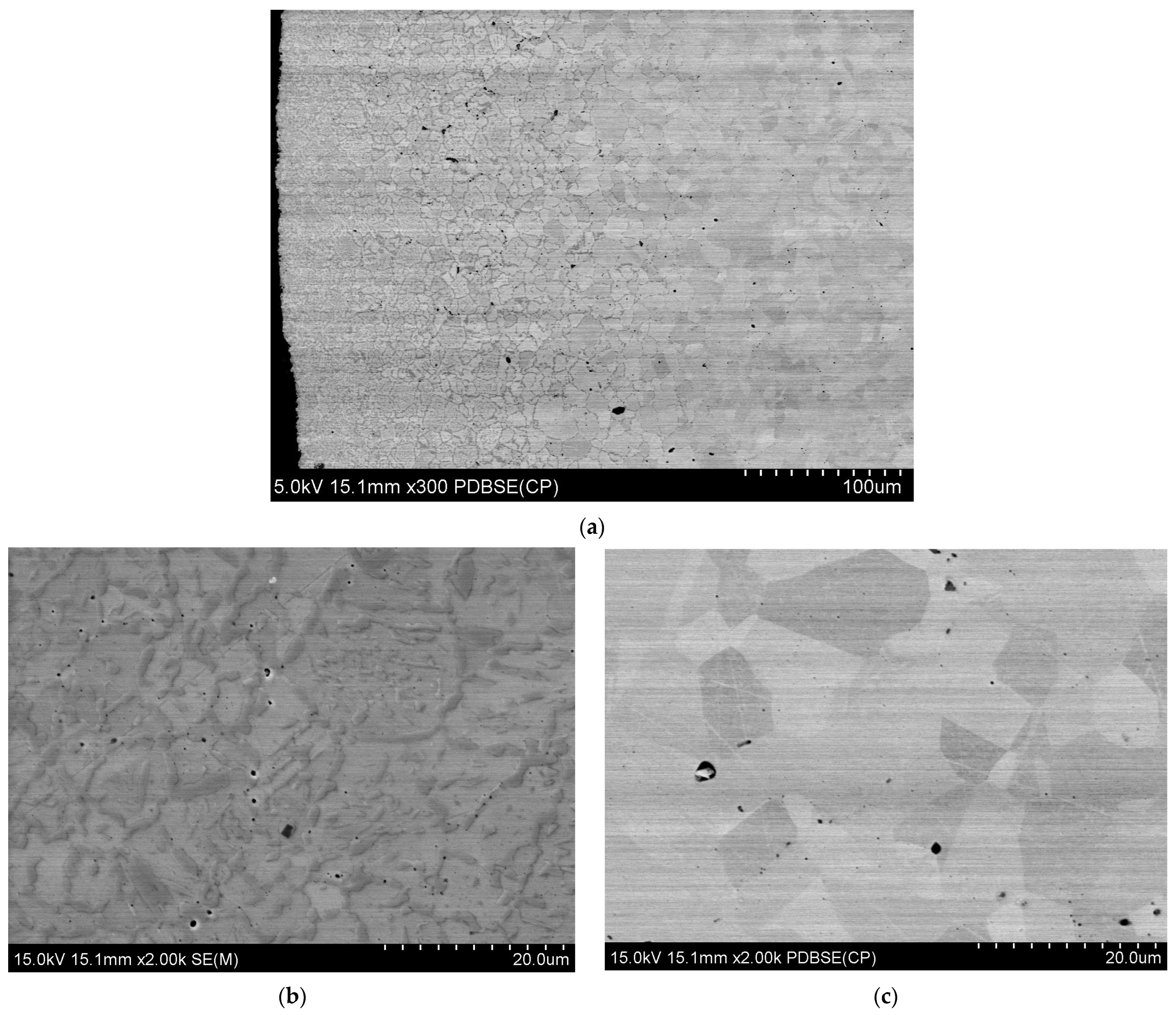
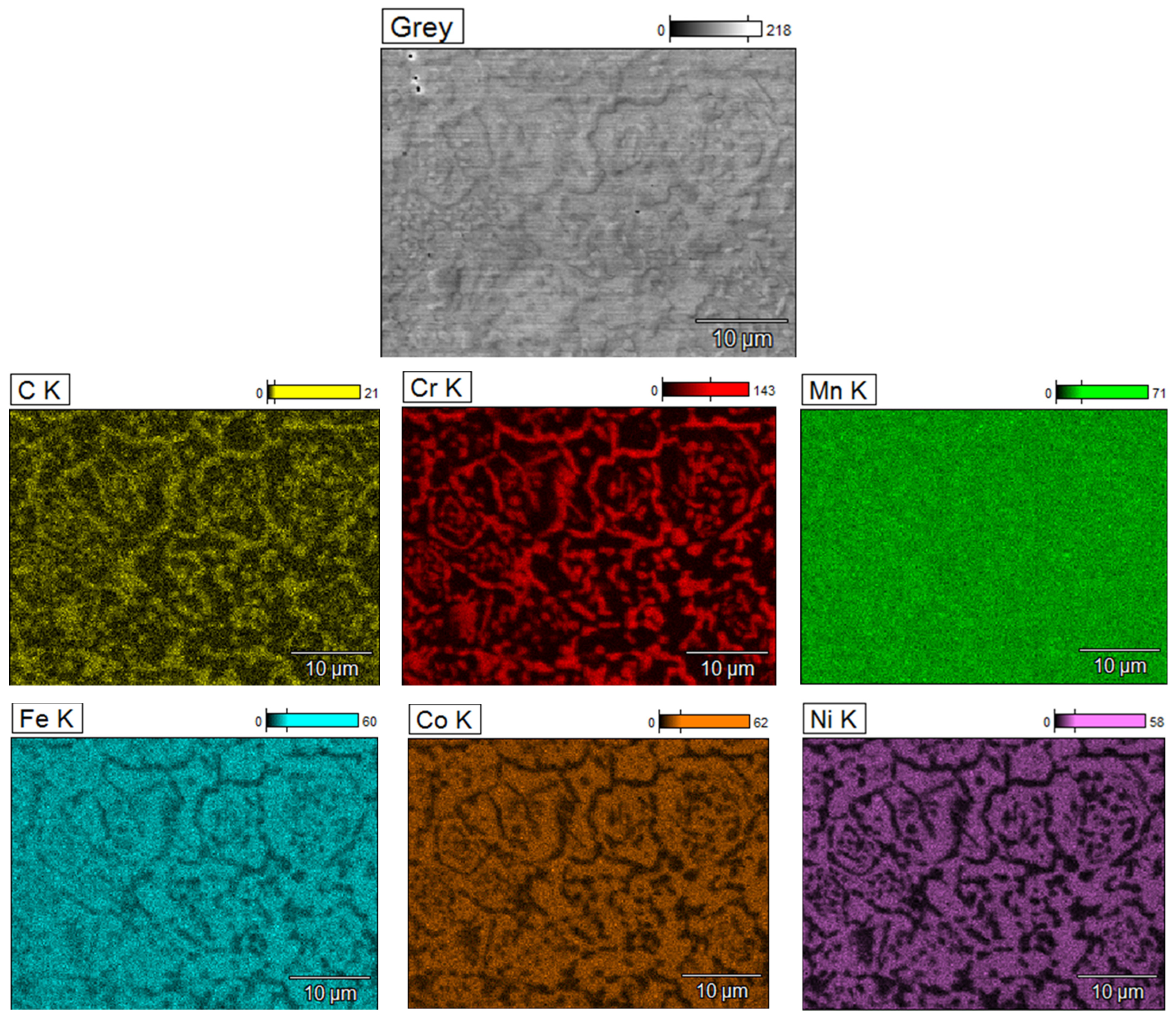
  • The observation of the microstructure showed changes in the top layer in relation to the core of the sintered material. The precipitate network was observed in the FCC phase boundaries.
  • The chemical composition analysis of the precipitates and X-ray diffraction confirmed that due to the carbon diffusion from the tool and chromium depletion of matrix grains, new Cr7C3- and Cr23C6-type chromium carbides were formed.
  • The quantity and size of carbides decreased with an increasing distance from the surface that was in contact with the graphite during the sintering process.

Author Contributions

Conceptualization, M.M.; methodology, M.M. and A.K.-S.; validation, M.M.; formal analysis, M.M.; investigation, M.M. and A.K.-S.; writing—original draft preparation, M.M.; writing—review and editing, M.M. and A.K.-S.; project administration, M.M. All authors have read and agreed to the published version of the manuscript.

Funding

This research did not receive external funding.

Institutional Review Board Statement

Not applicable.

Informed Consent Statement

Not applicable.

Data Availability Statement

Data are contained within the article.

Conflicts of Interest

The authors declare no conflict of interest.

References

  1. Cantor, B.; Chang, I.T.H.; Knight, P.; Vincent, A.J.B. Microstructural Development in Equiatomic Multicomponent Alloys. Mater. Sci. Eng. A 2004, 375, 213–218. [Google Scholar] [CrossRef]
  2. Yeh, J.W.; Chen, S.K.; Lin, S.J.; Gan, J.Y.; Chin, T.S.; Shun, T.T.; Tsau, C.H.; Chang, S.Y. Nanostructured High-Entropy Alloys with Multiple Principal Elements: Novel Alloy Design Concepts and Outcomes. Adv. Eng. Mater. 2004, 6, 299–303. [Google Scholar] [CrossRef]
  3. Tsai, K.Y.; Tsai, M.H.; Yeh, J.W. Sluggish Diffusion in Co–Cr–Fe–Mn–Ni High-Entropy Alloys. Acta Mater. 2013, 61, 4887–4897. [Google Scholar] [CrossRef]
  4. Yeh, J.W. Physical Metallurgy of High-Entropy Alloys. JOM 2015, 67, 2254–2261. [Google Scholar] [CrossRef]
  5. Zhang, Y.; Zuo, T.T.; Tang, Z.; Gao, M.C.; Dahmen, K.A.; Liaw, P.K.; Lu, Z.P. Microstructures and Properties of High-Entropy Alloys. Prog. Mater. Sci. 2014, 61, 1–93. [Google Scholar] [CrossRef]
  6. Cao, B.X.; Wang, C.; Yang, T.; Liu, C.T. Cocktail Effects in Understanding the Stability and Properties of Face-Centered-Cubic High-Entropy Alloys at Ambient and Cryogenic Temperatures. Scr. Mater. 2020, 187, 250–255. [Google Scholar] [CrossRef]
  7. Ye, Q.; Feng, K.; Li, Z.; Lu, F.; Li, R.; Huang, J.; Wu, Y. Microstructure and Corrosion Properties of CrMnFeCoNi High Entropy Alloy Coating. Appl. Surf. Sci. 2017, 396, 1420–1426. [Google Scholar] [CrossRef]
  8. Han, Z.; Ren, W.; Yang, J.; Tian, A.; Du, Y.; Liu, G.; Wei, R.; Zhang, G.; Chen, Y. The Corrosion Behavior of Ultra-Fine Grained CoNiFeCrMn High-Entropy Alloys. J. Alloys Compd. 2020, 816, 152583. [Google Scholar] [CrossRef]
  9. Gludovatz, B.; Hohenwarter, A.; Catoor, D.; Chang, E.H.; George, E.P.; Ritchie, R.O. A Fracture-Resistant High-Entropy Alloy for Cryogenic Applications. Science 2014, 345, 1153–1158. [Google Scholar] [CrossRef]
  10. Otto, F.; Dlouhý, A.; Pradeep, K.G.; Kubenova, M.; Raabe, D.; Eggeler, G.; George, E.P. Decomposition of the Single-Phase High-Entropy Alloy CrMnFeCoNi after Prolonged Anneals at Intermediate Temperatures. Acta Mater. 2016, 112, 40–52. [Google Scholar] [CrossRef]
  11. Li, L.; Li, Z. Aging Induced Segregation and Nanoprecipitation in a Severely Deformed Equiatomic High-Entropy Alloy. Mater. Charact. 2020, 165, 110369. [Google Scholar] [CrossRef]
  12. Stepanov, N.D.; Shaysultanov, D.G.; Ozerov, M.S.; Zherebtsov, S.V.; Salishchev, G.A. Second Phase Formation in the CoCrFeNiMn High Entropy Alloy after Recrystallization Annealing. Mater. Lett. 2016, 185, 1–4. [Google Scholar] [CrossRef]
  13. Hadraba, H.; Chlup, Z.; Dlouhy, A.; Dobes, F.; Roupcova, P.; Vilemova, M.; Matejicek, J. Oxide Dispersion Strengthened CoCrFeNiMn High-Entropy Alloy. Mater. Sci. Eng. A 2017, 689, 252–256. [Google Scholar] [CrossRef]
  14. Yang, T.; Cai, B.; Shi, Y.; Wang, M.; Zhang, G. Preparation of Nanostructured CoCrFeMnNi High Entropy Alloy by Hot Pressing Sintering Gas Atomized Powders. Micron 2021, 147, 103082. [Google Scholar] [CrossRef] [PubMed]
  15. Xu, J.; Wang, S.; Shang, C.; Huang, S.; Wang, Y. Microstructure and Properties of CoCrFeNi(WC) High-Entropy Alloy Coatings Prepared Using Mechanical Alloying and Hot Pressing Sintering. Coatings 2019, 9, 16. [Google Scholar] [CrossRef]
  16. Li, H.; Zhang, S.; Liang, J.; Hu, M.; Yang, Y. Effect of Ti on Characterization and Properties of CoCrFeNiTix High Entropy Alloy Prepared Via Electro-Deoxidization of the Metal Oxides and Vacuum Hot Pressing Sintering Process. Materials 2023, 16, 1547. [Google Scholar] [CrossRef] [PubMed]
  17. Nagarjuna, C.; Sharma, A.; Lee, K.; Hong, S.-J.; Ahn, B. Microstructure, Mechanical and Tribological Properties of Oxide Dispersion Strengthened CoCrFeMnNi High-Entropy Alloys Fabricated by Powder Metallurgy. J. Mater. Res. Technol. 2023, 22, 1708–1722. [Google Scholar] [CrossRef]
  18. Guo, Z.; Zhang, A.; Han, J.; Meng, J. Microstructure, Mechanical and Tribological Properties of CoCrFeNiMn High Entropy Alloy Matrix Composites with Addition of Cr3C2. Tribol. Int. 2020, 151, 106436. [Google Scholar] [CrossRef]
  19. Gwalani, B.; Pohan, R.M.; Waseem, O.A.; Alam, T.; Hong, S.H.; Ryu, H.J.; Banerjee, R. Strengthening of Al0.3CoCrFeMnNi-Based ODS High Entropy Alloys with Incremental Changes in the Concentration of Y2O3. Scr. Mater. 2019, 162, 477–481. [Google Scholar] [CrossRef]
  20. Yim, D.; Sathiyamoorthi, P.; Hong, S.J.; Kim, H.S. Fabrication and Mechanical Properties of TiC Reinforced CoCrFeMnNi High-Entropy Alloy Composite by Water Atomization and Spark Plasma Sintering. J. Alloys Compd. 2019, 781, 389–396. [Google Scholar] [CrossRef]
  21. Garbiec, D.; Rybak, T.; Heyduk, F.; Janczak, M. Zastosowanie urządzenia do iskrowego spiekania plazmowego SPS HP D 25. Modern Spark Plasma Sintering Device in Metal Forming Institute. Obróbka Plast. Met. 2011, XXII, 221–225. [Google Scholar]
  22. Ujah, C.O.; Von Kallon, D.V.; Aigbodion, V.S. High Entropy Alloys Prepared by Spark Plasma Sintering: Mechanical and Thermal Properties. Mater. Today Sustain. 2024, 25, 100639. [Google Scholar] [CrossRef]
  23. Moazzen, P.; Toroghinejad, M.R.; Cavaliere, P. Effect of Iron Content on the Microstructure Evolution, Mechanical Properties and Wear Resistance of FeXCoCrNi High-Entropy Alloy system Produced via MA-SPS. J. Alloys Compd. 2021, 870, 159410. [Google Scholar] [CrossRef]
  24. Colombini, E.; Rosa, R.; Trombi, L.; Zadra, M.; Casagrande, A.; Veronesi, P. High Entropy Alloys Obtained by Field Assisted Powder Metallurgy Route: SPS and Microwave Heating. Mater. Chem. Phys. 2018, 210, 78–86. [Google Scholar] [CrossRef]
  25. Laurent-Brocq, M.; Goujon, P.-A.; Monnier, J.; Villeroy, B.; Perrière, L.; Pirès, R.; Garcin, G. Microstructure and Mechanical Properties of a CoCrFeMnNi High Entropy Alloy Processed by Milling and Spark Plasma Sintering. J. Alloys Compd. 2019, 780, 856–865. [Google Scholar] [CrossRef]
  26. Tirumalasetty, G.K.; Fang, C.M.; Jansen, J.; Yokosawa, T.; Boeije, M.F.J.; Sietsma, J.; Van Huis, M.A.; Zandbergen, H.W. Structural Tale of Two Novel (Cr, Mn)C Carbides in Steel. Acta Mater. 2014, 78, 161–172. [Google Scholar] [CrossRef]
  27. Ye, W.; Xie, M.; Huang, Z.; Wang, H.; Zhou, Q.; Wang, L.; Chen, B.; Wang, H.; Liu, W. Microstructure and tribological properties of in-situ carbide/CoCrFeNiMn high entropy alloy composites synthesized by flake powder metallurgy. Tribol. Int. 2023, 181, 108295. [Google Scholar] [CrossRef]
Figure 1. SEM morphologies of HEA powders: (a) medium-sized particles; (b) particle with an expanded surface.
Coatings 14 00186 g001
Figure 2. Microstructure of HEA powder.
Coatings 14 00186 g002
Figure 3. Dependence of hardness on the distance from the sinter surface.
Coatings 14 00186 g003
Figure 4. Microstructure of the sintered HEA alloy: (a) the cross-section of the sample, (b) area near the outer surface, and (c) area inside the sinter.
Coatings 14 00186 g004
Figure 5. SEM: (a) Microstructure of sintered HEA powder and (b) analysis of elemental distribution along a line directed towards the center of the sample.
Coatings 14 00186 g005
Figure 6. Linear distribution of the elements: chromium (red) and carbon (yellow).
Coatings 14 00186 g006
Figure 7. Maps of the distribution of elements (C, Cr, Mn, Fe, Co and Ni) on the surface of as-sintered HEA powder.
Coatings 14 00186 g007
Figure 8. XRD pattern from as-SPS HEA powder.
Coatings 14 00186 g008
Table 1. Properties of the CoCrFeMnNi powder.
Chemical Composition (wt. %)
FeNiCrMnCo
19.6520.6717.8819.18Bal.
Oxygen content (ppm)438
Nitrogen content (ppm)139
Particle size distribution
D10/μmD50/μmD90/μm
21.634.453.7
Flowability (s)16.2
Bulk density (g/cm3)3.8
Microhardness (HV)155.93 ± 23
Disclaimer/Publisher’s Note: The statements, opinions and data contained in all publications are solely those of the individual author(s) and contributor(s) and not of MDPI and/or the editor(s). MDPI and/or the editor(s) disclaim responsibility for any injury to people or property resulting from any ideas, methods, instructions or products referred to in the content.

