Abstract
Nickel–tungsten (Ni-W) alloys are gaining significant attention due to their superior hardness, wear resistance, anti-corrosion and electrochemical hydrogen evolution reaction (HER) activity. In this work, porous and crack Ni-W alloys with different W contents were prepared in a pyrophosphate bath. The key to forming a porous structure is a very high current density over 300 mA cm−2. The HER activity of porous and crack Ni-W alloys was studied by means of electrochemical technologies of linear sweep voltammetry (LSV), Tafel curves (Taf) and electrochemical impedance spectroscopy (EIS). Compared with the crack Ni-W alloy, the porous Ni-W alloy exhibits improved alkaline electrochemical HER performances, which can deliver a current density of 10 mA cm−2 at 166 mV (η10) vs. RHE (reversible hydrogen electrode).
1. Introduction
High-purity hydrogen, an excellent renewable energy source, is usually obtained by an electrochemical hydrogen evolution reaction (HER) from water. Electrochemical water splitting is an effective way to produce hydrogen but requires efficient electrocatalysts [1,2,3,4,5]. An alkaline medium is suitable for industrial hydrogen production [6], because most transition metals and alloys substituted for Pt or other noble metals are relatively stable in the solutions [7]. However, compared with acidic solutions, alkaline HER is less efficient and more energy consumable due to higher overpotential requirement [7,8]. Therefore, the development of low-cost, highly active and durable catalysts for HER is crucial to produce mass hydrogen.
Nickel is a popular choice for alkaline HER catalysts, because it can almost meet the above requirements [7]. The HER performance of nickel can be further improved by forming heterostructures [7] and porous structures [9] and introducing single metals of Co [10,11,12], Cu [13], Mo [14,15], W [8,16,17,18,19] and binary metals of Co-Mo [20], Co-Sn [21], Cu-Mn [22] and W-Co [23] into Ni crystal lattice. The hydrogen evolution performance of nickel alloys is shown in Table 1.

Table 1.
Bath compositions and operation conditions for Ni-W alloys.
Dynamic hydrogen bubble template (DHBT) electrodeposition technology is facile and rapid in preparing porous metals [6,9]. Being different from the conventional electrodeposition process, the applied current of DHBT is higher in order to not only accelerate metal electrodeposition but also promote the side reaction of HER to produce numerous hydrogen bubbles. Growing and detached hydrogen bubbles are insulated, and metal is electrodeposited around the dynamic bubbles, consequently forming the special porous structures. Many porous metals and alloys for water splitting are fabricated by the DHBT method [6,9,13,15,22]. Although Ni-W catalyst HER performance has been extensively studied [8,16,17,18,23] electrodepositing porous Ni-W catalysts by DHBT has not been reported.
Electrodeposited Ni-W alloys are reported extensively as a candidate coating to replace the environmentally hazardous hexavalent hard chromium, because of excellent wear resistance and corrosion resistance [24]. Allahyarzadeh et al. [25] demonstrated enhanced HER activity and stability on electrodeposited Ni-W nanoparticles than Ni in 0.5 M H2SO4, decreasing the overpotential from 306 mV to 205 mV vs. RHE. In an alkaline medium, the Ni-W alloys are highly anticipated catalysts for industrial hydrogen production, as their excellent corrosion resistance allows for a much longer service span in the severe alkaline environment of HER [8,16,17,18,19,26]. Ni-W alloy HER activity fundamentally depends on the corresponding chemical composition, morphology, structure and physical–chemical properties, which can be adjusted by the nickel and tungsten salt concentration and electrodeposition parameters, such as pH, temperature and applied current density. The introduction of W into Ni crystal lattice is a factor of the improvement in the Ni HER activity through the synergistic effect of the combination of W and Ni [19], and the surface roughness is another factor by enhancing surface active sites [17]. Comparing three classes of alloys of electrodeposited Ni-W, Co-W and Fe-W, Vernickaite et al. [8] considered that Ni-29at. %W was the best electrocatalytic HER activity in 30 wt.% NaOH solution, presenting an exchange current density (ECD) of 0.55 mA cm−2 at 25 °C and 14.5 mA cm−2 at 65 °C. There is an enhancement in the surface roughness of electrodeposited Ni-W alloy films via an acidic solution etching treatment, and, thus, enhancement in their HER activity in an alkaline environment, and the overpotential is 169 mV (η10, at 10 mA cm−2) in 1.0 M KOH [17].
In this work, porous and crack Ni-W alloys with different W contents were electrodeposited on a carbon steel substrate in a pyrophosphate bath by adjusting the concentration of sodium tungstate and applied current density. The key to forming a porous structure is that a current density of over 0.3 A cm−2 is applied. The kinetics of the as-deposited electrodes for the HER in 1.0 M NaOH solution was estimated using Tafel curves and EIS spectra. The porous-structured Ni-W alloys with a high W content have great potential for application as an excellent alkaline HER electrocatalyst.
2. Experimental Section
2.1. Electrodeposition
The pyrophosphate bath, whose composition is listed in Table 1, was selected for electrodeposited Ni-W alloys on Q235 carbon steel disks with a diameter of 1.0 cm. Analytical reagents and deionized water were used to prepare the pyrophosphate bath.
Before electrodeposition, the Q235 carbon steel disks were welded with copper wire on one side, were then sealed with epoxy resin, polished orderly using Sic waterproof sandpapers of CW-600, CW-800 and CW-1000 to expose a smooth surface with 0.785 cm2, electrochemically degreased in 40 g L−1 NaOH solution at a current of 0.1 A cm−2 for 10 min, and lastly activated in 10% HCl solution for 10 s.
Ni-W alloys were electrodeposited on the pretreated Fe disks in 500 mL pyrophosphate bath using a DC power supply under a bath temperature of 55 °C. The bath pH was adjusted to 8.8~9.2 using NH3·H2O and diluted sulfuric acid. The content in Ni-W alloys was changed by tuning the concentration of NaWO4·2H2O and applied current density [27]. The electrodeposition time was set to 30 min. However, the edge effect resulting from electric field and electrochemical effects (such as the agglomeration of intermediate hydrogen radical at carbon steel) brought about rapid growth of Ni-W alloy crystal along the horizontal direction of carbon steel disks, and geometric area of the Ni-W films became bigger than carbon steel. Therefore, the electrodeposition time was shortened to 5 min for HER activity evaluation.
After electrodeposition, the carbon steel coated with Ni-W alloy was rinsed using deionized water and further ultrasonically cleaned in deionized water for 10 min. It was then immersed in 1.0 M NaOH solution for subsequent electrochemical tests or dried for subsequent characterization.
2.2. Characterization
Surface morphology and structural properties of as-deposited Ni-W alloy catalysts, as well as their elemental composition, were analyzed by scanning electron microscopy (SEM, SU3500, Hitachi, Tokyo, Japan) and energy-dispersive spectroscopy (EDS, One Max 20, Tuscan, Oxford, UK, d = 1 nm, 100×), respectively. The crystal structures for all samples were characterized by X-ray diffraction (XRD, Empyren, PANalytical, Shanghai, China) in the 2θ range of 20 to 100° at a scan rate of 4° min−1 using Cu Kα radiation (λ = 0.15406 nm). Surface element valence distribution was determined using X-ray photoelectron spectroscopy (XPS, AXIS SUPRA+, Shimadzu, Kyoto, Japan). The obtained XPS spectra were calibrated with respect to C 1s (284.5 eV) and fitted with Casa XPS software.
2.3. Electrocatalytic Evaluation
As-deposited Ni-W alloys as working electrode and a Pt square piece (1 cm × 1 cm) as counter electrode were, respectively, put into two containers filled with 1.0 M NaOH and linked by a porous ceramic sheet. The saturated KCl solution containing 0.02 wt.% agar was carefully and rapidly added into the third container to its half volume under 90 °C via the upper bottle mouth and then filled with the saturated KCl solution after forming gel at room temperature. A saturated calomel electrode (SCE) as reference electrode was inserted into the above saturated KCl solution. The bottom sharp mouth of the third carriage pointed to working electrodes to reduce the solution resistance effect during electrochemical measurement. Electrochemical active surface area (ECSA) was measured by cyclic voltammetry (CV) at scan rates of 10 to 100 mV s−1 between ±50 mV and RHE. The potential E (vs. RHE, reversible hydrogen electrode) was calculated according to the following formula [28].
E (vs. RHE) = E (vs. SCE) +ESCE (0.241 V) + 0.0592 × pH
The electrocatalytic activities of all deposits for HER were evaluated by means of linear sweep voltammetry (LSV) at a scanning rate of 10 mV s−1 and electrochemical impedance spectroscopy (EIS) in the range of 100 kHz to 0.2 Hz with 5 mV amplitude at a potential of 230 mV vs. RHE in aforementioned 1.0 M NaOH solution at room temperature. Electrical equivalent circuit corresponding to the EIS analysis was fitted with the Zview software. All of the electrochemical studies were carried out in three containers with an electrochemical workstation (CHI660E, Shanghai Chenhua Instrument Co., Ltd., Shanghai, China).
3. Results and Discussion
3.1. Characterization of Ni-W Alloys
The material’s electrocatalytic activity relies on its surface roughness, which increases the specific surface area available for the HER. The surface morphology of electrodeposited Ni-W alloys is significantly influenced by the applied current density (CD), thereby modulating their HER performance. The microstructural evolution of Ni-W alloys electroplated in a pyrophosphate bath containing 50 g L−1 Na2WO4·2H2O with varying applied current densities is depicted in Figure 1. As shown in Figure 1a, the Ni-W alloy coating formed at 0.1 A cm−2 displays a cracked surface consisting of polygons with areas of approximately 1 mm2. Conversely, as the applied current density (CD) exceeds 0.3 A cm−2, the surface morphology exhibits a noticeable change compared to the Ni-W alloy deposited at a lower CD of 0.1 A cm−2. Many pores can be observed in Figure 1b,c, which are caused by hydrogen bubbles generated during electrodeposition. At the same time, the cracks disappear due to the release of stress by the pores. Increasing CD could accelerate the reaction processes of both metal electro-crystallization and hydrogen evolution, resulting in hydrogen bubbles rapidly growing during their short dwelling period on the surface, and alloy crystal rapid growth occurred only around the hydrogen bubbles. Hence, pores or pits were left behind after the separation of hydrogen bubbles. The size of pores was determined by the growth and separation of hydrogen bubbles. The dynamic hydrogen bubble template (DHBT) was used to prepare other porous metal, for example, porous Ni deposits at higher CD of 1 Acm−2 under ultrasound-assisted condition [9], porous Ni-Mo alloy deposits at high CD of over 0.6 Acm−2 under super gravity field [15]. The condition of porous structures is under a high CD, usually over 0.6 Acm−2 [5,9,13,15,22]. The low CD for forming porous Ni-W alloys could be attributed to the high bath pH and low current efficiency (Figure 2) in the present system. The current efficiency calculation formula is as follows:
m: For the actual product quality. I: Current of electrodeposition. t: Time of the electrodeposition. k1, k2: Electrochemical equivalent of Ni and W.
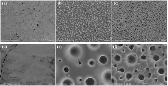
Figure 1.
SEM images of Ni-W alloys electrodeposited from the bath containing 50 g L−1 Na2WO4·2H2O at different current density of (a) 0.1 A cm−2, (b) 0.3 A cm−2 and (c) 0.6 A cm−2 for 30 min, and (d–f) are the magnified images, respectively.

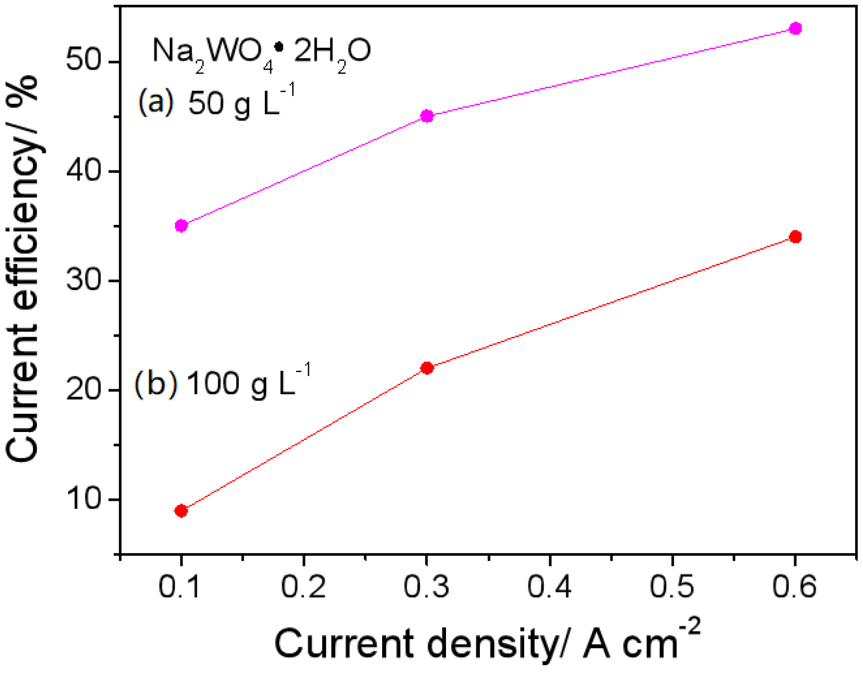
Figure 2.
Current efficiency of Ni-W alloy electrodeposited from the baths of (a) 50 g L−1 and (b) 100 g L−1 Na2WO4·2H2O at 0.1, 0.3 and 0.6 A cm−2.
As shown in Figure 1b, the port density is about 760 pores per square centimeter (760 n cm−2) and the pore size is between 50 μm and 200 μm. Increasing the applied CD to 0.6 Acm−2, the pore density can be further improved to about 1470 n cm−2 (see Figure 1c), and the pore range is still from 50 μm to 200 μm. From the magnified images shown in Figure 1c–e, it can be seen that the Ni-W alloy crystal itself is all smooth, and branch structures or flower-like structures have not been formed.
It is well known that the electrodeposition of pure W is not possible, but it can be electrodeposited by the inducement of Ni or other iron group elements. As a result, the current efficiency of the Ni-W alloy is decreased along with the tungstate concentration in the electrolyte. This phenomenon is also observed in the pyrophosphate bath. As shown in Figure 2, the current efficiency is lower at 100 g L−1 than at 50 g L−1Na2WO4·2H2O under the corresponding CD. The lower the current efficiency, the more hydrogen bubbles; the lower the current efficiency, the more hydrogen bubbles and the more conducive. Therefore, the preparation of porous Ni-W should be conducted under conditions of high current density and a high tungstate concentration. Additionally, a short electrolysis time of 5 min was chosen to prevent the formation of Ni-W alloy films that are much larger in geometric area than the substrate carbon steel disk, due to edge effects.
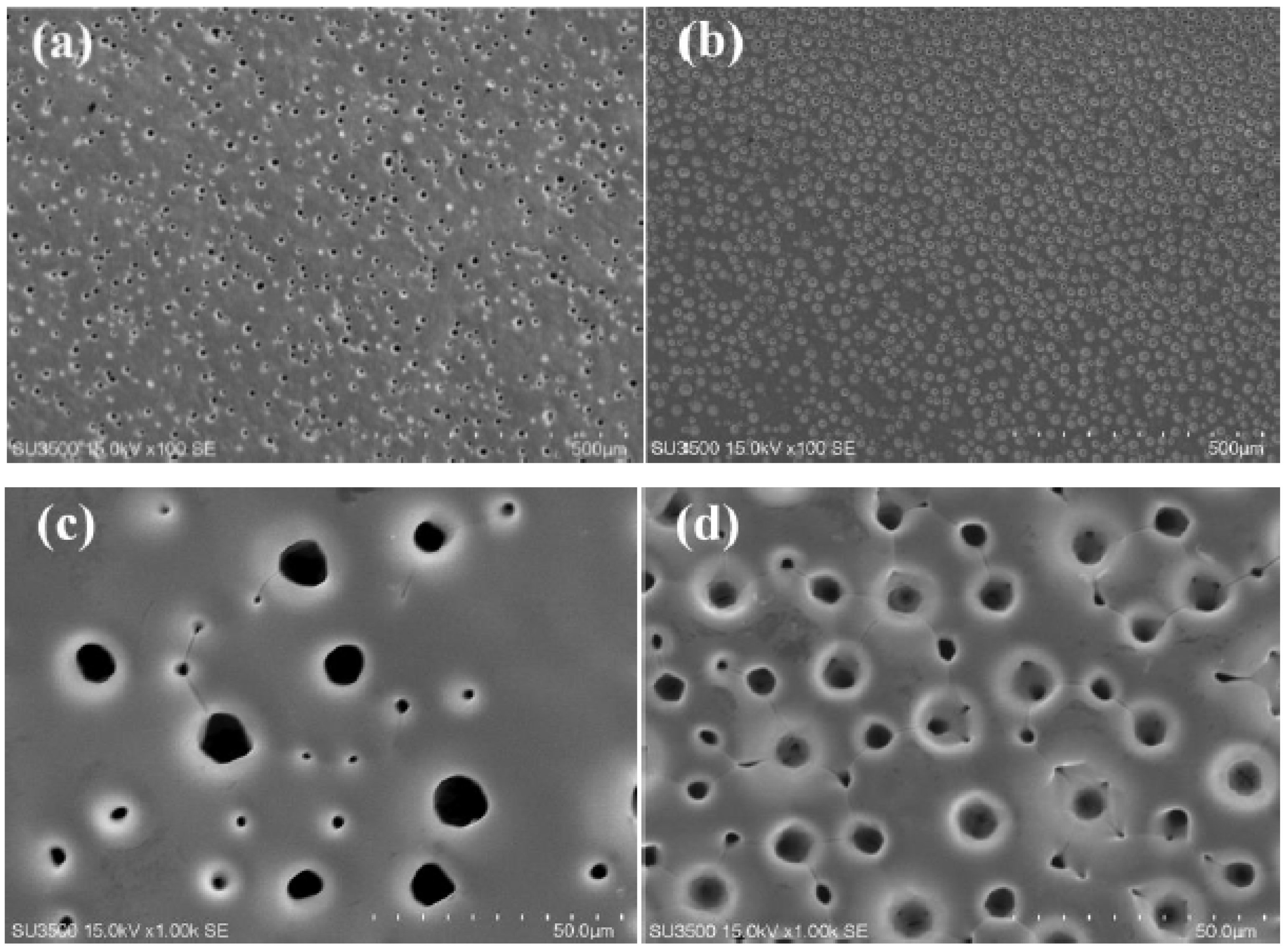
SEM images of porous Ni-W alloys electrodeposited at 0.6 Acm−2 for 5 min from the bath containing 50 g L−1 (named PNiW5-6) and 100 g L−1 (named PNiW10-6) Na2WO4·2H2O are shown in Figure 2. It is observed that porous structures can be formed in such a short period of time and the pore density of PNiW10-6 is about 2-times that of PNiW5-6. The result implies that the PNiW10-6 sample possesses better electrocatalytic activity. From Figure 3b,d, it is found that the pore density increased to about 3100 n cm−2, indicating that the bubbles attached and separated from the surface of the Ni-W alloy reach a dynamic equilibrium after 5 min. In addition, the pore size range of PNiW10-6 is relatively narrow; that is, the pores sizes are from 20 to 120 μm. For a comparison of the alkaline HER performance, the crack Ni-W alloy electrodeposited at a low CD of 0.1 Acm−2 (named CNiW10-1) was also prepared. The electrodeposition parameters are listed in Table 2. To ensure a film thickness of over 5 μm, the electrodeposition time for CNiW10-1 was prolonged to 30 min. SEM images of a profile view of porous Ni-W alloy electrodeposited at 0.6 A cm−2 for 5 min from the bath of 100 g L−1 Na2WO4·2H2O and the model of DHBT are shown in Figure 4. As the bubbles grow, their diameters gradually increase. The creation of bubbles on the surface of an electrode involves three steps: nucleation, growth and detachment. When hydrogen dissolved in a solution comes into contact with the electrode surface, nucleation and growth begin, and during the growth process, the contact angle gradually decreases until detachment. At each hydrogen bubble nucleation site, a portion of the gas remains after the bubble is detached, allowing the next bubble to continue to evolve and grow in situ.

Figure 3.
SEM images of porous Ni-W alloys electrodeposited at 0.6 A cm−2 for 5 min from the baths of (a) 50 g L−1 Na2WO4·2H2O, named PNiW5-6, and (b) 100 g L−1 Na2WO4·2H2O, named PNiW10-6, and (c,d) are the magnified images, respectively.
Table 2.
Electrodeposition conditions for three samples.
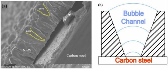
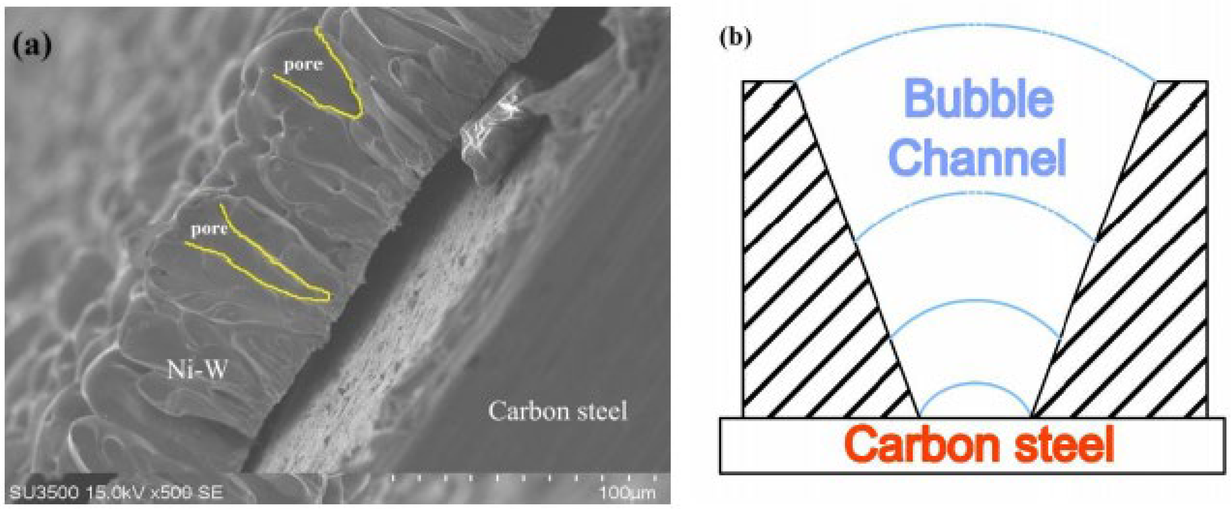
Figure 4.
(a) SEM images of profile view of PNiW10-6 and (b) the model of formation of pores.
In the process of generating bubbles, due to gas insulation, the Ni-W alloy along the bubble grew, and, with the growth of bubbles, the radius gradually increased, leading to the formation of the V-shaped profile shown in Figure 4b. Due to the insulating properties of the bubbles, the coating grows along with the bubbles, and the change in bubble diameter leads to a corresponding change in pore diameter, as depicted in Figure 4a.
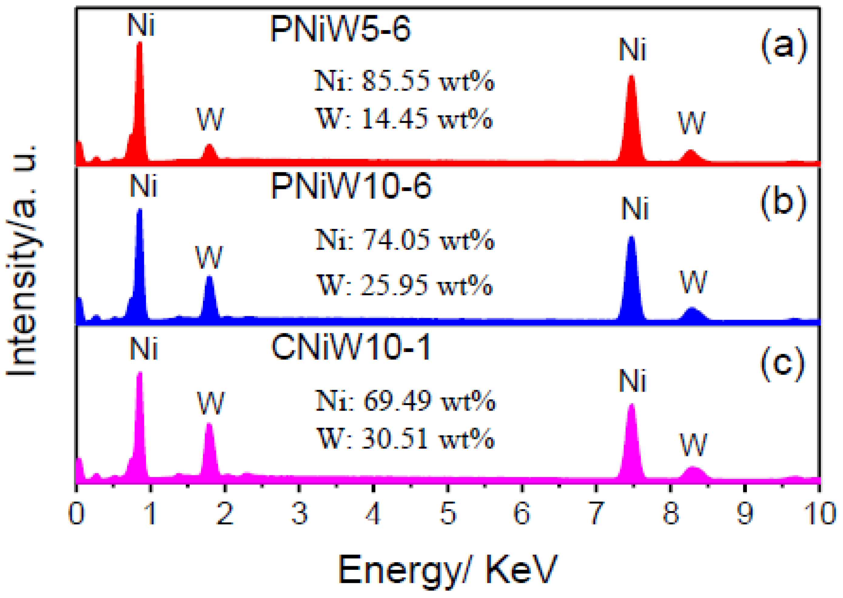
The composition of three samples was analyzed by EDS, and the results are shown in Figure 5. The characteristic peaks of the Ni and W elements all appear, indicating that the co-deposition of Ni and W occurred in the pyrophosphate bath [27]. The content of W in Ni-W alloy coatings is improved from 14.45 wt.% of the PNiW5-6 sample to 25.96 wt.% of the PNiW10-6 sample, when the concentration of Na2WO4·2H2O is enhanced from 50 to 100 g L−1. The W content can be further improved to 30.51 wt.% of the CNiW10-1 sample by decreasing applied CD, but surface cracks appear, as shown in Figure 1a.
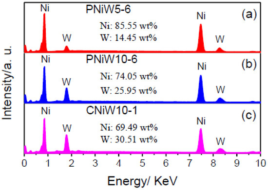
Figure 5.
EDX spectra of (a) PNiW5-6, (b) PNiW10-6 and (c) CNiW10-1 samples.
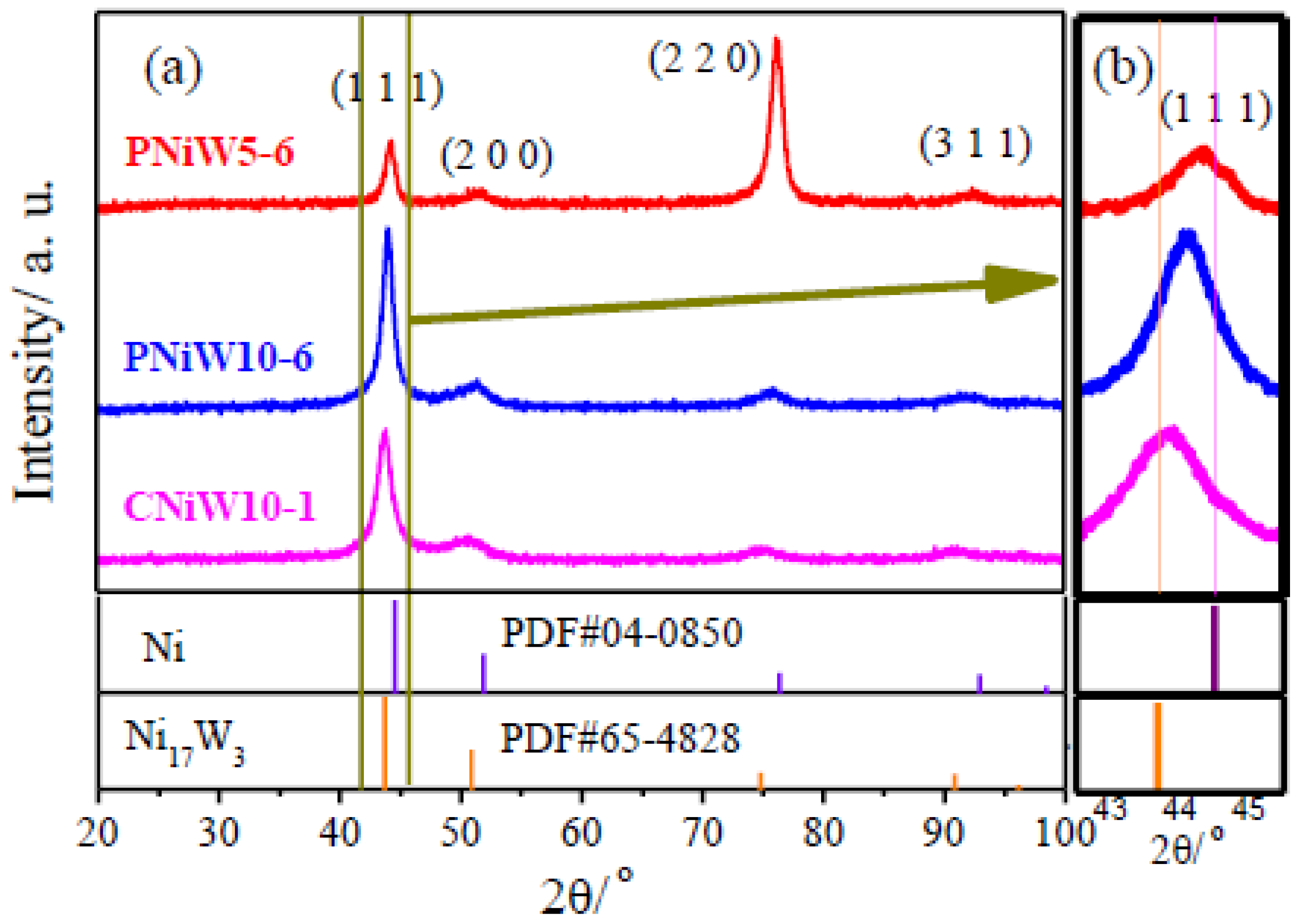
Figure 6 shows XRD patterns of porous Ni-W alloys of PNiW5-6 and PNiW10-6 as well as the crack Ni-W alloy of CNiW10-1. It can be seen in Figure 5a that the Ni-W coatings present diffraction peaks at 2θ of about 44°, 51° and 76°, corresponding to the three standard diffraction peaks of pure FCC nickel (JCPDS No: 04-0850). As shown in Figure 5a, all peak position shifts towards a low angle, suggesting the lattice shrinkage of nickel because of the introduction of large atoms into the Ni matrix. From the amplified XRD patterns shown in Figure 5b, the negative shift in the (1 1 1) diffraction peak can be clearly observed for three samples but always on the right of Ni17W3 (JCPDS No: 65-4828, the W content is 34.61 wt.%), suggesting that the W content in PNiW5-6, PNiW10-6 and CNiW10-1 samples is all lower than 34.61 wt.%, which is consistent with that of EDS data. Compared to the XRD patterns of CNiW10-1 with crack morphology and CNiW10-1 with a porous structure, it can be concluded that their crystal structures are very similar; that is, the crystal structure of the Ni-W alloy is independent of the surface microstructure. The crystal structure of Ni-W alloys can be altered by varying the W content, with even the W-rich Ni-W alloys capable of transforming into an amorphous state [24]. The PNiW5-6 sample presents a preferred orientation of (2 2 0), whose W content is only 14.45 wt.%.
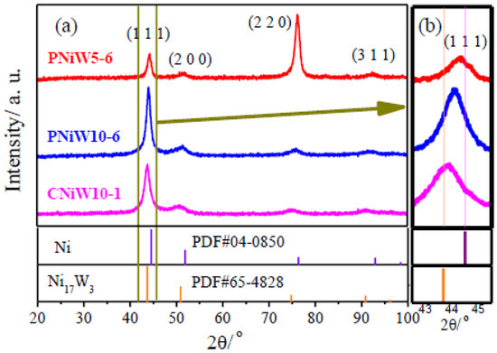
Figure 6.
(a) XRD patterns of porous Ni-W alloys of the PNiW5-6 and PNiW10-6, and crack Ni-W alloy of CNiW10-1, and (b) the corresponding magnified patterns.
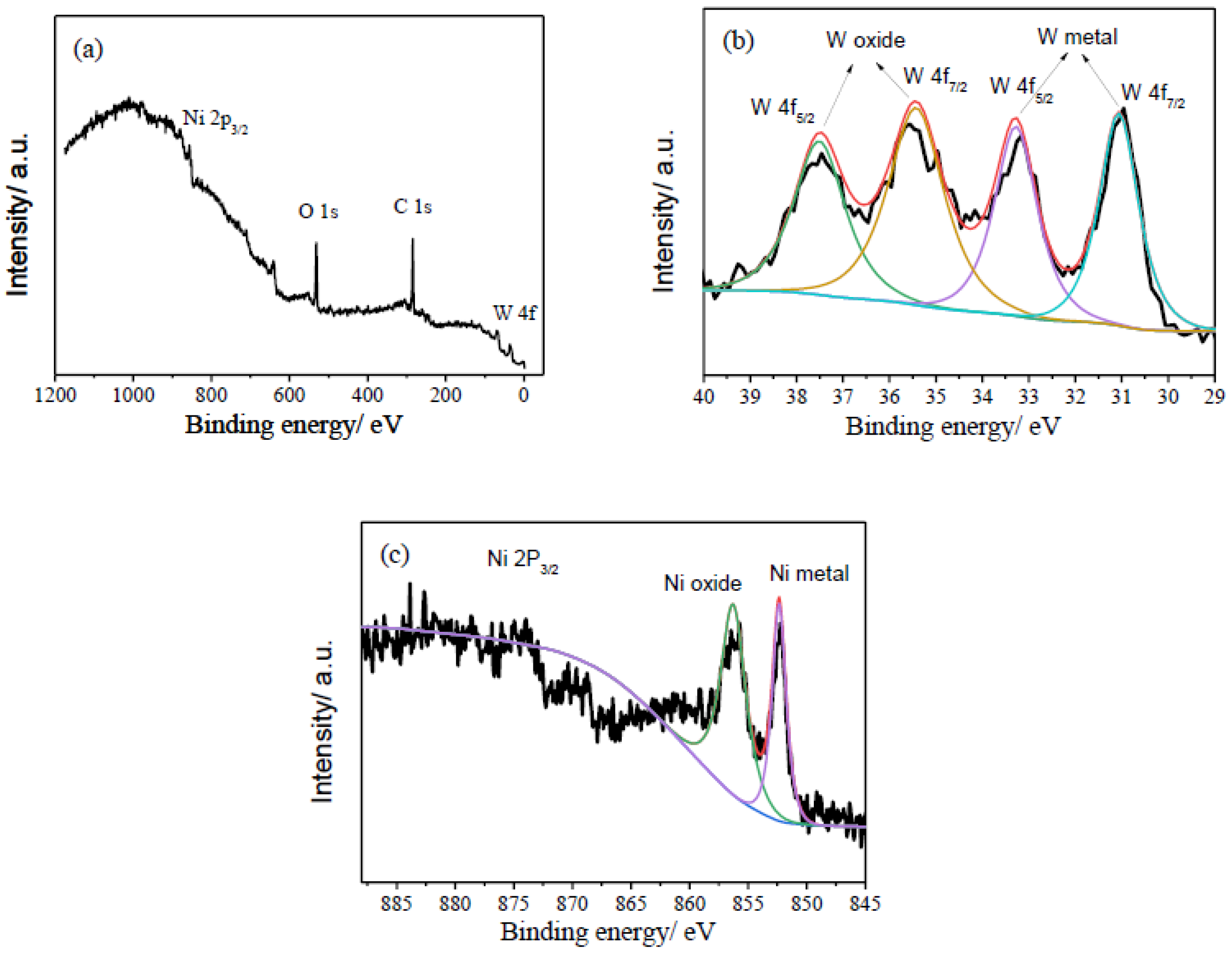
XPS was performed to analyze the composition and chemical states of the PNiW10-6 sample, and the results are shown in Figure 7. As shown in Figure 6a, the sharp signals of O 1s and C 1s and weak peaks of Ni 2P and W 4f are detected in the XPS full spectrum, likely because of the existence of the adsorption of CO2 or the formation of oxides on the surface of the porous Ni-W alloy. In Figure 7b, the high-resolution W 4f XPS spectrum presents four peaks at 31.06 eV and 33.26 eV for the W metal [29,30] and 35.46 eV and 37.46 eV for the tungsten oxides of NiWO4 or WO3 [19,29,30]. For Ni 2P 3/2, two peaks centered at 852.48 eV and 856.27 eV are assigned to the Ni metal and Ni2+, respectively [29,30]. Therefore, the W4f and Ni 2P XPS spectrum of the PNiW10-6 sample shows that surface Ni and W are both in an oxidized (in the form of Ni2+ and W6+, respectively) and atom state.
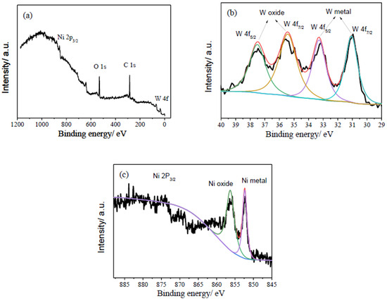
Figure 7.
XPS spectra of (a) full survey, (b) W4f, (c) Ni2P of the PNiW10-6 sample.
3.2. Electrocatalytic Properties
The alkaline HER activities of porous and cracked Ni-W alloys were evaluated through LSV analysis and corresponding Tafel plots in a 1.0 M NaOH solution. Comparative studies were conducted on a carbon steel substrate (named Fe) and a Pt disk (with a diameter of 5 mm), under identical experimental conditions.
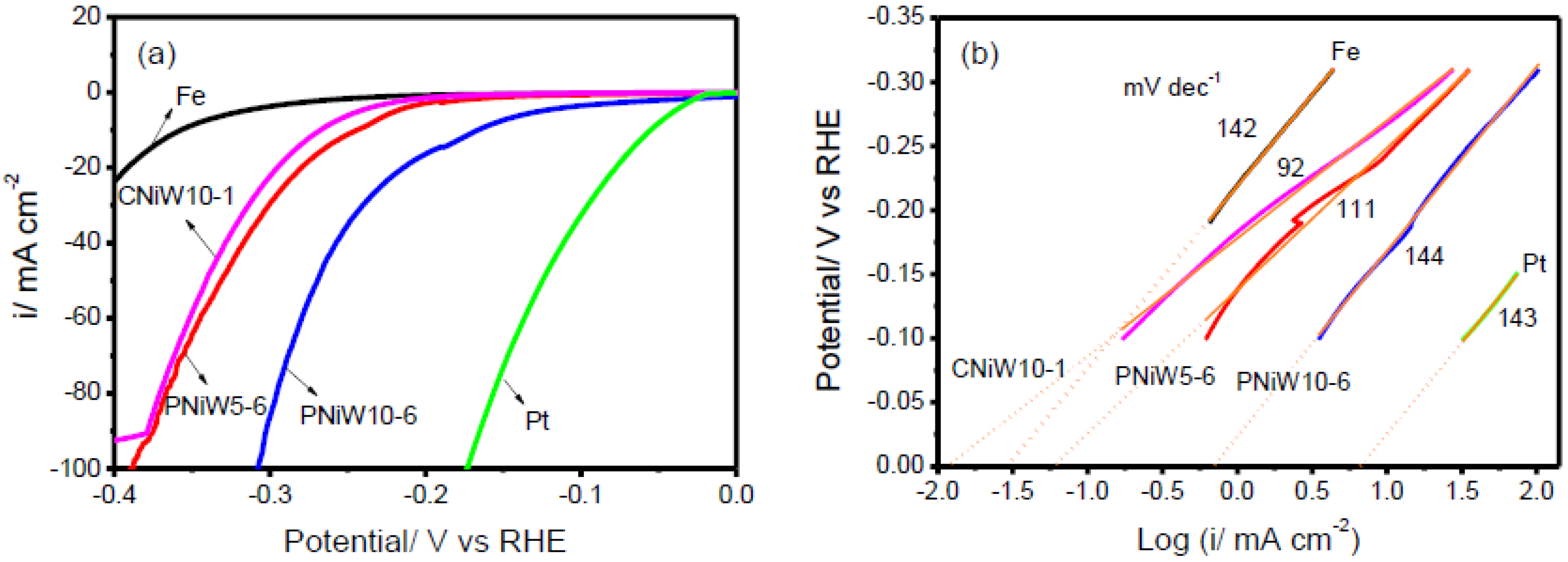
Figure 8a shows the LSV curves of three Ni-W alloy catalysts, the Fe and Pt disk after iR correction. Obviously, the Pt electrode exhibits superior electrocatalytic activity. As expected, the Fe electrode presents the poorest alkaline HER performance. In comparison with PNiW5-6, PNiW10-6 possesses greater electrocatalytic activity, attributed to a higher pore density, higher W content and the synergistic effect of nickel and tungsten.
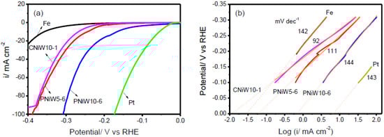
Figure 8.
(a) Linear sweep voltammetry (LSV) curves recorded on the PNiW5-6, PNiW10-6 and CNiW10-1 electrodes in 1.0 M NaOH solution at a scan rate of 10 mV s−1; for comparison, the Fe and Pt electrodes are also given. (b) The corresponding raw and fitted linear Tafel polarizati.
The PNiW10-6 catalyst can deliver cathodic current densities of 10, 20, 50 mA cm−2 at overpotentials of 166 mV (η10), 213 mV (η20), and 269 mV (η50), respectively, which is higher than that of electrodeposited Ni-W alloy enhanced by Ni selective etching [17]. For example, the best η10 is 169 mV in Table 3. In addition, it is accomplished by electrochemical deposition in one step, i.e., electrochemical deposition followed by etching, which has the advantages of a simple operation process and fast preparation and amorphous Ni-W alloys electrodeposited from an ammonium-citrate bath [18], for example, η10 > 200 mV. Overpotential values of all electrodes are given in Table 4. The crack CNiW10-1 sample without a porous structure possesses the highest W content, but it shows relatively poor activity, presenting η10, η20 and η50 of 267 mV, 295 mV and 341 mV, respectively. Therefore, it can be concluded that forming a porous structure is an effective path to enhance the catalytic activity for alkaline HER.
Table 3.
HER kinetic parameters in the literature.
Table 4.
HER kinetic parameters of all experimental electrode.
Due to the lack of H+, the HER in an alkaline environment starts from dissociating H2O molecules. Three reactions of Volmer, Heyrovsky and Tafel are as follows [7,20,22].
The rate-determining steps of the HER mechanism can be determined by means of a Tafel slope. The Tafel slopes of 120 mV dec−1, 40 mV dec−1 and 30 mV dec−1 correspond to the Volmer, Heyrovsky and Tafel rate-determining steps, respectively. Figure 7b shows the raw and fitted linear Tafel plots derived from LSV examination, and the fitted Tafel parameters are listed in Table 4. The Tafel slope of all experimental electrodes in the present 1.0 M NaOH solution is close to 120 mV dec−1, suggesting that the Volmer reaction is the rate-determining step, where many adsorbed hydrogen atoms cover the surface of catalysts. The Volmer rate-determining step for other electrodeposited Ni-W alloys is also demonstrated [8,17,18]. The HER catalytic ability is usually assessed by the exchange current density (ECD), which is the rate of hydrogen evolution per surface area at the equilibrium electrode potential [8]. ECD is obtained by extending linear Tafel plots to η = 0 mV. As shown in Figure 8b and Table 3, the ECD (i0) of the CNiW10-1 catalyst with a crack structure is 0.012 mA cm−2, which is slightly lower than the reported values in the 30 wt.% NaOH solution, 0.024 mA cm−2 for Ni-5at. %W (13.63 wt.%) and 0.073 for Ni-20at. %W (42.86 wt.%) [8]. But the PNiW5-6 catalyst with a low W content of 14.45 wt.% presents a bigger value of 0.062 mA cm−2 in comparison with the reported Ni-5at. %. Increasing the W content to 30.51wt.%, the ECD of the PNiW10-6 is greatly improved to 0.741 mA cm−2, which is higher than that of Ni-29 at. %W [8]. The good catalytic ability can be attributed to their porous structures.
The porous structures possess a high specific surface area, which can provide a greater electrochemically active surface area (ECSA) of each catalyst and consequently enhance catalytic performances. The ECSA was estimated from the double-layer capacitance (Cdl) of the catalytic surface by means of the cyclic voltammetry (CV) in a non-Faradaic potential region at different scan rates. Cdl was obtained according to the slope of the following equation, Equation (6) [20,32].
where is the difference in forward and backward scan current densities at a particular potential in CV curves, ν is the scan rates (10–120 mV/s), the half of the straight-line slope of Δi against ν is Cdl. And the ECSA of each catalyst sample is calculated according to Equation (7).
where Cs is the specific capacitance of an atomically smooth planar surface. In 1.0 M NaOH solution, Cs is typically taken as 0.040 mF cm−2 [32]. Figure 9 shows CVs of three Ni-W alloy samples and blank Fe and Pt electrodes. As expected, PNiW10-6 exhibits a maximum Cdl of 38.23 mF cm−2 and the ECSA was calculated as 955.75 cm2. The substrate of the Fe disk polished by waterproof sandpapers of CW-1000 has an ECSA of 73.50 cm2, much larger than its geometric area of 0.79 cm2. With respect to the Fe substrate, the ECSA of PNiW10-6, PNiW5-6 and CNiW10-1 was increased by 13.0-times, 2.9-times and 1.4-times, respectively.
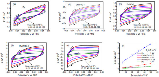
Figure 9.
Cyclic voltammetry (CV) curves recorded on the (a) Fe, (b) CNiW10-1, (c) PNiW5-6, (d) PNiW10-6 and (e) Pt electrodes in 1.0 M NaOH solution between −0.05 and 0.05 V at different scan rates of 10, 20, 40, 60, 80 and 100 mV s−1. (f) The relationship between the difference of positive and negative scan current at 0 V (2 Δi) and scan rate, the calculated Cdl according to the corresponding slope is also shown.
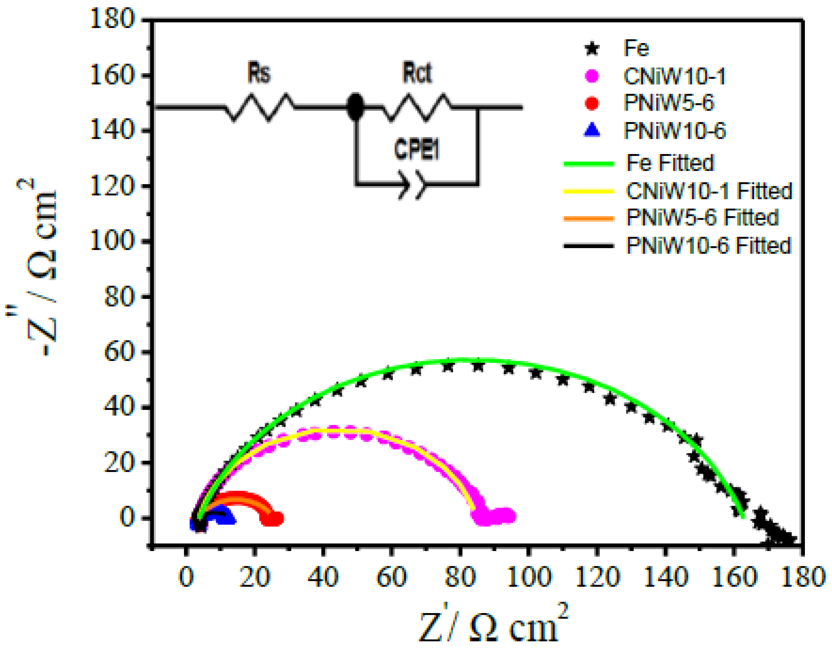
The enhanced alkaline HER activity mechanism was further investigated via an EIS test at an overpotential of 230 mV, where numerous hydrogen bubbles detached from the surface of catalysts. As shown in Figure 9, one compressed semicircle is observed in all Nyquist plots, indicating that all samples underwent the same electrochemical reaction process. An equivalent circuit model with one time constant shown in the insert was utilized to fit the Nyquist plots, and the results are listed in Table 5. The diameter of the semicircle indicates the polarization or charge transfer resistance (Rct), Rs is solution resistance and CPE-T is constant phase element (CPE), being related to Cdl. As seen from Figure 10 and Table 5, the Rct of the reaction at PNiW10-6 is 9.30 Ω cm2, which is lower than that of at PNiW5-6 (22.07 Ω cm2), and much lower than that of at the crack CNiW10-1 sample (80.38 Ω cm2) and the Fe substrate (124.84 Ω cm2), suggests that the PNiW10-6 electrode possesses the fastest HER kinetics.
Table 5.
Electrical equivalent circuit parameters.
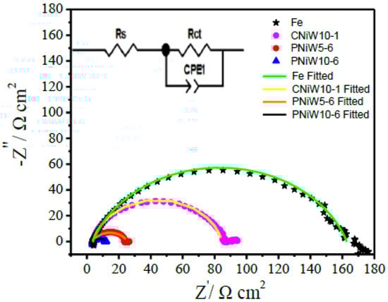
Figure 10.
Nyquist plots of the CNiW10-1, PNiW5-6 and PNiW10-6 electrodes at 230 mV in 1.0 M NaOH solution.
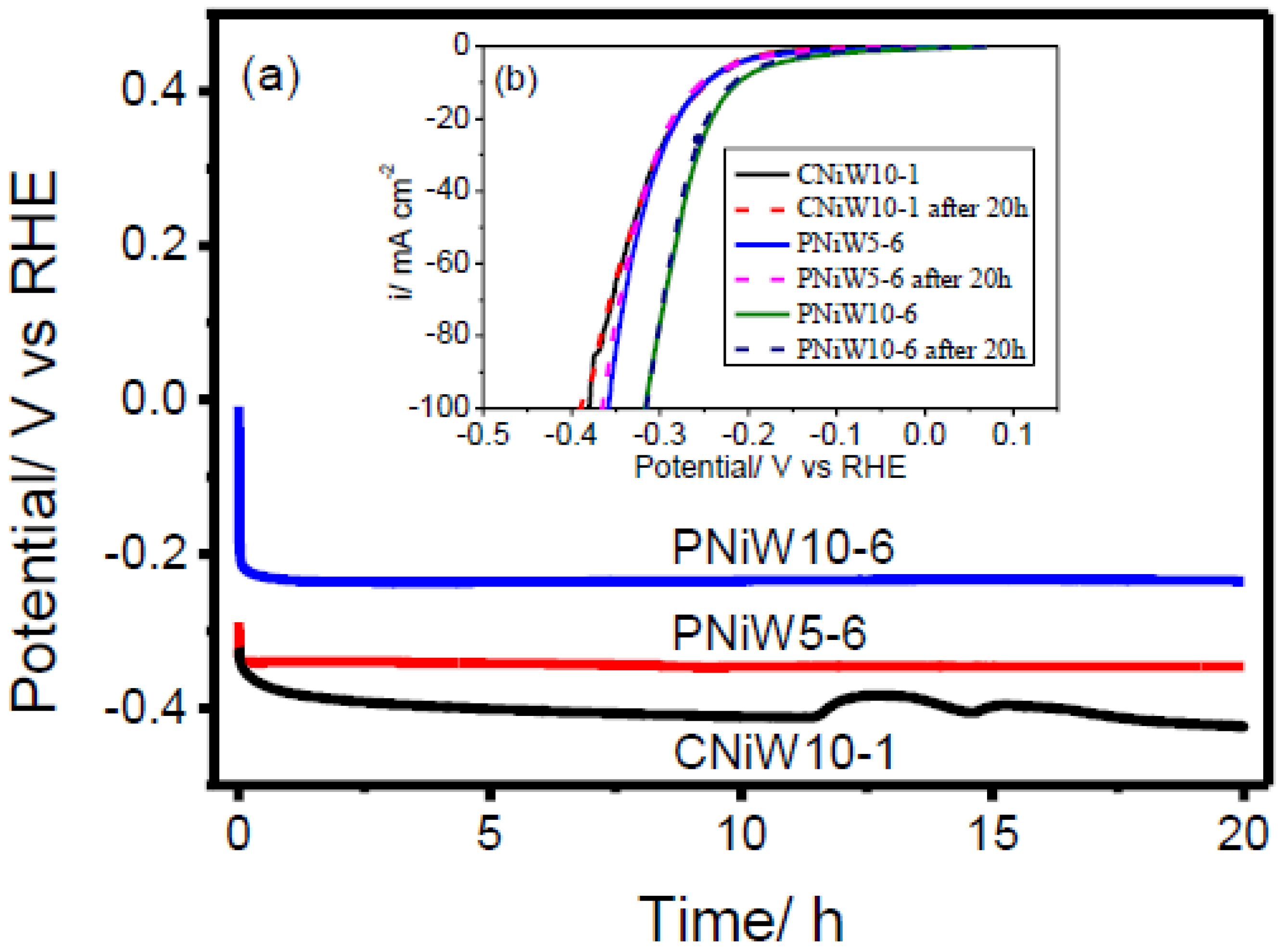
The stability of catalysts is one of the most important for their commercial applications. Chronopotentiometry (CP) technology was employed to estimate the electrocatalytic stability. Figure 11a plots the chronopotentiometric curves of CNiW10-1, PNiW5-6 and PNiW10-6 catalysts at 10 mA·cm−2 constant current for 20 h in 1.0 M NaOH solution. It can be seen that the overpotentials of all samples undergo a rapid attenuation in the initial short stage and then arrive at a platform. The LSV curves of CNiW10-1, PNiW5-6 and PNiW10-6, both before and after 20 h of CP test in 1M NaOH aqueous solution, are displayed in Figure 11b. The same HER overpotentials were preserved for CNiW10-1, PNiW5-6 and PNiW10-6, indicating their proven long-term stability. The crack CNiW10-1 catalyst experienced disturbance after 12 h, likely due to the release of internal stress in the as-deposited Ni-W alloy. The stable HER overpotentials of CNiW10-1, PNiW5-6 and PNiW10-6 are 408 mV, 344 mV and 235 mV at 10 mA cm−2, respectively.
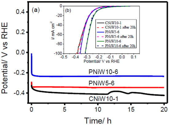
Figure 11.
(a) Chronopotentiometry recorded on the CNiW10-1, PNiW5-6 and PNiW10-6 electrodes in 1.0 M NaOH solution at 10 mA cm−2 for 20 h. (b) Linear sweep voltammetry (LSV) curves recorded on the CNiW10-1, PNiW5-6 and PNiW10-6 in 1.0 M NaOH solution at a scan rate of 10 mV s−1 after the chronopotentiometry (CP) test.
4. Conclusions
In summary, porous Ni-W catalysts were successfully fabricated via the DHBT method. The surface morphology of Ni-W alloys mainly depends on the applied current density and can be finely adjusted by the concentration of sodium tungstate. The results of electrochemical tests showed that the optimized coating is the PNiW10-6 catalyst formed in the bath, with a concentration of 100 g L−1 Na2WO4·2H2O at 0.6 A cm−2 for 5 min, which presents low overpotentials of 166 mV (η10), 213 mV (η20) and 269 mV (η50). XPS spectra of W4f and Ni 2P indicate that surface Ni and W are both in the oxidized state of Ni2+ and W6+ and in the atom state. CP data demonstrated that the electrocatalytic stability of porous Ni-W alloys, specifically PNiW10-6 and PNiW5-6, exceeds 20 h. Furthermore, under stable HER conditions in a 1.0 M NaOH solution, these alloys exhibit overpotentials of 235 mV and 344 mV at a current density of 10 mA cm−2, respectively. Such excellent electrocatalytic HER performance, which resulted from its high ECSA with 13-times the substrate Fe, high ECD of 0.741 mA cm−2 and low Rct of 9.30 Ω cm2, will allow researchers to apply this in the field of industrial hydrogen production.
Author Contributions
Conceptualization, C.S.; Methodology, L.L. (Linghao Li), Y.L. (Yangyang Liu), C.S. and W.T.; Software, Y.L. (Yufei Li); Formal analysis, Y.L. (Yufei Li); Investigation, L.L. (Linghao Li); Resources, W.L.; Data curation, Y.L. (Yangyang Liu); Writing—original draft, L.T. and Y.L. (Yangyang Liu); Writing—review & editing, L.L. (Linfeng Lu) and L.T.; Visualization, W.L. All authors have read and agreed to the published version of the manuscript.
Funding
This research was funded by the Provincial Natural Science Foundations of Hunan (2021JJ30184) and Doctoral Research Fund of Hunan Institute of Engineering (09001003-21017).
Institutional Review Board Statement
Not applicable.
Informed Consent Statement
Not applicable.
Data Availability Statement
Data is contained within the article.
Conflicts of Interest
Authors Yufei Li, Wenzhe Li, Linfeng Lu, Lu Tian were employed by PetroChina Southwest Oil and Gasfield Company. Author Weidong Tian was employed by Chengdu Davied Petroleum Technology Service Co., Ltd. The remaining authors declare that the research was conducted in the absence of any commercial or financial relationships that could be construed as a potential conflict of interest.
References
- Ren, Y.; Li, Z.; Deng, B.; Ye, C.; Zhang, L.; Wang, Y.; Wang, Y.; Li, T.; Liu, Q.; Cui, G.; et al. Superior hydrogen evolution electrocatalysis enabled by CoP nanowire array on graphite felt. Int. J. Hydrogen Energy 2022, 47, 3580–3586. [Google Scholar] [CrossRef]
- Zhang, L.C.; Chen, H.; Hou, G.R.; Zhang, L.Z.; Li, Q.L.; Wu, Y.K.; Xu, M.; Bao, S.J. Puzzle-inspired carbon dots coupled with cobalt phosphide for constructing a highly-effective overall water splitting interface. Chem. Commun. 2020, 56, 257–260. [Google Scholar] [CrossRef] [PubMed]
- Li, L.; Zhang, L.; Gou, L.; Wei, S.; Hou, X.; Wu, L. High-performance methanol electrolysis towards energy-saving hydrogen production: Using Cu2O-Cu decorated Ni2P nanoarray as bifunctional monolithic catalyst. Chem. Eng. J. 2023, 454, 140292. [Google Scholar] [CrossRef]
- Zhang, L.; Li, L.; Liang, J.; Fan, X.; He, X.; Chen, J.; Li, J.; Li, Z.; Cai, Z.; Sun, Z.; et al. Highly efficient and stable oxygen evolution from seawater enabled by a hierarchical NiMoSx microcolumn@ NiFe-layered double hydroxide nanosheet array. Inorg. Chem. Front. 2023, 10, 2766–2775. [Google Scholar] [CrossRef]
- Zhang, L.; Zhao, H.; Xu, S.; Liu, Q.; Li, T.; Luo, Y.; Gao, H.; Shi, X.; Asiri, A.; Sun, X. Recent Advances in 1D ElectrospunNanocatalysts for Electrochemical Water Splitting. Small Struct. 2022, 2, 2000048. [Google Scholar] [CrossRef]
- Jiang, H.; Cong, N.; Jiang, H.; Tian, M.; Xie, Z.; Fang, H.; Han, J.; Ren, Z.; Zhu, Y. Dynamic hydrogen bubble template electrodeposition of Ru on amorphous Co support for electrochemical hydrogen evolution. Int. J. Hydrogen Energy 2023, 48, 21599–21609. [Google Scholar] [CrossRef]
- Zhao, G.; Rui, K.; Dou, S.X.; Sun, W. Heterostructures for electrochemical hydrogen evolution reaction: A review. Adv. Funct. Mater. 2018, 28, 1803291. [Google Scholar] [CrossRef]
- Vernickaite, E.; Tsyntsaru, N.; Sobczak, K.; Cesiulis, H. Electrodeposited tungsten-rich Ni-W, Co-W and Fe-W cathodes for efficient hydrogen evolution in alkaline medium. Electrochim. Acta 2019, 318, 597–606. [Google Scholar] [CrossRef]
- Yu, X.; Yang, J.; Sui, Z.; Wang, M. Effects of ultrasonic field on structure evolution of Ni film electrodeposited by bubble template method for hydrogen evolution electrocatalysis. J. Solid State Electrochem. 2021, 25, 2201–2212. [Google Scholar] [CrossRef]
- González-Buch, C.; Herraiz-Cardona, I.; Ortega, E.; García-Antón, J.; Pérez-Herranz, V. Synthesis and characterization of macroporous Ni, Co and Ni-Co electrocatalytic deposits for hydrogen evolution reaction in alkaline media. Int. J. Hydrogen Energy 2013, 38, 10157–10169. [Google Scholar] [CrossRef]
- Wang, J.; Shao, H.; Ren, S.; Hu, A.; Li, M. Fabrication of porous Ni-Co catalytic electrode with high performance in hydrogen evolution reaction. Appl. Surf. Sci. 2021, 539, 148045. [Google Scholar] [CrossRef]
- Barati Darband, G.; Aliofkhazraei, M.; Sabour Rouhaghdam, A.; Kiani, M.A. Three-dimensional Ni-Co alloy hierarchical nanostructure as efficient non-noble-metal electrocatalyst for hydrogen evolution reaction. Appl. Surf. Sci. 2019, 465, 846–862. [Google Scholar] [CrossRef]
- Reda, Y.; Abdel-Karim, R.; Zohdy, K.M.; El-Raghy, S. Electrochemical behavior of Ni-Cu foams fabricated by dynamic hydrogen bubble template electrodeposition used for energy applications. Ain Shams Eng. J. 2022, 13, 101532. [Google Scholar] [CrossRef]
- Han, Q.; Cui, S.; Pu, N.; Chen, J.; Liu, K.; Wei, X. A study on pulse plating amorphous Ni-Mo alloy coating used as HER cathode in alkaline medium. Int. J. Hydrogen Energy 2010, 35, 5194–5201. [Google Scholar] [CrossRef]
- Wang, M.; Wang, Z.; Yu, X.; Guo, Z. Facile one-step electrodeposition preparation of porous Ni-Mo film as electrocatalyst for hydrogen evolution reaction. Int. J. Hydrogen Energy 2015, 40, 2173–2181. [Google Scholar] [CrossRef]
- Raveendran, M.; Neethu, A.; Chitharanjan, H. Development of Ni-W alloy coatings and their electrocatalytic activity for water splitting reaction. Phys. B Condens. Matter 2020, 597, 412359. [Google Scholar] [CrossRef]
- Jameei Rad, P.; Aliofkhazraei, M.; Barati Darband, G. Ni-W nanostructure well-marked by Ni selective etching for enhanced hydrogen evolution reaction. Int. J. Hydrogen Energy 2019, 44, 880–894. [Google Scholar] [CrossRef]
- Hong, S.H.; Ahn, S.H.; Choi, J.; Kim, J.Y.; Kim, H.Y.; Kim, H.J.; Jang, J.H.; Kim, H.; Kim, S.K. High-activity electrodeposited Ni-W catalysts for hydrogen evolution in alkaline water electrolysis. Appl. Surf. Sci. 2015, 349, 629–635. [Google Scholar] [CrossRef]
- Tang, J.; Niu, J.; Yang, C.; Rajendran, S.; Lei, Y.; Sawangphruk, M.; Zhang, X.; Qin, J. Twin boundaries boost the hydrogen evolution reaction on the solid solution of nickel and tungsten. Fuel 2022, 330, 125510. [Google Scholar] [CrossRef]
- Gao, D.; Guo, J.; Cui, X.; Yang, L.; Yang, Y.; He, H.; Xiao, P.; Zhang, Y. Three-Dimensional Dendritic Structures of Ni-Co-Mo as Efficient Electrocatalysts for the Hydrogen Evolution Reaction. ACS Appl. Mater. Interfaces 2017, 9, 22420–22431. [Google Scholar] [CrossRef]
- Vijayakumar, J.; Mohan, S.; Anand Kumar, S.; Suseendiran, S.R.; Pavithra, S. Electrodeposition of Ni-Co-Sn alloy from choline chloride-based deep eutectic solvent and characterization as cathode for hydrogen evolution in alkaline solution. Int. J. Hydrogen Energy 2013, 38, 10208–10214. [Google Scholar] [CrossRef]
- Lotfi, N.; Barati Darband, G.H. Energy-Saving Electrochemical Hydrogen Production on Dynamic Hydrogen Bubble-Template Electrodeposited Ni-Cu-Mn Nano-Micro Dendrite. J. Electrochem. Soc. 2022, 169, 096508. [Google Scholar] [CrossRef]
- Lu, S.S.; Shang, X.; Zhang, L.M.; Dong, B.; Gao, W.K.; Dai, F.N.; Liu, B.; Chai, Y.M.; Liu, C.G. Heterostructured binary Ni-W sulfides nanosheets as pH-universal electrocatalyst for hydrogen evolution. Appl. Surf. Sci. 2018, 445, 445–453. [Google Scholar] [CrossRef]
- Machado Oliveira, J.A.; Filgueirade Almeida, A.; Nascimento Campos, A.R.; Prasad, S.; Nicacio Alves, J.J.; Costa de Santana, R.A. Effect of current density, temperature and bath pH on properties of Ni-W-Co alloys obtained by electrodeposition. J. Alloys Compd. 2021, 853, 157104. [Google Scholar] [CrossRef]
- Allahyarzadeh, M.H.; Aliofkhazraei, M.; Rezvanian, A.R.; Torabinejad, V.; Sabour Rouhaghdam, A.R. Ni-W electrodeposited coatings: Characterization, properties and applications. Surf. Coat. Technol. 2016, 307, 978–1010. [Google Scholar] [CrossRef]
- Bahari Mollamahale, Y.; Jafari, N.; Hosseini, D. Electrodeposited Ni-W nanoparticles: Enhanced catalytic activity toward hydrogen evolution reaction in acidic media. Mater. Lett. 2018, 213, 15–18. [Google Scholar] [CrossRef]
- Zhang, Y.; Bilan, H.K.; Podlaha, E. Enhancing the hydrogen evolution reaction with Ni-W-TiO2 composites. Electrochem. Commun. 2018, 96, 108–112. [Google Scholar] [CrossRef]
- Su, C.; Sa, Z.; Liu, Y.; Zhao, L.; Wu, F.; Bai, W. Excellent Properties of Ni-15 wt.% W Alloy Electrodeposited from a Low-Temperature Pyrophosphate System. Coatings 2021, 11, 1262. [Google Scholar] [CrossRef]
- Juškėnas, R.; Valsiūnas, I.; Pakštas, V.; Selskis, A.; Jasulaitienė, V.; Karpavičienė, V.; Kapočius, V. XRD, XPS and AFM studies of the unknown phase formed on the surface during electrodeposition of Ni–W alloy. Appl. Surf. Sci. 2006, 253, 1435–1442. [Google Scholar] [CrossRef]
- Chianpairot, A.; Lothongkum, G.; Schuh, C.A.; Boonyongmaneerat, Y. Corrosion of nanocrystalline Ni-W alloys in alkaline and acidic 3.5wt.% NaCl solutions. Corros. Sci. 2011, 53, 1066–1071. [Google Scholar] [CrossRef]
- Rosalbino, F.; Delsante, S.; Borzone, G.; Angelini, E.M.M.A. Correlation of microstructure and catalytic activity of crystalline Ni–Co–Y alloy electrode for the hydrogen evolution reaction in alkaline solution. J. Alloys Compd. 2007, 429, 270–275. [Google Scholar] [CrossRef]
- McCrory, C.C.L.; Jung, S.; Peters, J.C.; Jaramillo, T.F. Benchmarking Heterogeneous Electrocatalysts for the Oxygen Evolution Reaction. J. Am. Chem. Soc. 2013, 135, 16977–16987. [Google Scholar] [CrossRef] [PubMed]


Disclaimer/Publisher’s Note: The statements, opinions and data contained in all publications are solely those of the individual author(s) and contributor(s) and not of MDPI and/or the editor(s). MDPI and/or the editor(s) disclaim responsibility for any injury to people or property resulting from any ideas, methods, instructions or products referred to in the content. |
© 2024 by the authors. Licensee MDPI, Basel, Switzerland. This article is an open access article distributed under the terms and conditions of the Creative Commons Attribution (CC BY) license (https://creativecommons.org/licenses/by/4.0/).