Article

Post-Wear Surface Morphology Assessment of Selective Laser Melting (SLM) AlSi10Mg Specimens after Heat Exposure to Different Gas Flames

1
Mechanical and Industrial Engineering Department, College of Engineering, Imam Mohammad Ibn Saud Islamic University, Riyadh 11432, Saudi Arabia
2
Mechanical Engineering Department, NED University of Engineering & Technology, Karachi 75270, Pakistan
3
Metallurgical Engineering Department, NED University of Engineering & Technology, Karachi 75270, Pakistan
4
School of Mechanical Engineering, Northwestern Polytechnical University, Xi’an 710072, China
*
Author to whom correspondence should be addressed.
Coatings 2024, 14(3), 252; https://doi.org/10.3390/coatings14030252
Submission received: 14 December 2023 / Revised: 25 January 2024 / Accepted: 14 February 2024 / Published: 20 February 2024

Abstract

:
The wear surface morphology of AlSi10Mg specimens, originally manufactured using selective laser melting (SLM), has been analyzed in the context of exposure to heat from gas flames. The first stage of the experimental work included the performance of surface heat-exposure on SLM-prepared specimens through oxyacetylene gas welding. Gas welding was utilized with three different flames, namely; reducing, neutral, and oxidizing on the as-built specimens of SLM. The post-surface-treated specimens were subjected to pin-on-disk wear testing against fixed parameters. After the performance of wear testing at two different radii, the mass loss of each of the four types of specimens was calculated including the three specimens exposed to heat along with the as-built specimens. The results showed that the maximum amount of mass losses at 24 mm and 30 mm radii belongs to the neutral flame specimens and the least was for the as-built condition specimens. Upon analysis, the heat-exposure specimens through all three types of gas flames resulted in an increase in the amount of mass in contrast to the as-built specimens. Moreover, the morphologies of the developed wear tracks at surfaces were examined using the scanning electron microscope (SEM) for the understating of the mechanism.

1. Introduction

The term additive manufacturing (AM) is most commonly renowned with the word 3D printing with the help of layer-by-layer deposition of material in the creation of prototypes and complex geometries along with controlling waste over substantive manufacturing and customized production [1]. This technology has equal applications for all types of industries but especially demanding for aerospace, medical, electrical vehicles, and critical jigs and fixtures production. However, the research studies are being conducted extensively in the direction of materials and process optimization. Overall, additive manufacturing has shown great potential for transforming the manufacturing industry with ongoing research focusing on further improving the technology and expanding its applications [2].
Aluminum alloys have found a wide range of applications considering and fulfilling the lightweight criterion for the automotive, aerospace, machine construction, and electronic appliances as well as for the domestic utensils [3]. Aluminum alloys such as Al-Si, Al-Mg-Si, Al-Cu, and Al-Zn have been identified as resourceful alloys for multiple applications along with the capability of displaying higher mechanical behavior upon the generation of fine precipitates [4] in the matrix. Currently, among the additive manufacturing techniques, Laser Powder Bed Fusion (LPBF) is one of the most preferred additive techniques to produce metallic components with having integration with a high-power laser source for melting, and become commercially known as Selective Laser Melting (SLM). The SLM is also expected to revolutionize the manufacturing industry by providing ease in the cycle of design and flexibility in the time and material utilization by also considering the geometrical complexity, defect-free, and fully dense parts of high quality [5,6]. AlSi10Mg is one of the most frequently used aluminum alloys that is integrated with SLM and exhibits good mechanical behavior in as-built conditions [7]. The authors are particularly concerned with assessing the wear surface morphology of SLM AlSi10Mg alloy with surface heat exposure from gas flames.
Many additively prepared aluminum alloys including the AlSi10Mg have the potential to be used for static and dynamic performances in the automobile and aerospace sector like in casted conditions. However, sometimes the elevation of temperature approaches more than 150 °C while operating for a long duration. This can potentially reduce the mechanical behavior of the developed component causing the coarsening and dissolution of the developed precipitates even more pronounced in the cases of heat-treatable aluminum alloys [8]. This will also reduce the useful and service life of the potentially sliding components. However, a good tribological assessment in terms of the wearing of these components can help find the remaining life and associated reliability. There are only two possible cases to increase the life of the components; one is to reduce the friction by providing good lubrication while the other is to prior assessment and proactive prediction of wear behavior according to tentative working conditions where it is fitted [9].
To connect with one of the above-discussed situations where the temperature is also an associated case from any utilized or surrounding commonly fabrication techniques such as electric arc and gas welding. Surface heat exposure (melting) is a developed process that locally affects, melts, and solidifies a thin layer from the material’s surface. Possibly this study can be treated as a simulator to find the changes in surface properties and functionalities. Therefore, high energy sources are considered such as electric arc, gas flames, laser, electron, and plasma beam sources for instantaneous melting and further rapid solidification resulting in changes in composition, microstructure, and ultimately the consequence on the mechanical behavior. The famous post-surface remelting techniques for the above objective are laser surface remelting (LSM), electron beam surface remelting, and plasma surface remelting [10,11].
From the available different techniques, LSM is frequently used for wide applications for surface remelting that utilize a high-power laser beam for melting. The procedure involves localized remelting of the surface, which ultimately changes the microstructure and mechanical behavior in contrast to the base material properties. However, the exact performance is most likely dependent on operating parameters like laser power, exposure time, and spot size [12]. Furthermore, surface remelting through an electron beam is also a high-tech operation and also demonstrated an appreciated potential to remelt the surface, which tailors the surface properties of metallic materials. The applications of remelting even prior electroplated with Ni and Ni-WC, and subsequently remelted the surface through electron beam to withstand extreme temperature and high strength alloys such as Ti-6Al-4V (TC4) [13] and titanium grade 2 (TA2) [14] is also reported to improve the further surface hardness and wear resistance. Several studies have also disclosed the consideration of plasma beam remelting as a good alternative source [15] with key characteristics and advantages including superior metallurgical bond formation, ease of operation, high efficiency of heating, and minimal dimensional changes along with localized hardening [16].
The process of providing surface heat-exposure can also be carried out through oxyacetylene gas welding operations using different types of flames, such as neutral, carburizing, and oxidizing flames, to analyze the results on surfaces. This operation is relatively very cheap in comparison with the above-discussed remelting cases and opens a window to execute post-surface heat exposure on the low-temperature lightweight alloys prepared through additive manufacturing. The importance and the industrial application of the presented work is to integrate and explore the detrimental effects created on the aluminum alloys against heat exposure, which were previously cold worked, heat treated, or fabricated from specialized processes for higher mechanical behavior. The exposure to heat may be experienced as a result of exceeding operational factors including leakage of hot gases, high-temperature generation near engine components; maintenance procedures nearby section joining-repair causing repeated heat cycle; or accidental fire. In a similar context, the cold-worked hole fasteners of aluminum alloy that were provided with the benefit of compressive residual stresses to delay the crack initiation and growth; experienced higher fatigue growth rates when exposed to a temperature of 150 °C [17,18]. In addition, Jabra et al. [19] explored the effect of thermal exposure on different aluminum alloy plates in different conditions, and reported a reduction in the strength and hardness. However, Ceschini et al. [20] planned to study the effect of thermal exposure on A356 aluminum alloy in the casted form to report their mechanical properties; the ultimate tensile strength and yield strength are reported to decrease by 32% and 40%, respectively, after thermal exposure at 210 °C for 41 h. This was attributed to the coarsening of precipitates after the exposure to heat. Therefore, exposure to heat is also critical to assess the high cost and performance processes such as SLM where higher mechanical behavior is expected by the user, and even become more severe for heat treatable sensitive alloys such as AlSi10Mg.
As far as the AlSi10Mg is concerned, a typically heat-treatable alloy with good casting properties along with widely investigated AM alloy with SLM process. Moreover, several studies have reported extremely fine microstructure that promotes better mechanical behavior in the as-built condition in contrast to solution and T6 heat treatment conditions [21,22]. The coarsening of the microstructure and the disruption of the Si-network while solution treatment induces ductility and less resistance to wear, and prolonged holding for T6 treatment causes porosity growing is the probable contribution in the reduction of mechanical behavior comparable to as-built condition. Despite the higher number of studies reporting the aforementioned behavior considering mechanical properties, process parameter optimization, and morphological studies, only a few research studies available in the literature report the wear behavior of AlSi10Mg alloy. Tonolini et al. [23] presented a comprehensive wear behavior comparison of AlSi10Mg considering the as-built, and T6 heat treatment along with the gravity casting of similar alloy. The as-built AM specimens exhibit the lowest wear rate, whereas the heat-treatable specimens depicted the worst wear behavior in contrast to other cases. Another work by Park et al. [24] highlighted the comparison of mass loss against the as-built, direct aging, and T6 treatment specimens reported a decrease in the hardness value at the T6 treatment condition but a slight improvement in the mass loss in comparison to the as-built specimens.
Despite the current trend in the utilization of the above high-cost heat sources to re-melt the surface and heat-treatment procedures, the exposure of gas welding source on the surface of AlSi10Mg alloy behavior is not available and the tribological behavior findings are overall unclear. This executed work is focused precisely on the sliding wear behavior considering the heat exposure through a gas welding heat source. Moreover, the change in the surface properties based on heat treatments such as solution heat treatment and age hardening have been a point of focus for quite some time. However, the study on the change in surface behavior through heat-exposure considering gas welding with various flames is a topic less discovered. This research gap was identified and the major aim of this paper is to study the possibilities of heat exposure on AlSi10Mg alloy through gas welding by deploying various flames. Nevertheless, high stresses can be created at any time in severe operating and working conditions and leave the specimens in the previously mentioned more ductile and less wear-resistant state. Eventually, the pin-on-disc test was selected to execute the wear testing and the SEM images to understand the wear track mechanisms of the as-built and heat-exposure surfaces from gas flames.

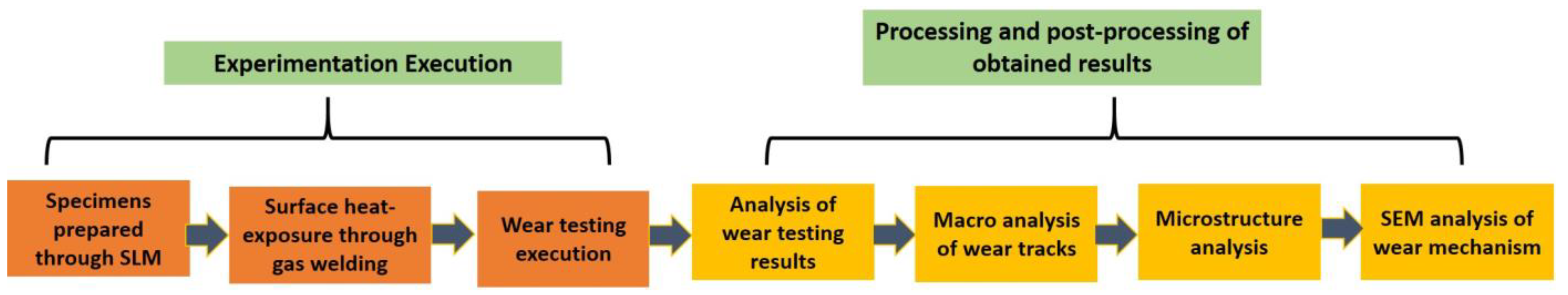
2. Experimental and Methodology

The roadmap to execute the overall work is given in Figure 1, which further divides the work into seven major tasks, including the experimentation execution for specimen preparation and conducting the wear testing. However, the details of SLM specimens, surface heat-exposure through oxyacetylene gas flames, and further performance of wear testing are presented under the domain of this heading; while the processing and post-processing of the obtained wear testing results including the macro analysis of wear tracks, microstructure/elemental mapping, and SEM analysis of wear mechanism are presented and described under the next section as illustrated in Figure 1.

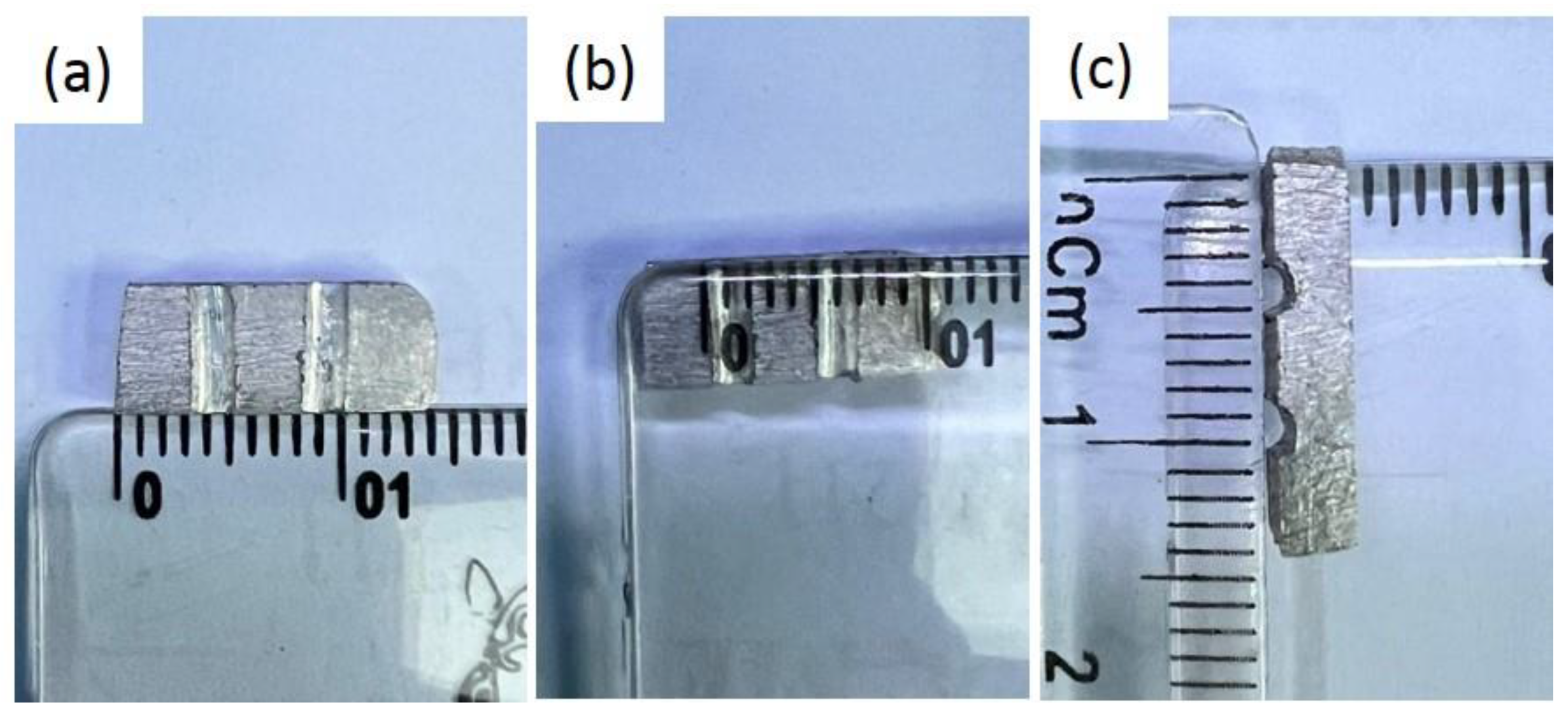
2.1. Fabrication of AlSi10Mg Specimens through SLM

The SLM 280HL (SLM Solutions, Lübeck, Germany) facility is used to prepare the specimens. The gas-atomized powder of AlSi10Mg was used for the experimentation, the particle sizes ranged from 15 µm to 58 µm [25]. Moreover, the selection of parameters is important for the SLM process in achieving a defect-free structure, good mechanical properties, and maximum relative density. Several researchers have reported different parameters for the printing of specimens to optimize the process. For this work, the optimal process parameters are used from the author’s preliminary studies on different targeted themes such as explicit mechanical behavior and heat treatment behavior [26,27] of SLM specimens. These considered parameters are given in Table 1. The 2.5 mm walled thickness SLM specimens were fabricated as similarly produced in the previous study [26] based on parameters given in Table 1. The schematic illustration of the fabrication of specimens is provided in Figure 2.

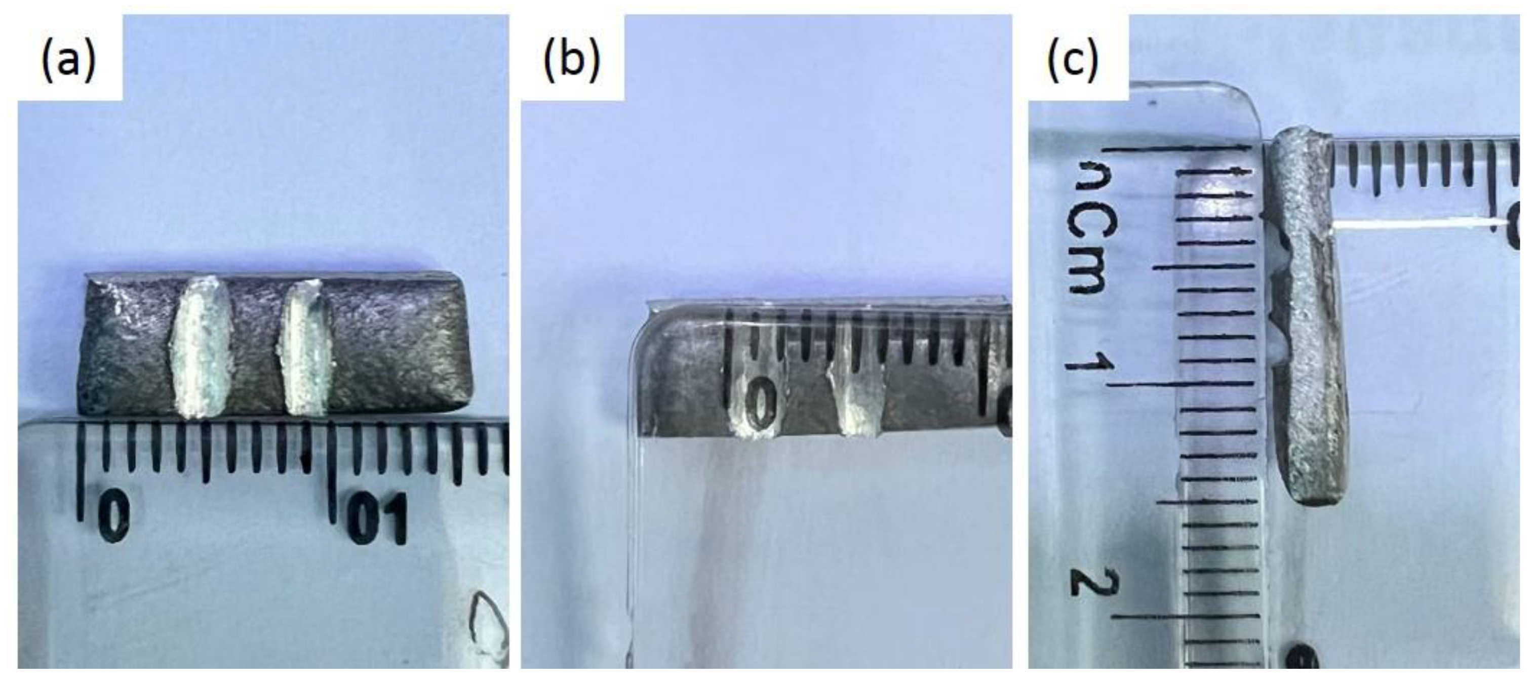
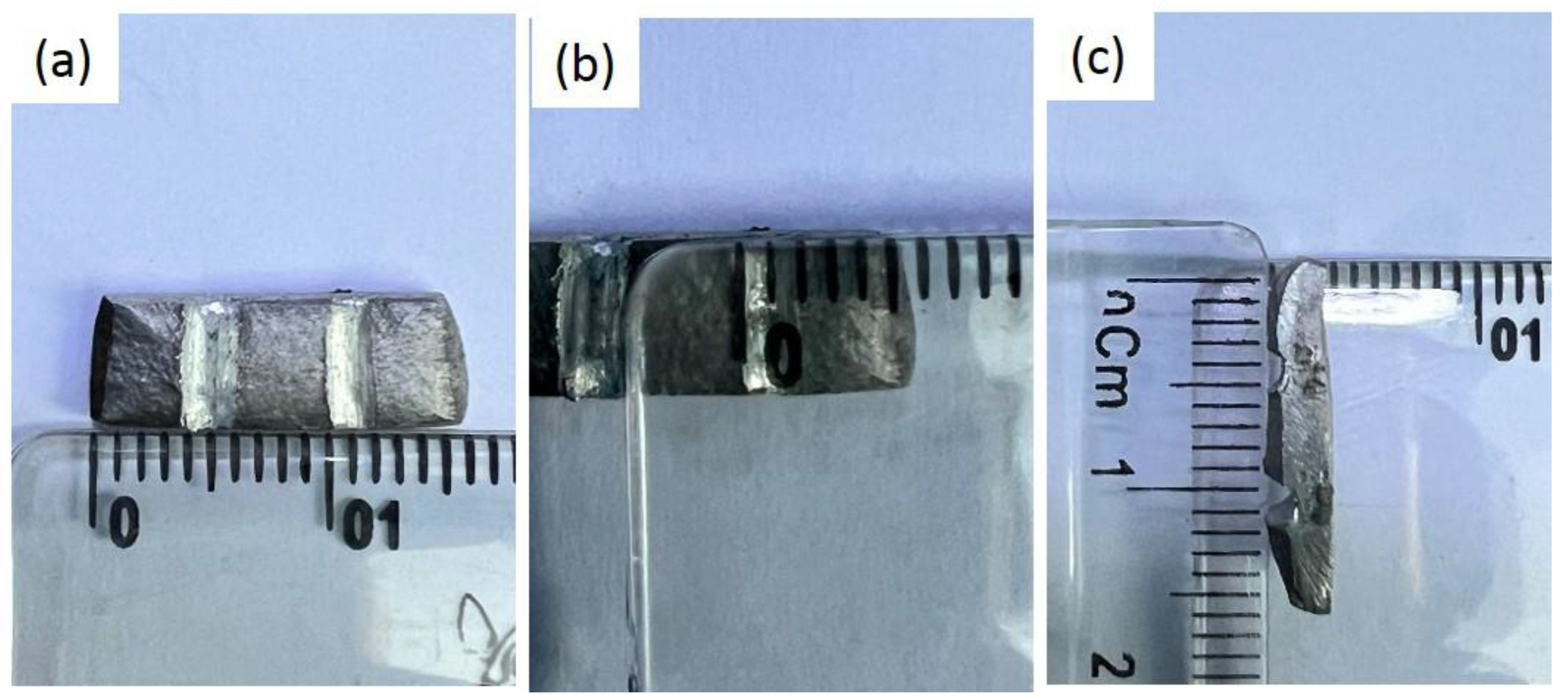
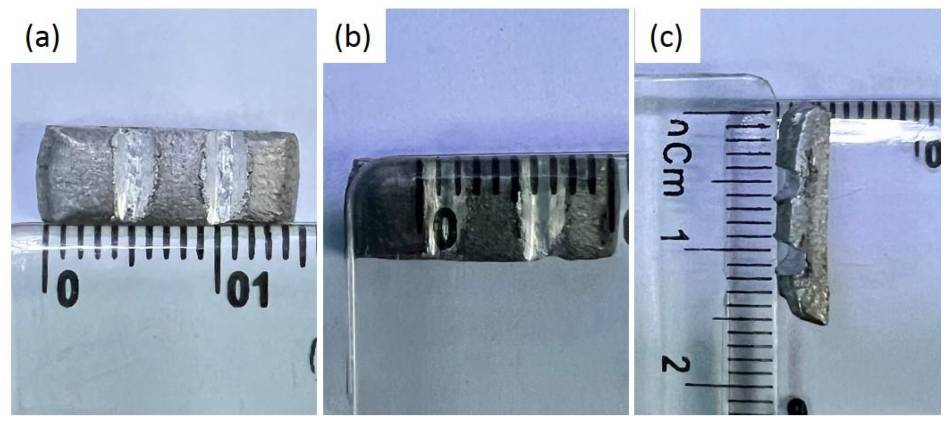
2.2. Execution of Surface Heat Exposure from Gas Flames

The prime purpose of the presented research work is to provide heat exposure to the surface of SLM-prepared specimens through gas flames from welding torch and their further assessment of behavior through wear testing. Three principal types of flames can be used from gas welding torch, neutral, oxidizing, and carburizing, each with its unique characteristics and applications towards joining. In gas welding, the most common type of flame is the neutral flame, which is created by combining equal amounts of oxygen and acetylene gas, and its chemical composition is balanced, resulting in a clean and stable flame. The neutral flame has a light blue inner cone that is bordered by a darker blue outer cone and is appropriate for welding most common metals.
The oxidizing flame is created by increasing the flow of oxygen while decreasing the flow of acetylene. This flame has a higher oxygen concentration, resulting in a hotter and more intense flame. It has a short inner cone and a long, pointed outer cone. The carburizing flame is created by raising the acetylene flow while decreasing the oxygen flow. This flame contains more acetylene, resulting in a reducing environment that can allow carbon to be absorbed into the weld or surface. It has a long, bright inner cone and a smaller, less visible outer cone. The parameters involved in executing the work are to open the oxygen and acetylene cylinders at 4 Psi and 5 Psi pressures, respectively. The physical setup of the gas welding is equipped with the adjusting knobs of gas mixtures at the torch. After the flame was created, the surface was heated in a single pass. After exposure, the specimen was cooled in air before being subjected to wear testing at two different radii.

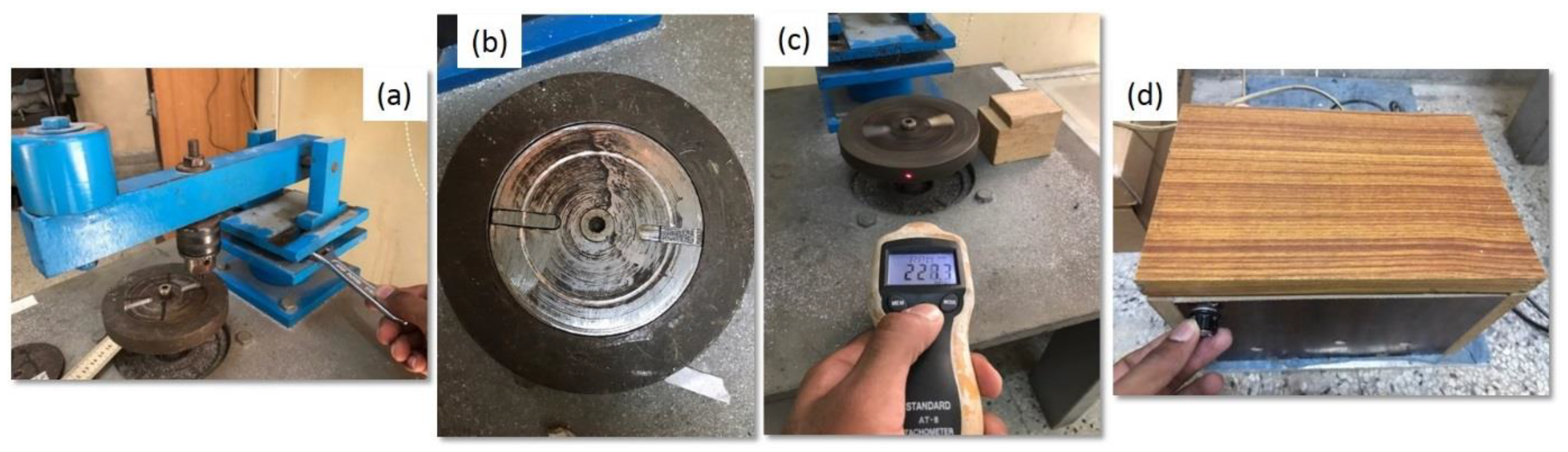
2.3. Wear Testing Execution

As highlighted in Figure 1, wear testing execution is the prime and major objective of this study, to find out which flame type experiences the most and least mass loss after the execution of the test. Both the as-built specimen and each of the surface-treated specimens underwent wear testing. Therefore, in addition to the as-built specimen, wear testing was carried out sequentially on all three distinctly flame-surface melted specimens. ASTM G99-05 standard [28] test method is followed to execute the wear testing with a pin on the disc apparatus. This standard covers a laboratory procedure for the determination of wear mass during sliding using a pin-on-disc apparatus. To execute this test based on ASTM G99-05, a pin is required which is positioned perpendicular usually a flat circular disc. However, either the pin specimen or disc specimen may revolve or rotate causing the formation of circular tracks. In this study, a stationary pin is used against a flat fixture plate, which held the SLM-prepared specimens.
The further emphasis and guidelines from ASTM G99-05 involve; the equipment requires a motor drive to rotate the disc at the specified velocity, a revolution counter (such as a tachometer) to measure the speed, a holder that holds the pin in place and apply a test force proportional to the mass of the weight, and an electronic mass balance having a sensitivity of 0.1 mg to measure the mass loss. From this wear testing system, load, speed, and sliding distance are the possible test parameters from ASTM G99-05 while temperature and atmosphere may also be accounted for. For this work, tungsten carbide is utilized as a superior static pin (stationary), and the mass loss is measured from a revolving special disk-fixture carrying the SLM specimens.
Based on the above information from ASTM G99-05, the time and radius of the disc-fixture to achieve the desired sliding distances of testing and rotating speed (Revolution per Minute (RPM)) are the constant controllable factors in the study to execute the wear testing and further proceed to mass loss measurements. First, the disk fixture was set to rotate continuously for 90 s while being subjected to wear testing, and the duration was monitored using a stopwatch. Secondly, once the specimen is securely placed into the fixture slot, the speed controller is activated, and the rotating speed is set using the built-in regulator with the machine to a range of 227–228 PRM. Lastly, the radius between the tip of the pin and the center of the rotating disk-fixture was calculated using the meter ruler. The experiment included two sets of values, the first with a radius of 24 mm and the second with a radius of 30 mm.
The in-house fabricated wear-testing device as shown in Figure 3 was used for testing that had a pin holder attached to the loading lever, formally called a pin-on-disc machine. The sequence of wear testing machine adjustment is pictorially illustrated in Figure 3. As highlighted in Figure 3a, a fixture is placed onto the rotating disc that has a slot to fix the under-observation specimen and is tightened using the Allen key. The radius of the wear testing machine needed to adjust at the 24 mm and 30 mm radii, which is possible due to the sliding mechanism provision provided in the machine. As highlighted in Figure 3a, the wear testing machine used for this work is shown along with the rotating disc and a dead load of 1 kg at the edge of the lever. The fixture having two slots placed onto the disc holder is separately shown in Figure 3b. One slot of the fixture was used to place the SLM fabricated AlSi10Mg specimen while the other is a dummy, filled with the steel piece for balance. A tachometer was used to monitor and ensure the speed of the disc as highlighted in Figure 3c, and a controller box was in Figure 3d. The observed values for the mass losses while performing wear testing, one at 24 mm and the other at 30 mm radius are provided in Table 2. Before and after the execution of testing, the electronic mass-balance device with a sensitivity of three digits was used to measure the mass loss. Moreover, the microstructure analysis is also executed using the optical microscope considering the standardized practices of grinding and polishing, which were etched by Keller’s reagent to reveal the structure. In addition, the wear surface analysis is executed to ensure the type of wear and characterized through SEM (Zeiss, Oberkochen, Germany), and the elemental mapping analysis of the cross-sections done on energy-dispersive X-ray spectroscopy (EDX) equipped with SEM.

3. Results and Discussion

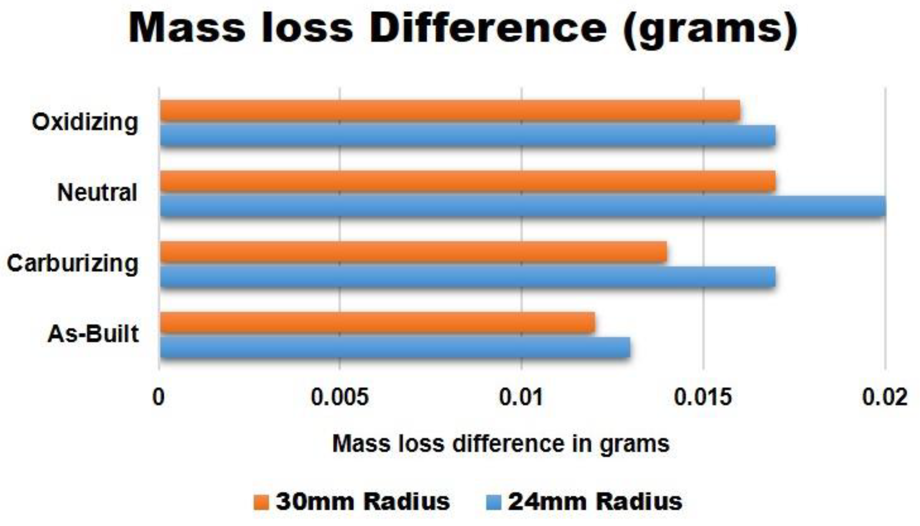
3.1. Mass Loss Analysis after Wear Testing

The developed alloy performance of AlSi10Mg through SLM can be controlled and analyzed from two perspectives. The first is the material’s developed behavior against the additive manufacturing process to analyze the as-built properties including tensile strength, surface roughness, relative density, porosities, and microstructural features. However, this understanding is already in consideration and presented gradually [29,30] in multiple studies. The other side is the execution by changing the operating conditions and parameters such as applied normal load, sliding distance, lubricating condition, or the testing in harsh conditions integrating with temperature and acidic environment against any specific post-heat heat exposure and heat-treatment to assess the positive and negative impact. The subsequent sections featured the effect of oxyacetylene gas flame exposure and its influence on the surface of SLM-prepared specimens in terms of mass losses.
The results of the pin-on-disc wear testing in the as-built and after the surface exposure from gas flames are presented in Table 2. For assessing the results of the wear testing, the difference in the masses of the specimens was noted before and after the experimentation. Initially, the masses were measured using an electronic weight balance and afterward, the masses were again measured after the post-surface exposure of wear testing. The experimentation was executed at two different radii, i.e., at 24 mm and 30 mm. The subsequent mass losses before and after the testing, mass differences, and the percentage of mass losses are highlighted in Table 2.
Table 2 shows that the surface gas flame-treated specimens maintained a higher mass loss for every type of flame for both the considered radii than the as-built condition specimen of SLM. For the execution at a 24 mm radius, the mass loss difference is 0.017, 0.020, and 0.016 g for carburizing, neutral, and oxidizing flames in contrast to the value of 0.013 g for as-built conditions. Besides the 30 mm radius, the mass loss differences are 0.014, 0.017, and 0.016 g for carburizing, neutral, and oxidizing flames respectively when compared to the value of as-built, which is just 0.012 g. The mass loss values for the heat exposure specimens at the three flames conferred almost the same values at 24 mm except for the neutral flame, while these values are progressively higher than the obtained value of an as-built specimen. Anyhow, the variation in the mass loss at a 30 mm radius is more evident within the three types of flames. The lowest mass difference is captured for the carburizing flame, and the ultimate for the neutral flame, but a similar progressive increment in the mass loss is allied with the 24 mm radius corresponding to the as-built specimen.
Figure 4 plots the graphical comparison in terms of the mass loss difference for the carburizing, neutral, and oxidizing flames at 24 mm and 30 mm of radii used in the wear testing with the as-built obtained values. However, purely to plot the percentage of mass loss is not fruitful as the initial mass of the specimens is not constant or the same. It is observed that the smallest block of mass loss belongs to the as-built condition with the values of 0.013 and 0.012 g at 24 mm and 30 mm radii, respectively, as well as the percentage of mass loss, which is graphically shown at the bottom of Figure 4. However, the other percentage of mass losses after the heat exposure from different flames is given in Table 2 in comparison with the as-built SLM. The exact mass loss block for carburizing flames is plotted just above the as-built block, which is the increasing one in comparison to the as-built condition but the lowest mass loss percentage in contrast to other gas welding flames. Nevertheless, the oxidizing flame performed better in terms of percentage and difference at both the radii of 24 mm and 30 mm when compared to the percentage and values of neutral flame. Concisely, it is evident that the maximum percentages of mass losses occurred when the specimens were provided with heat exposure through the oxyacetylene gas flames subject to the same testing condition.
The surface developed through the SLM process in the as-built condition is more resistant to the penetration of asperities against the wearing as concluded from the results depicted in Table 2 and Figure 4. The primary cause for this behavior arises from the strengthening provided by the structure developed in the as-built condition of the SLM process, while the higher mass loss behavior is connected and explained in the subsequent Section 3.3 of Microstructure [4]. However, it is also noticed that the grain size plays a critical role against the sliding action while performing the wear testing [21]. The oxyacetylene gas flames reduce the grain size prior developed from the process in the as-built condition at the localized surface. As a result, when the normal load applied to the surface it ultimately transmitted directly from the weak top surface and offered low resistance to wear. The other argument for the higher mass loss percentages is the curvature developed at the melted surface, as shown in the next Section 3.2, is eventually responsible for supporting the normal applied load. This causes easy exhibitance of the counterface pin asperities to the weak and soft aluminum melted surface having large grains and curvature, which offers low resistance and increased mass loss percentages in contrast to the as-built SLM specimen.

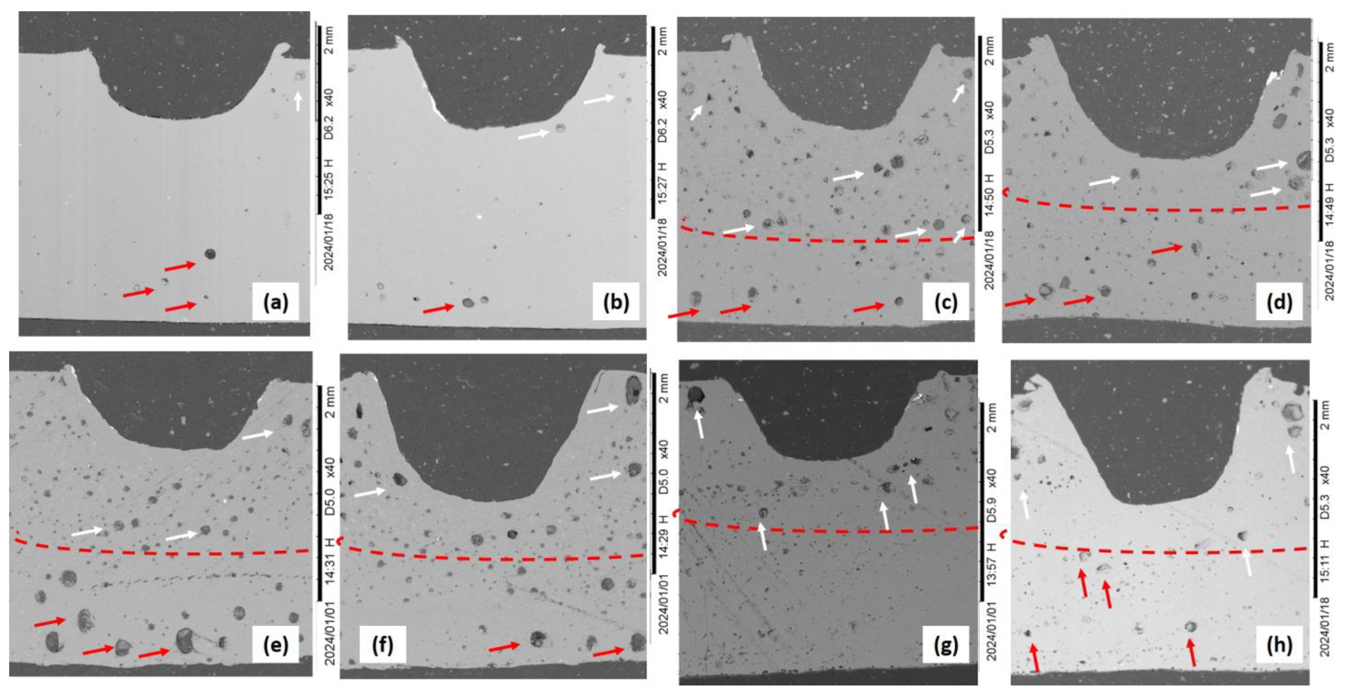
3.2. Macro Analysis of Wear-Track Images and Cross-Sections

Figure 5, Figure 6, Figure 7 and Figure 8 show the macro images of the worn surfaces i.e., the wear tracks of the as-built, carburize, neutral, and oxidizing flames generated from the oxyacetylene gas welding respectively. According to the captured macro images, the as-built and the heat exposure specimens revealed sharp grooves but of different morphological shapes. In comparison to grooves developed on the as-built surfaces, the grooves of the dry sliding wear test from gas flames exposure are more severe in deformation along with an elliptical impression established at the top surfaces.
The worn macro surfaces of the as-built specimens are shown in Figure 5a–c, which revealed that the width and depth are almost identical for both the radii at 24 mm and 30 mm. Evidently, the worn track width cannot exceed the dimension of 1.3 mm for both radii as highlighted in Figure 5a–c. However, the width of the tracks is consistent and confined at the top opening and subsurface. Moreover, the surface is notably deformed after the sliding duration of 90 s along with the mechanical thermal wear also played their part as the tip of the pin is in continuous contact with the disc and got heated due to high revolution speeds of 228 RPM. When comparing with the mass loss of heat exposure specimens as given in Table 2, the as-built specimens had relatively less mass loss. The wear grooves are not too deep and widely opened to be distorted and present as the specimens had tried to counter the situation from the built-in abrasive rough surface against the counterface part of the pin. Even, the developed and frozen structure helps in arresting the deformation at the surface from this natural condition while printing with SLM.
Similarly, the developed morphologies of the wear tracks after carburizing, neutral, and oxidizing flames are given in Figure 6, Figure 7 and Figure 8 respectively. The Figures revealed that the width of the worn tracks increased significantly and approached the value of greater than 1.8 mm. Specifically, the wear tracks that went through surface heat exposure based on the carburizing flame are shown a bit more deeper and have a larger width track as highlighted in Figure 6a–c in contrast to Figure 5a–c. This is mainly due to the easy initiation of the plastic deformation due to the comparatively developed soft surface being ploughed against the sliding wear. The width and the morphology of both the worn track surfaces of all of the flames are highlighted in Figure 6a,b, Figure 7a,b and Figure 8a,b with a similar characteristic of wide-opened tracks at the top.
The wear tracks taken from two radii of the specimen surfaces exposed through neutral gas flames are given in Figure 7a–c. Extreme pullout surfaces and deep elliptical grooves are shown and resulted for both the radii as depicted in Figure 7a–c for the case of neutral flames. The wear tracks formed in Figure 7a,c have shown deeper troughs thus showing that more mass loss has occurred when compared to the other flames. However, at 24 mm the mass loss with the neutral flame was almost the highest but at 30 mm neutral flame had comparable mass loss with the other flames. The obtained macro images of wear tracks developed after the oxidizing flames are given in Figure 8a–c. As it is evident from the captured wear tracks and results in Table 2; the mass loss was quite significant as compared to the as-built specimen. Nevertheless, when compared to the other gas flames, the oxidizing flame had a relatively lower value of mass losses. The more important characteristics developed from the wear tracks obtained after the heat exposure are; first, the worn-out surfaces and tracks are smoother and brighter than the as-bulit condition SLM specimens due to ease of plastic deformation with relatively less rough zones. Second, the top surface is severely deformed from sliding wear along with baldy affected in terms of dimensional stability.
In addition, the fine details of the cross-sections after the wear testing of as-built and gas flame-exposed specimens are presented with the aid of SEM images in Figure 9. These presented cross-sections (Figure 9) are in agreement with captured macro images provided in Figure 5, Figure 6, Figure 7 and Figure 8 in terms of the worn surface features. Similarly, a confirmation of confined and consistent tracks of as-built SLM specimens are highlighted in Figure 9a,b, which were previously featured at the macro-scale in Figure 5a–c. Moreover, a bit deeper and larger in width wear tracks are confirmed from the SEM images presented in Figure 9c–h after the heat exposure from gas flames. However, the distinct feature of porosity is clearly evident at the cross-sections in Figure 9 after the heat exposure from gas flames that directs the higher mass losses, which was not apparent from the macro wear tracks from Figure 5, Figure 6, Figure 7 and Figure 8. According to Figure 9, as-built fabricated specimens have shown fewer pores (Figure 9a,b), and higher porosities are evident at the cross-sections of heat exposure specimens from gas flames in Figure 9c–h. The porosities are generally characterized at the macro and micro level porosities, where the cracks are developed from macro porosities, and micro porosities become more prominent and critical [31] after heat treatment and heat exposure. A very limited amount of micro porosities are indicated (with arrows) for the as-built condition specimens in Figure 9a,b, while a series of patches of micro and macro porosities are apparent after the gas flame exposure. The cross-sections of 30 mm and 24 mm radii of carburizing flames are provided in Figure 9c,d, where both the images are divided into upper and bottom regions for a better understanding. The mixture of micro and macro sizes of circular porosities are available at the upper region (highlighted with white arrows) for both the tracks, and gradually the density decreases as moves to the bottom region (highlighted with red arrows). Moreover, the cluster and patches of dense micro and macro porosities are available at the upper regions, and the macro porosities became more pronounced and opened at the bottom regions of neutral flames as provided in Figure 9e,f. This is the ultimate reason for providing higher mass loss values for neutral flame as indicated in Table 2. Furthermore, the cross-sections of oxidizing flames depicted in Figure 9g,h revealed less dense areas of micro and macro porosities in contrast to the other two flames but periodically covered with the evidence of micro-pores. The possible reason for the formation of higher porosities after exposure to gas flames is the demolished melt pool and dissolution of the eutectic cellular structure of Si, where the migration, coalescences of micro-pores, and already trapped gas pores agglomeration become easier [32].

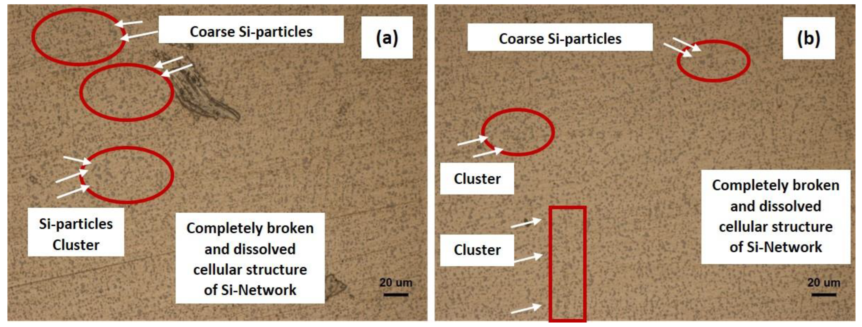
3.3. Microstructure and EDX Analysis of Heat-Exposure Specimens

Due to the rapid melting and rapid solidification cycles of the process, the microstructural aspect creates a stronger influence on mechanical behavior due to the generation of fine cellular grain structure enriched with Si nano size particle/network in the as-built condition. While taking the references from the studies on solution treatment and age hardening; the large-size globalized Si particles are formed in the microstructure with the loss of the interconnected network [33]. This ultimately causes a growth in the Si-particles that further induces ductility and softness in the Al-matrix [27]. Possibly, a similar situation of solution treatment has arisen where the network of Si-rich cell boundaries was completely broken and the Si particle network dissolves in the matrix at the application of surface heat-exposure from the gas flames. The effect of heat-exposure from the carburizing and neutral flames on the microstructure is presented in Figure 10. It is evident in Figure 10a,b that the inherited enriched Si cellular network of SLM is completely dissolved in the matrix, and even the coarser large Si particle density is quite low after the exposure from carburizing and neutral flames. However, very few coarse Si particles were observed in Figure 10a,b, which are highlighted in the form of patches and clusters. It is observed that the density of undissolved or coarse Si particles is relatively higher for the case of carburizing flame in Figure 10a than neutral flame exposure given in Figure 10b. The reason for the existence of large/coarse Si particles at a few places involved the growth of particles at the expense of smaller ones, or otherwise the incomplete dissolving of the Si-based network in the matrix.
As highlighted in Table 2, the as-built specimens offered higher resistance in terms of low mass loss due to the ultrafine cellular structure, where the supersaturated cells are decorated with the network of eutectic Si. These cell boundaries show an interconnected network consisting of eutectic Si particles with a very small amount of Mg2Si phase [34]. This characteristic microstructure is the ultimate reason for offering the low mass loss in the wear testing. However, when the surface exposed to heat through gas flames, shows a completely different microstructure; the signs of the Si cellular structure completely vanish. As highlighted in Figure 10a,b, a completely broken or dissolved cellular structure only existed, which is the ultimate sign and reason for showing higher mass loss after exposure to gas flames. Moreover, the cellular structure of eutectic Si is transformed into the bimodal distribution of coarse and fine particles [22], which is distributed in the matrix of microstructure given in Figure 10a,b. The more concentrated patches of coarse Si particles are gathered after carburizing flames shown in Figure 10a, which relatively offered more resistance to wear in contrast to neutral flames where the network is completely dissolved. Thus, very few signs of clustering and coarse particle patches are exhibited in Figure 10b.
The cross-sectional examination of the wear tracks is conducted to assess the elemental distribution variations through elemental mapping using SEM-EDX. The obtained EDX mapped locations of the as-built, carburized, neutral, and oxidized specimens are presented in Figure 11a–h, respectively. Figure 11a,b illustrates the as-built specimen, revealing the distinct elemental Si cellular network rings, marked separately in Figure 11b. These elemental Si cellular rings are possible due to rapid cooling from the SLM process, where the supersaturated Si gets trapped in the α-Al matrix, and the remaining residual Si gets settled or segregated at the cellular formed boundaries [35]. The elemental bar intensity highlights the low peak of Si as a result of this formed supersaturated solution. In addition, the minute existence of Mg2Si is also possible at the inside melt pool boundary where Mg reacts with the eutectic Si forming Mg2Si phases at the sub-cell boundaries [36]. For this reason, the elemental mapping boundaries of Si and Mg are slightly overlapped as depicted and observable in Figure 11b.
Figure 11c,d depicted the surface EDX elemental mapping after the heat exposure to the carburizing flame. The cellular Si network is nearly eradicated after the exposure of heat, as also confirmed by optical microstructures, where the coarsening of the melt pool boundary is exhibited along with the existence of nearly circular discontinuous Si particles. As highlighted in Figure 11d, discontinuous Si elemental mapping is evident with large circular and undissolved Si particle patches. Moreover, the elemental bar intensity highlights the slightly high peak of Mg, which may be caused by the formation of Mg2Si.
However, the neutral flame mapping is presented in Figure 11e,f where the Si-rich cellular network is completely broken and transformed into coarse isolated Si particles [37]. The scattered elemental distribution of Si over the selected surface is visible in Figure 11f. The higher intensity elemental peak of Si is visible attributed to the amount of Si rejected from the α-Al matrix to form coarse particles of Si at the expense and dissolution of the eutectic Si-network. This effect caused a declination in the supersaturation of the α-Al matrix due to the precipitation of dissolved Si, which is the ultimate reason for showing higher mass loss values, as provided in Table 2. Furthermore, with the oxidized flame (Figure 11g,h), the Si content underwent complete dissolution, resulting in the elimination of the Si network structure and the formation of coarse Si particles due to the agglomeration and the precipitation from the saturated α-Al matrix [38]. A discontinuous and scattered coarse Si elemental distribution is visible in Figure 11h. The formation of Mg2Si was also drastically reduced in the oxidized flame, indicating a significant alteration in the elemental composition.

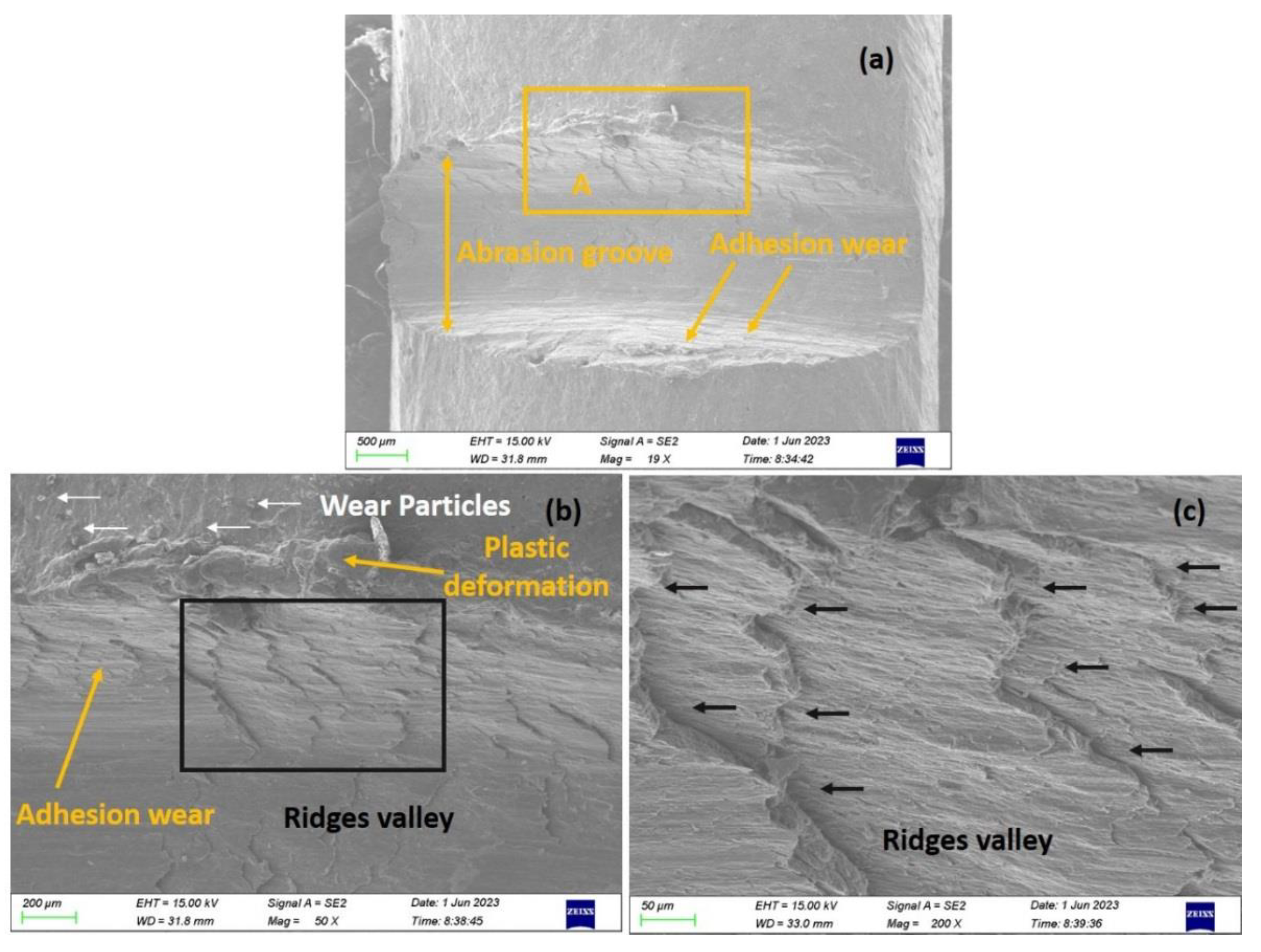
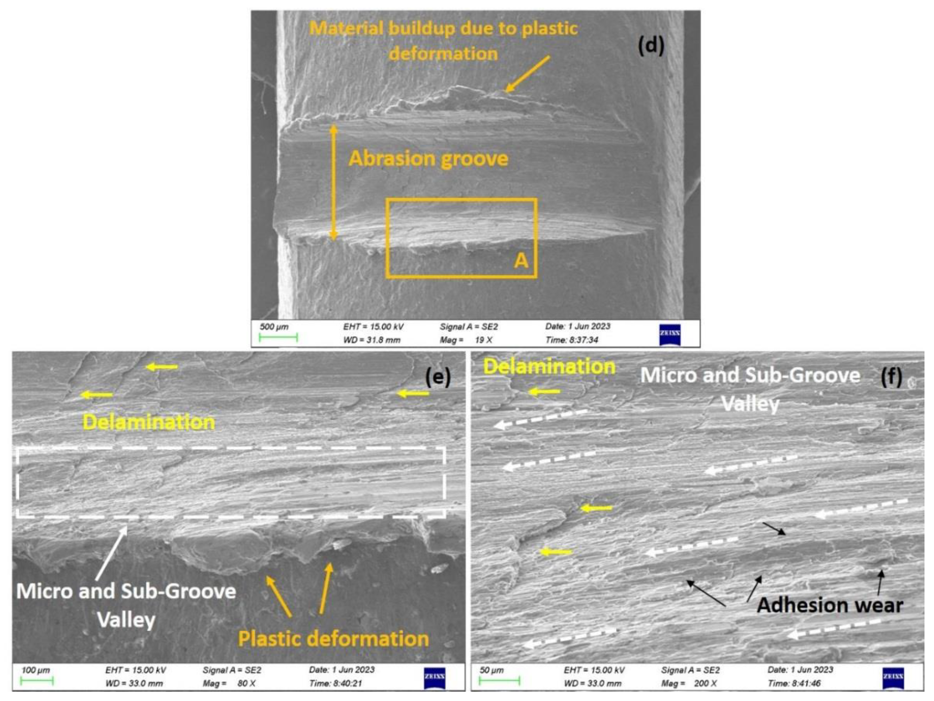
3.4. SEM Analysis of the Worn Surfaces after Heat-Exposure

To better understand the effect of surface remelting through oxyacetylene flames on the wear mechanism of AlSi10Mg, the developed morphologies concerning the wear types on wear tracks are analyzed through SEM images as given in Figure 12, Figure 13 and Figure 14 for carburizing, neutral, and oxidizing flames, respectively. Figure 12a–c shows the wear track developed for a 24 mm radius while Figure 12d–f is for a 30 mm radius after the exposure from carburizing flame. Before discussing the exact wear mechanism, the width of the abrasion groove for 24 mm is greater than 30 mm as superficially a deep furrow is visible in the middle of Figure 12a. In contrast, a well-confined groove in terms of the shallow furrow is obtained for 30 mm radius as shown in Figure 12d, which caused a dominant decrement in the percentage of mass loss from 3.617% to 3.09% from 24 mm to 30 mm radius as also given in Table 2.
The evaluation of the wear mechanism as a function of carburizing flame against the observed SEM images is illustrated in Figure 12a–f. The obtained wear patterns indicated that adhesive wear is the prevalent wear mechanism for both the wear tracks. However, starting with the generation of an abrasion groove that developed against the interaction of the sliding pin and the SLM-prepared remelted surface; the wearing away of the material is the abrasion that grew in the ellipsoidal shape along the major axis in the same direction of sliding. This ellipsoidal-shaped abrasion groove is highlighted in Figure 12a,d for 24 mm and 30 mm radii and shows extensive plastic deformation. A large amount of adhered material on the side of grooves has existed that buildup significant material [39], which is often characteristic for the cases of pin-on-disc testing. This material buildup and plastic deformation are categorically highlighted in Figure 12a and Figure 12d, and also in the enlarged detail of Section-A in Figure 12b and Figure 12e respectively. This ultimately suggests that the adhesion is the predominant wear mechanism [40] and causes a higher mass loss specifically for the 24 mm radius.
The magnified SEM images shown in Figure 12b,c,e,f revealed no traces of abrasive wear except a limited region highlighted in Figure 12b, which showed the signs of wear debris adjacent to the wear track boundary. In contrast, a minute percentage of delamination existed in Figure 12e,f whereas no significant sign in Figure 12a–c. Furthermore, the sideways examination of the groove revealed the ridges and micro-groove valleys for 24 mm and 30 mm radii highlighted in Figure 12b and Figure 12e that are magnified in Figure 12c and Figure 12f, respectively. It is important to note that the wear testing is executed under an externally applied normal load with a repeated number of cycles that cause extreme deformation where the sliding pin is able to penetrate from the top surface and create an abrasion groove at the center of the track [41]. This pin also pushed the upper edge of the groove and created the sequential ridges valley while traveling circumferentially as highlighted in Figure 12c. The ridges are concentrated centrally seem like microcutting, and reduce gradually as moving towards the trailing edge of the specimen. On the contrary, the wear track of 30 mm showed micro or sub-groove valley as depicted in Figure 12f, which is a sign of difficulty in the plastic deformation and improved resistance as highlighted in Table 2. The morphology of this magnified region exhibited the absence of coarse deep ploughing as previously observed in Figure 12c, and showed the patches of craters and scratching against the sliding surface as depicted in Figure 12e.
The representative wear attributes of neural flame surface remelting for both radii are presented in Figure 13a–d. The SEM images in Figure 13a–c showed extended widths of the wear tracks in comparison with the previous case of carburizing. Visually a deep ploughing furrow is obtained for 24 mm radius wear track along with decent plastic flow during sliding, while relatively constrictive but widened furrow plastic deformation is observed for 30 mm radius. Again, the observed morphologies indicated in Figure 13a,c are ubiquitous towards the adhesive wear mechanism. The magnified images of the worn surfaces given in Figure 13b,d also revealed other in-detailed topology features. A considerable portion of Figure 13b is covered with deep adhesive wear characteristics with severe ploughing and macro ridges at the trailing edge. Moreover, the complete ploughing of grains that pulled out from the surface and generated the small pits is also highlighted in Figure 13b. The track shown in Figure 13a represents the creation of higher contact stresses by frictional heat induced during sliding [42] in contrast to a larger radius track of 30 mm. In addition, the magnified image in Figure 13d exhibits the signs of delamination prominently at various places. While the sideways examination of a similar track in Figure 13d, the limited ridges valley also developed by pushing the pin along the edge of the abrasion groove.
The effect of oxidizing flame remelting on the worn surface of the SLM-prepared specimen is shown in Figure 14a–d. The presented wear tracks are developed against the static pin and the rotating fixture carrying the SLM specimens at 24 mm and 30 mm radii given in Figure 14a,b and Figure 14c,d respectively. The soft aluminum surface developed an abrasion groove against oxidizing flames similar to the previous cases of carburizing and neutral flames. The condition of the developed wear tracks for oxidizing flames is not as severe as obtained for the neutral flame, and comparable to carburizing flame but with observable topological features. The widths of the obtained tracks are possibly similar to Figure 12a–f but the extended transferred sideways are obtained for 24 mm and 30 mm radii with a nature of longitudinal rough patches accumulated on either side of abrasion tracks given in Figure 14a and Figure 14c, respectively. Each sideway is brightly self-illuminated on either side of the groove and is also highlighted in Figure 14a,c.
The magnified images of both the radii are given in Figure 14b,d, where the considerable portion is based on adhesive wear along with the directional macro linear grooves that were produced due to sliding wear against the reciprocating nature of contact. The typical characteristic behavior of adhesive wear is prevalent due to the nature of two contacting surfaces; where the transfer or loss of mass from a less strengthened surface in the dry non-lubricating condition exhibits. Based on this wear mechanism, categorically the lump of buildup material against the plastic deformation on either side of the wear tracks is represented in Figure 14a,c. Moreover, the high contact stressed wear track of a 24 mm radius also demonstrated the visible fissures of pullout on the eve of opened cracks available at the boundary of grooves, which is highlighted, with black color, in Figure 14a–c. Furthermore, the creation of good passive coating also resists and prolongs the removal of material under the fixed RPM for wear testing, here the generation of a dense aluminum oxide layer due to the condition provided in the oxidizing flame also existed. This layer also acts like a solid lubricant and helps in reducing the coefficient of friction [10], and is further indicative of minor abrasive wear contribution. The presence of pullout and ejected oxide particles from the wear track surface is evident in Figure 14c,d as separately highlighted with white color arrows. As depicted in Table 2, the difference in mass loss for oxidizing is almost comparable to carburizing and lesser than the neutral flames, which is possible due to the generation of oxide flame that contributes as a passive blocking while the bright extended sideways could be due the slight contribution of abrasive wear along with adhesion.

4. Conclusions

The characteristics, features, and behavior of developed wear tracks of the SLM fabricated AlSi10Mg alloy specimens have been studied considering the pin-on-disc wear testing. The following conclusions are drawn after the heat exposure from different flames oxyacetylene gas welding:
  • The wear testing of the as-built SLM specimen exhibits the lowest mass loss of all of the surface exposure specimens through different flames. Moreover, the smallest block of mass loss also belongs to the as-built SLM condition with almost identical values at 24 mm and 30 mm radii, respectively.
  • The wear behavior of SLM AlSi10Mg specimens exhibits nuanced responses to distinct heat exposures. Notably, the neutral flame produces the highest mass losses at both the 24 mm and 30 mm radii. However, carburizing and oxidizing flames yield lower mass losses in contrast to the neutral flame but higher values than the as-built condition specimens. These findings underscore the influence of heat exposure on wear characteristics, offering insights for tailored applications.
  • By comparing the macro morphology of the developed wear tracks; the width of the built-in SLM specimens is sharp and consistent throughout the length though an elliptical impression; which is more widened at the center for the cases of heat exposure specimens. Even, the signs of extreme deformation with a bit more deeper and larger in width tracks for all of the flames, including carburizing, neutral, and oxidizing, are available along with badly affected dimensional stability.
  • The observed wear pattern for all types of flames indicated that adhesive wear is the prevalent wear mechanism for both the wear tracks. A large amount of adhered amount exhibited on both sideways due to plastic deformation along with the ridges valley and micro-groove valley at 24 mm and 30 mm radii for carburizing flame are the highlighted features. However, severe ploughing, macro ridges, ploughing of grains, and delamination are the wear mechanism features of the neutral flame. SEM analysis revealed extended sideways carrying rough patches of macro linear groove in the direction of sliding for the oxidizing flame.

Author Contributions

Conceptualization, M.A., M.M. and N.A.; methodology, M.A., M.M., R.K. and J.D.; validation, M.M., M.S. and A.M.; writing—original draft preparation, M.A., M.M., M.A.K., R.K. and A.K.S.; writing—review and editing, M.A., M.M., N.A., M.S., R.K., J.D. and A.M.; visualization, M.M.; supervision, M.A. All authors have read and agreed to the published version of the manuscript.

Funding

The work was supported and funded by the Deanship of Scientific Research at Imam Mohammad Ibn Saud Islamic University (IMSIU) (grant number IMSIU-RG23104).

Institutional Review Board Statement

Not applicable.

Informed Consent Statement

Not applicable.

Data Availability Statement

The original contributions presented in the study are included in the article.

Conflicts of Interest

The authors declare no conflict of interest.

References

  1. Duran, M.M.; Moro, G.; Zhang, Y.; Islam, A. 3D printing of silicone and polyurethane elastomers for medical device application: A review. Adv. Ind. Manuf. Eng. 2023, 7, 100125. [Google Scholar] [CrossRef]
  2. Pramanik, J.; Brahma, B.; Pradhan, S.; Senapati, M.R.; Samal, A.K.; Pani, S.K. 3D printing application in biomedical—A review. Mater. Today Proc. 2023, in press. [Google Scholar] [CrossRef]
  3. Ajibola, O.O.; Adebayo, A.O.; Borisade, S.G.; Owa, A.F.; Ige, O.O. Characterisation and tribological behaviour of zinc-aluminium (Zn-Al) alloy under dry sliding reciprocating ball on disk tribometer. Mater. Today Proc. 2021, 38, 1140–1146. [Google Scholar] [CrossRef]
  4. Haque, M.S.; Rokon, S.N.; Kaiser, M.S. Strengthening and softening behavior of non-heat-treatable aluminum alloys subject to deformation and annealing treatment. Mater. Today Proc. 2023, 82, 151–157. [Google Scholar] [CrossRef]
  5. Wang, L.F.; Sun, J.; Yu, X.L.; Shi, Y.; Zhu, X.G.; Cheng, L.Y.; Liang, H.H.; Yan, B.; Guo, L.J. Enhancement in mechanical properties of selectively laser-melted AlSi10Mg aluminum alloys by T6-like heat treatment. Mater. Sci. Eng. A 2018, 734, 299–310. [Google Scholar] [CrossRef]
  6. Wang, J.; Zhu, R.; Liu, Y.; Zhang, L. Understanding melt pool characteristics in laser powder bed fusion: An overview of single-and multi-track melt pools for process optimization. Adv. Powder Mater. 2023, 2, 100137. [Google Scholar] [CrossRef]
  7. Read, N.; Wang, W.; Essa, K.; Attallah, M.M. Selective laser melting of AlSi10Mg alloy: Process optimisation and mechanical properties development. Mater. Des. (1980–2015) 2015, 65, 417–424. [Google Scholar]
  8. Dinaharan, I.; Gladston, J.A.K.; Selvam, J.D.R.; Jen, T.C. Influence of particle content and temperature on dry sliding wear behavior of rice husk ash reinforced AA6061 slurry cast aluminum matrix composites. Tribol. Int. 2023, 183, 108406. [Google Scholar] [CrossRef]
  9. Akram, S.; Babutskyi, A.; Chrysanthou, A.; Montalvão, D.; Whiting, M.J.; Pizurova, N. Improvement of the wear resistance of nickel-aluminium bronze and 2014-T6 aluminium alloy by application of alternating magnetic field treatment. Wear 2021, 480, 203940. [Google Scholar] [CrossRef]
  10. Bukhari, S.M.A.; Husnain, N.; Siddiqui, F.A.; Anwar, M.T.; Khosa, A.A.; Imran, M.; Qureshi, T.H.; Ahmad, R. Effect of laser surface remelting on Microstructure, mechanical properties and tribological properties of metals and alloys: A review. Opt. Laser Technol. 2023, 165, 109588. [Google Scholar] [CrossRef]
  11. Li, F.; Zhang, T.; Chen, C.; Liu, X.; Zhou, K. Constructing an ultrahard layer on the surface of Ti3AlC2 ceramics via electron beam surface remelting. Mater. Lett. 2021, 301, 130315. [Google Scholar] [CrossRef]
  12. Ciubotariu, C.R.; Frunzăverde, D.; Mărginean, G.; Șerban, V.A.; Bîrdeanu, A.V. Optimization of the laser remelting process for HVOF-sprayed Stellite 6 wear resistant coatings. Opt. Laser Technol. 2016, 77, 98–103. [Google Scholar] [CrossRef]
  13. Wu, Z.; Wang, W.; Li, X.; Yan, M.; Li, Y. Microstructure and mechanical properties of Ti-6Al-4V prepared by nickel preplating and electron beam surface remelting. J. Mater. Process. Technol. 2019, 271, 420–428. [Google Scholar] [CrossRef]
  14. Li, Y.; Song, P.; Wang, W.; Lei, M.; Li, X. Microstructure and wear resistance of a Ni-WC composite coating on titanium grade 2 obtained by electroplating and electron beam remelting. Mater. Charact. 2020, 170, 110674. [Google Scholar] [CrossRef]
  15. Chari, V.S.; Jhavar, S. Surface properties modification of SS316L using plasma beam remelting (PBR) and its applications in additive manufacturing. Trans. Indian Natl. Acad. Eng. 2021, 6, 1017–1025. [Google Scholar] [CrossRef]
  16. Pan, W.X.; Meng, X.; Li, G.; Fei, Q.X.; Wu, C.K. Feasibility of laminar plasma-jet hardening of cast iron surface. Surf. Coat. Technol. 2005, 197, 345–350. [Google Scholar] [CrossRef]
  17. Clark, D.A.; Johnson, W.S. Temperature effects on fatigue performance of cold expanded holes in 7050-T7451 aluminum alloy. Int. J. Fatigue 2003, 25, 159–165. [Google Scholar] [CrossRef]
  18. Lacarac, V.D.; Smith, D.J.; Pavier, M.J. The effect of cold expansion on fatigue crack growth from open holes at room and high temperature. Int. J. Fatigue 2001, 23, 161–170. [Google Scholar] [CrossRef]
  19. Jabra, J.; Romios, M.; Lai, J.; Lee, E.; Setiawan, M.; Ogren, J.R.; Clark, R.; Oppenheim, T.; Es-Said, O.S.; Lee, E.W.; et al. The effect of thermal exposure on the mechanical properties of 2099-T6 die forgings, 2099-T83 extrusions, 7075-T7651 plate, 7085-T7452 die forgings, 7085-T7651 plate, and 2397-T87 plate aluminum alloys. J. Mater. Eng. Perform. 2006, 15, 601–607. [Google Scholar] [CrossRef]
  20. Ceschini, L.; Morri, A.; Morri, A.; Rotundo, F.; Toschi, S. Heat treatment response and influence of overaging on mechanical properties of C355 cast aluminum alloy. Metall. Ital. 2014, 5, 11–17. [Google Scholar]
  21. Zhou, L.; Mehta, A.; Schulz, E.; McWilliams, B.; Cho, K.; Sohn, Y. Microstructure, precipitates and hardness of selective-ly laser melted AlSi10Mg alloy before and after heat treatment. Mater. Charact. 2018, 143, 5–17. [Google Scholar] [CrossRef]
  22. Alghamdi, F.; Song, X.; Hadadzadeh, A.; Shalchi-Amirkhiz, B.; Mohammadi, M.; Haghshenas, M. Post heat treatment of additive manufactured AlSi10Mg: On silicon morphology, texture and small-scale properties. Mater. Sci. Eng. A 2020, 783, 139296. [Google Scholar] [CrossRef]
  23. Tonolini, P.; Montesano, L.; Tocci, M.; Pola, A.; Gelfi, M. Wear behavior of AlSi10Mg alloy produced by laser-based powder bed fusion and gravity casting. Adv. Eng. Mater. 2021, 23, 2100147. [Google Scholar] [CrossRef]
  24. Park, T.H.; Baek, M.S.; Sohn, Y.; Lee, K.A. Effect of post-heat treatment on the wear properties of AlSi10Mg alloy manufactured by selective laser melting. Arch. Metall. Mater. 2020, 65, 1073–1080. [Google Scholar] [CrossRef]
  25. Zhang, Y.; Majeed, A.; Muzamil, M.; Lv, J.; Peng, T.; Patel, V. Investigation for macro mechanical behavior explicitly for thin-walled parts of AlSi10Mg alloy using selective laser melting technique. J. Manuf. Process. 2021, 66, 269–280. [Google Scholar] [CrossRef]
  26. Majeed, A.; Muzamil, M.; Lv, J.; Liu, B.; Ahmad, F. Heat treatment influences densification and porosity of AlSi10Mg alloy thin-walled parts manufactured by selective laser melting technique. J. Braz. Soc. Mech. Sci. Eng. 2019, 41, 267. [Google Scholar] [CrossRef]
  27. Majeed, A.; Muzamil, M.; Khan, M.A.; Malik, E.H.; Huzaifa, M.; Lv, J.; Dar, N.U. Comprehensive Mechanical Behavior of Thin-Walled Additively-Manufactured Parts of AlSi10Mg by SLM in As-Built, Post-Solution, and Aging Treatment Conditions. JOM 2023, 75, 3067–3082. [Google Scholar] [CrossRef]
  28. ASTM G99-05; Standard Test Method for Wear Testing with a Pin-on-Disk Apparatus. ASTM International: West Conshohocken, PA, USA, 2006; Volume 5, pp. 1–6.
  29. Hammond, V.; Schuch, M.; Bleckmann, M. The influence of a process interruption on tensile properties of AlSi10Mg samples produced by selective laser melting. Rapid Prototyp. J. 2019, 25, 1442–1452. [Google Scholar] [CrossRef]
  30. Maconachie, T.; Leary, M.; Zhang, J.; Medvedev, A.; Sarker, A.; Ruan, D.; Lu, G.; Faruque, O.; Brandt, M. Effect of build orientation on the quasi-static and dynamic response of SLM AlSi10Mg. Mater. Sci. Eng. A 2020, 788, 139445. [Google Scholar] [CrossRef]
  31. Galy, C.; Le Guen, E.; Lacoste, E.; Arvieu, C. Main defects observed in aluminum alloy parts produced by SLM: From causes to consequences. Addit. Manuf. 2018, 22, 165–175. [Google Scholar] [CrossRef]
  32. Tabatabaei, N.; Zarei-Hanzaki, A.; Moshiri, A.; Abedi, H.R. The effect of heat treatment on the room and high temperature mechanical properties of AlSi10Mg alloy fabricated by selective laser melting. J. Mater. Res. Technol. 2023, 23, 6039–6053. [Google Scholar] [CrossRef]
  33. Strauß, L.; Lübbecke, S.; Löwisch, G. Optimizing the Solution Annealing of Additively Manufactured AlSi10Mg. HTM J. Heat Treat. Mater. 2023, 78, 300–316. [Google Scholar] [CrossRef]
  34. Li, W.; Li, S.; Liu, J.; Zhang, A.; Zhou, Y.; Wei, Q.; Yan, C.; Shi, Y. Effect of heat treatment on AlSi10Mg alloy fabricated by selective laser melting: Microstructure evolution, mechanical properties and fracture mechanism. Mater. Sci. Eng. A 2016, 663, 116–125. [Google Scholar] [CrossRef]
  35. Wei, P.; Wei, Z.Y.; Chen, Z.; Du, J.; He, Y.Y.; Li, J.F.; Zhou, Y.T. The AlSi10Mg samples produced by selective laser melting: Single track, densification, microstructure and mechanical behavior. Appl. Surf. Sci. 2017, 408, 38–50. [Google Scholar] [CrossRef]
  36. Fousová, M.; Dvorský, D.; Michalcová, A.; Vojtěch, D. Changes in the microstructure and mechanical properties of additively manufactured AlSi10Mg alloy after exposure to elevated temperatures. Mater. Charact. 2018, 137, 119–126. [Google Scholar] [CrossRef]
  37. Wei, P.; Chen, Z.; Zhang, S.; Fang, X.; Lu, B.; Zhang, L.; Wei, Z. Effect of T6 heat treatment on the surface tribological and corrosion properties of AlSi10Mg samples produced by selective laser melting. Mater. Charact. 2021, 171, 110769. [Google Scholar] [CrossRef]
  38. Kempf, A.; Hilgenberg, K. Influence of heat treatments on AlSi10Mg specimens manufactured with different laser powder bed fusion machines. Mater. Sci. Eng. A 2021, 818, 141371. [Google Scholar] [CrossRef]
  39. McConnell, J.E.; Segall, A.E.; Eden, T.J. The Dry Sliding Behavior of Al2O3 Transformed, Hypereutectic, 2xxx, and 7xxx, Aluminum Alloys Under Simulated Wire–Rope Induced Wear. Tribol. Trans. 2006, 49, 563–573. [Google Scholar] [CrossRef]
  40. D’Amato, C.; Buhagiar, J.; Betts, J.C. Tribological characteristics of an A356 aluminium alloy laser surface alloyed with nickel and Ni–Ti–C. Appl. Surf. Sci. 2014, 313, 720–729. [Google Scholar] [CrossRef]
  41. Rajamure, R.S.; Vora, H.D.; Gupta, N.; Karewar, S.; Srinivasan, S.G.; Dahotre, N.B. Laser surface alloying of molybdenum on aluminum for enhanced wear resistance. Surf. Coat. Technol. 2014, 258, 337–342. [Google Scholar] [CrossRef]
  42. Zhang, Y.; Lei, G.; Luo, K.; Chen, P.; Kong, C.; Yu, H. Tribological behavior of high-entropy alloy particle reinforced aluminum matrix composites and their key impacting factors. Tribol. Int. 2022, 175, 107868. [Google Scholar] [CrossRef]
Figure 1. Roadmap to execute the overall work; categorically highlighting the experimentation execution, and processing and post-processing of obtained results.
Coatings 14 00252 g001
Figure 2. Schematic representation of process starting from the SLM machine where the powder is fused layer by layer in the building orientation in the vertical z-axis direction on checkboard.
Coatings 14 00252 g002
Figure 3. Execution sequence of wear testing; (a) wear testing machine, (b) fixture having two slots placed onto the disc holder is separately (c) tachometer, (d) controller box.
Coatings 14 00252 g003
Figure 4. Difference of mass loss block for all three gas flames and as-built condition specimen at 24 mm and 30 mm radii.
Coatings 14 00252 g004
Figure 5. Macro images of the As-built specimens wear tracks; (a) the top view of both the wear tracks grooves (b) wear track images with scale (c) side view morphology of the grooves.
Coatings 14 00252 g005
Figure 6. Macro wear track images of the heat exposure specimens through the carburizing flame; (a) the top view of the specimen when placed flat on the surface (b) wear track image with scale (c) side view morphology of the wear tracks grooves.
Coatings 14 00252 g006
Figure 7. Macro wear track images of the heat exposure specimens through the neutral flame; (a) the top view of the specimen when placed flat on the surface (b) wear track image with scale (c) side view morphology of the wear tracks grooves.
Coatings 14 00252 g007
Figure 8. Macro wear track images of the heat exposure specimens through the oxidizing flame; (a) the top view of the specimen when placed flat on the surface (b) wear track image with scale (c) side view morphology of the wear tracks grooves.
Coatings 14 00252 g008
Figure 9. SEM images of the Cross-Sections after wear testing; (a,b) as-built specimen at 30 mm and 24 mm radii, respectively; (c,d) heat exposure from carburizing gas flame, tested at 30 mm and 24 radii respectively; (e,f) heat exposure from neutral gas flame, tested at 30 mm and 24 radii respectively; (g,h) heat exposure from oxidizing gas flame, tested at 30 mm and 24 radii, respectively.
Coatings 14 00252 g009
Figure 10. Optical microstructure after heat-exposure from gas flames (a) carburizing flame exposure, (b) neutral flame exposure.
Coatings 14 00252 g010
Figure 11. EDX elemental mapping of the cross section of Wear track with different flames; (a,b) as-built condition SLM, (c,d) carburizing flame exposure, (e,f) neutral flame exposure, and (g,h) oxidizing flame exposure.
Coatings 14 00252 g011
Figure 12. SEM wear track images of carburizing flame; (ac) belong to 24 mm radius, (a) elliptical abrasion groove against dry sliding, (b) expanded view of the area of track [A], (c) expanded view of the ridges valley; (df) belong to 30 mm radius, (d) elliptical abrasion groove against dry sliding, (e) expanded view of the area of track [A], (f) expanded view of the micro and sub-groove valley highlighted in Figure 12e.
Coatings 14 00252 g012aCoatings 14 00252 g012b
Figure 13. SEM wear track images of neutral flame; (a,b) belong to 24 mm radius, (a) deep ploughing abrasion groove against dry sliding, (b) expanded view of the trailing edge highlighting ploughing and macro ridges; (c,d) belong to 30 mm radius, (c) abrasion groove highlighting adhesion, (d) bottom sideway expanded view.
Coatings 14 00252 g013
Figure 14. SEM wear track images of oxidizing flame; (a,b) belong to 24 mm radius, (a) abrasion groove at the center, (b) expanded view of bottom sideway; (c,d) belong to 30 mm radius, (c) abrasion groove highlighting both the sideways, (d) expanded view of trailing edge.
Coatings 14 00252 g014
Table 1. Processing parameters and their values for the SLM processing [27].
Technical/Processing ParametersValues/Description
Laser power (kW)0.32
Scan Speed (m/s)0.90
Hatch distance (mm)0.08
Slice thickness (mm)0.03
Beam focus diameter (mm)0.08
Scanning strategy67° with checkerboard
Building directionVertical
Building substrate plate280.0 mm × 280.0 mm × 70.0 mm (L × W × H)
Table 2. Shows the mass difference and percentage of mass loss when wear testing is performed at 24 mm and 30 mm radius.
Wear Testing RadiusSpecimenMass before Wear Testing (g)Mass after Wear Testing (g)Mass Difference (g)Percentage of Mass Loss (%)
Wear Testing at R = 24 mmAs-Built0.4980.4850.0132.610
Carburizing0.4700.4530.0173.617
Neutral0.4700.4500.0204.255
Oxidizing0.4740.4570.0173.586
Wear Testing at R = 30 mmAs-Built0.4850.4730.0122.474
Carburizing0.4530.4390.0143.090
Neutral0.4530.4360.0173.752
Oxidizing0.4570.4410.0163.501
Disclaimer/Publisher’s Note: The statements, opinions and data contained in all publications are solely those of the individual author(s) and contributor(s) and not of MDPI and/or the editor(s). MDPI and/or the editor(s) disclaim responsibility for any injury to people or property resulting from any ideas, methods, instructions or products referred to in the content.

