
Microstructure and Impact Toughness of Laser-Arc Hybrid Welded Joint of Medium-Thick TC4 Titanium Alloy

Abstract
1. Introduction
2. Experimental Details
2.1. Material
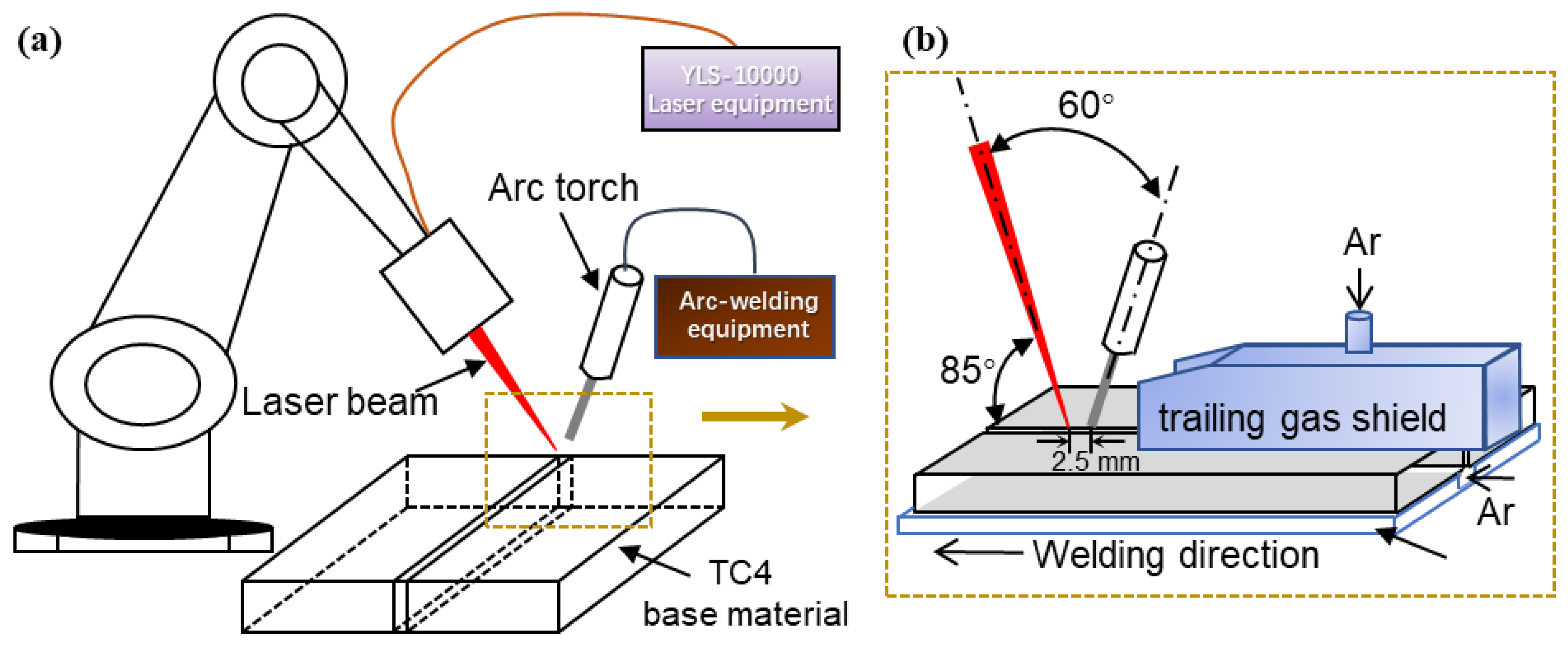
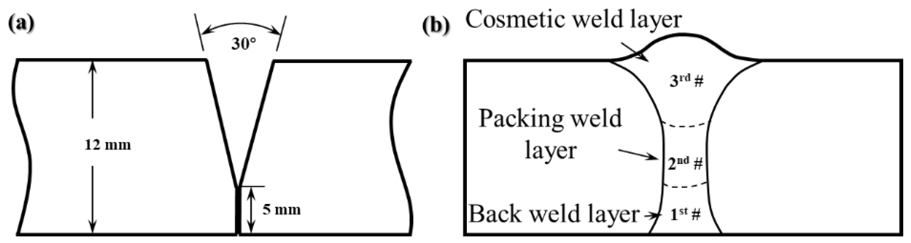
2.2. Laser-Arc Hybrid Welding System
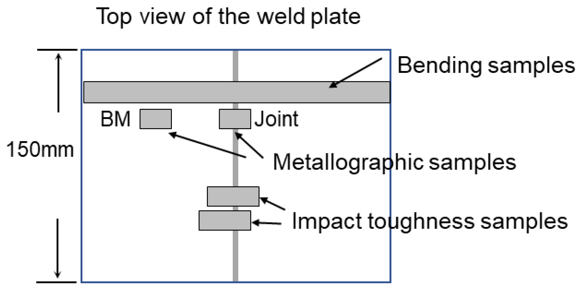
2.3. Microstructure, Hardness, Bending and Impact Properties Tests
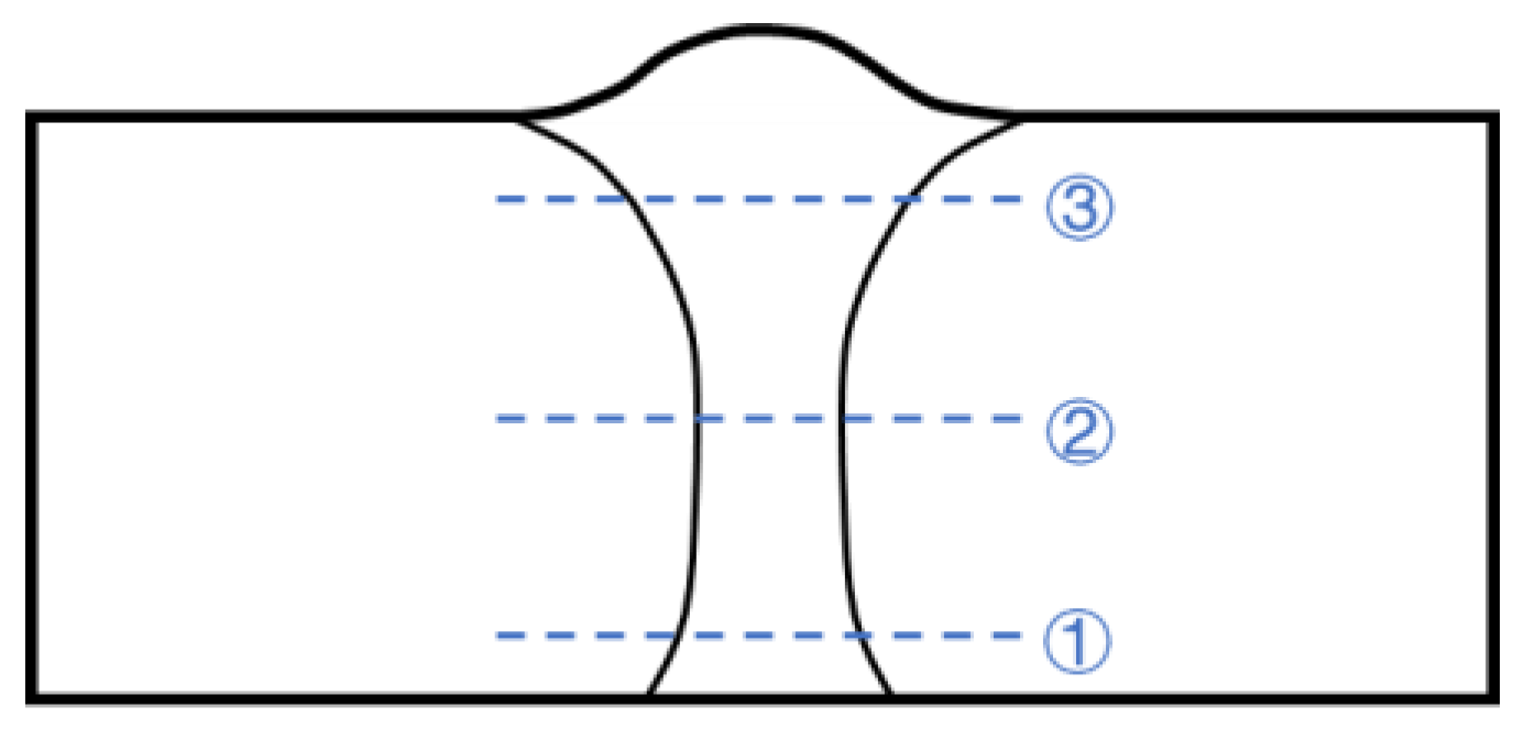
2.3.1. Microstructure Characterization
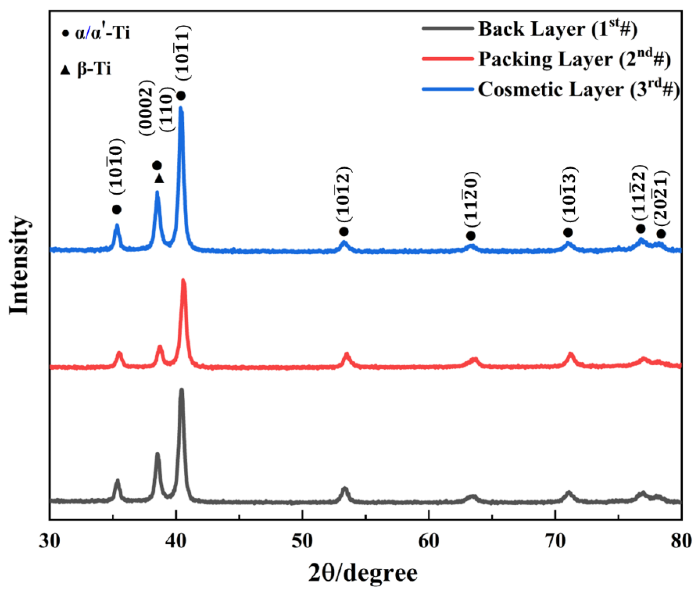
2.3.2. XRD Test
2.3.3. Hardness Test
2.3.4. Bending Test
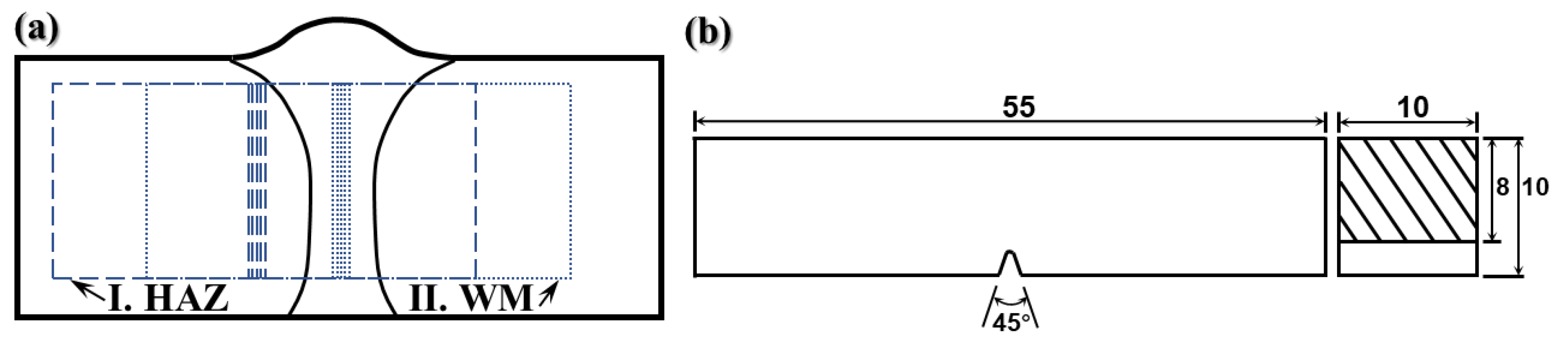
2.3.5. Impact Toughness Test
3. Results and Discussion
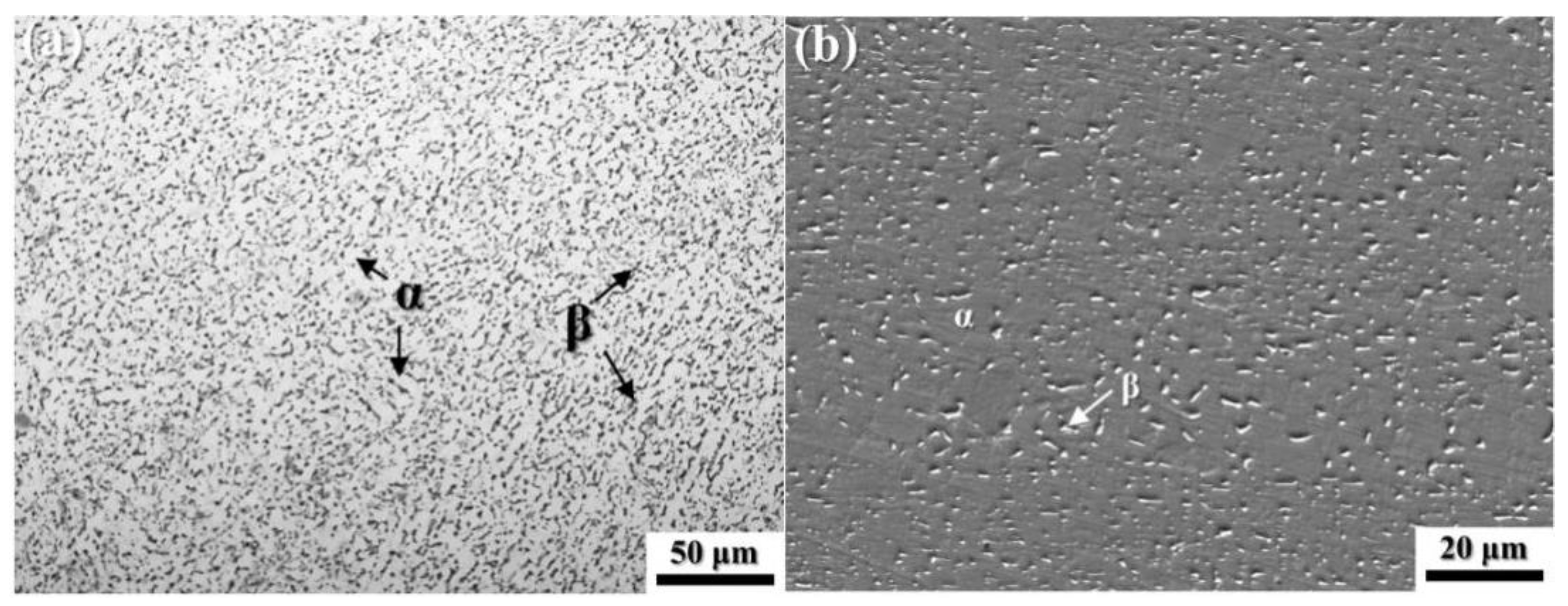
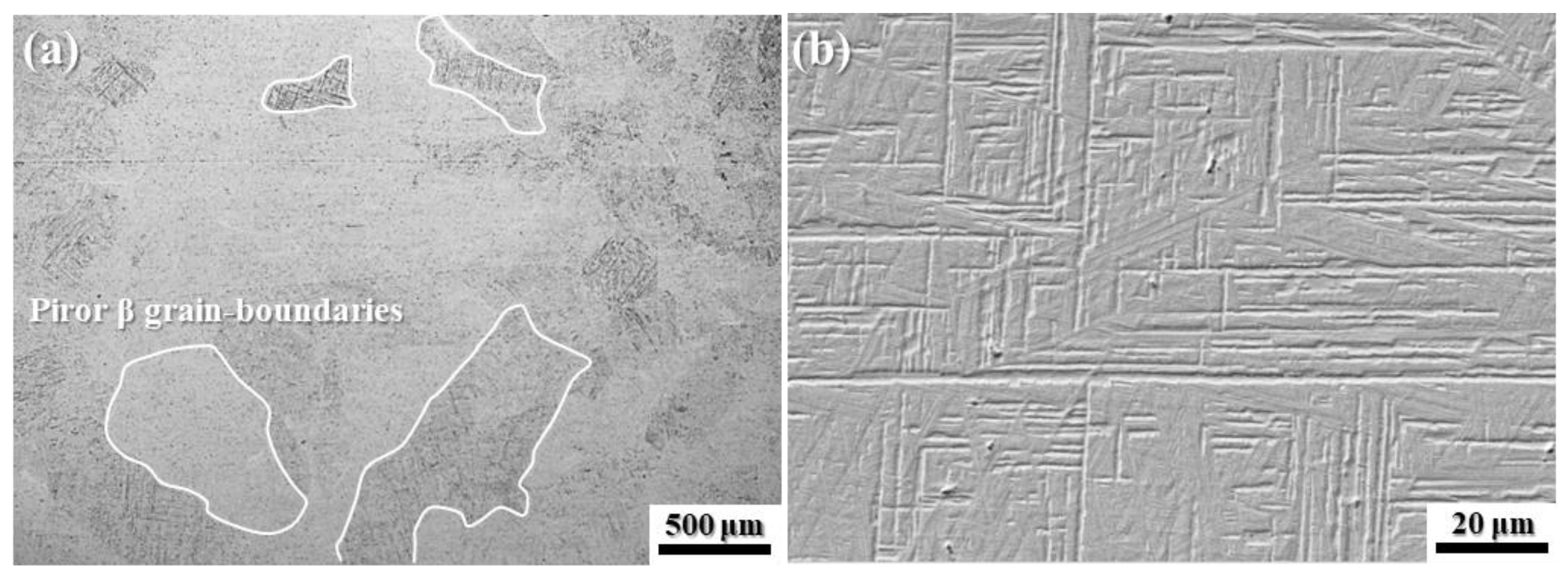
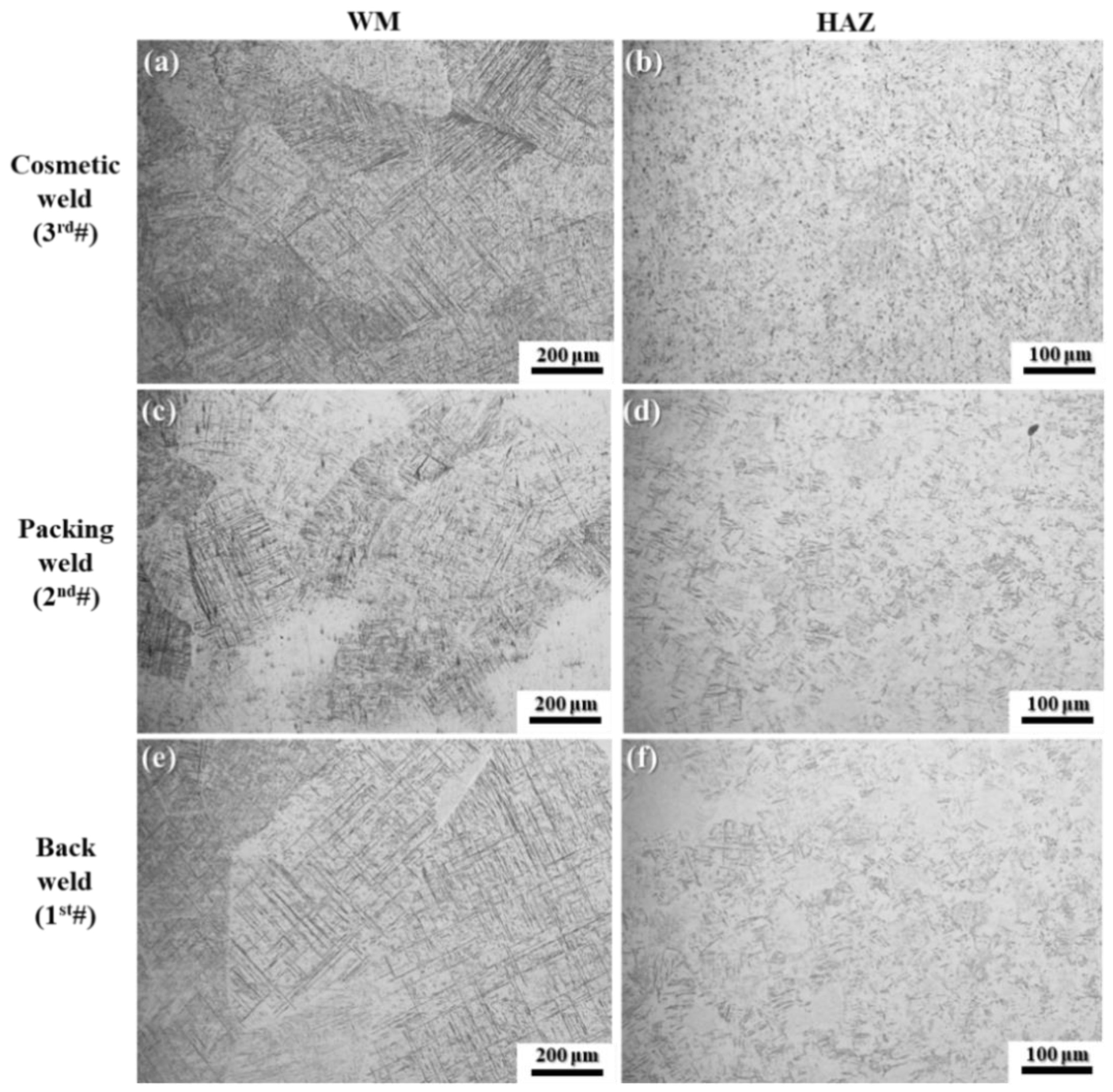
3.1. Microstructure Analysis
3.2. XRD Analysis
3.3. Mechanical Properties of the Joint
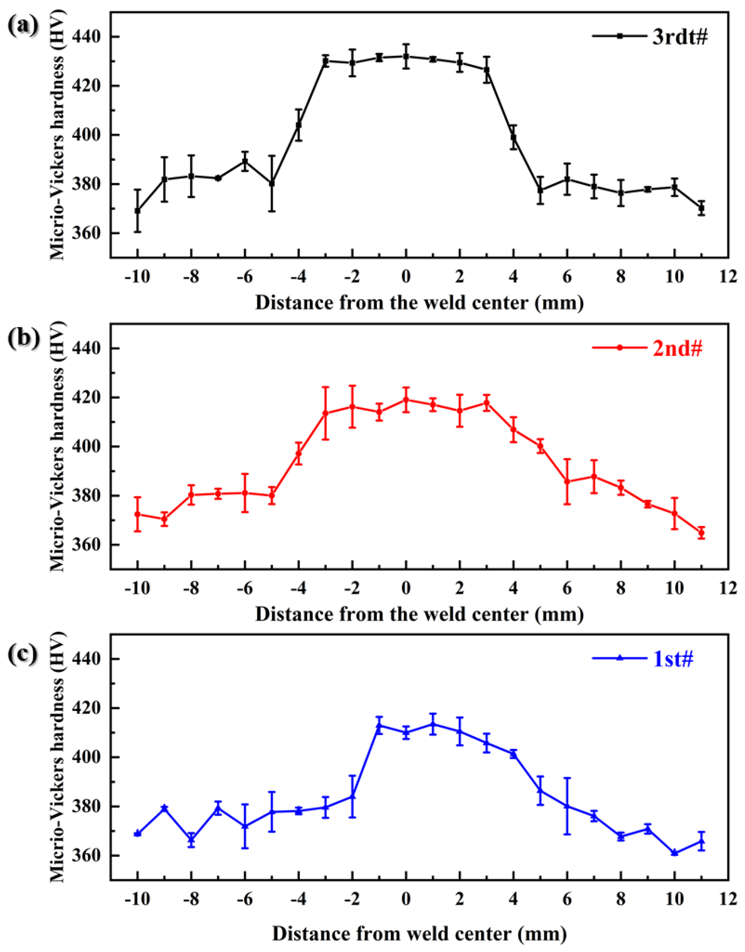
Hardness Analysis
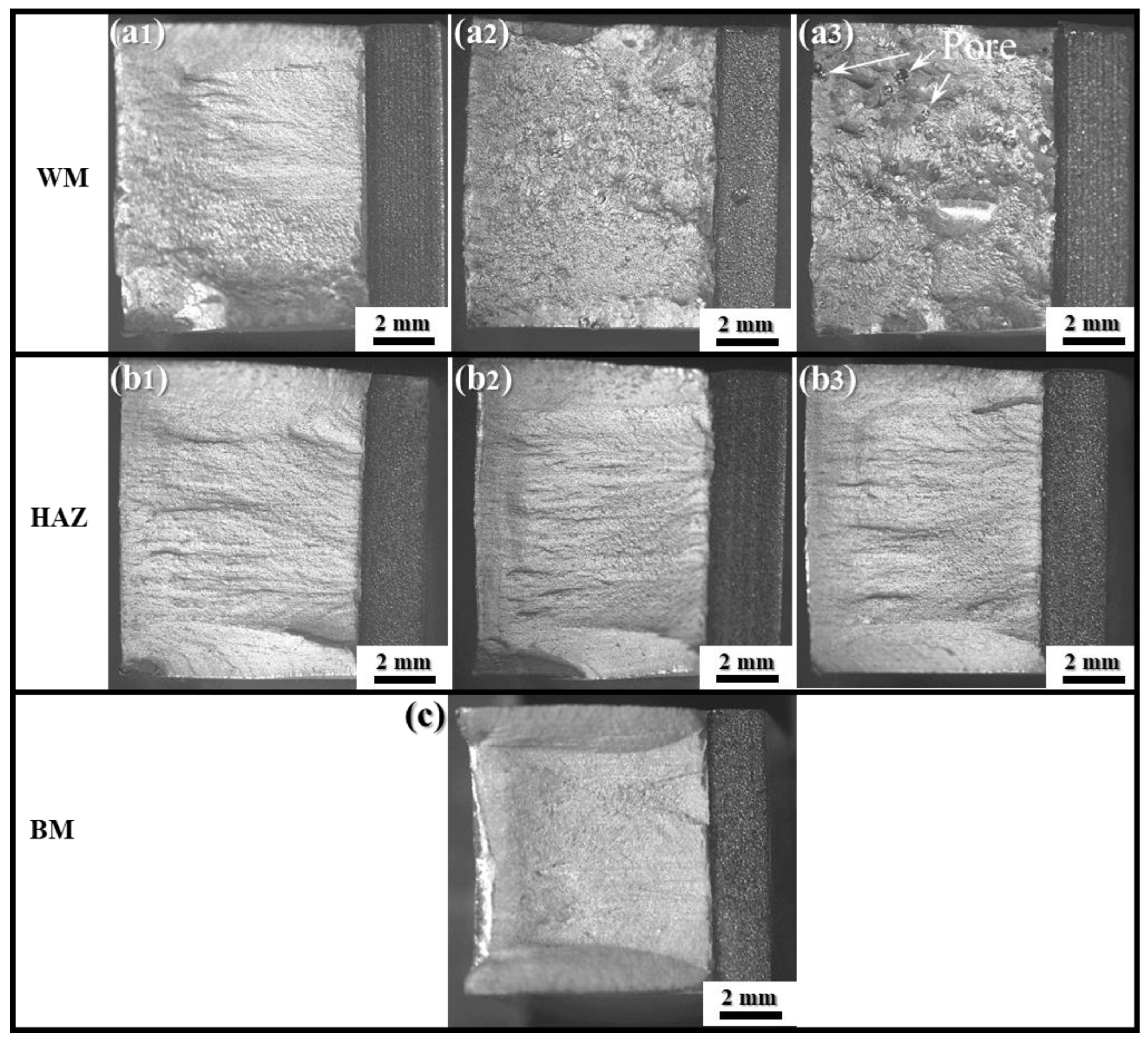
3.4. Bending Test
3.5. Room-Temperature Impact Toughness
3.5.1. Impact Toughness Analysis
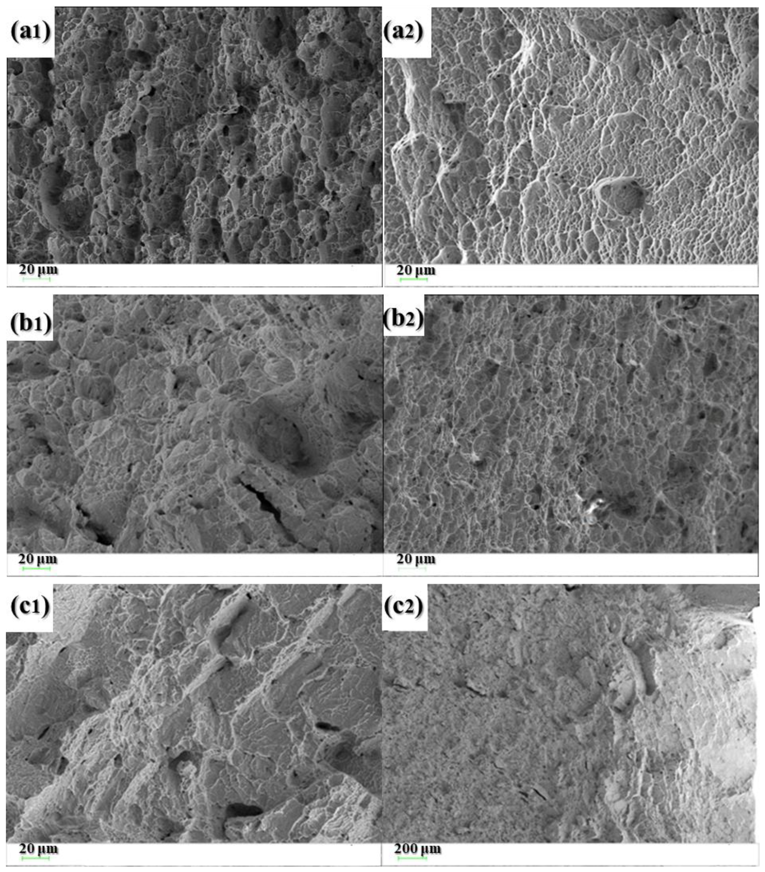
3.5.2. Failure Mechanism of Impact Performance
4. Conclusions
Author Contributions
Funding
Institutional Review Board Statement
Data Availability Statement
Conflicts of Interest
References
- Auwal, S.T.; Ramesh, S.; Yusof, F.; Manladan, S.M. A review on laser beam welding of titanium alloys. Int. J. Adv. Manuf. Technol. 2018, 97, 1071–1098. [Google Scholar] [CrossRef]
- Guo, P.; Zhao, Y.; Zeng, W.; Hong, Q. The effect of microstructure on the mechanical properties of TC4-DT titanium alloys. Mater. Sci. Eng. A 2013, 563, 106–111. [Google Scholar] [CrossRef]
- Cui, C.; Hu, B.; Zhao, L.; Liu, S. Titanium alloy production technology, market prospects and industry development. Mater. Des. 2011, 32, 1684–1691. [Google Scholar] [CrossRef]
- Wen, P.; Yelkenci, D.; Chen, J.; Chang, B.; Du, D.; Shan, J. Numerical analysis of the effect of welding positions on formation quality during laser welding of TC4 titanium alloy parts in aerospace industry. J. Laser Appl. 2019, 31, 022401. [Google Scholar] [CrossRef]
- Schneider, A.; Gumenyuk, A.; Lammers, M.; Malletschek, A.; Rethmeier, M. Laser Beam Welding of Thick Titanium Sheets in the Field of Marine Technology. Phys. Procedia 2014, 56, 582–590. [Google Scholar] [CrossRef]
- Akman, E.; Demir, A.; Canel, T.; Sınmazçelik, T. Laser welding of Ti6Al4V titanium alloys. J. Mater. Process. Technol. 2009, 209, 3705–3713. [Google Scholar] [CrossRef]
- Sun, Y.Y.; Wang, P.; Lu, S.L.; Li, L.Q.; Nai, M.L.S.; Wei, J. Laser welding of electron beam melted Ti-6Al-4V to wrought Ti-6Al-4V: Effect of welding angle on microstructure and mechanical properties. J. Alloys Compd. 2019, 782, 967–972. [Google Scholar] [CrossRef]
- Yuan, T.; Li, Y.; Ren, X.; Jiang, X.; Zhao, P. Effect of Pulse Current on Grain Refinement in Ti6Al4V Welds during Pulsed Plasma Arc Welding. J. Mater. Eng. Perform. 2023. [Google Scholar] [CrossRef]
- Su, R.; Li, H.; Chen, H.; Wang, H.; Wang, W.; Wang, D.; Guo, J. Stability analysis and porosity inhibition mechanism of oscillating laser-arc hybrid welding process for medium-thick plate TC4 titanium alloy. Opt. Laser Technol. 2024, 174, 110569. [Google Scholar] [CrossRef]
- Junaid, M.; Baig, M.N.; Shamir, M.; Khan, F.N.; Rehman, K.; Haider, J. A comparative study of pulsed laser and pulsed TIG welding of Ti-5Al-2.5Sn titanium alloy sheet. J. Mater. Process. Technol. 2017, 242, 24–38. [Google Scholar] [CrossRef]
- Pragatheswaran, T.; Rajakumar, S.; Balasubramanian, V. Optimization of the weld characteristics of plasma-arc welded titanium alloy joints: An experimental study. Mater. Manuf. Process. 2021, 37, 896–907. [Google Scholar] [CrossRef]
- Gao, F.; Li, P.; Jiang, P.; Liao, Z. The effect of constraint conditions on microstructure and properties of titanium alloy electron beam welding. Mater. Sci. Eng. A 2018, 721, 117–124. [Google Scholar] [CrossRef]
- Chen, J.; Li, H.; Liu, Y.; Zhao, X.; Cai, Y.; Chen, H.; Chen, Y.; Feng, A.; Wang, H.; Sun, Z. Deformation behavior and microstructure characteristics of the laser-welded Ti-6Al-4V joint under variable amplitude fatigue. Mater. Charact. 2023, 196, 112606. [Google Scholar] [CrossRef]
- Li, R.; Li, Z.; Zhu, Y.; Rong, L. A comparative study of laser beam welding and laser–MIG hybrid welding of Ti–Al–Zr–Fe titanium alloy. Mater. Sci. Eng. A 2011, 528, 1138–1142. [Google Scholar] [CrossRef]
- Chatterjee, S.; Mahapatra, S.S.; Bharadwaj, V.; Upadhyay, B.N.; Bindra, K.S.; Thomas, J. Parametric appraisal of mechanical and metallurgical behavior of butt welded joints using pulsed Nd:YAG laser on thin sheets of AISI 316. Opt. Laser Technol. 2019, 117, 186–199. [Google Scholar] [CrossRef]
- Nam, K.; Ki, H. One camera-based laser keyhole welding monitoring system using deep learning. J. Manuf. Process. 2023, 104, 17–27. [Google Scholar] [CrossRef]
- Chatterjee, S.; Mahapatra, S.S.; Lamberti, L.; Pruncu, C.I. Prediction of welding responses using AI approach: Adaptive neuro-fuzzy inference system and genetic programming. J. Braz. Soc. Mech. Sci. Eng. 2022, 44, 53. [Google Scholar] [CrossRef]
- Zhan, X.; Liu, J.; Chen, J.; Peng, Q.; Wei, Y.; Zhao, Y. Parameter optimization of multi-pass multi-layer MIG welded joint for invar alloy. Int. J. Adv. Manuf. Technol. 2016, 87, 601–613. [Google Scholar] [CrossRef]
- Su, X.; Tao, W.; Chen, Y.; Fu, J. Microstructure and Tensile Property of the Joint of Laser-MIG Hybrid Welded Thick-Section TC4 Alloy. Metals 2018, 8, 1002. [Google Scholar] [CrossRef]
- Brandizzi, M.; Satriano, A.A.; Tricarico, L. CO2 Laser—MIG Hybrid Welding of Titanium Alloy. Adv. Mater. Res. 2011, 264–265, 1270–1280. [Google Scholar] [CrossRef]
- Chen, S.; Luo, S.; Yu, H.; Geng, H.; Xu, G.; Li, R.; Tian, Y. Effect of beam defocusing on porosity formation in laser-MIG hybrid welded TA2 titanium alloy joints. J. Manuf. Process. 2020, 58, 1221–1231. [Google Scholar] [CrossRef]
- Fan, H.; Zhou, P.; Li, J.; Huang, J.; Ni, Y.; Hui, Y. Microstructure and Mechanical Properties of Arc Zone and Laser Zone of TC4 Titanium Alloy Laser–TIG Hybrid Welded Joint. Metals 2022, 12, 1854. [Google Scholar] [CrossRef]
- Yang, H.Y.; Xu, X.K.; Ba, X.L.; Tao, X.K.; Liu, L.M. Process and mechanism of low power laser-double arc welding of titanium alloy plate. Trans. China Weld. Inst. 2022, 43, 12–19. [Google Scholar] [CrossRef]
- Gao, M.; Chen, C.; Wang, L.; Wang, Z.; Zeng, X. Laser-Arc Hybrid Welding of Dissimilar Titanium Alloy and Stainless Steel Using Copper Wire. Metall. Mater. Trans. A 2015, 46, 2007–2020. [Google Scholar] [CrossRef]
- Yu, J.; Cai, C.; Xie, J.; Chen, Z.; Chen, H. Keyhole stability, arc behavior, and molten pool flow in narrow-gap oscillating laser-arc hybrid welding of titanium alloy. Int. J. Heat Mass Transf. 2024, 220, 124922. [Google Scholar] [CrossRef]
- Liu, J.; Zhan, X.; Gao, Z.; Yan, T.; Zhou, Z. Microstructure and stress distribution of TC4 titanium alloy joint using laser-multi-pass-narrow-gap welding. Int. J. Adv. Manuf. Technol. 2020, 108, 3725–3735. [Google Scholar] [CrossRef]
- Zhan, X.; Bu, H.; Gao, Q.; Yan, T.; Ling, W. Temperature field simulation and grain morphology on laser welding-brazing between Ti-6Al-4V and 1050 aluminum alloy. Mater. Res. Express 2019, 6, 056551. [Google Scholar] [CrossRef]
- Liu, J.; Yang, T.; Zhuang, Y.; Li, L.; Huang, M.; Su, X.; Dong, S. Micro-crystallographically revealing the plasticity-evolved behaviors of thick Ti–6Al–4V laser-arc hybrid welded joint. J. Mater. Res. Technol. 2024, 28, 459–467. [Google Scholar] [CrossRef]
- Rominiyi, A.L.; Mashinini, P.M. A critical review of microstructure and mechanical properties of laser welded similar and dissimilar titanium alloy joints. J. Adv. Join. Process. 2024, 9, 100191. [Google Scholar] [CrossRef]
- Matsumoto, H.; Yoneda, H.; Sato, K.; Kurosu, S.; Maire, E.; Fabregue, D.; Konno, T.J.; Chiba, A. Room-temperature ductility of Ti–6Al–4V alloy with α′ martensite microstructure. Mater. Sci. Eng. A 2011, 528, 1512–1520. [Google Scholar] [CrossRef]
- Zhang, Y.; Xin, R.; Guo, B.; Wang, K.; Liu, Q. Influence of alternate grain boundary α on the development of Widmanstätten microstructure in TC21 Ti alloy. Mater. Charact. 2021, 177, 111162. [Google Scholar] [CrossRef]
- Ma, Y.; Youssef, S.S.; Feng, X.; Wang, H.; Huang, S.; Qiu, J.; Lei, J.; Yang, R. Fatigue crack tip plastic zone of α + β titanium alloy with Widmanstatten microstructure. J. Mater. Sci. Technol. 2018, 34, 2107–2115. [Google Scholar] [CrossRef]
- Wei, P.; Wu, M.; Liu, D.; Liang, Y.; Zhao, Z. Face Bend Property of 7N01-T4 Aluminum Alloy MIG Welded Joint by Using Different Welding Wires. Metals 2022, 12, 873. [Google Scholar] [CrossRef]
- Luo, C.; Zhao, Y.; Cao, Y.; Zhao, L.; Shan, J. Effect of laser heat treatment on bending property of laser welded joints of low-alloy ultra-high strength steel. J. Laser Appl. 2019, 31, 032011. [Google Scholar] [CrossRef]
- Liu, Y.; Chen, Q.; Chen, J.; Yang, J.; Dong, S. Development of a novel fabricating thin-walled TA2 titanium tube via high-frequency induction welding. Prog. Nat. Sci. Mater. Int. 2024, (in press). [Google Scholar] [CrossRef]
- Balasubramanian, T.S.; Balakrishnan, M.; Balasubramanian, V.; Manickam, M.A.M. Influence of welding processes on microstructure, tensile and impact properties of Ti-6Al-4V alloy joints. Trans. Nonferrous Met. Soc. China 2011, 21, 1253–1262. [Google Scholar] [CrossRef]
- Huang, J.L.; Warnken, N.; Gebelin, J.-C.; Strangwood, M.; Reed, R.C. On the mechanism of porosity formation during welding of titanium alloys. Acta Mater. 2012, 60, 3215–3225. [Google Scholar] [CrossRef]
- Dewangan, S.; Mohapatra, S.K.; Sharma, A. An assessment into mechanical properties and microstructural behavior of TIG welded Ti-6Al-4V titanium alloy. Grey Syst. Theory Appl. 2020, 10, 281–292. [Google Scholar] [CrossRef]
- Sun, L.; Wang, M.; Huang, L.; Fang, N.; Wu, P.; Huang, R.; Xu, K.; Wang, X.; Qin, J.; Li, S.; et al. Comparative study on laser welding thick-walled TC4 titanium alloy with flux-cored wire and cable wire. Materials 2023, 16, 1509. [Google Scholar] [CrossRef] [PubMed]
- Bagheri, F.; Madoliat, R.; Sedighi, M.; Asgari, A. Rubber-assisted pre-hemming process: A parametric study. J. Manuf. Process. 2019, 38, 328–337. [Google Scholar] [CrossRef]
- Esfahani Yeganeh, V.; Li, P. Effect of beam offset on microstructure and mechanical properties of dissimilar electron beam welded high temperature titanium alloys. Mater. Des. 2017, 124, 78–86. [Google Scholar] [CrossRef]


| Element | Al | V | Fe | C | N | H | O | Ti |
|---|---|---|---|---|---|---|---|---|
| TC4 alloy | 6.2 | 4.05 | 0.13 | 0.016 | 0.007 | 0.0008 | 0.131 | Bal. |
| TC4 welding wire | 5.96 | 4.01 | 0.10 | 0.012 | 0.007 | 0.0001 | 0.126 | Bal. |
| Yield Stress Rp0.2 (MPa) | Ultimate Stress Rm (MPa) | Elongation A (%) | |
|---|---|---|---|
| TC4 alloy | 922 | 986 | 13.8 |
| TC4 welding wire | 895 | 993 | 15.5 |
| Number | Welding Pass | Laser Power (kW) | Welding Speed (mm/s) | Wire Feed Rate (m/min) |
|---|---|---|---|---|
| 1st # | Back weld layer | 4500 | 10 | 10 |
| 2nd # | Packing weld layer | 4000 | 10 | 9 |
| 3rd # | Cosmetic weld layer | 6000 | 16 | 15 |
| Number | Mode | Bending Angle (°) | Bending Force (kN) | Average Force (kN) | Standard Deviation |
|---|---|---|---|---|---|
| 1-1 | Face bending | 9.4 | 30.05 | 30.02 | 0.08 |
| 2-1 | 14.8 | 29.90 | |||
| 3-1 | 15.7 | 30.10 | |||
| 1-2 | Root bending | 9.6 | 31.41 | 30.96 | 0.69 |
| 2-2 | 13.2 | 31.49 | |||
| 3-2 | 25.1 | 29.98 |
| Number | WM | HAZ | BM |
|---|---|---|---|
| 1 | 33.1 | 34.0 | 34.0 |
| 2 | 31.0 | 30.7 | 33.0 |
| 3 | 27.8 | 35.2 | 33.5 |
| Average (J) | 30.6 | 33.3 | 33.5 |
| Standard Deviation | 2.18 | 1.90 | 0.41 |
Disclaimer/Publisher’s Note: The statements, opinions and data contained in all publications are solely those of the individual author(s) and contributor(s) and not of MDPI and/or the editor(s). MDPI and/or the editor(s) disclaim responsibility for any injury to people or property resulting from any ideas, methods, instructions or products referred to in the content. |
© 2024 by the authors. Licensee MDPI, Basel, Switzerland. This article is an open access article distributed under the terms and conditions of the Creative Commons Attribution (CC BY) license (https://creativecommons.org/licenses/by/4.0/).
Share and Cite
Luo, P.; Feng, W.; Zu, G.; Luo, L.; Xiao, J. Microstructure and Impact Toughness of Laser-Arc Hybrid Welded Joint of Medium-Thick TC4 Titanium Alloy. Coatings 2024, 14, 395. https://doi.org/10.3390/coatings14040395
Luo P, Feng W, Zu G, Luo L, Xiao J. Microstructure and Impact Toughness of Laser-Arc Hybrid Welded Joint of Medium-Thick TC4 Titanium Alloy. Coatings. 2024; 14(4):395. https://doi.org/10.3390/coatings14040395
Chicago/Turabian StyleLuo, Peng, Wanxi Feng, Gang Zu, Linyin Luo, and Jun Xiao. 2024. "Microstructure and Impact Toughness of Laser-Arc Hybrid Welded Joint of Medium-Thick TC4 Titanium Alloy" Coatings 14, no. 4: 395. https://doi.org/10.3390/coatings14040395
APA StyleLuo, P., Feng, W., Zu, G., Luo, L., & Xiao, J. (2024). Microstructure and Impact Toughness of Laser-Arc Hybrid Welded Joint of Medium-Thick TC4 Titanium Alloy. Coatings, 14(4), 395. https://doi.org/10.3390/coatings14040395