Article

Microstructure, Mechanical Properties, and Lead–Bismuth Eutectic Corrosion Behaviors of FeCrAlY-Al2O3 Nanoceramic Composite Coatings

1
Key Laboratory of Radiation Physics and Technology of Ministry of Education, Institute of Nuclear Science and Technology, Sichuan University, Chengdu 610064, China
2
Science and Technology on Reactor System Design Technology Laboratory, Nuclear Power Institute of China, Chengdu 610213, China
*
Authors to whom correspondence should be addressed.
Coatings 2024, 14(4), 393; https://doi.org/10.3390/coatings14040393
Submission received: 23 February 2024 / Revised: 17 March 2024 / Accepted: 22 March 2024 / Published: 27 March 2024
(This article belongs to the Section Ceramic Coatings and Engineering Technology)

Abstract

:
Seven FeCrAlY-Al2O3 nanoceramic composite coatings are deposited on F/M steel via plasma spraying and laser remelting. A systematic investigation is conducted to examine the dependence of microstructure, mechanical properties, and lead–bismuth eutectic (LBE) corrosion resistance on the nano-Al2O3 addition and different Cr and Al contents. With the increase in Al content in FeCrAlY, gradual refinement of the coating grains occurs. The addition of nano-Al2O3 promotes the elemental segregation and precipitation of the second phase. The nano-Al2O3 notably enhances the mechanical properties of the coatings that are primarily attributed to second-phase and fine-grain strengthening. After LBE corrosion tests, intergranular corrosion morphology could be observed, where the contents of Cr and Al significantly influence the corrosion behavior of the coatings at varying temperatures.

1. Introduction

The continuous advancement of reactor technology from early prototypes to the currently designed fourth-generation reactors has led to improvements in safety, economy, lifespan, and fuel efficiency [1,2,3]. Lead-based materials, as the coolant for lead-cooled fast reactors (LFR), with their superior neutron utilization, heat transfer coefficients, and inherent safety, have sparked widespread interest in LFR [4]. However, the high-temperature corrosion of structural materials by lead–bismuth eutectic (LBE) poses several challenges such as oxidation corrosion [5], dissolution corrosion [6], and erosion [7,8,9]. This issue, which threatens the structural integrity of components like thermal insulation components during service, is a crucial limiting factor [4,10].
To overcome this challenge, various approaches have been pursued, including oxygen control [11], stainless steel material modification [12,13], development of novel materials [14,15], and surface coating technology [16]. Among these, surface coating technology offers the unique advantage of combining the benefits of both the coating and the base material, making it a widely used and effective method for protecting metal materials against corrosion. LBE-resistant coatings can be categorized into several types: ceramic coatings (Al2O3, TiN, TiAlN, Ti3SiC2, etc.) [17,18,19,20,21,22,23,24,25,26,27], alloy coatings (FeAl, FeCrAl, FeCrAlY, AlCrFeMoTi, etc.) [28,29,30,31,32,33,34,35], and others. The primary corrosion resistance mechanism of metal coatings involves the formation of a dense oxide film on the coating surface by Al, Cr, and other elements, thereby safeguarding against LBE corrosion, and these coatings exhibit a degree of self-repairing ability [29].
Among various metal coatings, FeCrAl coatings containing Cr and Al elements have gained significant attention for their good resistance to LBE corrosion [36]. The service performance of FeCrAl-based coatings is sensitive to the Cr and Al content [28]. For Cr, an optimal content can improve corrosion resistance and oxidation resistance [37], but excessive Cr can result in the formation of Cr-rich α’ brittle phases, weakening toughness and strength [38,39]. In contrast, low Cr content also compromises mechanical properties. Regarding Al, coatings with less than 4 wt% Al struggle to form a continuous oxide layer to protect against LBE corrosion [29], while higher Al content increases brittleness and degrades mechanical properties [28]. Therefore, the balance of Cr and Al elements is crucial for coatings’ mechanical properties and high-temperature LBE corrosion resistance. Additionally, Y element doping (<0.5 wt%) can slow down oxide film generation, creating a denser oxide layer [40,41,42]. Incorporating suitable nanoceramic particles (<10 wt%) can further enhance coating mechanical properties, such as hardness, wear resistance, and compressive strength [43,44,45,46]. Recently, oxide-reinforced FeCrAl matrix composite coatings have been proven to achieve good mechanical properties by adding nano-Al2O3 [47]. Overall, FeCrAlY nanoceramic composite coatings show great potential in LBE environments.
In this study, given previous research [34] and the second-generation FeCrAl alloy content, ten FeCrAlY-xAl2O3 (x = 0, 0.5, 1, 2, 4 wt%) nanoceramic composite coatings are fabricated by plasma spraying, with seven demonstrating successful enhancement via laser remelting, which is one of the promising surface coating modification methods that have been widely used in recent years. Arkajit Ghosh et al. [48] used a combination of laser rapid solidification and chemical (Sr) modification, and they synthesized fully eutectic Al–Si microstructures with heavily twinned Si nano-fibers that exhibited high hardness up to 2.9 GPa, and high compressive flow strength (~840 MPa) with stable plastic flow to ~26% plastic strain. It indicates that laser remelting modification can indeed significantly improve the mechanical properties of coatings. The mechanical properties of these seven coatings are then meticulously analyzed. Their surface morphology, microstructure, phase composition, and chemical constitution are assessed before and after undergoing LBE corrosion tests, ultimately enriching the FeCrAl coating systems for LFR applications, and offering an innovative solution for this challenging domain.

2. Experiment

2.1. Material Preparation

A 2.2 mm thickness F/M steel plate is employed as substrate and the elementary composition is listed in Table 1. Commercial nano-Al2O3 powder (>99.9 wt%, 100 nm particle size), and Fe9Cr12Al0.5Y and Fe12Cr5Al0.5Y powder (>99.9 wt%, 15–45 μm particle size, Beijing Ryubon New Material Technology, Ltd., Beijing, China) have been applied in powder preparation. Based on these two FeCrAlY powders, different contents (0, 0.5, 1, 2, 4 wt%) of nano-Al2O3 are added. The powders are mixed by mechanical alloy with a planetary ball mill (QM-QX4L, Nanjing NanDa Instrument Plant, Nanjing, China) for 30 h in argon. The ball-to-powder ratio is approximately 10:1 and the rotary speed is 300 rpm. The cooling period of 20 min is interposed to every 1 h mill time to avoid excessive warming up during milling. The surface of the substrate is ground with emery paper (#80) on a hand-held small sander to remove the oxides and cleaned with anhydrous ethanol. Subsequently, the workpiece surface is grit blasted by white corundum sand to make it rough. The coatings are fabricated by air plasma spraying (APS) (MF-P-APS-1000, GTV German, Beijing, China). The parameters of spraying are listed in Table 2. Then, laser remelting (Third generation 506R, HUIRUI, Chengdu, China) is conducted on the basis of the sprayed coatings. Laser remelting parameters will vary depending on the coating contents and only seven of the above ten coatings are remelted successfully, with the following general parameters: laser power of around 300 W; scanning rate of 5 mm/s; overlapping rate of around 15%.

2.2. Coating Characterization

Microstructure investigation of the coatings including surfaces and cross-sections is carried out using field-emission scanning electron microscopy (FESEM, Hitachi S4800, Beijing, China) with an energy-dispersive spectrometer (EDS, operating voltage 20 kV) and electron backscatter diffraction (EBSD). The phase composition of the coatings before and after LBE test is investigated by X-ray diffraction (XRD, DX-2700, Dandong Haoyuan, Dandong, China). Cu Kα radiation at a step of θ = 0.02° is used with a voltage and current of 40 kV and 30 mA, respectively. Measurements of nanohardness and modulus of elasticity on sample cross-sections are made using a nanoindenter (TI950, Bruker, Billerica, MA, USA). The maximum indentation depth is kept at 300 nm, the loading and unloading rates are 96 mN/min, and the holding time is fixed at 2 s to evaluate the mechanical properties of the coatings. The hardness and elastic modulus are calculated by the Oliver and Pharr method. Following the exposure to LBE, the adhered LBE on the surface of the coatings is cleaned with a mixed solution of ethanol, acetic acid, and hydrogen peroxide in a volume ratio of 1:1:1. The samples used for cross-section analysis are set in resin, ground to 3000 grit, and then polished to a mirror finish.

2.3. Static LBE Corrosion Test

The LBE corrosion tests are performed by exposing the F/M steel substrate with FeCrAlY-Al2O3 film coated on one side, sealing them in a quartz tube with a vacuum of 5.0 × 10⁻³ Pa to LBE, and placing them in muffle furnaces for 1000 h at 500 °C, 550 °C, and 600 °C. The specific procedures are as follows: seven types of different coating composition samples are placed in one quartz tube with a length of 25 cm to ensure a consistent corrosion environment. After placing the samples, a 2 mm thick cylindrical quartz column is thermally fused between the LBE (44.5 wt% Pb and 55.5 wt% Bi) and samples to guarantee fluidity of the LBE and ensure complete submergence of the samples without floating. Next, a cylindrical quartz column of the same size as the diameter of the tube is thermally fused on top to maintain the vacuum inside the tube. The schematic is shown in Figure 1.

3. Results and Discussion
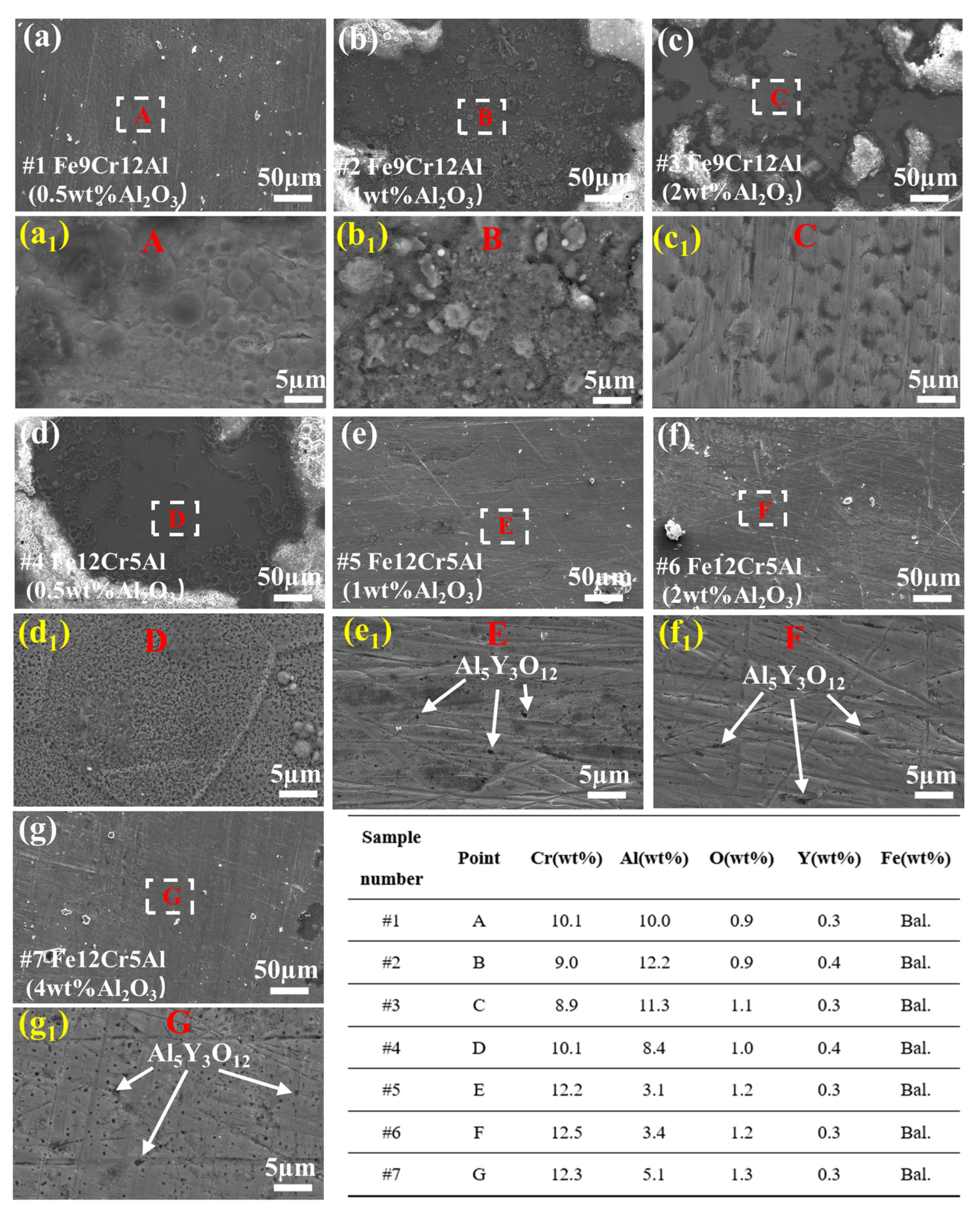
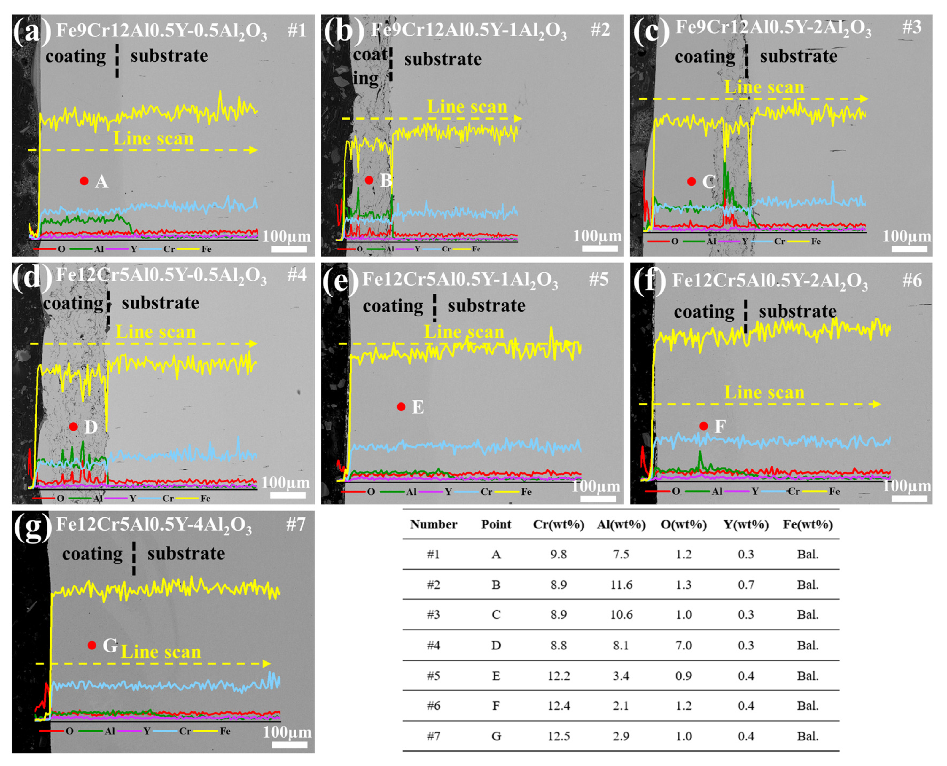
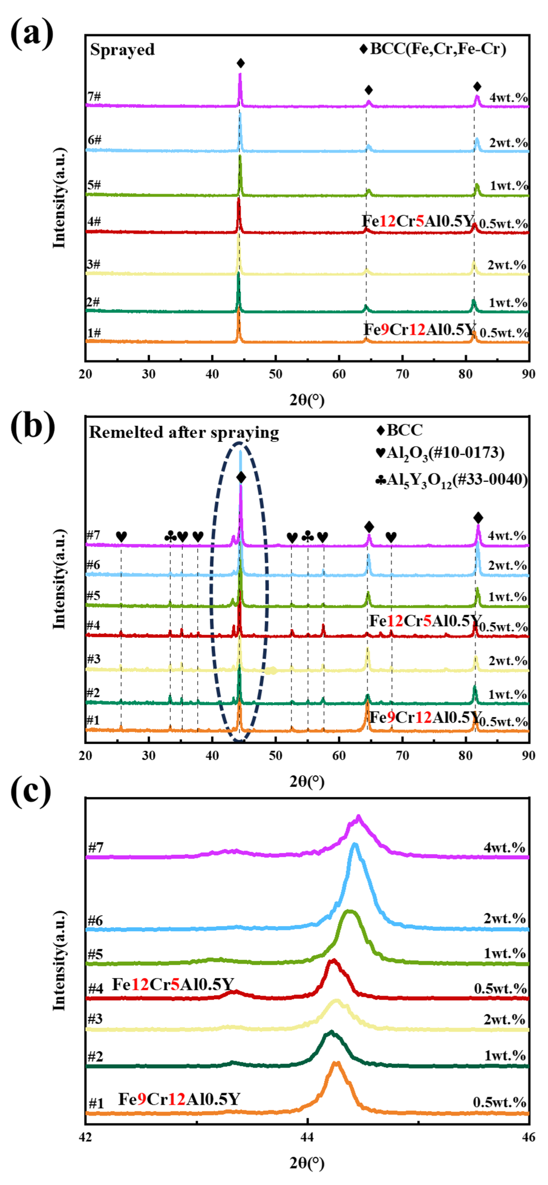
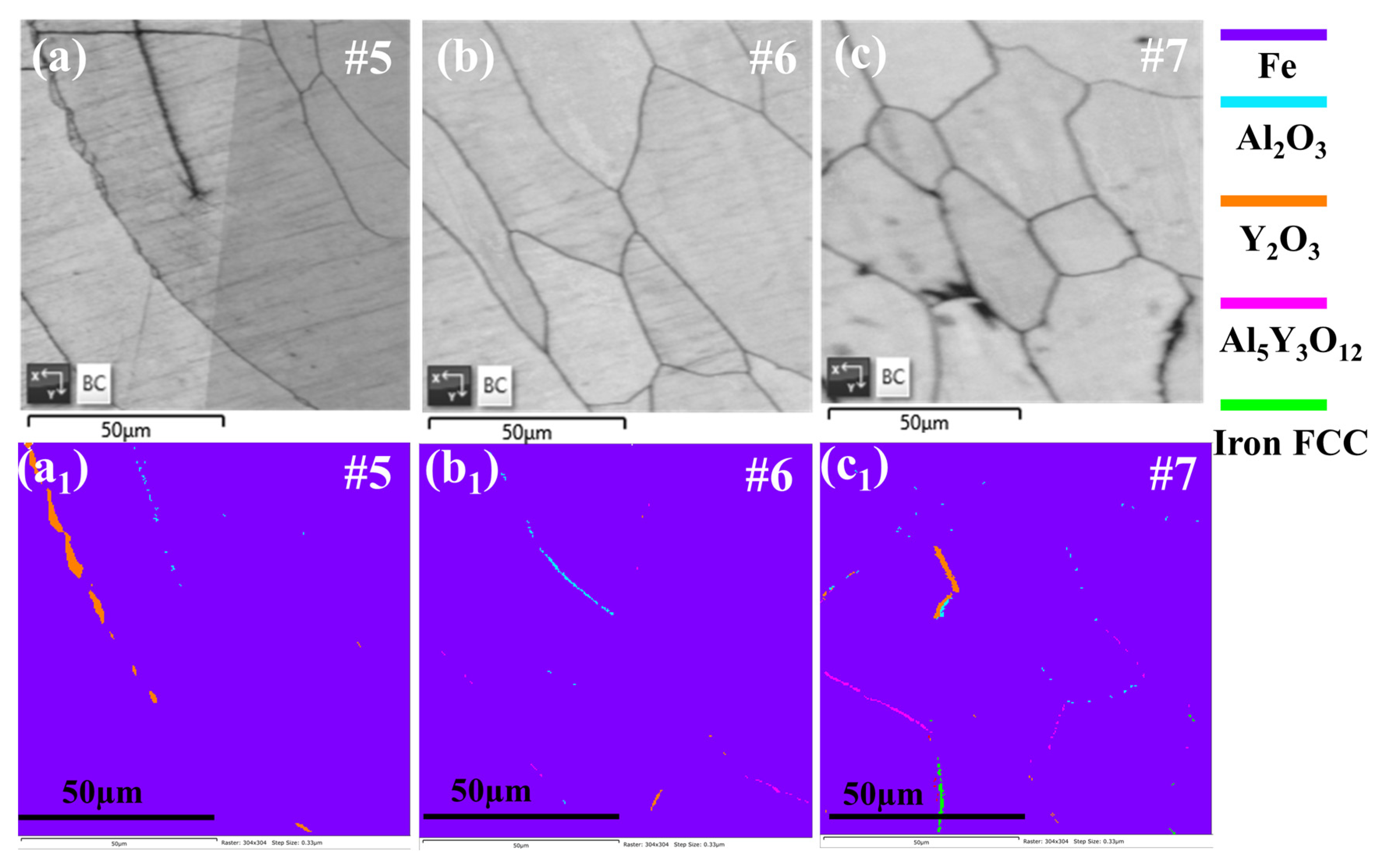
3.1. Microstructure

Figure 2 displays the cross-section images after coatings preparation. As shown in Figure 2a, the coating exhibits a lamellar structure with a number of holes inside after plasma spraying, due to the instantaneous accumulation and solidification of high-temperature molten powder particles during the spraying process. There are obvious gaps at the interface between the coating and substrate, which are caused by incompletely melted particles hitting the substrate during the spraying process. After laser remelting, the sprayed particles in the semi-melted state are completely melted, and the coating holes and gap at the interface almost disappear while the coating becomes denser and smoother and connects to the substrate as an integral like Figure 2b presents.
Figure 3 demonstrates the surface morphology of the prepared FeCrAlY-Al2O3 coatings. The surfaces of the coatings are smooth and dense. As there is no laser remelting parameter matching, samples #2, #3, and #4 are not totally remelted and thicker oxide layers are generated on the surface. Meanwhile, in the successfully remelted coatings of Fe12Cr5Al0.5Y, it can be found that the surface gradually precipitates black spots at the grain boundaries with the increasing Al2O3 addition. Combined with the following XRD patterns and phase diagrams, the black dots are Al5Y3O12. It can indicate that the addition of nano-Al2O3 could affect the amount and distribution of Al5Y3O12, which is generated by the oxidation of the Y element in the coating during laser remelting to produce Y2O3, followed by the reaction between Y2O3 and Al2O3 at high temperatures.
Figure 4 demonstrates the cross-sectional morphology and corresponding EDS line-scan results of the prepared FeCrAlY-Al2O3 coatings. The thickness of remelted seven coatings range from 200–400 µm. There are three coating–substrate interface types, described as follows: type I, where samples #2, #3, and #4 are not completely remelted, and only a thin layer (compared to the coating) of holes and gaps in the laminar structure are eliminated to become completely dense (see Figure 4b–d); type II, where irregular coating-substrate demarcation is present after remelting of sample #7, presumably due to the higher remelting power exacerbating the diffusion of elements between the coating and the substrate (see Figure 4g); and type III, where there is a clear demarcation line between the coating and the interface, and the combination with the substrate is close and sound, meaning no gaps and holes are seen (see Figure 4a,e,f).
Figure 5 shows the XRD patterns of coatings before and after laser remelting. The coatings have a BCC phase structure before laser remelting, and comparisons before and after remelting reveal that the coatings always maintain the BCC phase and all seem to be composed entirely of α-Fe phase. The diffraction peaks of Al2O3 (PDF-#10-0173) are made by a combination of added nano-Al2O3 and Al2O3 formed at high temperatures by the Al element in the coating, since such a small amount of additive should not be visible on the XRD pattern, and the appearance of the Al5Y3O12 (PDF-#33-0040) phase corroborates this conjecture. The angles of peaks are shifted with changes in the Cr and Al content of the coatings and the amount of nano-Al2O3 added, as discussed in a later section.
Figure 6 illustrates the band contrast images and the corresponding phase diagrams of typical FeCrAlY-Al2O3 coatings (#5–#7). From Figure 6a1–c1, it can be observed that the coatings have precipitated phase distribution at grain boundaries after laser remelting. Among them, the Y2O3, Al2O3, and Al5Y3O12 phases are the main precipitated phases. With the gradual increase in the addition of nano-Al2O3 in samples #5–#7, the number of precipitated phases at the grain boundaries of the coatings gradually increase, the relative content of precipitated phase Y2O3 gradually decreases while the relative content of the Al5Y3O12 precipitated phase gradually increases. With different nano-Al2O3 additions, there is a certain amount of Al2O3 phase distributed at the grain boundaries. The band contrast diagrams of the remaining samples and the corresponding phase diagrams can be seen in Figure S1.
Figure 7 shows the average grain size of the FeCrAlY-Al2O3 coatings after plasma spraying followed by laser remelting. The average grain size of the coatings is distributed in the range of 16–115 µm. The average grain size of the Fe9Cr12Al0.5Y coatings (#1–#3) is generally smaller than that of the Fe12Cr5Al0.5Y coatings (#4–#7). The grain sizes of the incompletely remelted #2 and #4 coatings are much smaller than the other coatings. Apart from the influencing factor of incomplete remelting, it can be found that the average grain size of the coatings tends to decrease with the increase in nano-Al2O3 addition.

3.2. Mechanical Properties

Figure 8 presents the hardness measurements at different depths on cross-sections of the prepared specimens. The tests are performed to evaluate the effect on coating contents and different areas after laser remelting. In general, after laser remelting of samples, three zones appear: the completely remelted zone, the heat-affected zone, and the substrate. The data are obtained and calculated from five indentation experiments. The variation in nanohardness H, elastic modulus E, H/E and H2/E3 with coating content, and distance to the coating surface is presented in Figure 8.
Figure 8a exhibits representative (a random set of data collected at each coating depth for seven samples) nanoindentation displacement–load curves for FeCrAlY-Al2O3 coatings. It shows that at the same loading rate and maximum load, the indentation depth of Fe12Cr5Al0.5Y is generally higher than that of Fe9Cr12Al0.5Y, implying lower hardness values. The variation in nanohardness of the samples at different depths is displayed in Figure 8b. The hardness values of the completely remelted zone and the heat-affected zone of the samples are significantly higher than that of the FM steel substrate (3 GPa), which are generally about twice as high as that of the substrate and can even reach up to 7.92 GPa (sample #3). In the part near the surface of the samples, the hardness values are distributed in the range of 3.63–6.54 GPa. The variation in the elastic modulus of the samples at different depths is shown in Figure 8c. The values of the elastic modulus of the different parts of the coating are distributed in the range of about 200 GPa, with a minimum of 173 GPa and a maximum of up to 222.72 GPa. In the part near the surface, the values of the elastic modulus are distributed in the range of 179.41–200.69 GPa. It can be observed that the values of hardness and modulus of elasticity of the samples indicate a tendency to increase and then decrease as the depth (i.e., the distance to the surface) increases, with an inflection point near the 200 µm point, which is the thickness of the coating. Because Fe9Cr12Al0.5Y hardness values are generally higher than that of Fe12Cr5Al0.5Y, meaning these two types of modulus elasticity values are comparable, the ratio of H/E and H3/E2, which reflects the wear resistance, is much higher in Fe9Cr12Al0.5Y than in Fe12Cr5Al0.5Y, with a twofold difference at the highest level. Thus, it can be deduced that such effective hardening must originate from the specific microstructural features produced by laser remelting and the difference in FeCrAl content.

3.3. LBE Corrosion Experiments

3.3.1. Coatings Corroded at 500 °C for 1000 h

Figure 9 demonstrates the surface SEM morphology of FeCrAlY nanoceramic composite coatings after corrosion at 500 °C for 1000 h. As shown in Figure 9a,e–g, honeycomb corrosion crater morphologies are observed. Among them, the corrosion of sample #6 is the most serious; the remaining samples demonstrate a discontinuous aluminum-rich oxide layer on the surface, and analyzed together with EDS results in Figure 10, no LBE penetration is seen in any of the coatings.
Figure 10 shows the EDS line-scan results of the Fe9Cr12Al0.5Y and Fe12Cr5Al0.5Y coatings with different nano-Al2O3 additions corroded at 500 °C for 1000 h in static LBE. From Figure 10a–d, it can be seen that there is an obvious coating–substrate Al content dividing line, and Al-rich oxide layers are generated on the surfaces and coating–substrate interfaces of samples #2 and #4 while different types of oxides are generated only on the surface of samples #3 and #7. The generation of an oxide layer at the coating–substrate interface is due to insufficient internal remelting of the coating. After the high-temperature LBE corrosion test, all seven coatings show good resistance to LBE corrosion, with no penetration of Pb and Bi in the coating. The elemental distribution of the sample cross-section after corrosion is shown in Figure S2.

3.3.2. Coatings Corroded at 550 °C for 1000 h

Figure 11 exhibits the surface morphology of the coatings corroded in LBE at 550 °C for 1000 h. Honeycomb corrosion pit morphology is also observed on samples #1, #4, #5, and #6. Unlike the 500 °C corrosion results, the corrosion morphology of sample #1 is more prominent. The corrosion of Fe12Cr5Al0.5Y coatings is improved, and the remelted sample #5 shows a lamellar oxide film after corrosion, which is also found in the remaining samples that are not remelted completely.
Figure 12 shows the EDS line-scan results of the Fe9Cr12Al0.5Y and Fe12Cr5Al0.5Y coatings with different nano-Al2O3 additions corroded at 550 °C for 1000 h in static LBE. No thick oxide layer is observed on the surface except on samples #4 and #7, but at the same time, no LBE penetration is observed, so it is assumed that a very thin Al-rich oxide layer is generated that could not be detected by the machine. All coatings show good resistance to LBE corrosion, with no penetration of Pb and Bi in the coating. The elemental distribution of the sample cross-section after corrosion is shown in Figure S3.

3.3.3. Coatings Corroded at 600 °C for 1000 h

Figure 13 shows the surface morphology of the coatings corroded in LBE at 600 °C for 1000 h. Samples #1, #5, #6, and #7 also demonstrate honeycomb corrosion pit morphology. Among them, the intergranular corrosion of sample #1 is extremely severe, and in contrast, the intergranular corrosion of samples #5, #6, and #7 is even better than that of the corrosion results at 500 °C. In the remaining samples, samples #2 and #3 generate a lamellar Al-rich oxide layer.
Figure 14 shows the EDS line-scan results of the Fe9Cr12Al0.5Y and Fe12Cr5Al0.5Y coatings with different nano-Al2O3 additions corroded at 600 °C for 1000 h in static LBE. Except for samples #4 and #7, all the coatings generated an oxide layer on the surface to block the erosion of LBE. It can be observed that both samples #1 and #3 exhibit enrichment of Y in some regions of the oxide layers. All coatings show good resistance to LBE corrosion, with no penetration of Pb and Bi in the coating. The elemental distribution of the sample cross-section after corrosion is shown in Figure S4.

4. Discussion

4.1. Microstructure of FeCrAlY-Al2O3 Composite Coatings

The coating morphology is contingent on the degree of remelting, which influences surface smoothness and density. Comparing the post-corrosion surface morphology and XRD patterns of high-Al (Fe9Cr12Al0.5Y) and low-Al (Fe12Cr5Al0.5Y) coatings, we observed similar intergranular corrosion morphologies, but smaller average grain sizes in the high-Al coatings. The main reason is grain refinement due to the precipitated phase Al5Y3O12. Al5Y3O12 can only be generated by the reaction between Al2O3 and Y2O3 at high temperatures (i.e., generated by the oxidation of elemental Y and the reaction with Al2O3 during the laser remelting procedure), which means despite the inert gas protection, a certain degree of oxidation of the coating elements occurs during laser remelting.
For the Fe9Cr12Al0.5Y samples, the intensity of the diffraction peaks decreases with increasing nano-Al2O3 content. Although the higher surface roughness of sample #2 due to incomplete remelting causes XRD pattern background enhancement, the diffraction peak’s intensity is reduced and slightly broadened at the same time. Therefore, in conjunction with Figure 7, it is reasonable to assume that the addition of nano-Al2O3 indeed leads to grain refinement.
For the Fe12Cr5Al0.5Y samples, the diffraction peaks are gradually shifted to high angles with the increase in nano-Al2O3 content. The lattice distortion of Fe9Cr12Al0.5Y coatings with high-Al content is more significant than that of Fe12Cr5Al0.5Y coatings with low-Al content due to the comparable atomic sizes of Fe and Cr and the larger size of Al. The addition of nano-Al2O3 also leads to changes in the lattice, which can be revealed from the peak shifts in the XRD patterns. Therefore, the lattice parameters of Fe12Cr5Al0.5Y coatings are more sensitive to the addition of nano-Al2O3 with more peak angle shifts compared to the high-Al-content coatings.
By observing the phase diagrams, it can be found that different nano-Al2O3 additions correspond to different second-phase compositions in the coatings. When the amount of nano-Al2O3 added is low (≤1 wt%), the coating tends to precipitate Y2O3 at grain boundaries, and when the amount of nano-Al2O3 is high (≥2 wt%), the coating tends to precipitate Y2O3 and Al5Y3O12 at grain boundaries. It is known that Al5Y3O12 can only be generated by the joint reaction of Y2O3 and Al2O3 at high temperatures, and it is speculated that the precipitated Y2O3 reacts with the nano-Al2O3 distributed at the grain boundaries to produce Al5Y3O12, thus, increasing the second-phase composition. Since the second-phase Y2O3 has already precipitated at the grain boundaries when the nano-Al2O3 addition is 0.5 wt%, it can be judged that the limit value for the beginning of the formation of the second phase is ≤0.5 wt%.
Overall, high-Al-content (Fe9Cr12Al0.5Y) coatings, prepared by plasma spraying followed by laser remelting, exhibit smaller grains, which are refined with increasing nanoceramic addition [41,49].

4.2. Mechanical Properties of FeCrAlY-Al2O3 Composite Coatings

Figure 8 demonstrates that the hardness, modulus of elasticity, and wear resistance of the FeCrAlY nanoceramic composite coatings are superior to those of the F/M steel substrate. The values of hardness and modulus of elasticity of the samples show a turning point at a depth of about 200 µm, which separates the fully remelted zone from the heat-affected zone [47]. In the fully remelted zone, the substantial increase in coating hardness is mainly due to the precipitation solid solution strengthening of Cr and Al during the remelting process, as well as the second-phase strengthening by the addition of nano-Al2O3 and precipitation phases generate during the remelting process [50,51,52]. In the heat-affected zone, the high-temperature precipitation of Cr and Al elements leads to numerous atomic misalignments due to insufficient energy provision and ultra-high rates during remelting and cooling. In coatings, Al exists in three ways: (1) solid solution into the Fe-Cr phase; (2) formation of small-sized precipitation phase Al5Y3O12; and (3) formation of small-sized second-phase Al2O3. When the content of the Al element is higher, both small-sized precipitation phase Al5Y3O12 and small-sized Al2O3 of the coating are increased accordingly, which enhances the strength of dispersion strengthening and second-phase strengthening [53,54,55,56,57]. The Cr element mainly plays the role of solid solution strengthening, and the precipitated phase is mainly Y-Al-O rather than Cr-rich oxides, so the Cr content has less influence on the density of the precipitated phase [58,59].
As shown in Figure 8c, the elastic modulus is determined by the bond strength; in other words, it is affected by factors such as chemical composition and crystal structure. The enhancement of the elastic modulus in the heat-affected zone mainly originates from the reduction in the average atomic spacing due to the misalignment of the large-sized atoms [47,60], implying that the free volume becomes less while the atoms in the heat-affected zone are more tightly packed. To summarize, the hardness and modulus of elasticity values of the Fe9Cr12Al0.5Y coatings are approximately the same as those of the Fe12Cr5Al0.5Y coatings. The hardness of all coatings increases accordingly with increasing nano-Al2O3 content. However, the modulus of elasticity value of Fe9Cr12Al0.5Y coating increases with the increase in nano-Al2O3 content while the modulus of elasticity value of Fe12Cr5Al0.5Y coating decreases gradually. Therefore, the elastic–plastic ratios H/E and H3/E2 of Fe9Cr12Al0.5Y coatings are much more than that of Fe12Cr5Al0.5Y. Since the hardness and modulus of elasticity of the two types of coatings are not very different, it can be concluded that Fe9Cr12Al0.5Y coatings exhibit good mechanical properties. Meanwhile, the addition of nanoceramics significantly enhances the mechanical properties of all the coatings, and the larger the amount added, the higher the hardness enhancement when the amount added is less than 4 wt%.

4.3. LBE Corrosion Behavior of FeCrAlY-Al2O3 Composite Coatings

The corrosion phenomena of all samples after 1000 h of corrosion at three temperature points (500 °C, 550 °C, and 600 °C) are relatively similar. A nanoscale thin Al2O3 layer is generated on the surface of the fully remelted coating to block LBE corrosion, and a thick Al-rich oxide layer is generated on the surface of the incompletely remelted coating. The corrosion oxide thickness and intergranular corrosion of FeCrAlY nanoceramic composite coatings in LBE at different temperatures are summarized with respect to the added content of nanoceramic particles as shown in Figure 15. Figure 15a summarizes the thickness of the generated layer of the coatings after the LBE corrosion tests. Figure 15b summarizes the extent of intergranular corrosion of coatings after LBE corrosion tests. The reason for the intergranular corrosion phenomenon is mainly due to the tendency of second phases to aggregate at grain boundaries, and the gap between the particles and the coating on the surface provides channels for the corrosion of LBE, resulting in the intergranular corrosion phenomenon [23]. The surface of incompletely remelted coatings is more inclined to produce thick oxide layers. This kind of corrosion phenomenon occurs mainly because the incompletely remelted coatings have more internal pores, which provide channels for Fe, Cr, and Al elements to diffuse to the surface and form oxidized layers [61]. For fully remelted coatings, low internal oxygen content (compared to the incompletely remelted coatings) and the addition of Y leads to a slower rate of oxide film generation, so that fully remelted coatings tend to form very thin and dense Al-rich oxide films after long-term LBE corrosion [29]. In addition to this, we can observe that the line-scan results of the cross-section of the sample after corrosion show that there is outward diffusion of Fe, and this generates loose Fe3O4 and Fe-Cr spinel on the surfaces [62].
Although the corrosion phenomena at the three temperatures are very similar for all samples, Fe9Cr12Al0.5Y and Fe12Cr5Al0.5Y behave differently at varying corrosion temperatures. At 500 °C, among the four samples of #1, #5, #6, and #7, in which intergranular corrosion phenomenon appears, the intergranular corrosion of sample #7 is the most serious, and the comparison of the surface of samples #5, #6, and #7 after corrosion reveals that, with the increase in the addition of nano-Al2O3, the intergranular corrosion is more serious. This is due to the fact that the more nano-Al2O3 that is added, the more nano-Al2O3 and precipitated phases tend to be distributed at grain boundaries, which may serve as infiltration pathways for LBE. At 550 °C, all four fully remelted samples show slight intergranular corrosion after corrosion testing. Sample #7 shows a significant improvement in the surface compared to that at 500 °C. At 600 °C, sample #3 shows severe intergranular corrosion, while the Fe12Cr5Al0.5Y samples have smooth surfaces with no obvious corrosion marks.
It can be hypothesized that the degree of intergranular corrosion tendency is different between the high-Al coatings (Fe9Cr12Al0.5Y) and the low-Al coatings (Fe12Cr5Al0.5Y) at different temperatures, and due to the third element effect (TEE) [28,63,64,65], in the case of the high-Al (Fe9Cr12Al0.5Y) and low-Al (Fe12Cr5Al0.5Y) with similar Cr and Al contents, the Cr and Al contents of FeCrAlY coatings have a complementary effect on the corrosion resistance of the coatings and the corrosion resistance levels are comparable. At 500 °C, the coating oxide layer generation rate is slow, and the Fe9Cr12Al0.5Y coatings effectively promote the generation of the Al-rich oxide layer due to the high-Al content. As the temperature elevates, the rate of oxide layer formation accelerates. Owing to the rapid generation rate, high-Al (Fe9Cr12Al0.5Y) coatings are prone to developing a relatively loose oxide layer on the surface. Consequently, at elevated temperatures (600 °C), low-Al coatings (Fe12Cr5Al0.5Y) tend to generate a thinner and more compact oxide layer compared to high-Al coatings, thereby exhibiting superior resistance to LBE corrosion. In general, the corrosion resistance of all coatings is good, and the formation of Al-rich oxides is a guarantee of good corrosion resistance. The formation of Al-rich oxides [66,67] is mainly related to the diffusion of Fe, Cr, and Al elements. Based on thermodynamic data [68,69], it can be learned that the order of the Gibbs free energy is as follows: Al2O3 < FeCr2O4 < Fe3O4. The lowest enthalpy of generation is Al2O3, which can indicate that there exists a layer of ultrathin Al-rich oxide formation on the surface of the coating to serve as the basis of the coating’s good corrosion resistance. The results show that Fe9Cr12Al0.5Y (high-Al content) corrosion performance is better at lower corrosion temperatures (500 °C), and Fe12Cr5Al0.5Y (low-Al content) performance is better at higher corrosion temperatures (600 °C).

5. Conclusions

In this study, we successfully prepare seven LBE corrosion-resistant FeCrAlY-Al2O3 coatings via plasma spraying followed by laser remelting. Comprehensive characterization tests and LBE corrosion assessments are performed to examine the influence of composition and content on coating microstructure, mechanical properties, and corrosion resistance. The conclusions are outlined below:
(1)
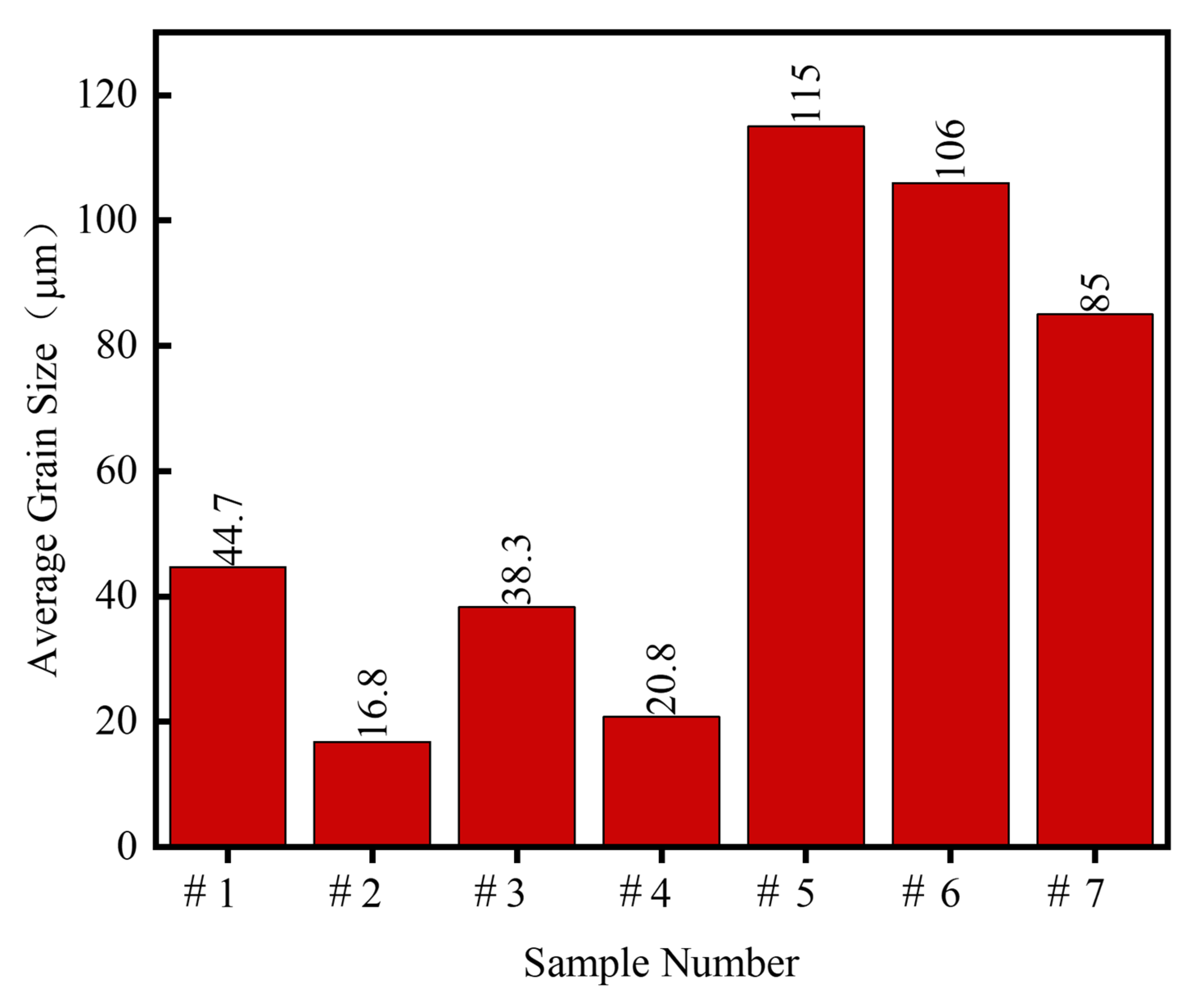
With the increase in Al content, the grains in the coatings are gradually refined. The added nano-Al2O3 exacerbates the coatings elemental segregation and the second-phase precipitation;
(2)
The addition of nano-Al2O3 results in second-phase reinforcement and grain refinement can improve the mechanical properties of FeCrAlY coatings, especially in terms of hardness;
(3)
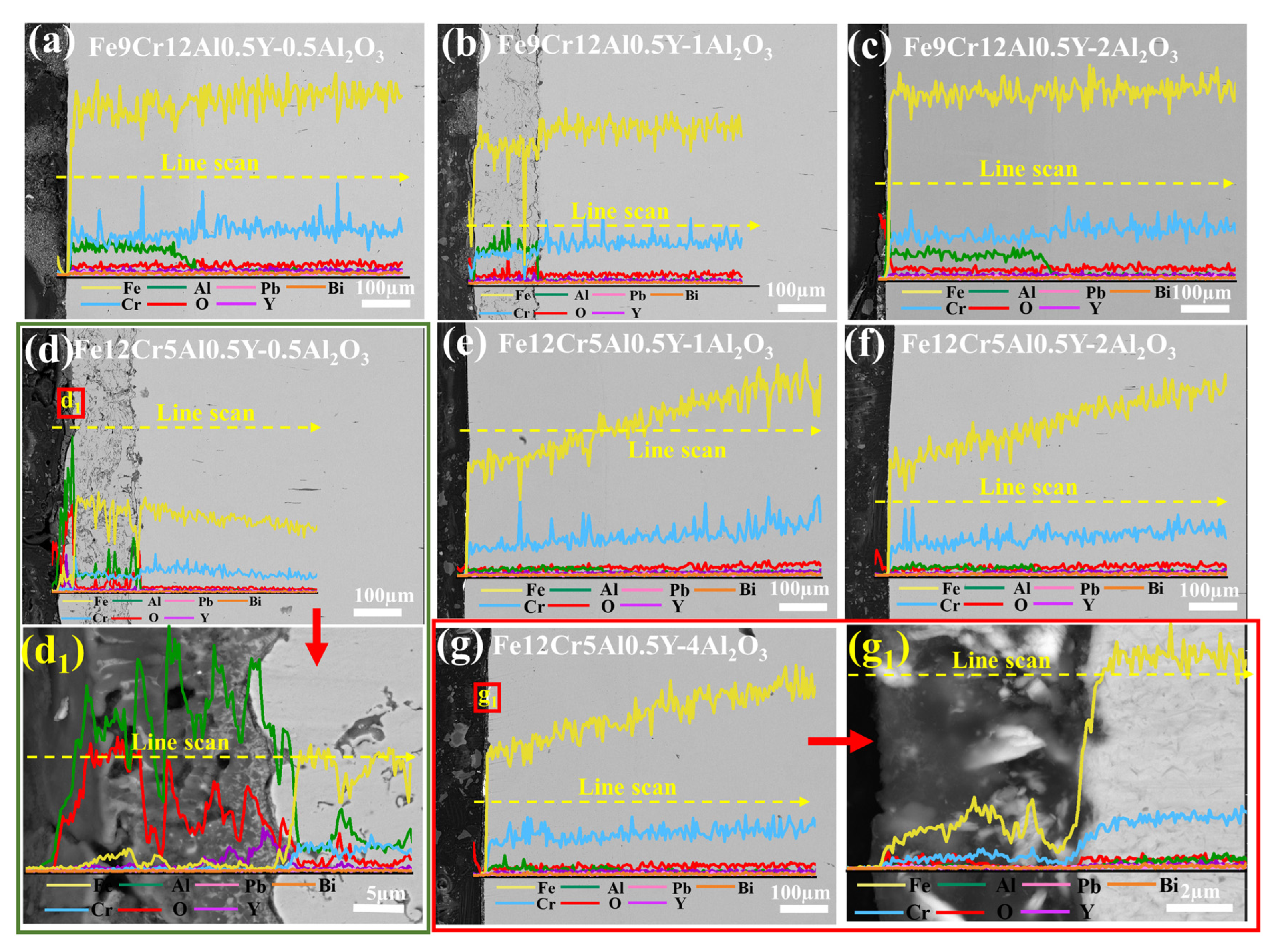
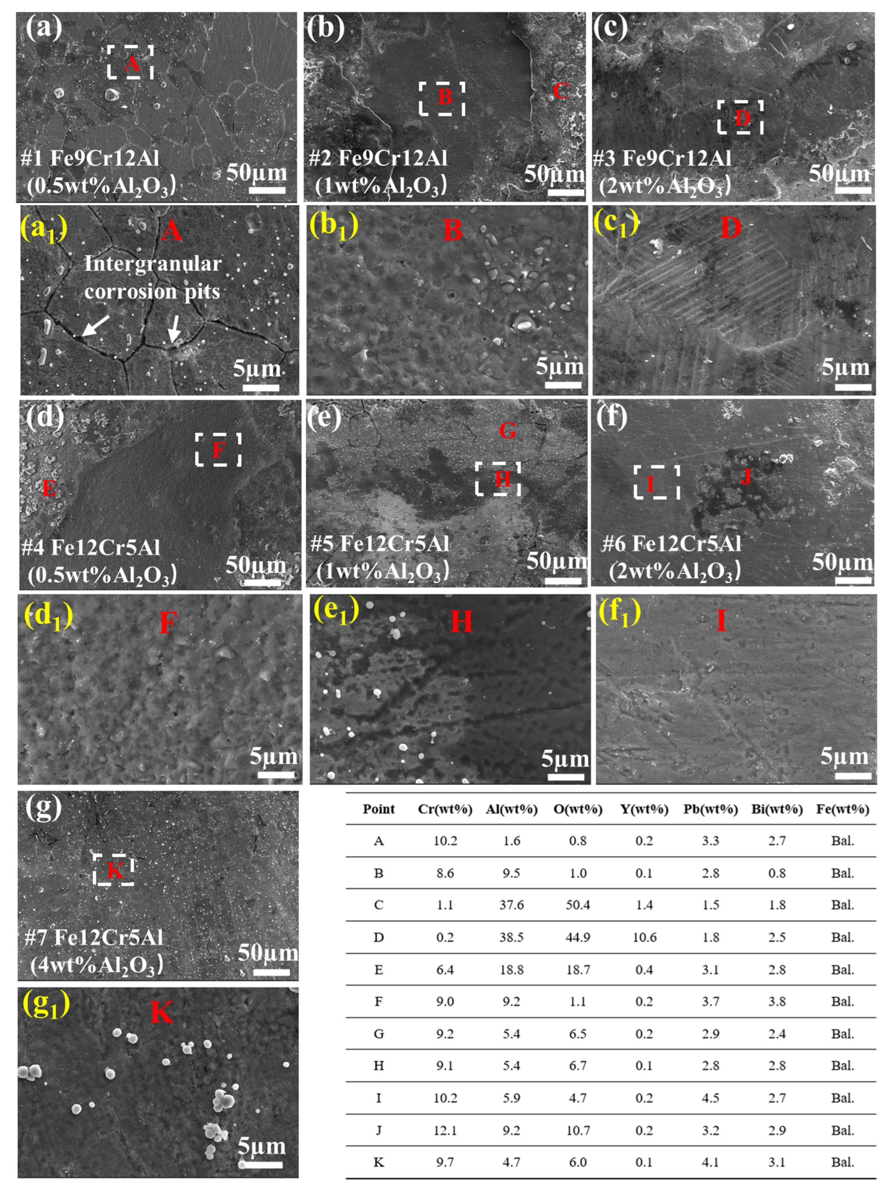
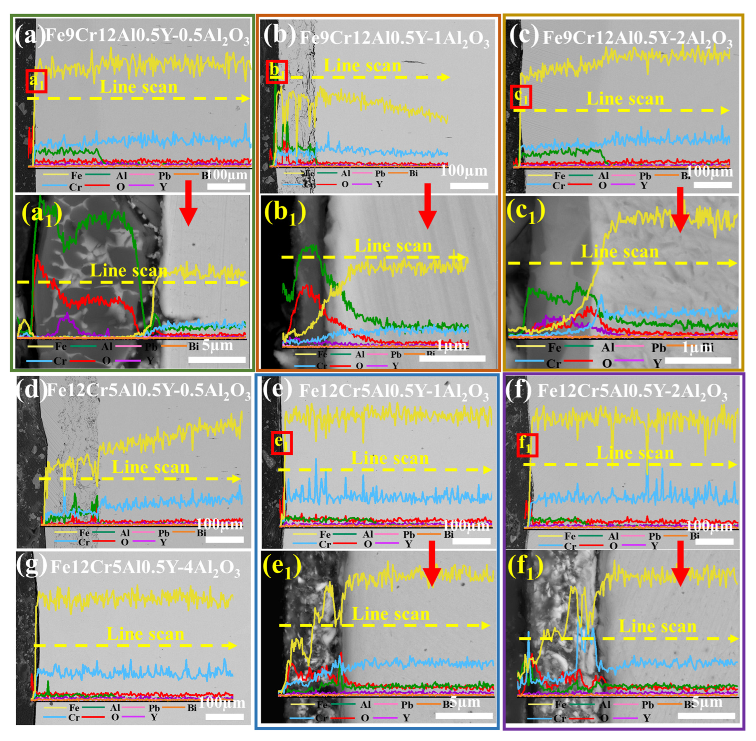
Intergranular corrosion is observed after LBE corrosion tests. This phenomenon, which is sensitive to the corrosion temperature, is closely related to the Cr and Al content of the coating.

Supplementary Materials

The following supporting information can be downloaded at: https://www.mdpi.com/article/10.3390/coatings14040393/s1, Figure S1 (a–d): Band Contrast images of Fe9Cr12Al0.5Y-Al2O3 coatings with different addition of 0.5 wt%, 1 wt% and 2 wt% Al2O3 and Fe12Cr5Al0.5Y-Al2O3 coatings with addition of 0.5 wt% Al2O3 (#1-#4); (a1–d1): phase diagrams corresponding to (a–d). Figure S2: Cross-sectional SEM morphology patterns of the FeCrAlY-Al2O3 coatings corroded at 500 °C for 1000 h in static LBE: (a–c) Fe9Cr12Al0.5Y with different nano-Al2O3 addition; (d–g) Fe12Cr5Al0.5Y with different nano-Al2O3 addition. Figure S3: Cross-sectional SEM morphology patterns of the FeCrAlY-Al2O3 coatings corroded at 550 °C for 1000 h in static LBE: (a–c) Fe9Cr12Al0.5Y with different nano-Al2O3 addition; (d–g) Fe12Cr5Al0.5Y with different nano-Al2O3 addition. Figure S4: Cross-sectional SEM morphology patterns of the FeCrAlY-Al2O3 coatings corroded at 600 °C for 1000 h in static LBE: (a–c) Fe9Cr12Al0.5Y with different nano-Al2O3 addition.; (d–g) Fe12Cr5Al0.5Y with different nano-Al2O3 addition.

Author Contributions

Conceptualization, J.Y. (Jian Yang), Y.Z. (Yuxin Zhong) and J.Y. (Jijun Yang); Methodology, W.Z. and C.Z.; Formal analysis, Q.L.; Investigation, H.L. and J.D.; Data curation, Q.L.; Writing—original draft, Q.L.; Writing—review & editing, Q.L. and Y.Z. (Yilong Zhong); Visualization, S.Z.; Supervision, J.Y. (Jijun Yang); Project administration, M.Z. and X.Q.; Funding acquisition, J.Y. (Jijun Yang). All authors have read and agreed to the published version of the manuscript.

Funding

This research was funded by the Nuclear Power Institute of China.

Institutional Review Board Statement

Not applicable.

Informed Consent Statement

Not applicable.

Data Availability Statement

Data are contained within the article and Supplementary Materials.

Conflicts of Interest

The authors declare no conflict of interest.

References

  1. Abram, T.; Ion, S. Generation-IV nuclear power: A review of the state of the science. Energy Policy 2008, 36, 4323–4330. [Google Scholar] [CrossRef]
  2. Lorusso, P.; Bassini, S.; Del Nevo, A.; Di Piazza, I.; Giannetti, F.; Tarantino, M.; Utili, M. GEN-IV LFR development: Status & perspectives. Prog. Nucl. Energy 2018, 105, 318–331. [Google Scholar] [CrossRef]
  3. Grasso, G.; Petrovich, C.; Mattioli, D.; Artioli, C.; Sciora, P.; Gugiu, D.; Bandini, G.; Bubelis, E.; Mikityuk, K. The core design of ALFRED, a demonstrator for the European lead-cooled reactors. Nucl. Eng. Des. 2014, 278, 287–301. [Google Scholar] [CrossRef]
  4. Alemberti, A.; Smirnov, V.; Smith, C.F.; Takahashi, M. Overview of lead-cooled fast reactor activities. Prog. Nucl. Energy 2014, 77, 300–307. [Google Scholar] [CrossRef]
  5. Weisenburger, A.; Schroer, C.; Jianu, A.; Heinzel, A.; Konys, J.; Steiner, H.; Müller, G.; Fazio, C.; Gessi, A.; Babayan, S.; et al. Long term corrosion on T91 and AISI1 316L steel in flowing lead alloy and corrosion protection barrier development: Experiments and models. J. Nucl. Mater. 2011, 415, 260–269. [Google Scholar] [CrossRef]
  6. Chen, G.; Lei, Y.; Zhu, Q.; Ju, N.; Li, T.; Wang, D. Corrosion behavior of CLAM steel weld bead in flowing Pb-Bi at 550 °C. J. Nucl. Mater. 2019, 515, 187–198. [Google Scholar] [CrossRef]
  7. Gong, X.; Short, M.P.; Auger, T.; Charalampopoulou, E.; Lambrinou, K. Environmental degradation of structural materials in liquid lead- and lead-bismuth eutectic-cooled reactors. Prog. Mater. Sci. 2022, 126, 100920. [Google Scholar] [CrossRef]
  8. Zhang, J.; Li, N. Review of the studies on fundamental issues in LBE corrosion. J. Nucl. Mater. 2008, 373, 351–377. [Google Scholar] [CrossRef]
  9. Martín-Muñoz, F.J.; Soler-Crespo, L.; Gómez-Briceño, D. Corrosion behaviour of martensitic and austenitic steels in flowing lead–bismuth eutectic. J. Nucl. Mater. 2011, 416, 87–93. [Google Scholar] [CrossRef]
  10. Zinkle, S.J.; Was, G.S. Materials challenges in nuclear energy. Acta Mater. 2013, 61, 735–758. [Google Scholar] [CrossRef]
  11. Martinelli, L.; Jean-Louis, C.; Fanny, B.-C. Oxidation of steels in liquid lead bismuth: Oxygen control to achieve efficient corrosion protection. Nucl. Eng. Des. 2011, 241, 1288–1294. [Google Scholar] [CrossRef]
  12. Ma, H.; Gong, X.; Zhu, J.; Chen, H.; Li, J.; Liu, Y.; Ren, Q.; Zhang, F.; Pang, Z. Liquid metal embrittlement susceptibility of an oxide-dispersion strengthened FeCrAl alloy in contact with liquid lead-bismuth eutectic at 350 °C. Corros. Sci. 2022, 207, 110603. [Google Scholar] [CrossRef]
  13. Tan, L.; Machut, M.T.; Sridharan, K.; Allen, T.R. Corrosion behavior of a ferritic/martensitic steel HCM12A exposed to harsh environments. J. Nucl. Mater. 2007, 371, 161–170. [Google Scholar] [CrossRef]
  14. Kimura, A.; Kasada, R.; Iwata, N.; Kishimoto, H.; Zhang, C.H.; Isselin, J.; Dou, P.; Lee, J.H.; Muthukumar, N.; Okuda, T.; et al. Development of Al added high-Cr ODS steels for fuel cladding of next generation nuclear systems. J. Nucl. Mater. 2011, 417, 176–179. [Google Scholar] [CrossRef]
  15. Ukai, S.; Ohtsuka, S.; Kaito, T.; de Carlan, Y.; Ribis, J.; Malaplate, J. Oxide dispersion-strengthened/ferrite-martensite steels as core materials for Generation IV nuclear reactors. In Structural Materials for Generation IV Nuclear Reactors; Woodhead Publishing: Cambridge, UK, 2017; pp. 357–414. [Google Scholar]
  16. Serag, E.; Caers, B.; Schuurmans, P.; Lucas, S.; Haye, E. Challenges and coating solutions for wear and corrosion inside Lead Bismuth Eutectic: A review. Surf. Coat. Technol. 2022, 441, 128542. [Google Scholar] [CrossRef]
  17. Ferré, F.G.; Mairov, A.; Iadicicco, D.; Vanazzi, M.; Bassini, S.; Utili, M.; Tarantino, M.; Bragaglia, M.; Lamastra, F.R.; Nanni, F.; et al. Corrosion and radiation resistant nanoceramic coatings for lead fast reactors. Corros. Sci. 2017, 124, 80–92. [Google Scholar] [CrossRef]
  18. Utili, M.; Agostini, M.; Coccoluto, G.; Lorenzini, E. Ti3SiC2 as a candidate material for lead cooled fast reactor. Nucl. Eng. Des. 2011, 241, 1295–1300. [Google Scholar] [CrossRef]
  19. Glasbrenner, H.; Gröschel, F. Exposure of pre-stressed T91 coated with TiN, CrN and DLC to Pb–55.5Bi. J. Nucl. Mater. 2006, 356, 213–221. [Google Scholar] [CrossRef]
  20. Heinzel, A.; Weisenburger, A.; Müller, G. Long-term corrosion tests of Ti3SiC2 and Ti2AlC in oxygen containing LBE at temperatures up to 700 °C. J. Nucl. Mater. 2016, 482, 114–123. [Google Scholar] [CrossRef]
  21. Wu, Z.Y.; Zhao, X.; Liu, Y.; Cai, Y.; Li, J.Y.; Chen, H.; Wan, Q.; Yang, D.; Tan, J.; Liu, H.D.; et al. Lead-bismuth eutectic (LBE) corrosion behavior of AlTiN coatings at 550 and 600 °C. J. Nucl. Mater. 2020, 539, 152280. [Google Scholar] [CrossRef]
  22. García Ferré, F.; Ormellese, M.; Di Fonzo, F.; Beghi, M.G. Advanced Al2O3 coatings for high temperature operation of steels in heavy liquid metals: A preliminary study. Corros. Sci. 2013, 77, 375–378. [Google Scholar] [CrossRef]
  23. Wan, Q.; Wu, Z.Y.; Liu, Y.; Yang, B.; Liu, H.D.; Ren, F.; Wang, P.; Xiao, Y.Y.; Zhang, J.; Zhang, G.D. Lead-bismuth eutectic (LBE) corrosion mechanism of nano-amorphous composite TiSiN coatings synthesized by cathodic arc ion plating. Corros. Sci. 2021, 183, 109264. [Google Scholar] [CrossRef]
  24. Zhong, Y.; Zhang, W.; Chen, Q.; Yang, J.; Zhu, C.; Li, Q.; Yang, J.; Liu, N.; Yang, J. Effect of LBE corrosion on microstructure of amorphous Al2O3 coating by magnetron sputtering. Surf. Coat. Technol. 2022, 443, 128598. [Google Scholar] [CrossRef]
  25. Lapauw, T.; Tunca, B.; Joris, J.; Jianu, A.; Fetzer, R.; Weisenburger, A.; Vleugels, J.; Lambrinou, K. Interaction of Mn+1AXn phases with oxygen-poor, static and fast-flowing liquid lead-bismuth eutectic. J. Nucl. Mater. 2019, 520, 258–272. [Google Scholar] [CrossRef]
  26. Zhong, Y.; Zhu, C.; Zhang, W.; Yang, J.; Deng, J.; Li, Q.; Liu, H.; Zhou, Y.; Yue, H.; Qiu, X.; et al. Exploring the application potential of FexAl/Al2O3 coatings for lead-cooled fast reactors. J. Nucl. Mater. 2024, 588, 154807. [Google Scholar] [CrossRef]
  27. Zhong, Y.; Li, Q.; Zhao, Y.; Zhou, Y.; Zhang, W.; Yang, J.; Zhu, C.; Deng, J.; Chen, Q.; Zhao, S.; et al. Irradiation effects on microstructure, mechanical properties, and lead-bismuth eutectic corrosion resistance of alumina coating. J. Mater. Res. Technol. 2023, 25, 2014–2028. [Google Scholar] [CrossRef]
  28. Fetzer, R.; Weisenburger, A.; Jianu, A.; Müller, G. Oxide scale formation of modified FeCrAl coatings exposed to liquid lead. Corros. Sci. 2012, 55, 213–218. [Google Scholar] [CrossRef]
  29. Weisenburger, A.; Heinzel, A.; Müller, G.; Muscher, H.; Rousanov, A. T91 cladding tubes with and without modified FeCrAlY coatings exposed in LBE at different flow, stress and temperature conditions. J. Nucl. Mater. 2008, 376, 274–281. [Google Scholar] [CrossRef]
  30. Kurata, Y.; Yokota, H.; Suzuki, T. Development of aluminum-alloy coating on type 316SS for nuclear systems using liquid lead–bismuth. J. Nucl. Mater. 2012, 424, 237–246. [Google Scholar] [CrossRef]
  31. Dai, Y.; Boutellier, V.; Gavillet, D.; Glasbrenner, H.; Weisenburger, A.; Wagner, W. FeCrAlY and TiN coatings on T91 steel after irradiation with 72MeV protons in flowing LBE. J. Nucl. Mater. 2012, 431, 66–76. [Google Scholar] [CrossRef]
  32. Yin, X.; Wang, H.; Xiao, J.; Sun, Y.; Zhao, K.; Wu, J.; Sui, X.; Wang, H.; Chen, Y. A high-entropy alloy nitride protective coating for fuel cladding in high temperature lead-bismuth eutectic alloy. J. Nucl. Mater. 2022, 568, 153888. [Google Scholar] [CrossRef]
  33. Deng, J.; Yang, J.; Lv, L.; Zhang, W.; Chen, Q.; Zhou, M.; Zhu, C.; Liu, N.; Yang, J. Corrosion behavior of refractory TiNbZrMoV high-entropy alloy coating in static lead-bismuth eutectic alloy: A novel design strategy of LBE corrosion-resistant coating? Surf. Coat. Technol. 2022, 448, 128884. [Google Scholar] [CrossRef]
  34. Zhang, W.; Zhong, Y.; Qiu, X.; Li, Q.; Yue, H.; Zhou, Y.; Deng, J.; Yang, J.; Liu, H.; Li, Q.; et al. Screening of the FeCrAl LBE corrosion-resistant coatings: The effect of Cr and Al contents. Surf. Coat. Technol. 2023, 462, 129477. [Google Scholar] [CrossRef]
  35. Short, M.P.; Ballinger, R.G.; Hänninen, H.E. Corrosion resistance of alloys F91 and Fe–12Cr–2Si in lead–bismuth eutectic up to 715 °C. J. Nucl. Mater. 2013, 434, 259–281. [Google Scholar] [CrossRef]
  36. Hussain, T.; Simms, N.J.; Nicholls, J.R.; Oakey, J.E. Fireside corrosion degradation of HVOF thermal sprayed FeCrAl coating at 700–800 °C. Surf. Coat. Technol. 2015, 268, 165–172. [Google Scholar] [CrossRef]
  37. Wang, H.; Liang, G.; Meng, C.; An, X.; Wang, Y.; He, X. A comparative study on the corrosion performance of four FeCrAl alloys with different Cr contents in contact with oxygen-saturated LBE. J. Mater. Res. Technol. 2023, 23, 3492–3504. [Google Scholar] [CrossRef]
  38. Edmondson, P.D.; Briggs, S.A.; Yamamoto, Y.; Howard, R.H.; Sridharan, K.; Terrani, K.A.; Field, K.G. Irradiation-enhanced α’ precipitation in model FeCrAl alloys. Scr. Mater. 2016, 116, 112–116. [Google Scholar] [CrossRef]
  39. Field, K.G.; Briggs, S.A.; Sridharan, K.; Howard, R.H.; Yamamoto, Y. Mechanical properties of neutron-irradiated model and commercial FeCrAl alloys. J. Nucl. Mater. 2017, 489, 118–128. [Google Scholar] [CrossRef]
  40. Rajput, A.; Ramkumar, J.; Mondal, K. Effect of addition of strong oxidizer and temperature on the cavitation erosion resistance of different microstructures made from a high carbon steel. Wear 2022, 494–495, 204245. [Google Scholar] [CrossRef]
  41. Wang, Q.; Li, Z.; Pang, S.; Li, X.; Dong, C.; Liaw, P.K. Coherent Precipitation and Strengthening in Compositionally Complex Alloys: A Review. Entropy 2018, 20, 878. [Google Scholar] [CrossRef]
  42. Müller, G.; Schumacher, G.; Strauß, D. Oxide scale growth on MCrAlY coatings after pulsed electron beam treatment. Surf. Coat. Technol. 1998, 108–109, 43–47. [Google Scholar] [CrossRef]
  43. Zhu, Z.; Li, J.; Peng, Y.; Shen, G. In-situ synthesized novel eyeball-like Al2O3/TiC composite ceramics reinforced Fe-based alloy coating produced by laser cladding. Surf. Coat. Technol. 2020, 391, 125671. [Google Scholar] [CrossRef]
  44. Yue, J.; Liu, X.; Sui, Y.; Liu, C.; Sun, X.; Chen, W. Combined effect of Y2O3 nanoparticles and Si second-phase oxide on microstructure and wear resistance of plasma-clad steel coating. Surf. Coat. Technol. 2020, 403, 126348. [Google Scholar] [CrossRef]
  45. Zhou, L.; Zhou, W.; Su, J.; Luo, F.; Zhu, D.; Dong, Y. Plasma sprayed Al2O3/FeCrAl composite coatings for electromagnetic wave absorption application. Appl. Surf. Sci. 2012, 258, 2691–2696. [Google Scholar] [CrossRef]
  46. Yang, L.; Li, Z.; Zhang, Y.; Wei, S.; Wang, Y.; Kang, Y. In-situ TiC-Al3Ti reinforced Al-Mg composites with Y2O3 addition formed by laser cladding on AZ91D. Surf. Coat. Technol. 2020, 383, 125249. [Google Scholar] [CrossRef]
  47. Shen, J.; Chai, L.; Wang, H.; Wang, C.; Yuan, Q.; Guo, N.; Xiao, J.; Yin, X. Surface microstructures and properties of oxide-reinforced FeCrAl matrix composite coatings prepared by laser cladding on a ferritic-martensitic steel. J. Nucl. Mater. 2023, 578, 154345. [Google Scholar] [CrossRef]
  48. Ghosh, A.; Wu, W.; Sahu, B.P.; Wang, J.; Misra, A. Enabling plastic co-deformation of disparate phases in a laser rapid solidified Sr-modified Al–Si eutectic through partial-dislocation-mediated-plasticity in Si. Mater. Sci. Eng. A 2023, 885, 145648. [Google Scholar] [CrossRef]
  49. Hong, J.; Choi, H.; Lee, S.; Kim, J.K.; Koo, Y.m. Effect of Al content on magnetic properties of Fe-Al Non-oriented electrical steel. J. Magn. Magn. Mater. 2017, 439, 343–348. [Google Scholar] [CrossRef]
  50. Straumal, B.B.; Korneva, A.; Kuzmin, A.; Lopez, G.A.; Rabkin, E.; Straumal, A.B.; Gerstein, G.; Gornakova, A.S. The grain boundary wetting phenomena in the ti-containing high-entropy alloys: A review. Metals 2021, 11, 1881. [Google Scholar] [CrossRef]
  51. London, A.J.; Santra, S.; Amirthapandian, S.; Panigrahi, B.K.; Sarguna, R.M.; Balaji, S.; Vijay, R.; Sundar, C.S.; Lozano-Perez, S.; Grovenor, C.R.M. Effect of Ti and Cr on dispersion, structure and composition of oxide nano-particles in model ODS alloys. Acta Mater. 2015, 97, 223–233. [Google Scholar] [CrossRef]
  52. Karak, S.K.; Chudoba, T.; Witczak, Z.; Lojkowski, W.; Manna, I. Development of ultra high strength nano-Y2O3 dispersed ferritic steel by mechanical alloying and hot isostatic pressing. Mater. Sci. Eng. A 2011, 528, 7475–7483. [Google Scholar] [CrossRef]
  53. Jiang, W.; Lu, J.; Guan, H.; Wang, M.; Cheng, X.; Liu, L.; Liu, X.; Wang, J.; Zhang, Y.; Zhang, Z.; et al. Study of pre-precipitated δ phase promoting deformation twinning and recrystallization behavior of Inconel 718 superalloy during hot compression. Mater. Des. 2023, 226, 111693. [Google Scholar] [CrossRef]
  54. Zhang, Z.; Jiang, W.; guan, F.; Li, G.; Fan, Z. Interface formation and strengthening mechanisms of Al/Mg bimetallic composite via compound casting with rare earth Ce introduction. Mater. Sci. Eng. A 2022, 854, 143830. [Google Scholar] [CrossRef]
  55. Zhao, M.; Wu, H.; Lu, J.; Sun, G.; Du, L. Effect of grain size on mechanical property and corrosion behavior of a metastable austenitic stainless steel. Mater. Charact. 2022, 194, 112360. [Google Scholar] [CrossRef]
  56. Zhang, Z.; Yang, F.; Zhang, H.; Zhang, T.; Wang, H. Microstructure and element distribution of laser cladding TiCx-reinforced CrTi4-based composite coating with CeO2/Ce2O3. Mater. Lett. 2021, 283, 128772. [Google Scholar] [CrossRef]
  57. Gan, J.; Gong, Q.; Jiang, Y.; Chen, H.; Huang, Y.; Du, K.; Li, Y.; Zhao, M.; Lin, F.; Zhuang, D. Microstructure and high-temperature mechanical properties of second-phase enhanced Mo-La2O3-ZrC alloys post-treated by cross rolling. J. Alloys Compd. 2019, 796, 167–175. [Google Scholar] [CrossRef]
  58. Pint, B.A. Experimental observations in support of the dynamic-segregation theory to explain the reactive-element effect. Oxid. Met. 1996, 45, 1–37. [Google Scholar] [CrossRef]
  59. Pint, B.A. Optimization of reactive-element additions to improve oxidation performance of alumina-forming alloys. J. Am. Ceram. Soc. 2002, 86, 686–695. [Google Scholar]
  60. He, Y.; Liu, J.; Qiu, S.; Deng, Z.; Yang, Y.; McLean, A. Microstructure and high temperature mechanical properties of as-cast FeCrAl alloys. Mater. Sci. Eng. A 2018, 726, 56–63. [Google Scholar] [CrossRef]
  61. Dular, M.; Delgosha, O.C.; Petkovšek, M. Observations of cavitation erosion pit formation. Ultrason. Sonochem. 2013, 20, 1113–1120. [Google Scholar] [CrossRef]
  62. Gong, X.; Marmy, P.; Yin, Y. The role of oxide films in preventing liquid metal embrittlement of T91 steel exposed to liquid lead-bismuth eutectic. J. Nucl. Mater. 2018, 509, 401–407. [Google Scholar] [CrossRef]
  63. Popovic, M.P.; Chen, K.; Shen, H.; Stan, C.V.; Olmsted, D.L.; Tamura, N.; Asta, M.; Abad, M.D.; Hosemann, P. A study of deformation and strain induced in bulk by the oxide layers formation on a Fe-Cr-Al alloy in high-temperature liquid Pb-Bi eutectic. Acta Mater. 2018, 151, 301–309. [Google Scholar] [CrossRef]
  64. Weisenburger, A.; Jianu, A.; Doyle, S.; Bruns, M.; Fetzer, R.; Heinzel, A.; DelGiacco, M.; An, W.; Müller, G. Oxide scales formed on Fe–Cr–Al-based model alloys exposed to oxygen containing molten lead. J. Nucl. Mater. 2013, 437, 282–292. [Google Scholar] [CrossRef]
  65. Zhang, Z.G.; Gesmundo, F.; Hou, P.Y.; Niu, Y. Criteria for the formation of protective Al2O3 scales on Fe–Al and Fe–Cr–Al alloys. Corros. Sci. 2006, 48, 741–765. [Google Scholar] [CrossRef]
  66. Lim, J.; Nam, H.O.; Hwang, I.S.; Kim, J.H. A study of early corrosion behaviors of FeCrAl alloys in liquid lead–bismuth eutectic environments. J. Nucl. Mater. 2010, 407, 205–210. [Google Scholar] [CrossRef]
  67. Engelko, V.; Mueller, G.; Rusanov, A.; Markov, V.; Tkachenko, K.; Weisenburger, A.; Kashtanov, A.; Chikiryaka, A.; Jianu, A. Surface modification/alloying using intense pulsed electron beam as a tool for improving the corrosion resistance of steels exposed to heavy liquid metals. J. Nucl. Mater. 2011, 415, 270–275. [Google Scholar] [CrossRef]
  68. Fazio, C.; Balbaud, F. 2—Corrosion phenomena induced by liquid metals in Generation IV reactors. In Structural Materials for Generation IV Nuclear Reactors; Yvon, P., Ed.; Woodhead Publishing: Cambridge, UK, 2017; pp. 23–74. [Google Scholar] [CrossRef]
  69. Xu, Z.; Song, L.; Zhao, Y.; Liu, S. The formation mechanism and effect of amorphous SiO2 on the corrosion behaviour of Fe-Cr-Si ODS alloy in LBE at 550 °C. Corros. Sci. 2021, 190, 109634. [Google Scholar] [CrossRef]
Figure 1. Schematic diagram of the static liquid LBE corrosion test.
Coatings 14 00393 g001
Figure 2. Typical SEM cross-sectional images of Fe12Cr5Al0.5Y (1 wt% Al2O3) coating after plasma spraying (a) and laser remelting (b). The small pictures are the zoomed in red areas.
Coatings 14 00393 g002
Figure 3. The surface morphology and the corresponding point-scan component results of the prepared FeCrAlY-Al2O3 coatings: (ac) Fe9Cr12Al0.5Y with different nano-Al2O3 additions; (dg) Fe12Cr5Al0.5Y with different nano-Al2O3 additions. (a1g1) are partial enlargements of the white dashed area in plots (ag), respectively.
Coatings 14 00393 g003
Figure 4. Cross-sectional morphology and corresponding point-scan and EDS line-scan results of the prepared FeCrAlY-Al2O3 coatings: (ac) Fe9Cr12Al0.5Y with different nano-Al2O3 additions; (dg) Fe12Cr5Al0.5Y with different nano-Al2O3 additions.
Coatings 14 00393 g004
Figure 5. (a) XRD patterns of FeCrAlY-Al2O3 coatings prepared by plasma spraying. (b) XRD patterns of FeCrAlY-Al2O3 coatings modified by laser remelting after plasma spraying. (c) Magnified XRD patterns of the circled diffraction peak region in (b).
Coatings 14 00393 g005
Figure 6. (ac): Band contrast images of Fe12Cr5Al0.5Y-Al2O3 coatings with different additions of 1 wt%, 2 wt%, and 4 wt% Al2O3 (#5–#7); (a1c1): phase diagrams corresponding to (ac).
Coatings 14 00393 g006
Figure 7. Average grain size of FeCrAlY-Al2O3 coatings modified by laser remelting after plasma spraying.
Coatings 14 00393 g007
Figure 8. Effect of coatings composition content on the mechanical properties of the prepared FeCrAlY-Al2O3 coatings: (a) representative nanoindentation displacement–load curves; (b) nanohardness H variations along depth; (c) elastic modulus E variations along depth; (d) the ratio of H/E and H3/E2 varied with the nano-Al2O3 addition.
Coatings 14 00393 g008
Figure 9. Surface morphology and the corresponding point-scan component results of the FeCrAlY-Al2O3 coatings corroded at 500 °C for 1000 h in static LBE: (ac) Fe9Cr12Al0.5Y with different nano-Al2O3 additions; (dg) Fe12Cr5Al0.5Y with different nano-Al2O3 additions. (a1g1) are partial enlargements of the white dashed area in plots (ag), respectively.
Coatings 14 00393 g009
Figure 10. EDS line-scan of the FeCrAlY-Al2O3 coatings corroded at 500 °C for 1000 h in static LBE: (ac) Fe9Cr12Al0.5Y with different nano-Al2O3 additions; (dg) Fe12Cr5Al0.5Y with different nano-Al2O3 additions. (c1,g1) are partial enlargements of the red boxed area in (c,g), respectively.
Coatings 14 00393 g010
Figure 11. Surface morphology and the corresponding point-scan component results of the FeCrAlY-Al2O3 coatings corroded at 550 °C for 1000 h in static LBE: (ac) Fe9Cr12Al0.5Y with different nano-Al2O3 additions; (dg) Fe12Cr5Al0.5Y with different nano-Al2O3 additions. (a1g1) are partial enlargements of the white dashed area in plots (ag), respectively.
Coatings 14 00393 g011
Figure 12. EDS line-scan of the FeCrAlY-Al2O3 coatings corroded at 550 °C for 1000 h in static LBE: (ac) Fe9Cr12Al0.5Y with different nano-Al2O3 additions; (dg) Fe12Cr5Al0.5Y with different nano-Al2O3 additions. (d1,g1) are partial enlargements of the red boxed area in (d,g), respectively.
Coatings 14 00393 g012
Figure 13. Surface morphology and the corresponding point-scan component results of the FeCrAlY-Al2O3 coatings corroded at 600 °C for 1000 h in static LBE: (ac) Fe9Cr12Al0.5Y with different nano-Al2O3 additions; (dg) Fe12Cr5Al0.5Y with different nano-Al2O3 additions. (a1g1) are partial enlargements of the white dashed area in plots (ag), respectively.
Coatings 14 00393 g013
Figure 14. EDS line-scan of the FeCrAlY-Al2O3 coatings corroded at 600 °C for 1000 h in static LBE: (ac) Fe9Cr12Al0.5Y with different nano-Al2O3 additions; (dg) Fe12Cr5Al0.5Y with different nano-Al2O3 additions. (a1c1,e1,f1) are partial enlargements of the red boxed area in (ac,e,f), respectively.
Coatings 14 00393 g014
Figure 15. The dependence of thickness of corrosion oxides and intergranular corrosion of FeCrAlY nanoceramic composite coatings in LBE at different temperatures with different nano-Al2O3 additions: (a) diagram of oxide scale thickness in liquid LBE. The gray area represents the generation of a visible Al-rich oxide layer; white area represents the generation of the extremely thin oxide layer; different icons and colors represent different corrosion temperatures and FeCrAlY compositions. (b) Diagram of degree of intergranular corrosion in liquid LBE. Shades of gray indicate the degree of intergranular corrosion; different icons and colors represent different corrosion temperatures and FeCrAlY compositions; the degree of intergranular corrosion is artificially assessed by the depth of the corrosion pits.
Coatings 14 00393 g015
Table 1. The chemical composition of the F/M steel (wt%).
ElementsCrWVMnTaFe
wt%11.61.50.131.10.15Bal.
Table 2. The plasma spraying parameters of the coating fabrication.
Spraying Distance
(mm)
Electric Current
(A)
Voltage (V)Main Gas Flow
(L/min)
Second Gas Flow
(L/min)
Powder Feeding Speed
(g/min)
1306007045820
Disclaimer/Publisher’s Note: The statements, opinions and data contained in all publications are solely those of the individual author(s) and contributor(s) and not of MDPI and/or the editor(s). MDPI and/or the editor(s) disclaim responsibility for any injury to people or property resulting from any ideas, methods, instructions or products referred to in the content.

