Abstract
A porous anti-reflective coating (P-ARC) with average transmittance in the visible range of 97.9% was fabricated through the sol-gel method, followed by calcination at a relatively low temperature (220 °C) using the porogen of Laureth-5 carboxylic acid via a one-step approach. The results demonstrated the coating had an absolute value that was 7.5% higher than that of bare glass (92%). The prepared porous anti-reflective coating had a refractive index as low as 1.21. The coating remained undamaged during 3M tape stripping tests while maintaining excellent light transmittance. This work presents a film that has good thermal stability, chemical stability, and mechanical stability.
1. Introduction
In recent years, the development of high-performance anti-reflective coatings has been a major focus of research and has led to significant advances in a wide range of fields, including optics, materials, and engineering [1,2,3]. Much progress, including new materials and fabrication techniques, has been achieved [4,5,6]. Playing an important role in optics, ARCs can reduce the amount of light reflected from the surface of a material, thus improving the efficiency and performance of optical systems [7]. ARCs are widely employed in lenses, solar panels, and various other optical devices to enhance their transparency and minimize glare [8,9,10]. The fundamental principle of ARCs is that the reflection of light at the interface between two media with different refractive indices is reduced [11]. This can be achieved via the application of a thin film possessing a low refractive index onto a substrate characterized by a high refractive index. The thickness and refractive index of the coating can be tailored to minimize the reflection at a specific wavelength or over a broad range of wavelengths [12,13].
The most commonly used methods for preparing ARCs are chemical vapor deposition (CVD) [14], physical vapor deposition (PVD) [15], etching technology [16], and sol-gel synthesis [17]. These methods can effectively reduce the reflection of light on the surface of the material, improve the transparency of the coating, and enhance the overall performance of optical devices. Among a variety of different coating processes, the sol-gel method has many potential advantages, such as adjustable refractive index materials, a simple process, a low cost, and suitability for special-shaped structures [18].
Compared with regular ARCs, it is considered that porous ARCs exhibit many advantages [19,20]. Porous anti-reflection films have a larger surface area and pore volume, which results in a decrease in the refractive index and occurrence of light interference, thereby enabling them to have higher transmittance and less reflected light. Therefore, porous silica-based materials have been extensively studied due to their unique properties and potential applications [21,22]. The design of the pore network in these materials is a critical factor in controlling their properties, such as porosity, surface area, and connectivity. For instance, Boudot et al. developed a method for producing mesoporous silica-based films with precise control over both pore size and porous fraction. This is achieved by combining the sol-gel approach with an alkali ion post-treatment, which allows for the reconstruction of the porous mesostructure of surfactant-templated silica films through alkali metal ion diffusion into the inorganic matrix at 450 °C. A maximum amount of transmittance, approximately 95% at approximately 530 nm, can be achieved [23]. In another work, an acid-catalyzed sol-gel technique was optimized to fabricate SiO2, which was then deposited on glass for sintering in a conventional furnace at temperatures ranging from 350 to 550 °C for 1 h. The prepared ARCs exhibited broadband anti-reflection properties across the spectral response range of multijunction solar cells. By fine-tuning the process in the visible light range, the coating achieved 6% anti-reflection [24]. In addition, researchers are also interested in fabricating materials with hierarchical porosity, which can optimize the preparation processes of porous ARCs [25,26]. However, most of the preparation processes of porous ARCs have to eliminate porogens at high temperatures or through centrifugal washing using organic solvents, thus excessively increasing energy consumption or environmental pollution.
In this work, we report a facile strategy to fabricate a porous AR coating using a one-step approach. We prepared a coating with high light transmittance and a low refractive index. Laureth-5 carboxylic acid (LCA) was introduced for the first time to allow the pores to disperse more evenly. The coating only needed to endure a low temperature (220 °C) for a duration of half an hour during the heat treatment process. LCA is one of the raw materials involved in the reaction, and it is a surfactant commonly utilized in daily life and found in various personal care products. It is non-toxic and environmentally friendly. This work presents an efficient and cost-effective method for preparing a porous anti-reflection coating and provides a detailed study of its optical properties, such as transmittance, refractive index, and mechanical performance.
2. Experimental Section
2.1. Materials
TEOS (≥99.99%) was obtained from Macklin Company in Shanghai, China. Ammonium hydroxide (25–28%) was purchased from Tianjin Tianli Chemical Reagents Ltd. (Tianjin, China) Laureth-5 carboxylic acid was purchased from Wuhan Kemike Bio-Pharmaceutical Technology Co., Ltd. (Wuhan, China). The Ethanol (≥99.7%) was purchased from Sinopharm Chemical Reagent Co., Ltd. (Shanghai, China).
2.2. Preparation of the Silica Sol
The sol-gel method was utilized to produce silica to gain a multiporous anti-reflective coating. Initially, 120 mg of LCA was dissolved in 2.8 mL of ammonia hydroxide at room temperature. This mixture was then combined with 60 mL of ethanol and 1.4 mL of water in a 250 mL glass conical flask. Under sealed conditions, over the course of one hour, 1.5 mL of TEOS was slowly injected at 15-min intervals under vigorous magnetic stirring at a temperature of 60 °C, and then the silica sol was obtained. Subsequently, we opened the container, and the water bath temperature was adjusted to 40 °C to release the ammonia from the resulting silicon sol-gel for one hour. We opened the bottle and released the catalyst (ammonia) via heating with the aim of stabilizing the solution, which accelerated the condensation process of the prepared silica sol until the catalyst was completely removed.
To verify the successful synthesis of a porous anti-reflection coating by incorporating LCA in our experimental setup, we prepared a silica sol without any addition of LCA to demonstrate its effectiveness. We mixed 2.8 mL of ammonia, 60 mL of ethanol, and 1.4 mL of water under sealed conditions over the course of one hour. Then, 1.5 mL of TEOS was slowly injected at 15-min intervals under vigorous magnetic stirring at a temperature of 60 °C, and then the silica sol was obtained. The temperature decreased to 40 °C due to the addition of the catalyst.
2.3. Fabrication of the Porous Anti-Reflective Coating
Glass served as the substrate for the porous anti-reflection film. The glass was first rinsed multiple times with water and ethanol to ensure cleanliness. Next, a plasma cleaner was employed to further purify the glass for 60 s at 600 W. A rotary coating machine was then utilized to apply the obtained silica sol onto the pristine glass surface at a speed of 1000 revolutions per minute. After the solvent evaporated at room temperature, we proceeded to coat the backside of the glass with a film. Finally, the coated glass was taken in a muffle furnace at 220 °C for 0.5 h. For convenience, the anti-reflection coating without LCA is called NoP-ARC, while the coating with LCA is P-ARC. The NoP-ARC was prepared in the same way as the P-ARC. Figure 1 shows the schematic illustration of the preparation process.
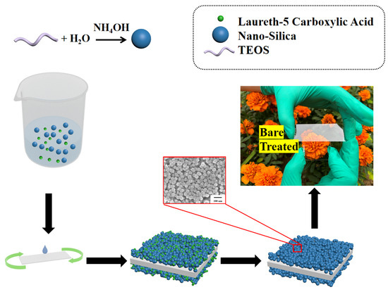
Figure 1.
Illustration of the preparation process of the porous anti-reflective coating (P-ARC).
2.4. Characterization
The micro-morphologies of the prepared coatings were observed using a scanning electron microscope (SEM, JSM-7500F, Tokyo, Japan) and measured using field emission high-resolution transmission electron microscopy (TEM, JEOL-F200, Tokyo, Japan). The AFM transmission spectrum and reflectance were measured using a UV-2550 UV–Visible-near-infrared spectrophotometer in the wavelength range of 300–900 nm. The refractive indices of the P-ARC and the NoP-ARC were measured using an ellipsometer (SE-VE, Wuhan EopticsTechnology Co., Ltd., Wuhan, China). Thermogravimetric (TG) curves were measured using a synchronous thermal analyzer (STA 449 F5, Netzsch, Selb, Germany) in the temperature range of 30 to 400 °C using a heating rate of 10 °C/min in the air.
2.5. Stability Test
When the P-ARC was subjected to harsh environmental conditions, its stability became a crucial factor to consider. There are various methods for testing the stability of a coating. Specifically, high-temperature and acid and alkali resistance tests were conducted to assess the coating’s durability in this work. At the same time, we tested the adhesion of the coating with 3M tape stripping tests.
3. Results and Discussion
3.1. Surface Morphologies
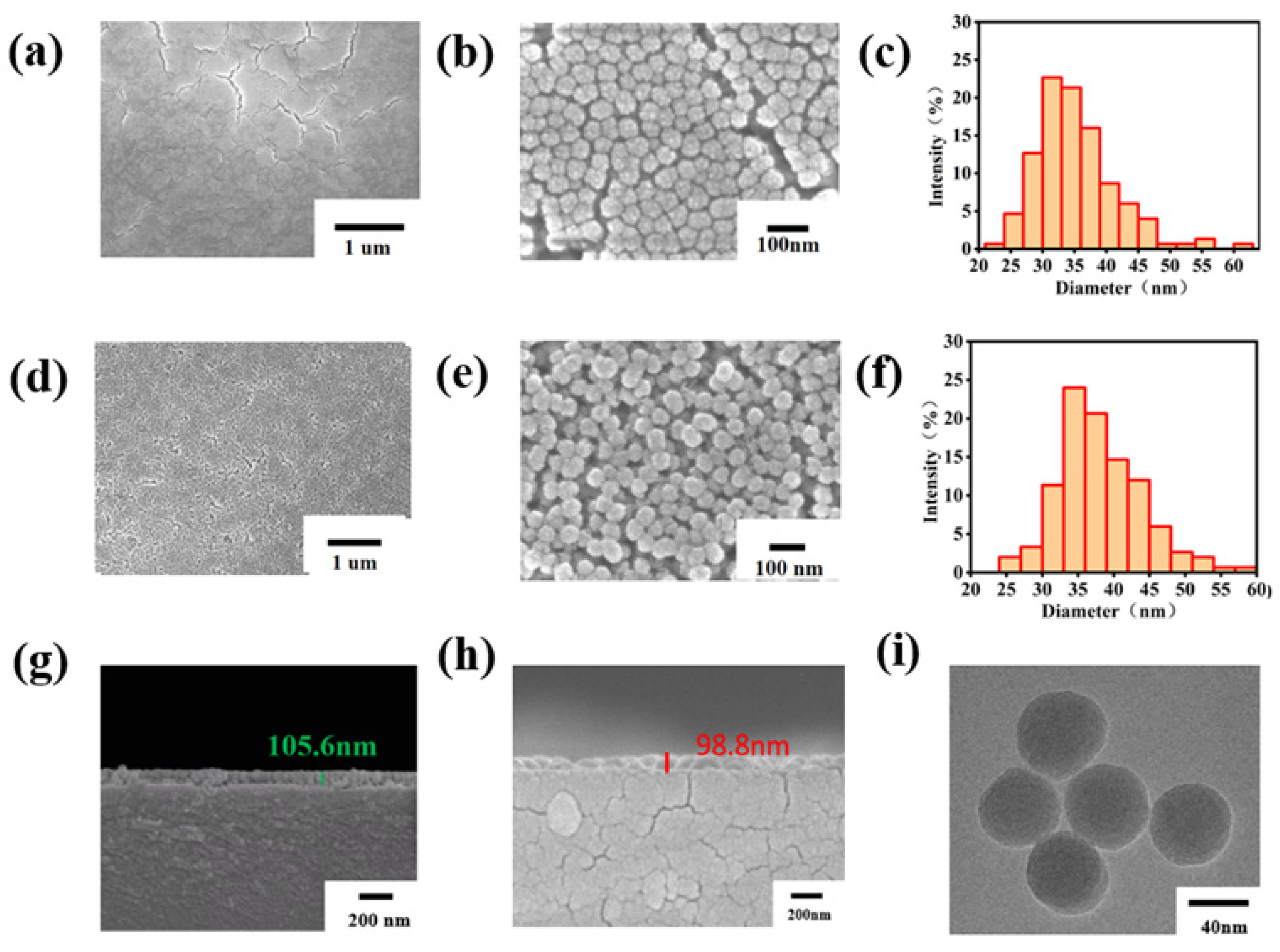
Figure 2 presents the SEM images of both the NoP-ARC and P-ARC. As observed in Figure 2a,b, numerous cracks appeared on the surface of the NoP-ARC after undergoing high-temperature treatment. Despite its smooth surface, the silicon particles were densely packed in an island-like formation. Conversely, it can be seen that the vesicular structure of the P-ARC was formed, which is illustrated in Figure 2d,e. LCA inhibited the dense arrangement of silica, and it started to decompose at 190 °C, resulting in the formation of numerous pores. Figure 2c,f depicts the particle size distribution of the AR coating and porous AR coating. Both the particle size distribution of the NoP-ARC and P-ARC followed a quasi-Gaussian distribution. The particle diameter of the P-ARC was slightly greater than that of the NoP-ARC and was more uniform. Further tests of the P-ARC thickness and NoP-ARC thickness (as shown in Figure 2g,h) showed that the thickness was approximately 105 nm for the P-ARC and approximately 98 nm for the NoP-ARC. The numbers shown in the figure are the thicknesses of the marks. The thickness difference between the two coatings was 7 cm within the margin of error. Through the TEM images displayed in Figure 2h, we can observe that the silica nanoparticles in the P-ARC were spherically shaped, with an average diameter of approximately 45 nm, which is consistent with the SEM results.

Figure 2.
(a) SEM image of the NoP-ARC; (b) SEM image of the enlarged NoP-ARC; (c) particle size distribution of the NoP-ARC; (d) SEM image of the P-ARC; (e) SEM image of the enlarged P-ARC; (f) particle size distribution of the P-ARC; (g) SEM image of the cross-section of the P-ARC; (h) SEM image of the cross-section of the NoP-ARC; (i) TEM images of the coating particles with the P-ARC.
3.2. Refractive Index and Anti-Reflection Properties of the Coating
In this part, the coating transmittance for the P-ARC is studied. Meanwhile, the coating transmittance under different layers is discussed, too. It can be seen that with the increase in the number of coating layers, the transmission of the coated glass plate increases first and then decreases. The reason is that the thickness of the coating becomes larger as the number of layers increases. When the incident light is perpendicular to the coating surface, the corresponding transmittance of the coating wavelength with different thicknesses is also different. As depicted in Figure 3b, the glass with the coating exhibited a peak transmittance of 99.5% and an average transmittance of 97.9% within the visible range, signifying a remarkable 5% improvement compared to standard glass. Figure 3c displays the refractive index of the coating measured using an ellipsometer at each wavelength within the visible range (the air refractive index was 1.0, the refractive index of glass is shown in Figure 3c, and the coating thickness was 100 nm). The results reveal that the refractive index of the NoP-ARC was approximately 1.32, whereas that of the P-ARC was as low as approximately 1.21. In addition, we conducted reflectance and absorptivity measurements of the P-ARC glass, and as illustrated in Figure 3d, the reflectance in the visible range was approximately 0.2%. These results provide further evidence of the excellent anti-reflection properties of the coating.
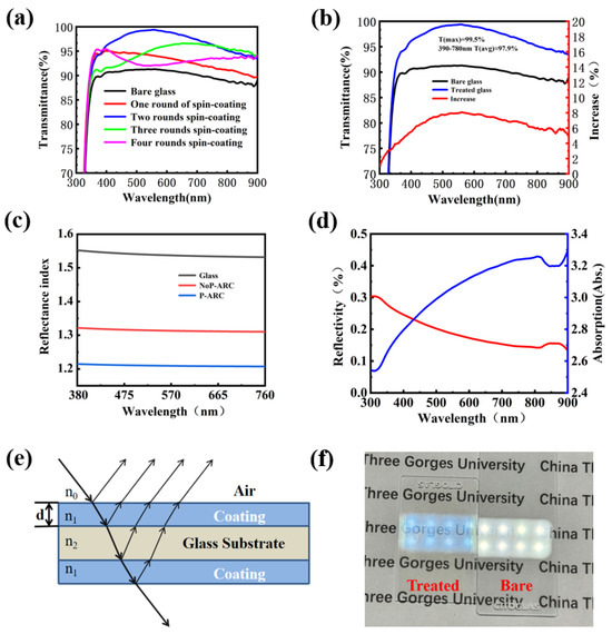
Figure 3.
(a) UV–Vis transmission spectra of the coating with different numbers of layers applied; (b) UV–Vis transmission spectra of coated and bare glass and their differences; (c) refractive index of the NoP-ARC, P-ARC, and glass; (d) absorption values and reflectance of the P-ARC; (e) light path diagram of the anti-reflection coating; (f) optical image of the coated glass.
The refractive index of the film is closely related to its structure. Here, the relationship between the porosity and the refractive index is discussed. Normally, when a low-refraction coating is prepared, the refractive index (np) of the coating is closely related to its porosity (p), and the relationship can be satisfied using the following formula [27]:
Here, n represents the refractive index of the dense film material. Obviously, in order to prepare a coating with low refraction, a more loose and porous structure is more favorable.
In order to further study the influence of reaction time and temperature of the silica sol on the transmittance (a wavelength of 550 nm), a statistical analysis was conducted on the reaction temperature and time for P-ARC preparation, as shown in Table 1. The observations indicate that variations in the reaction temperature and time have a remarkable impact on the transmittance of the coating. At a reaction temperature of 40 °C and a reaction time of 90 min, the layer attained maximum transmittance at 96.9%. When the temperature rose to 60 °C with a reaction time of 60 min, the coating exhibited even higher maximum transmittance at 99.5%. The transmittance of the prepared coating decreased significantly when the temperature reached 70 °C. It can be observed that the optimal reaction temperature was 60 °C, as higher or lower temperatures would lead to a decrease in the transmittance of the coating. In the entire reaction process, we concluded the optimal reaction temperature to be 60 °C; the reaction was not very efficient at low temperatures, while excessively high temperatures led to the evaporation of the ammonia in the bottle, thereby reducing the reaction rate. A reaction time of 60 min could achieve a maximum transmittance of 99.5%. When the reaction time exceeded 60 min, the transmittance of the coating decreased. We speculate that this is due to an excessive reaction, causing an increase in the diameter of the silicon particles in the solution, leading to a decrease in the transmittance.

Table 1.
Effect of the reaction time and temperature on the transmittance.
Figure 3e shows a mathematical sketch to illustrate the possible light path passing through the coated glass. As shown in Figure 3f, the coated glass and bare glass were placed on the paper, with an LED light positioned 50 cm above them. It can be observed that the light emitted from the LED lamp passed through both pieces of glass. However, it is difficult to read the words on the paper for naked glass because of the excessive reflection. It is much clearer for the P-ARC glass since it has a much smaller reflectivity.
Normally, one or more layers of a transparent medium with a low refractive index are coated onto a surface in order to minimize the optical loss caused by the reflection on the surface. The thickness of the coating has a significant impact on the anti-reflection effect, as demonstrated by the optical path diagram and path difference [28]. The thickness of the coating can be modified to achieve the desired level of anti-reflection according to the optical path difference formula [28]:
Here, n1 is the refractive index of the anti-reflection coating. According to the previous transmission spectra, SEM images, and refractive index, we know that when λ equals 550 nm, and n1 equals 1.22, we can calculate that d is approximately equal to 112.7 nm. This is not much different from the coating thickness we measured.
3.3. Thermal Stability and Acid and Alkali Resistance Tests for the Coating
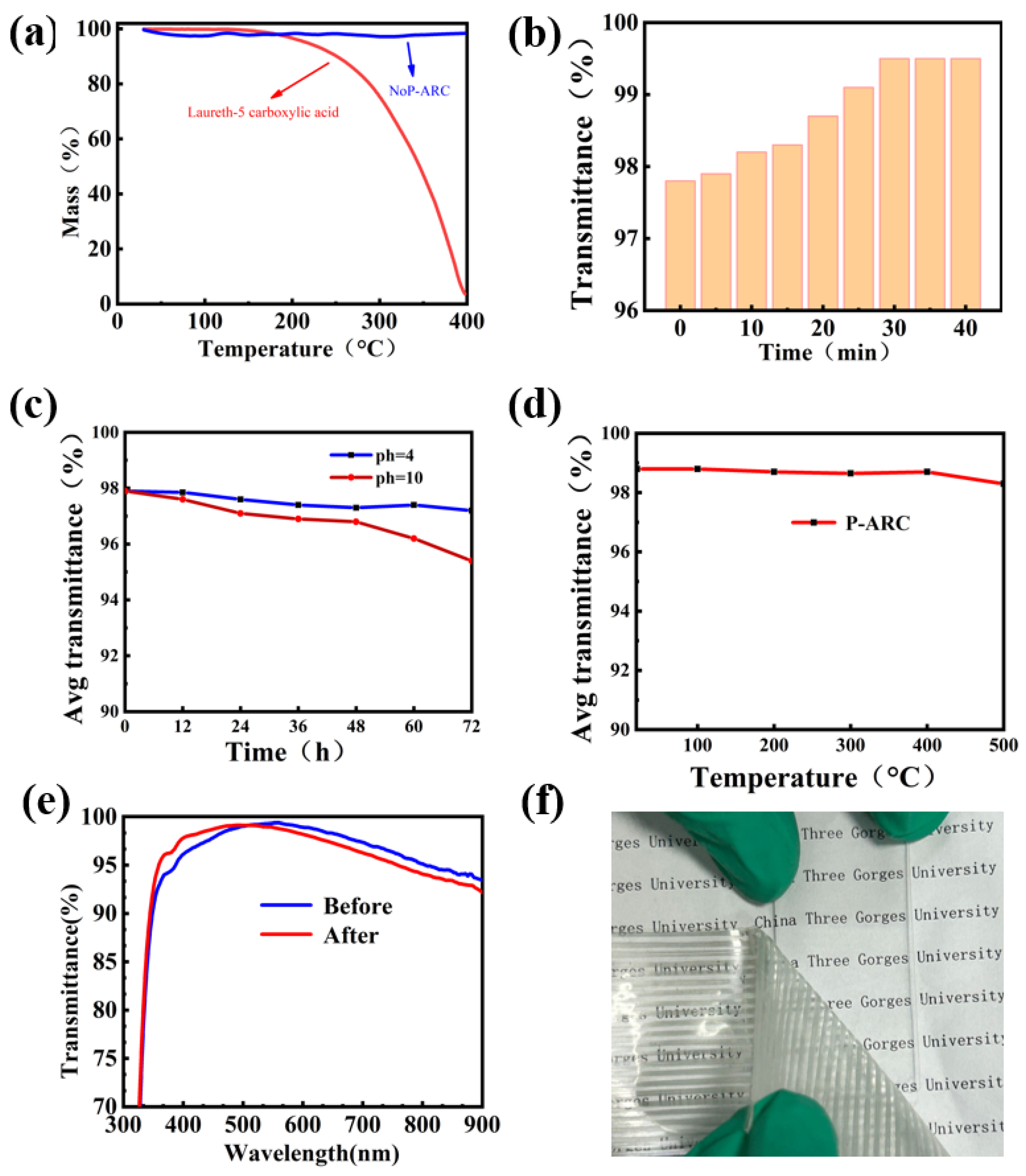
Chemical stability and thermal stability are imperative for practical purposes when it comes to anti-reflection coatings. Thermogravimetric analysis was conducted on both LCA and the NoP-ARC to validate the decomposition of LCA during high temperatures. As illustrated in Figure 4a, it can be observed that LCA begins to decompose at a temperature of 190 °C. The decomposition rate is correlated to the slope depicted in the figure. In contrast, AR remains intact even when subjected to temperatures as high as 400 °C because there is no LCA in the AR coating. So, it is reasonable for us to remove LCA at a temperature of 220 °C. We also examined the influence of the P-ARC annealing time on the transmittance at 220 °C. It is proved that the coating’s maximum transmittance before annealing was 97.8%. After annealing for 30 min, the coating’s maximum transmittance reached a peak of 99.5%, while with further continuous annealing, no further increase in the transmittance can be seen. This indicated that LCA was completely removed.
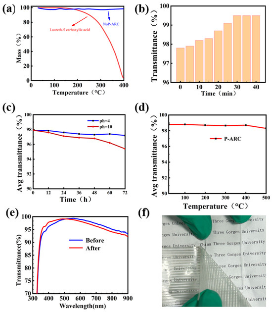
Figure 4.
(a) TG curve of the NoP-ARC and LCA; (b) relationship between the transmittance of the P-ARC and the firing time at 220 °C was examined; (c) transmittance of the P-ARC immersed in the solution with different pH values for 12, 24, 36, 48, 60, and 72 h; (d) high temperature on the transmittance of the P-ARC; (e) UV–Vis transmission spectra before and after the 3M tape test; (f) 3M tape test diagram.
In order to evaluate the chemical stability, we examined the average transmittance of the P-ARC following immersion in solutions with different pH values (pH = 4, 10) for varying time periods. The P-ARC was soaked and removed every 12 h, washed with water, and dried before testing. It is evident that the coating remained relatively stable under acidic conditions. After 72 h of immersion in a pH = 4 solution, the coating had an average transmittance of 97% in the visible range. Conversely, at pH = 10, the average transmittance of the coating exhibited a downward trend. The average transmittance was 96% after soaking for 60 h. In order to assess the thermal stability of the coating, we exposed it to various temperatures ranging from 100 °C to 400 °C for a duration of 10 h with 100 °C intervals. It can be observed that there was no significant change in the transmittance of the coating, even at a temperature as high as 400 °C. We also conducted an adhesion test using 3M tape (Figure 4f) [29]. The 3M tape was applied firmly onto the coating and then slowly peeled off to assess the light transmittance. It is important to note that the coating remained undamaged when subjected to a single application of 3M adhesive tape. As shown in Figure 4e, we tested the transmittance of the coating before and after it was subjected to a single damage event incurred using 3M tape. After a test using 3M tape, the transmission curve shifted to the left overall, but the average transmittance of the visible light portion only decreased by less than 0.22%. We speculate that this is due to the removal of the surface layer of silicon dioxide when peeling off the 3M tape, resulting in a thinner silicon dioxide coating and causing the transmission curve to shift to the left.
4. Conclusions
At a relatively low temperature (220 °C), residue-free porous medium calcination was utilized to prepare a porous anti-reflection coating, resulting in a high transmittance of 99.5%; the average transmittance in the visible range was 97.9%. A low refractive index of approximately 1.21 was achieved. The P-ARC film had good thermal stability, chemical stability, and mechanical stability, showing huge promise in solar cells, windshields, lenses, and other practical applications in optical components.
Author Contributions
Validation, T.L., F.Z., S.L. and W.J.; Investigation, X.L.; Writing—original draft, T.L.; Writing—review & editing, T.L., X.T. and W.C.; Supervision, T.X. and L.J.; Funding acquisition, X.T. All authors have read and agreed to the published version of the manuscript.
Funding
This research was funded by National Natural Science Foundation of China (Grant No. 52007104), Natural Science Foundation of Hubei Province (Grant No. 2022CFD036) and 111 Project (D20015) of China.
Institutional Review Board Statement
Not applicable.
Informed Consent Statement
Not applicable.
Data Availability Statement
Data are contained within the article.
Conflicts of Interest
The authors declare no conflict of interest.
References
- Wang, P.; Yan, X.; Zeng, J.; Luo, C.; Wang, C. Anti-Reflective Superhydrophobic Coatings with Excellent Durable and Self-cleaning Properties for Solar Cells. Appl. Surf. Sci. 2022, 602, 154408. [Google Scholar] [CrossRef]
- Oh, S.; Cho, J.-W.; Lee, J.; Han, J.; Kim, S.-K.; Nam, Y. A Scalable Haze-Free Antireflective Hierarchical Surface with Self-Cleaning Capability. Adv. Sci. 2022, 9, e2202781. [Google Scholar] [CrossRef] [PubMed]
- Erik, Z.; Stefan, K.; Mikael, J.; Jonas, S.; Petter, L.; Thomas, W. Durability of antireflective SiO2 coatings with closed pore structure. Sol. Energy Mater. Sol. Cells 2023, 261, 112521. [Google Scholar]
- Su, J.; Yin, L.; Qin, L.; Ma, N.; Huang, J. Preparation and performance of ZrAlN anti-reflective coatings for low-emissivity glasses. Ceram. Int. 2017, 43, 14616–14622. [Google Scholar] [CrossRef]
- Zambrano, D.F.; Villarroel, R.; Espinoza-González, R.; Carvajal, N.; Rosenkranz, A.; Montaño-Figueroa, A.G.; Arellano-Jiménez, M.J.; Quevedo-Lopez, M.; Valenzuela, P.; Gacitúa, W. Mechanical and microstructural properties of broadband anti-reflective TiO2/SiO2 coatings for photovoltaic applications fabricated by magnetron sputtering. Sol. Energy Mater. Sol. Cells 2021, 220, 110841. [Google Scholar] [CrossRef]
- Rahmanian, A.; Rahmani, A. Effects and properties of double-layer anti-reflective coating In2O3/Conic Al2O3 and three-layer anti-reflective coatings of TiO2/In2O3/Conic Al2O3 on silicon substrate. Optik 2017, 155, 163–170. [Google Scholar] [CrossRef]
- He, M.; Wang, P.; Xiao, P.; Jia, X.; Luo, J.; Jiang, B. Hollow silica nanospheres synthesized by one-step etching method to construct optical coatings with controllable ultra-low refractive index. Colloids Surf. A Physicochem. Eng. Asp. 2023, 670, 131433. [Google Scholar] [CrossRef]
- Gema San, V.; Nuria, G.; Meryem, F.; Ángel, M.; Patricia, S.; Aránzazu, F.-G. Study of abrasion tests for antireflective and antisoiling/antireflective coatings on glass solar tubes. Sol. Energy 2023, 252, 134–144. [Google Scholar]
- Nakamura, M.; Mano, I.; Taniguchi, J. Fabrication of micro-lens array with antireflection structure. Microelectron. Eng. 2019, 211, 29–36. [Google Scholar] [CrossRef]
- Li, W.; Tan, X.; Zhu, J.; Xiang, P.; Xiao, T.; Tian, L.; Yang, A.; Wang, M.; Chen, X. Broadband antireflective and superhydrophobic coatings for solar cells. Mater. Today Energy 2019, 12, 348–355. [Google Scholar] [CrossRef]
- Tao, C.; Yan, H.; Yuan, X.; Yin, Q.; Zhu, J.; Ni, W.; Yan, L.; Zhang, L. Sol-gel based antireflective coatings with superhydrophobicity and exceptionally low refractive indices built from trimethylsilanized hollow silica nanoparticles. Colloids Surf. A Physicochem. Eng. Asp. 2016, 509, 307–313. [Google Scholar] [CrossRef]
- Gruzd, A.; Tokarev, A.; Tokarev, I.; Kuksenkov, D.; Minko, S. All-Nanoparticle Monolayer Broadband Antireflective and Self-Cleaning Transparent Glass Coatings. ACS Appl. Mater. Interfaces 2021, 13, 6767–6777. [Google Scholar] [CrossRef]
- Wu, Y.; Tan, X.; Wang, Y.; Tao, F.; Yu, M.; Chen, X. Nonfluorinated, transparent, and antireflective hydrophobic coating with self-cleaning function. Colloids Surf. A Physicochem. Eng. Asp. 2021, 634, 127919. [Google Scholar] [CrossRef]
- Lim, J.H.; Leem, J.W.; Yu, J.S. Solar power generation enhancement of dye-sensitized solar cells using hydrophobic and antireflective polymers with nanoholes. RSC Adv. 2015, 5, 61284–61289. [Google Scholar] [CrossRef]
- Pfeiffer, K.; Ghazaryan, L.; Schulz, U.; Szeghalmi, A. Wide-Angle Broadband Antireflection Coatings Prepared by Atomic Layer Deposition. ACS Appl. Mater. Interfaces 2019, 11, 21887–21894. [Google Scholar] [CrossRef] [PubMed]
- Li, B.; Niu, G.; Sun, L.; Yao, L.; Wang, C.; Zhang, Y. Design optimization and antireflection of silicon nanowire arrays fabricated by Au-assisted chemical etching. Mater. Sci. Semicond. Process. 2018, 82, 1–8. [Google Scholar] [CrossRef]
- Yuan, Y.; Lu, X.; Yan, G.; Hong, R. Sol-gel preparation of antireflective coatings with abrasion resistance by base/acid double catalysis and surface treatment. Sol. Energy 2017, 155, 1366–1372. [Google Scholar] [CrossRef]
- Sun, X.; Hu, K.; Tu, J.; Chen, K. Design and preparation of superhydrophobic, broadband and double-layer antireflective coatings. Surf. Interfaces 2021, 24, 101135. [Google Scholar] [CrossRef]
- Xing, Z.; Tay, S.-W.; Ng, Y.H.; Hong, L. Porous SiO2 Hollow Spheres as a Solar Reflective Pigment for Coatings. ACS Appl. Mater. Interfaces 2017, 9, 15103–15113. [Google Scholar] [CrossRef]
- Zhang, X.; Lan, P.; Lu, Y.; Li, J.; Xu, H.; Zhang, J.; Lee, Y.; Rhee, J.Y.; Choy, K.-L.; Song, W. Multifunctional Antireflection Coatings Based on Novel Hollow Silica–Silica Nanocomposites. ACS Appl. Mater. Interfaces 2014, 6, 1415–1423. [Google Scholar] [CrossRef]
- Innocenzi, P.; Malfatti, L.; Soler-Illia, G.J.A.A. Hierarchical Mesoporous Films: From Self-Assembly to Porosity with Different Length Scales. Chem. Mater. 2011, 23, 2501–2509. [Google Scholar] [CrossRef]
- Sel, O.; Kuang, D.; Thommes, M.; Smarsly, B. Principles of hierarchical meso- and macropore architectures by liquid crystalline and polymer colloid templating. Langmuir 2006, 22, 2311–2322. [Google Scholar] [CrossRef] [PubMed]
- Boudot, M.; Boissière, C.; Burov, E.; Gacoin, T. Engineering of Silica Thin-Film Nanoporosity via Alkali-Ion-Assisted Reconstruction. Chem. Mater. 2019, 31, 2390–2400. [Google Scholar] [CrossRef]
- Tao, C.; Yan, H.; Yuan, X.; Yin, Q.; Zhu, J.; Ni, W.; Yan, L.; Zhang, L. Detailed analysis and formation mechanism of superhydrophobic antireflective coatings with adjustable refractive index from trimethylsilanized silica nanoparticles. J. Sol-Gel. Sci. Technol. 2016, 80, 10–18. [Google Scholar] [CrossRef]
- Sun, M.-H.; Huang, S.-Z.; Chen, L.-H.; Li, Y.; Yang, X.-Y.; Yuan, Z.-Y.; Su, B.-L. Applications of hierarchically structured porous materials from energy storage and conversion, catalysis, photocatalysis, adsorption, separation, and sensing to biomedicine. Chem. Soc. Rev. 2016, 45, 3479–3563. [Google Scholar] [CrossRef] [PubMed]
- Yang, X.-Y.; Chen, L.-H.; Li, Y.; Rooke, J.C.; Sanchez, C.; Su, B.-L. Hierarchically porous materials: Synthesis strategies and structure design. Chem. Soc. Rev. 2016, 46, 481–558. [Google Scholar] [CrossRef] [PubMed]
- Yao, Y.; Lee, K.T.; Sheng, X.; Batara, N.A.; Hong, N.; He, J.; Xu, L.; Hussain, M.M.; Atwater, H.A.; Lewis, N.S.; et al. Porous Nanomaterials for Ultrabroadband Omnidirectional Anti-Reflection Surfaces with Applications in High Concentration Photovoltaics. Adv. Energy Mater. 2016, 7, 1601992. [Google Scholar] [CrossRef]
- Li, K.; Li, M.; Xu, C.; Du, Z.; Chen, J.; Zou, F.; Zou, C.; Xu, S.; Li, G. A TiO2 nanotubes film with excellent antireflective and near-perfect self-cleaning performances. J. Mater. Sci. Technol. 2021, 88, 11–20. [Google Scholar] [CrossRef]
- Wu, B.; Lyu, J.; Peng, C.; Jiang, D.; Yang, J.; Yang, J.; Xing, S.; Sheng, L. Inverse infusion processed hierarchical structure towards superhydrophobic coatings with ultrahigh mechanical robustness. Chem. Eng. J. 2020, 387, 124066. [Google Scholar] [CrossRef]


Disclaimer/Publisher’s Note: The statements, opinions and data contained in all publications are solely those of the individual author(s) and contributor(s) and not of MDPI and/or the editor(s). MDPI and/or the editor(s) disclaim responsibility for any injury to people or property resulting from any ideas, methods, instructions or products referred to in the content. |
© 2024 by the authors. Licensee MDPI, Basel, Switzerland. This article is an open access article distributed under the terms and conditions of the Creative Commons Attribution (CC BY) license (https://creativecommons.org/licenses/by/4.0/).