1. Introduction
Among the primary high-entropy alloy (HEA) families, 3d transition-metal-based high-entropy alloys such as CoCrFeMnNi single-phase alloy with an FCC crystal have attracted the attention of scientists since they exhibit combined mechanical properties including strength/ductility, corrosion resistance, and high thermal stability [
1,
2]. The mechanical properties of 3d transition metals based on high-entropy alloys can further be enhanced by adding Al, a BCC inducer that promotes the phase transition from FCC to BCC with the increasing Al content [
3,
4,
5]. It has been reported that the formation of a new BCC phase in the AlxCoCrFeNi alloy system can be associated with the lattice distortion induced by the atomic size difference [
3]. In recent years, eutectic high-entropy alloys (EHEAs) have emerged as one of the most popular classes of HEAs as they exhibit a nano-lamellar eutectic microstructure composed of BCC and FCC phases, which improve the material’s strength, ductility, and microstructure stability [
6,
7,
8]. It was proposed by Lu et al. in 2014 [
9] that an as-cast AlCoCrFeNi
2.1 comprising the CoCrFe phase (ductile FCC phase) and the NiAl phase (high-strength B2 phase) demonstrates promising properties with excellent strength (1186 MPa) and ductility (22.8%) [
9].
On the other hand, AlCoCrFeNi
2.1 EHEA coatings exhibit excellent surface hardness, corrosion resistance, and wear resistance [
10]. They also possess good thermal stability and hot corrosion performance by laser cladding [
11]. The fabrication of coatings involves various techniques, including laser deposition [
12], thermal spray [
13], vapor deposition [
14], and powder metallurgy [
15,
16,
17]. Mechanical alloying (MA) is one of the most promising techniques for fabricating coatings by solid-state powder processing. MA is a solid-state powder metallurgy and is capable of synthesizing various nanostructured materials by repeated cold welding, fracturing, and rewelding of powder particles in a high-energy ball mill. Nano-oxide particles can be introduced into the material matrix by mechanical alloying to generate a uniform distribution of particles and act as a pinning point to impede the dislocation movement, enhancing the creep resistance of materials. It is also noteworthy that a high surface activation energy promotes chemical reactions and bonding between the substrate and coating powders during high-energy ball milling and thus enhances the wear resistance and mechanical properties of the coating materials [
17,
18,
19]. It has also been reported that AlCoCrFeNi
2.1 added with oxide dispersoids using laser cladding can significantly improve the microstructure uniformity, surface hardness, and corrosion resistance of the composite coatings [
20].
However, research on EHEA coatings by mechanical alloying is still minimal. Therefore, in this work, the model AlCoCrFeNi2.1 coatings with and without the addition of Y2O3 dispersoids on the substrate of stainless steels fabricated through mechanical alloying were investigated. The model coatings were also subjected to annealing heat treatment to examine the various states during the ball milling process. The model AlCoCrFeNi2.1 bulk materials were prepared by MA followed with compaction and high-temperature sintering. Thus, the aims of this work are to better understand the effects of ball milling, consolidation, and sintering on the characteristics of AlCoCrFeNi2.1 between the coatings and bulk materials. It also aims to clarify the role of Y2O3 in the coatings and bulk materials and how it influences the material’s behavior and oxidation.
2. Materials and Methods
The starting materials used were commercial powders of Al, Co, Cr, Fe, and Ni with a purity of 99.9% and a particle size range of 15–50 μm. The morphologies of the initial powders are mostly for near-spherical particles produced by gas atomization techniques. AlCoCrFeNi2.1 and AlCoCrFeNi2.1 added with 2 wt.% of Y2O3 model materials were designed in this study. In this study, 304 stainless steel balls with a diameter of 7 mm were employed as substrate materials during ball milling. Mechanical alloying was performed using a Retsch PM100 instrument (Retsch, GmbH, Haan, Germany) at a speed of 300 rpm under the BPR ratio of 10:1 for durations of 4 h, 8 h, and 16 h. The vial and ball materials used in this study were tungsten carbide. The powder preparation was conducted in a glovebox filled with argon gas to prevent contamination, and the powder was then loaded into a ball mill for the mechanical alloying process. In this stage, the alloyed powders were coated on the substrate of stainless steel balls during ball milling. An annealing treatment was further performed on the model coating samples under a high-vacuum furnace (10−5 torr) at 1050 °C for one hour. For the bulk materials, the alloyed powders were consolidated using a uniaxial hydraulic press with a pressure of 170 kg/cm2 for 15 min, followed by high-vacuum sintering (10−5 torr) at 1050 °C for one hour. The alloyed powders and bulk samples were characterized by an X’Pert PRO X-ray diffractometer (XRD, PANalytical, Almelo, The Netherlands). Microstructure characterization and chemical composition analysis of the model coatings and bulk materials were conducted using a Hitachi-4700 scanning electron microscope (SEM, Hitachi High-Tech Corporation, Tokyo, Japan) and energy dispersive spectroscopy (EDS). Phase identification and crystal structure were further investigated on an FEI Tecnai F20 G2 Field Emission Gun TEM (FEI Company, Hillsboro, US). Vickers hardness tests were performed using a load of 9.8 N for a holding time of 15 s at room temperature. Compressive tests were conducted by a universal test machine with a capacity of 100 KN at the strain rate of 10−3 S−1.
3. Results and Discussion
3.1. Characterization of the Model Alloy Powders
Figure 1 shows the XRD patterns of the AlCoCrFeNi
2.1 powders at different milling times. A strong peak was observed at 2-theta of ~45 degrees in the unmilled powder sample, corresponding to the overlapping of Al, Co, Cr, Fe, and Ni elements. After 4 h of milling, the XRD pattern exhibits distinct peak broadening, which indicates that the material underwent repeated cold welding, fracturing, and rewelding of powder particles during mechanical alloying. Thereby, severe plastic deformation occurred by high-energy ball milling, which promoted the atomic diffusion and solubility between constituent elemental powders. In this case, the transitional phase was generated and may represent the transformation of the material from its initial powder form into a complex structure. It reveals that the ball milling process has a significant impact on the phase formation and characteristics of the material. As the ball milling time increased to 8 h and 16 h, the dual-phase structure was formed, composed of a CoCrFeNi solid solution single phase with an FCC crystal structure and an AlNi phase with a BCC crystal structure. It is commonly found in AlCoCrFeNi alloy systems [
6,
21]. It should also be noted that the Co, Cr, Fe, and Ni elements have a higher melting point than Al. Therefore, the high-melting-point elements possess slower diffusion rates during mechanical alloying. Ni has a strong affinity for Al to form the B2-AlNi phase. Thereby, in this case, the lower-melting-point element of Al with a higher alloying rate can readily react with Ni to form bcc-based structure. On the other hand,
Figure 2 shows the XRD patterns of the AlCoCrFeNi
2.1 alloy powders added with Y
2O
3 oxides as a function of milling time. It can be seen that the presence of oxide particles was detected in the unmilled stage. However, after 4 h of milling, the peaks of the Y
2O
3 phase disappeared, which is related to the broadening effect introduced by mechanical alloying. Generally, the XRD patterns have a similar tendency between the samples with and without Y
2O
3 addition (see
Figure 1 and
Figure 2).
3.2. Characterization of the Model Coatings
3.2.1. SEM/EDS Observation of the Coatings
Figure 3 illustrates SEM images of the AlCoCrFeNi
2.1 coatings that have undergone mechanical alloying for different milling times. EDS analysis corresponding to the phases of the various coatings identified in
Figure 3,
Figure 4,
Figure 5 and
Figure 6 can be seen in
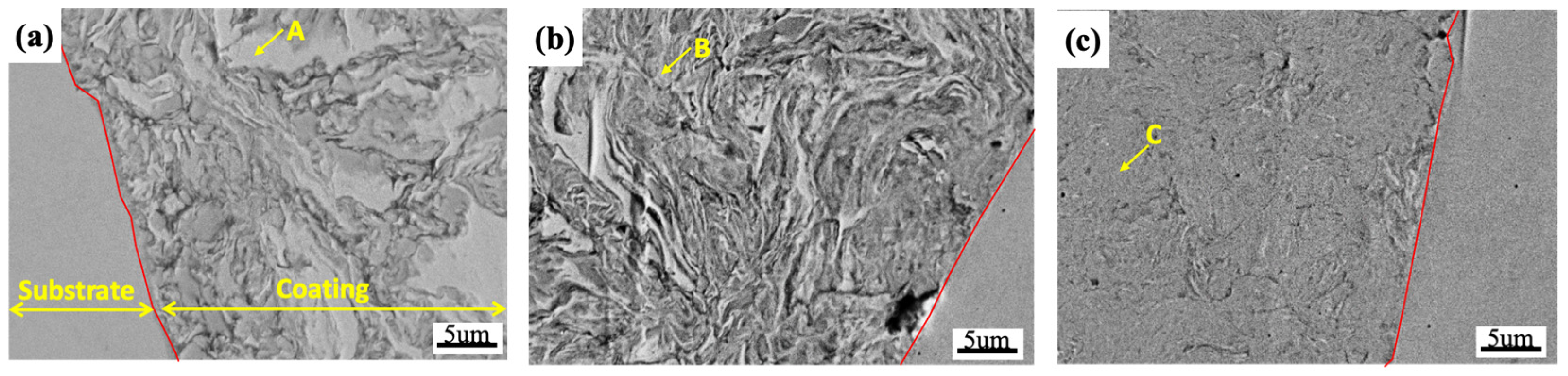
Table 1. The coating with 4 h of milling, see
Figure 3a, shows two distinct regions. One is for the laminar structure with fine grain size generated by the milling process. The other area has a Ni-rich phase with the bright contrast labeled as point A. In this case, it suggests that the high melting point of Ni results in a relatively slow diffusion rate at the initial stage of mechanical alloying, causing the formation of the Ni-rich phase. In
Figure 3b, the coating with a completed laminar structure was obtained after 8 h of milling. It reveals that the Ni-rich phase tends to transfer into the AlNi phase, see point B. This can be attributed to the fact that the Al is preferably formed with elements from the 3d transition metal series (Ni, Co, Fe, Cr, Mn, etc.) [
22]. Among these elements, Ni exhibits the lowest mixing enthalpy (~−22 kJ/mol) [
23,
24], and therefore, a stable phase composed of Al and Ni can be promoted in the coating. As the ball milling time increases to 16 h, the microstructure of the coating is progressively refined and becomes more uniform, see
Figure 3c. A considerable reduction in the Ni-rich phase is evident. The coating, see point C, displays a uniform composition. The Ni-rich phase can completely dissolve into the coating layer. It indicates a solid solution effect where elements undergo dissolution after mechanical alloying, leading to a finer and more homogeneous microstructure.
On the contrary, yttria has a relatively high structural stability at elevated temperatures [
25] and is commonly used as dispersion strengthening for alloy design.
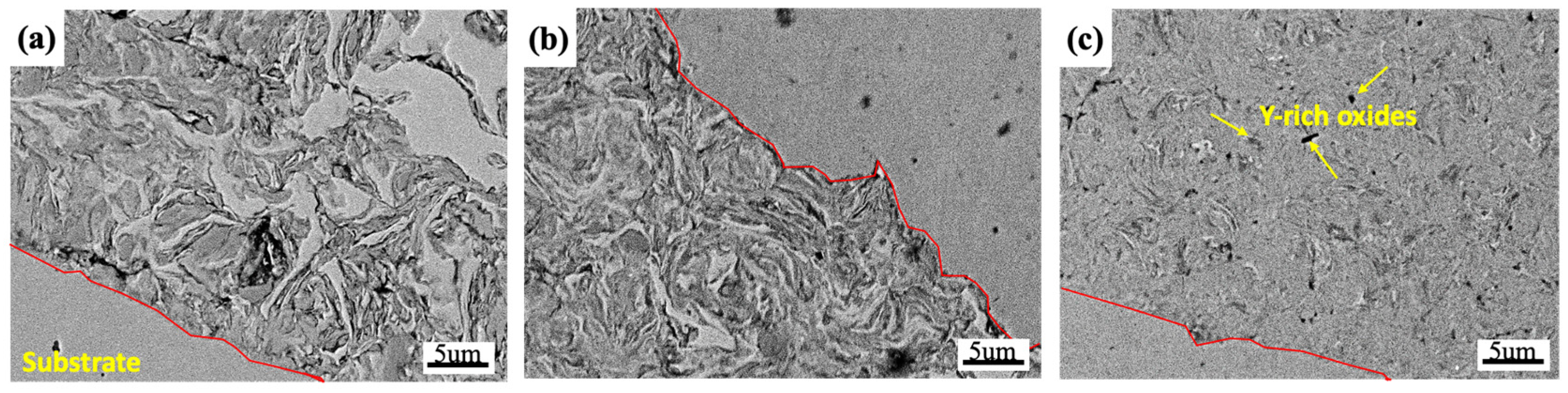
Figure 4 shows the AlCoCrFeNi
2.1 coatings with the addition of Y
2O
3 subjected to the different milling durations. In the coatings with 4 h and 8 h of milling, see
Figure 4a,b, the Ni-rich phase and lamellar structure were still observed in the yttria-added coatings. They have a microstructure similar to that of the Y
2O
3-free coatings, as shown in
Figure 3a,b. However, several small black particles were obtained after a long milling process (16 h), see
Figure 4c, where a high concentration of O and Y was detected, corresponding to the formation of Y-rich oxide phases (see yellow arrow). It should be noted that nano-Y
2O
3 particles can interact with other constituent elements during the milling process. Thus, complex and coarse Y-rich oxides are formed after a lengthy milling procedure. Adding nano-Y
2O
3 dispersoids as dispersion strengthening is vital in determining the mechanical properties of materials at elevated temperatures [
26,
27].
3.2.2. SEM/EDS Observation of the Coatings after Annealing
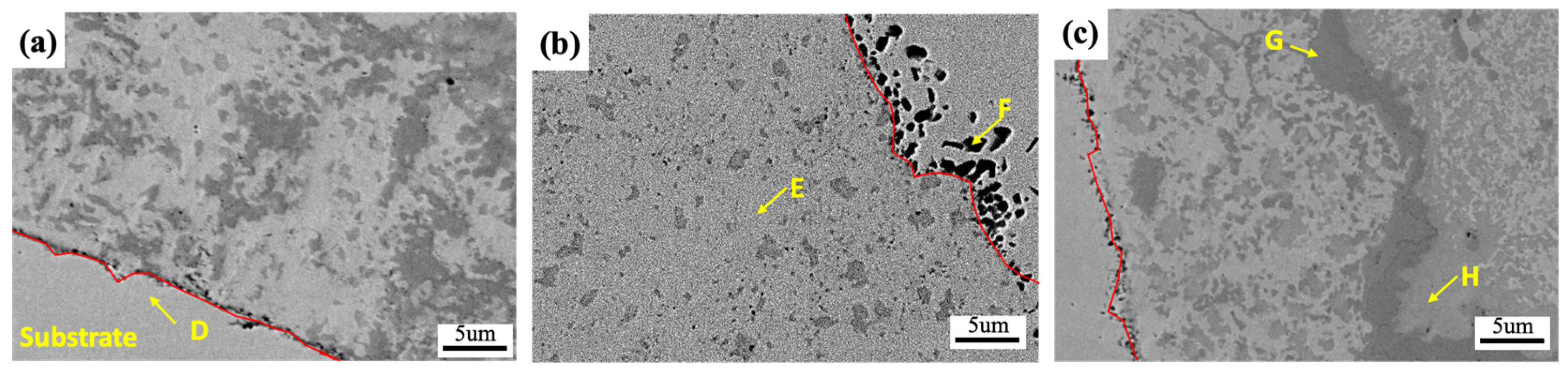
Figure 5 demonstrates the AlCoCrFeNi
2.1 coatings after mechanical alloying followed by annealing treatment at 1050 °C for 1 h. It is clear to observe that the formation of a dual-phase microstructure was obtained after annealing. The region with a bright contrast is predominantly composed of Co, Cr, Fe, and Ni elements, suggesting the formation of an FCC solid solution phase. In contrast, the dark area is primarily composed of Al and Ni, representing the BCC phase. Moreover, the interface between the substrate and the coating contains a high level of Fe, indicating the occurrence of the interaction and atomic diffusion induced by the high-temperature annealing treatment, see point D in
Figure 5a. The annealed coating, after 8 h of milling, exhibits several black particles with a high Al concentration generated at the interface between the coating and the substrate, as shown in point F of
Figure 5b. The formation of Al-rich phases could be attributed to the melting point of Al, which is significantly lower than that of other elements in the coating. Thus, the diffusion rate of Al is faster, making it prone to the formation of Al-rich phases at the interfacial boundaries. In this case, the depletion of aluminum in the coating caused by a rapid diffusion and Al-rich phase formation can impede the formation ability of AlNi phases and change the volume fraction and grain size of the phases, as shown in
Figure 5b.
Figure 5c shows the microstructure of the annealed coating after 16 h of milling. Apart from the formation of the dual-phase microstructure, Cr-rich phases were also observed in the coating, see point G in
Figure 5c. This indicates that during a long milling process, cold welding dominates over fracturing, leading to an increase in the strain energy of the coating. Therefore, it may be assumed that the high storage energy can further promote the formation of the Cr-rich or Laves phases after high-temperature annealing. Additionally, it has been proposed that the Cr-rich phase tends to precipitate in the Al-Ni phase [
21,
28]. The precipitation of the Cr-rich phase causes the Al-rich phase formed at the boundaries to diffuse back into the coating. Consequently, many AlNi phases are formed along with the Cr-rich phases. It can be concluded that the ball milling process significantly influences the microstructure and composition of the coatings. The subsequent annealing treatment can further promote phase formation and phase transformation in the coatings.
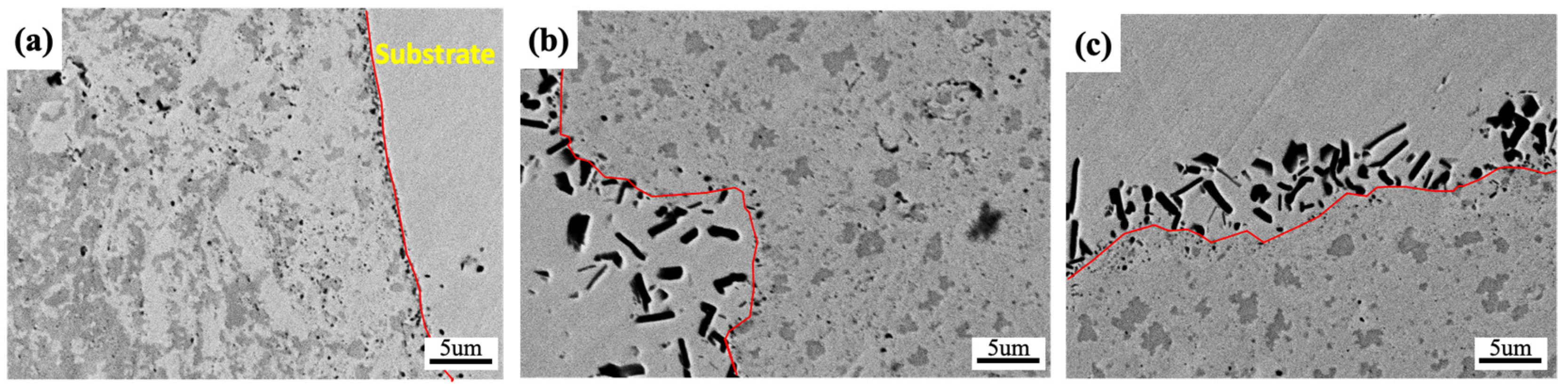
Figure 6 shows the microstructure of the AlCoCrFeNi
2.1 coating with Y
2O
3 after annealing treatment. A heterogeneous coating structure consisting of the BCC/FCC phases with non-uniform composition was obtained at 4 h of milling, due to insufficient energy accumulation at the initial milling stage. Additionally, an interphase that occurred between the coating and the substrate was found, see
Figure 6a, indicating the rapid interaction of elements at the interface induced by the significance of the annealing treatment. Conversely, many black elongated phases with a high content of Al, Y, and O elements were generated at the interfacial boundaries, as shown in
Figure 6b,c. It can be assumed that the surface of the milling balls undergoes severe plastic deformation during mechanical alloying, providing high energy at the interface between the substrate and the coating. In this case, there is a favorable affinity between Al and yttria [
25,
27], and thereby, the presence of Y
2O
3 could act as nunation sites for the formation of Al-Y-O oxide phases. However, after 16 h of milling, see
Figure 6c, the coating has no Cr-rich phase formation in comparison with the Y
2O
3-free annealed coating, see
Figure 5c. It is supposed that the Al-Y-O oxides were considerably formed, which can cause a substantial reduction in the AlNi phase due to the Al depletion. The reduction in and refinement of the AlNi phases make the precipitation of the Cr-rich phase difficult, leading to the disappearance of the Cr-rich phase after a long milling time.
3.3. Characterization of the Bulk Alloys
3.3.1. SEM/EDS Observation
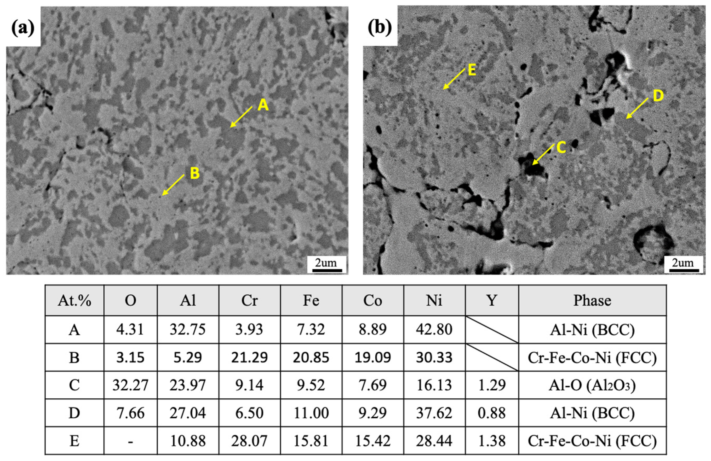
Figure 7 illustrates the SEM images of the bulk AlCoCrFeNi
2.1 alloys after 16 h of milling, followed by compaction and sintering. The microstructure of the bulk model alloys can be seen in
Figure 7a. The results indicate that the dual-phase structure composed of the BCC AlNi and FCC CrFeCoNi phases was observed, as shown in points A and B of
Figure 7a. However, several large pores were found in the microstructure of the model alloy with the Y
2O
3 addition, see
Figure 7b. The pore is predominantly filled with yttria-containing alumina (see point C). It is believed that there is a good affinity between Al and yttria, forming Al-Y-O by the atomic interaction and diffusion through ball milling and sintering processes. The volume fraction and average particle size of different phases in the bulk model alloys are given in
Table 2. The BCC AlNi phase has about a 35% volume fraction in both model alloys. However, the generation of pores of about 6% was obtained in the bulk sample with the yttria addition. The average grain size of the material decreased from 0.4 μm to 0.34 μm. This indicates that the presence of oxide dispersoids can refine the microstructure of the model alloy.
In the comparison between the annealed coatings and the sintered bulk materials, some crucial features of points should be emphasized here. Firstly, excessive and accumulated cold welding takes place at the coating layers after a long mechanical alloying process. It can accumulate many crystal defects, facilitating the precipitation of the Cr-rich phase. Secondly, the annealed coatings tend to interact with the substrate, forming an interface layer. The presence of Al-rich phases at the interface impedes the formability of the AlNi phase due to the Al depletion at the coating layer. Finally, the bulk materials exhibit a homogenous microstructure and uniform composition after undergoing the compaction and sintering processes (see points A and B in
Figure 7a). The results can be attributed to there being no substrate effect for bulk materials during mechanical and thermal processing. Consequently, only solid solution interactions between constituting elements take place, resulting in a pronounced homogeneity of microstructure and chemical composition in the bulk alloys.
3.3.2. TEM Investigation
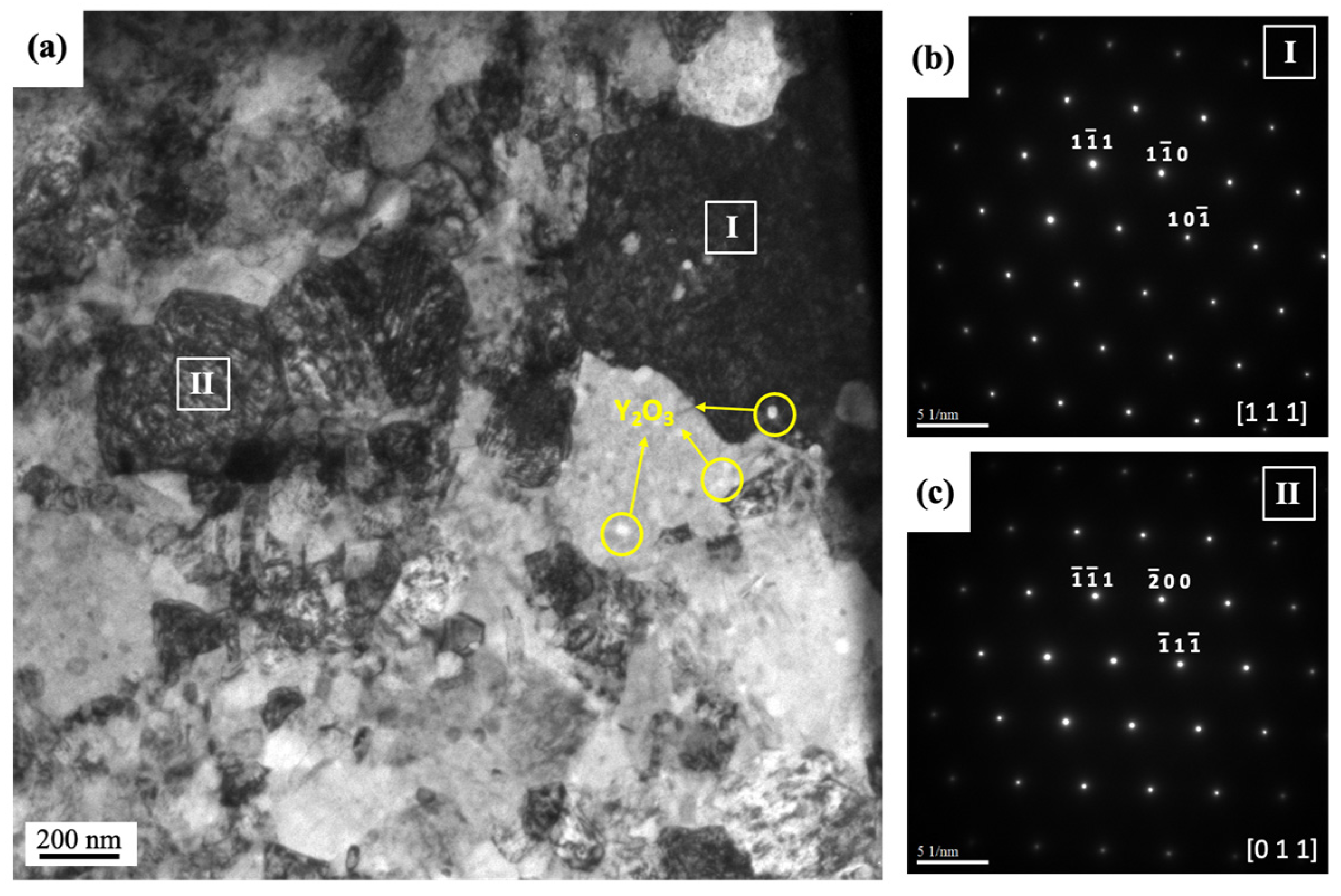
Figure 8a demonstrates a bright-field (BF) TEM image of the bulk AlCoCrFeNi
2.1 alloy added with Y
2O
3. The two large grains (~500 nm) with different contrasts labeled as “I” and “II” have been further investigated. A high level of Ni and Al elements with a composition of 44.53Ni-30.36Al (at.%) was detected in the position “I”, suggesting the formation of the AlNi phase. According to the selected area diffraction (SAD), see
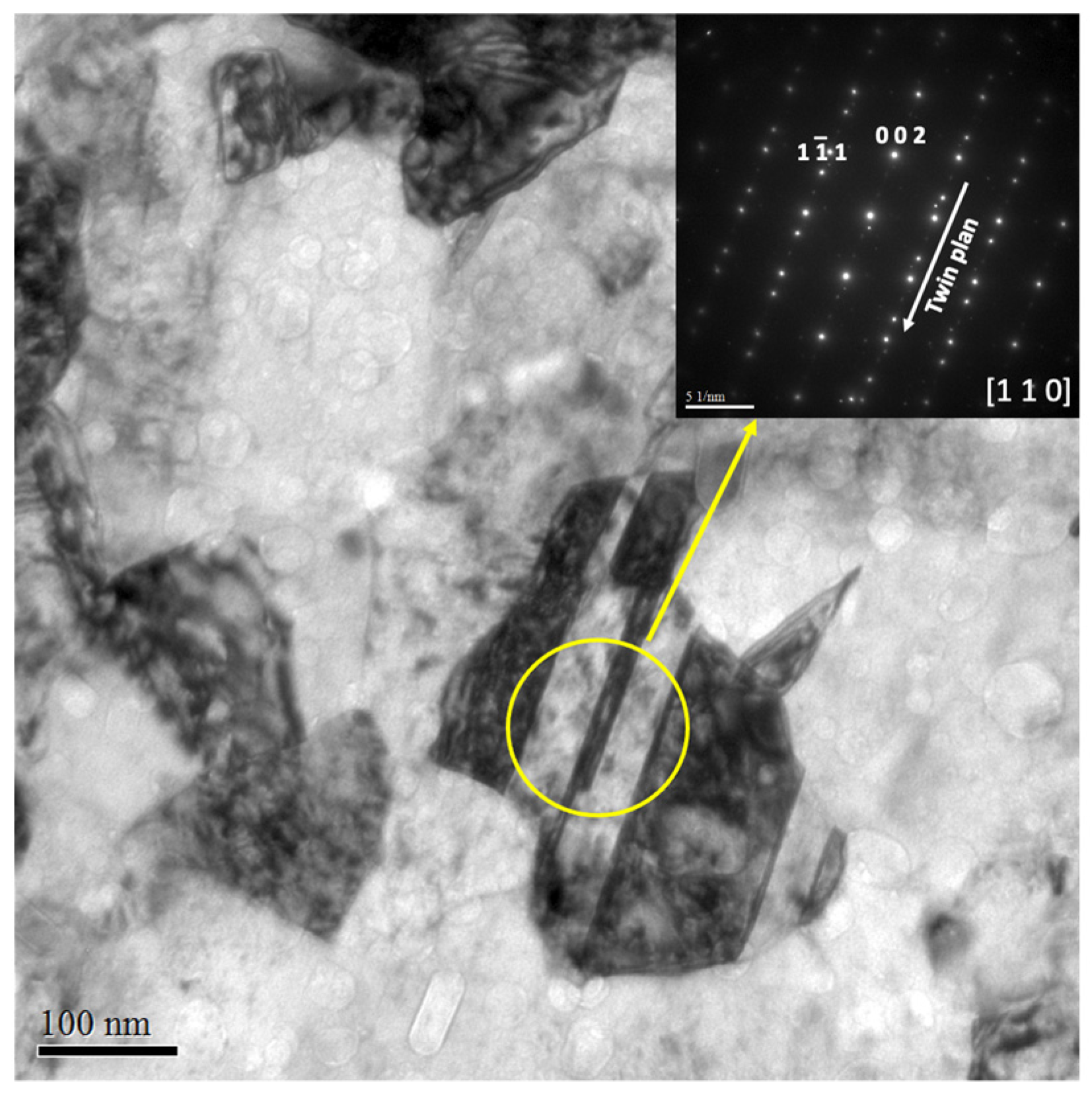
Figure 8b, the AlNi phase has been indexed as an ordered BCC (B2) structure with the lattice parameter of 2.89 Å along the zone axis of [111]. On the other hand, in position “II”, the grain contains a high concentration of Co, Cr, Fe, and Ni elements with a composition of 29.71Ni-22.27Cr-20.87Fe-18.96Co (at.%). The crystal structure of the Ni-rich phase has been identified as an FCC phase with a lattice parameter of 3.59 Å along the zone axis of [011]. It can be seen that the twinned structure was observed in the FCC phase, as shown in
Figure 9. This phenomenon can be related to the low stacking fault energies (SFEs) taking place in FCC structure materials, which promoted the deformation twinning, strain hardening rate, and plasticity [
29]. In this case, deformation twins of the CoCrFeNi FCC phase in the alloy form to accommodate strains induced by severe plastic deformation during high-energy ball milling.
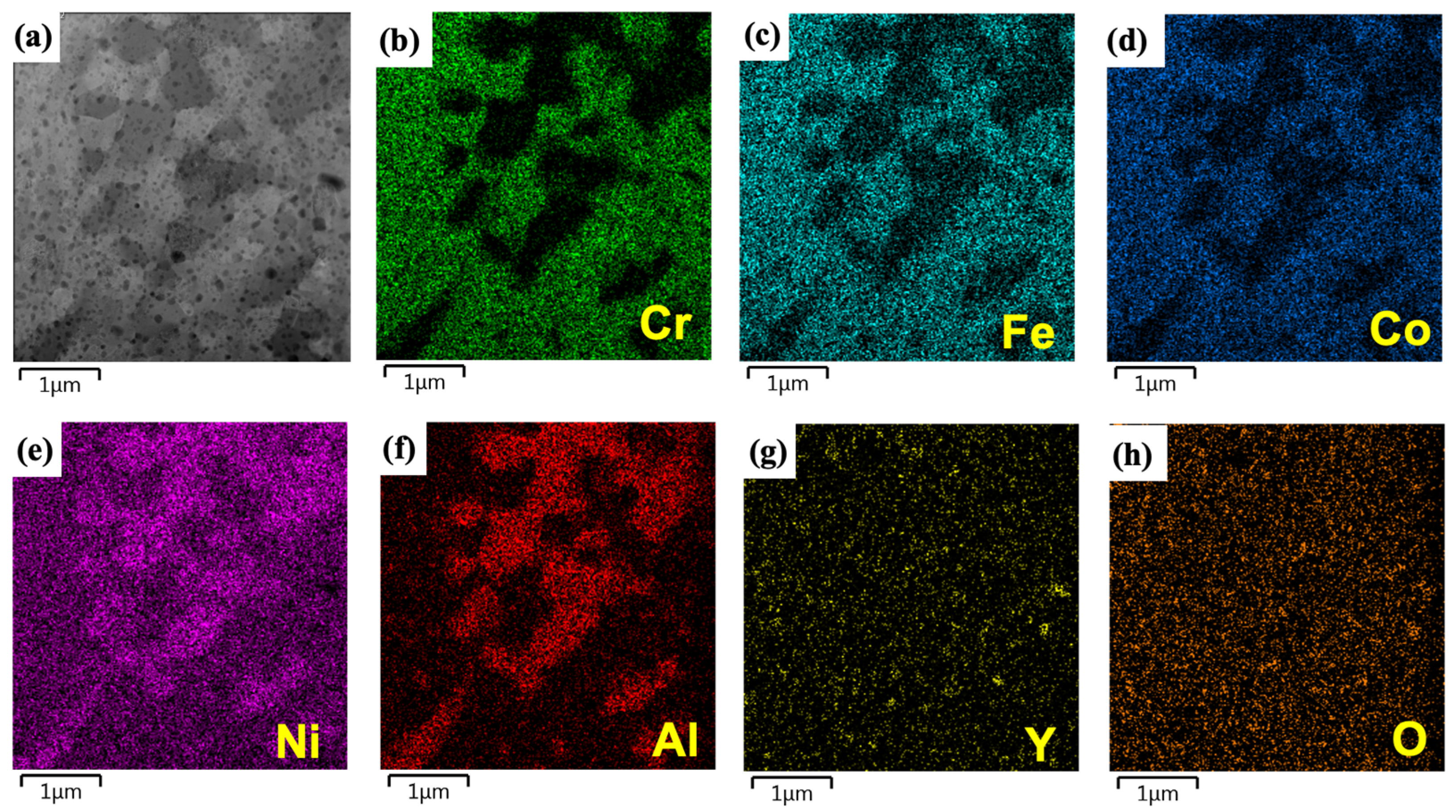
A high-resolution EDS map was obtained from the alloy, as shown in
Figure 10. The HR-EDS analysis can identify the dual-phase structure of FCC/BCC. The Ni and Al concentrate more in the ordered BCC B2 phase, while the FCC phase is enriched in Cr, Fe, and Co. It should be mentioned that some nano-Y
2O
3 particles have been found in the microstructure according to the high intensity of Y and O maps, as shown in
Figure 9.
3.3.3. XRD Analysis
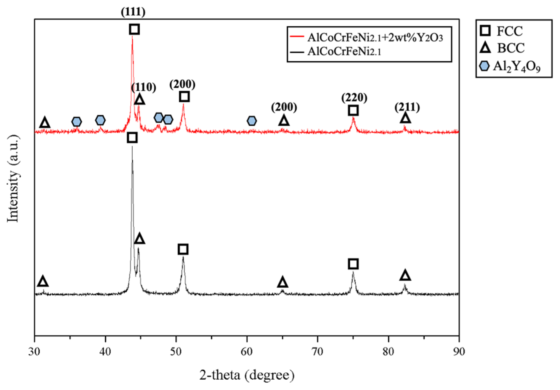
Figure 11 displays the XRD patterns of the bulk model alloys, and it reveals that the alloys are mainly composed of FCC and BCC solid solution phases. The intensity of the peaks associated with the FCC phase is higher than those of the BCC phase, consistent with the investigation of the volume fraction of the model alloys given in
Table 2 (FCC: ~60%; BCC: ~40%). Furthermore, the Al-Y-O oxide phase was detected in the XRD pattern of the sample with Y
2O
3 oxide doping, which can be associated with the Al-rich phases observed in SEM images, see
Figure 6b,c.
3.3.4. Hardness
Figure 12 demonstrates the hardness of the model coatings and bulk materials under various conditions. The coating samples without annealing treatment exhibit higher hardness than those subjected to heat treatment at 1050 °C. This phenomenon can be ascribed to the influence of the microstructure and processing on the mechanical properties of the coatings. Coatings with a nanostructured microstructure and the accumulation of work hardening can be achieved after the mechanical alloying process. A further annealing treatment of the coatings can cause grain growth and a reduction in crystal defects, lowering the material’s hardness. Moreover, the coatings with added yttria dispersoids can have a high hardness value. This suggests that yttria addition serves as a reinforcement phase, enhancing the material’s mechanical properties [
30]. Yttria is essential in inhibiting the dislocation movement by strengthening dispersion.
On the other hand, the hardness results also indicate that a lower hardness was obtained in the bulk alloys compared to the coating materials. This is attributed to a high work hardening density that was created by excessive cold welding between the coating and substrate during ball milling, allowing the coating to approach a higher hardness even after annealing treatment [
30]. It should also be noted that the hardness variation in the bulk alloys is relatively small, indicating better homogeneity in the microstructure. Furthermore, rapid atomic diffusion and grain growth during the high-temperature sintering process can reduce the residual stress in the bulk materials after ball milling, resulting in good phase stability with a uniform composition. It is evident that a stable and uniform microstructure of the dual phase was obtained in bulk materials.
3.3.5. Compression Tests
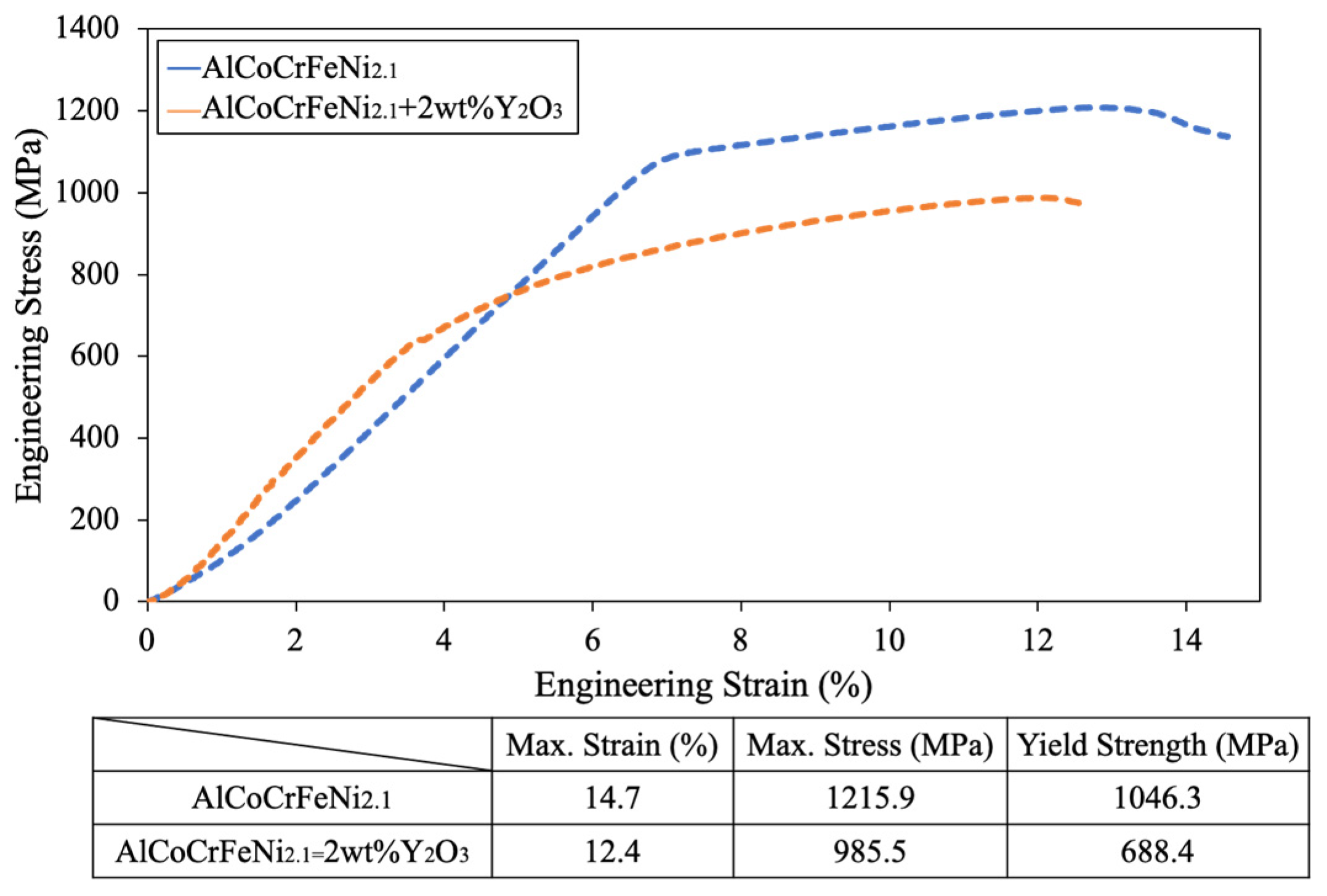
Figure 13 presents the stress–strain curves obtained from compression testing of the bulk materials. It reveals that the maximum engineering stress for the AlCoCrFeNi
2.1 alloy is 1215 MPa, with a yield strength of 1046 MPa, which is higher than that of the Y
2O
3 sample (σ
cu = 1046 MPa, σ
cy = 688 MPa). It recommends that the addition of yttria leads to the generation of numerous pores occupied by Al-Y-O oxides, further causing the increased brittleness in the model alloy. On the other hand, both the model alloys have a low engineering strain value of 12%~14%, which reveals the brittle behavior of the materials.
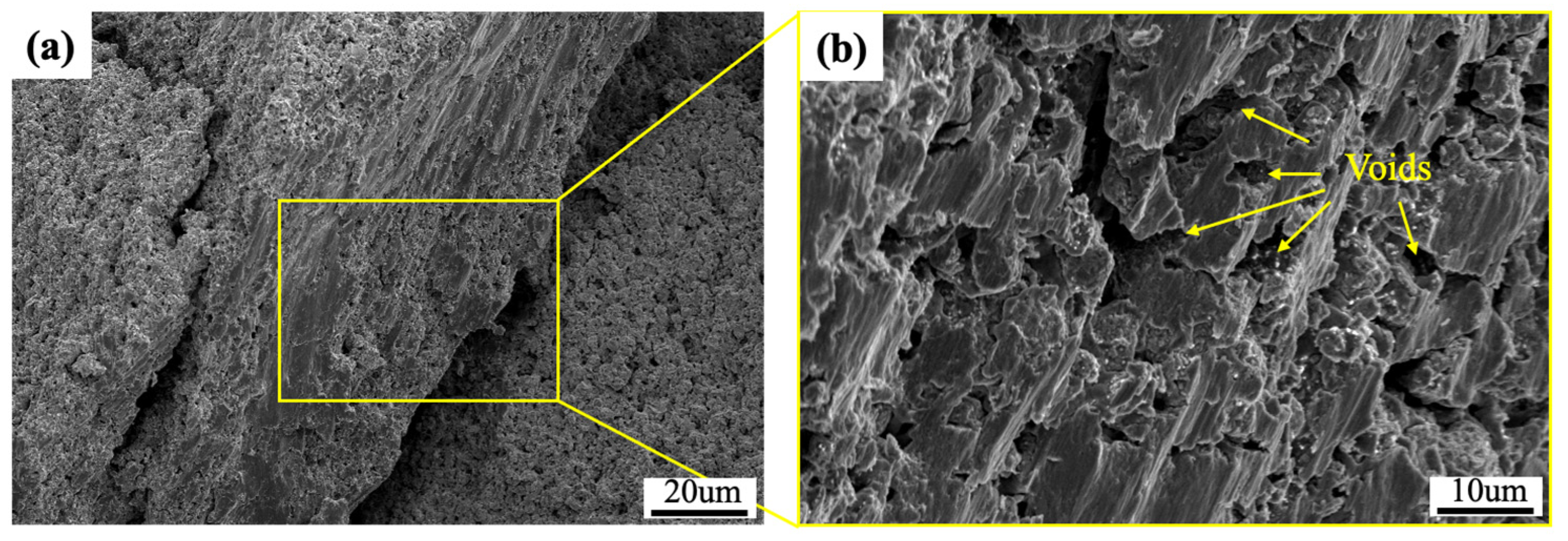
Figure 14 illustrates the fracture surfaces of the Y
2O
3 addition sample after compression testing. Typical splitting patterns can be observed on the fracture surface, indicating a brittle fracture behavior. A number of Al-Y-O pores were also observed in the fracture surfaces, which can also result in the degradation of the mechanical properties of the bulk model alloys.
4. Conclusions
In this study, AlCoCrFeNi2.1 coatings and bulk materials prepared by mechanical alloying were investigated. The XRD patterns of the material powders show that a dual phase (FCC/BCC) was obtained after 16 h of milling. The results can be related to the microstructure development of coatings during ball milling. The coating with 4 h of milling had a laminar structure and a Ni-rich phase. The microstructure of the coating was progressively refined and became more uniform at the final stage of milling. The following observations were made in the coatings further subjected to annealing treatment. Firstly, the formation of Cr-rich phases was found, which could be attributed to the imbalanced cold welding and fracturing induced by the accumulation of stored energy during mechanical alloying between the coating and the substrate. Secondly, Al-rich phases were formed at the coating–substrate interface in the annealed coating with added yttria due to the formation of Al-Y-O oxides. The depletion of Al from the coating can impede the formability of the AlNi phase. On the other hand, the bulk materials were subjected to compaction and high-temperature sintering processes and thus showed good microstructure homogeneity and a uniform composition. The materials with the Y2O3 addition have a higher hardness, which can be associated with the strengthening effect on the microstructure. However, the presence of oxide dispersoids can cause the embrittlement of materials due to the formation of Al-Y-O oxide pores, resulting in the degradation of the mechanical properties of the materials.
Author Contributions
Conceptualization, C.-L.C.; methodology, C.-L.C.; formal analysis, C.-L.C. and F.-Y.H.; investigation, F.-Y.H.; resources, C.-L.C.; writing—preparation, C.-L.C. and F.-Y.H.; writing—editing, C.-L.C.; funding acquisition, C.-L.C. All authors have read and agreed to the published version of the manuscript.
Funding
This research was funded by the National Science and Technology Council (NSTC) of Taiwan under the grant 112-2221-E-259-005-MY3.
Institutional Review Board Statement
Not applicable.
Informed Consent Statement
Not applicable.
Data Availability Statement
Data are contained within the article.
Conflicts of Interest
The authors declare no conflicts of interest. The funders had no role in the design of this study; in the collection, analyses, or interpretation of data; in the writing of this manuscript, and in the decision to publish the results.
References
- Zhang, Y.; Zuo, T.T.; Tang, Z.; Gao, M.C.; Dahmen, K.A.; Liaw, P.K.; Lu, Z.P. Microstructures and properties of high-entropy alloys. Prog. Mater. Sci. 2014, 61, 1–93. [Google Scholar] [CrossRef]
- Miracle, D.B.; Senkov, O.N. A critical review of high entropy alloys and related concepts. Acta Mater. 2017, 122, 448–511. [Google Scholar] [CrossRef]
- He, J.Y.; Liu, W.H.; Wang, H.; Wu, Y.; Liu, X.J.; Nieh, T.G.; Lu, Z.P. Effects of Al addition on structural evolution and tensile properties of the FeCoNiCrMn high-entropy alloy system. Acta Mater. 2014, 62, 105–113. [Google Scholar] [CrossRef]
- Xian, X.; Zhong, Z.H.; Lin, L.J.; Zhu, Z.X.; Chen, C.; Wu, Y.C. Tailoring strength and ductility of high-entropy CrMnFeCoNi alloy by adding Al. Rare Met. 2018, 41, 1015–1021. [Google Scholar] [CrossRef]
- Kumar, J.; Kumar, N.; Das, S.; Gurao, N.P.; Biswas, K. Effect of Al addition on the microstructural evolution of equiatomic CoCrFeMnNi alloy. Trans. Indian Inst. Met. 2018, 71, 2749–2758. [Google Scholar] [CrossRef]
- Lu, Y.; Gao, X.; Jiang, L.; Chen, Z.; Wang, T.; Jie, J.; Li, T. Directly cast bulk eutectic and near-eutectic high entropy alloys with balanced strength and ductility in a wide temperature range. Acta Mater. 2017, 124, 143–150. [Google Scholar] [CrossRef]
- Lu, Y.; Dong, Y.; Guo, S.; Jiang, L.; Kang, H.; Wang, T.; Li, T. A promising new class of high-temperature alloys: Eutectic high-entropy alloys. Sci. Rep. 2014, 4, 6200. [Google Scholar] [CrossRef] [PubMed]
- Shafiei, A. Design of Eutectic High Entropy Alloys in Al–Co–Cr–Fe–Ni System. Met. Mater. Int. 2021, 27, 127–138. [Google Scholar] [CrossRef]
- Lu, Y.; Jiang, H.; Guo, S.; Wang, T.; Cao, Z.; Li, T. A new strategy to design eutectic high-entropy alloys using mixing enthalpy. Intermetallics 2017, 91, 124–128. [Google Scholar] [CrossRef]
- Li, Z.; Ji, Y.; Ye, Q.; Yang, B. An AlCoCrFeNi2.1 high-entropy alloy coating with uniform microstructure and high hardness. Mater. Lett. 2023, 348, 134636. [Google Scholar]
- Zhang, L.; Ji, Y.; Yang, B. Thermal Stability and Hot Corrosion Performance of the AlCoCrFeNi2.1 High-Entropy Alloy Coating by Laser Cladding. Mater. 2023, 16, 5747. [Google Scholar] [CrossRef] [PubMed]
- Wang, R.; Zhang, K.C.D.; Wu, X. Evolution of microstructure, mechanical and corrosion properties of AlCoCrFeNi high-entropy alloy prepared by direct laser fabrication. J. Alloys Compd. 2017, 694, 971–981. [Google Scholar] [CrossRef]
- Wang, L.; Zhang, F.; Yan, S.; Yu, G.; Chen, J.; He, J.; Yin, F. Microstructure evolution and mechanical properties of atmosphere plasma sprayed AlCoCrFeNi high-entropy alloy coatings under post-annealing. J. Alloys Compd. 2021, 872, 159607. [Google Scholar] [CrossRef]
- Fan, Q.; Chen, C.; Fan, C.; Liu, Z.; Cai, C.; Lin, S.; Yang, C. AlCoCrFeNi high-entropy alloy coatings prepared by gas tungsten arc cladding-Microstructure, mechanical and corrosion properties. Intermetallics 2021, 138, 107337. [Google Scholar] [CrossRef]
- Zadorozhnyy, V.; Kaloshkin, S.; Kaevitser, E.; Romankov, S. Coating of metals with intermetallics by mechanical alloying. J. Alloys Compd. 2011, 509, S507–S509. [Google Scholar] [CrossRef]
- Chen, C.L.; Supinator. Microstructure and mechanical properties of AlCuNiFeCr high entropy alloy coatings by mechanical alloying. Surf. Coat. Technol. 2020, 386, 125443. [Google Scholar] [CrossRef]
- Chen, C.L.; Sutrisna. Influence of V and Heat Treatment on Characteristics of WMoNbTaV Refractory High-Entropy Alloy Coatings by Mechanical Alloying. Coatings 2021, 11, 265. [Google Scholar]
- Romankov, S.; Sha, W.; Kaloshkin, S.D.; Kaevitser, K. Fabrication of Ti–Al coatings by mechanical alloying method. Surf. Coat. Technol. 2006, 201, 3235–3245. [Google Scholar] [CrossRef]
- Tian, Y.; Lu, C.; Shen, Y.; Feng, X. Microstructure and corrosion property of CrMnFeCoNi high entropy alloy coating on Q235 substrate via mechanical alloying method. Surf. Interfaces 2019, 15, 135–140. [Google Scholar] [CrossRef]
- Yang, C.; Jing, C.; Fu, T.; Lin, T.; Guo, W.; Liu, N. Effect of CeO2 on the microstructure and properties of AlCoCrFeNi2.1 laser cladding coatings. J. Alloys Compd. 2023, 976, 172948. [Google Scholar] [CrossRef]
- Lu, Y.; Dong, Y.; Jiang, H.; Wang, Z.; Cao, Z.; Guo, S.; Liaw, P.K. Promising properties and future trend of eutectic high entropy alloys. Scr. Mater. 2020, 187, 202–209. [Google Scholar] [CrossRef]
- Dong, Y.; Chen, S.; Wang, J.; Jin, K. Research progress in multi-principal element alloys containing coherent BCC/B2 structure. J. Mater. Eng. 2021, 49, 1–9. [Google Scholar]
- Guo, S.; Liu, C.T. Phase stability in high entropy alloys: Formation of solid-solution phase or amorphous phase. Prog. Nat. Sci. Mater. Int. 2011, 21, 433–446. [Google Scholar] [CrossRef]
- Takeuchi, A.; Inoue, A. Calculations of Mixing Enthalpy and Mismatch Entropy for Ternary Amorphous Alloys. Mater. Trans. 2000, 41, 1372–1378. [Google Scholar] [CrossRef]
- Reverte, E.; Keller, C.; Calvo-Dahlborg, M.; Alcalá, G.; Campos, M.; Cornide, J. Effect of Y2O3 addition on the microstructure and mechanical properties of an Al1.8CoCrCu0.5FeNi BCC HEA. J. Alloys Compd. 2023, 960, 170647. [Google Scholar] [CrossRef]
- Ma, B.; Hishinuma, Y.; Noto, H.; Shimada, Y.; Muroga, T. Development of Y2O3 dispersion strengthened Cu alloy using Cu6Y and Cu2O addition through the MA-HIP process. Fusion Eng. Des. 2020, 161, 112045. [Google Scholar] [CrossRef]
- Kenel, C.; De Luca, A.; Joglekar, S.S.; Leinenbach, C.; Dunand, D.C. Evolution of Y2O3 dispersoids during laser powder bed fusion of oxide dispersion strengthened Ni-Cr-Al-Ti γ/γ’ superalloy. Addit. Manuf. 2021, 47, 102224. [Google Scholar] [CrossRef]
- Manzoni, A.; Daoud, H.; Völkl, R.; Glatzel, U.; Wanderka, N. Phase separation in equiatomic AlCoCrFeNi high-entropy alloy. Ultramicroscopy 2013, 132, 212–215. [Google Scholar] [CrossRef] [PubMed]
- Khan, T.Z.; Kirk, T.; Vazquez, G.; Singh, P.; Smirnov, A.V.; Johnson, D.D.; Arróyave, R. Towards stacking fault energy engineering in FCC high entropy alloys. Acta Mater. 2022, 224, 117472. [Google Scholar] [CrossRef]
- Suryanarayana, C. Mechanical alloying and milling. Prog. Mater. Sci. 2001, 46, 1–184. [Google Scholar] [CrossRef]
Figure 1.
XRD spectra of the AlCoCrFeNi2.1 powders milled for different milling durations: 0 h, 4 h, 8 h, and 16 h.
Figure 1.
XRD spectra of the AlCoCrFeNi2.1 powders milled for different milling durations: 0 h, 4 h, 8 h, and 16 h.
Figure 2.
XRD spectra of the AlCoCrFeNi2.1 added with 2 wt.% of Y2O3 powder milled for different milling durations: 0 h, 4 h, 8 h, and 16 h.
Figure 2.
XRD spectra of the AlCoCrFeNi2.1 added with 2 wt.% of Y2O3 powder milled for different milling durations: 0 h, 4 h, 8 h, and 16 h.
Figure 3.
SEM images of the AlCoCrFeNi2.1 coatings milled for (a) 4 h, (b) 8 h, and (c) 16 h.
Figure 3.
SEM images of the AlCoCrFeNi2.1 coatings milled for (a) 4 h, (b) 8 h, and (c) 16 h.
Figure 4.
SEM images of the AlCoCrFeNi2.1 with 2 wt.% of Y2O3 coatings milled for (a) 4 h, (b) 8 h, and (c) 16 h.
Figure 4.
SEM images of the AlCoCrFeNi2.1 with 2 wt.% of Y2O3 coatings milled for (a) 4 h, (b) 8 h, and (c) 16 h.
Figure 5.
SEM images of the AlCoCrFeNi2.1 coatings after annealing treatment for (a) 4 h, (b) 8 h, and (c) 16 h of milling.
Figure 5.
SEM images of the AlCoCrFeNi2.1 coatings after annealing treatment for (a) 4 h, (b) 8 h, and (c) 16 h of milling.
Figure 6.
SEM images of the AlCoCrFeNi2.1 with 2 wt.% of Y2O3 coatings after annealing treatment for (a) 4 h, (b) 8 h, and (c) 16 h of milling.
Figure 6.
SEM images of the AlCoCrFeNi2.1 with 2 wt.% of Y2O3 coatings after annealing treatment for (a) 4 h, (b) 8 h, and (c) 16 h of milling.
Figure 7.
SEM images of the sintered bulk materials milled for 16 h: (a) AlCoCrFeNi2.1 and (b) AlCoCrFeNi2.1 with 2 wt.% of Y2O3.
Figure 7.
SEM images of the sintered bulk materials milled for 16 h: (a) AlCoCrFeNi2.1 and (b) AlCoCrFeNi2.1 with 2 wt.% of Y2O3.
Figure 8.
TEM investigations of the bulk AlCoCrFeNi2.1 + 2 wt.% Y2O3: (a) TEM bright-field image and the SAD patterns corresponding to (b) point “I” and (c) point “II”.
Figure 8.
TEM investigations of the bulk AlCoCrFeNi2.1 + 2 wt.% Y2O3: (a) TEM bright-field image and the SAD patterns corresponding to (b) point “I” and (c) point “II”.
Figure 9.
TEM investigation of the twinned structure in FCC phase.
Figure 9.
TEM investigation of the twinned structure in FCC phase.
Figure 10.
TEM-EDS mapping of the bulk AlCoCrFeNi2.1 + 2 wt.% Y2O3: (a) SEM image, (b) Cr map, (c) Fe map, (d) Co map, (e) Ni map, (f) Al map, (g) Y map, and (h) O map.
Figure 10.
TEM-EDS mapping of the bulk AlCoCrFeNi2.1 + 2 wt.% Y2O3: (a) SEM image, (b) Cr map, (c) Fe map, (d) Co map, (e) Ni map, (f) Al map, (g) Y map, and (h) O map.
Figure 11.
XRD spectra of the sintered bulk EHEAs.
Figure 11.
XRD spectra of the sintered bulk EHEAs.
Figure 12.
The microhardness of the model coatings and sintered bulk materials.
Figure 12.
The microhardness of the model coatings and sintered bulk materials.
Figure 13.
Compressive engineering stress–strain curves of the sintered bulk materials.
Figure 13.
Compressive engineering stress–strain curves of the sintered bulk materials.
Figure 14.
Fracture surfaces of the bulk AlCoCrFeNi2.1 + 2 wt.% Y2O3.
Figure 14.
Fracture surfaces of the bulk AlCoCrFeNi2.1 + 2 wt.% Y2O3.
| At.% | O | Al | Cr | Fe | Co | Ni | Phase |
|---|
| A | - | - | - | 2.70 | - | 97.30 | Ni-rich |
| B | - | 23.13 | 14.09 | 12.42 | 14.19 | 36.16 | AlNi |
| C | 7.19 | 15.77 | 14.23 | 16.46 | 15.74 | 30.61 | CoCrFe |
| D | - | 4.71 | 3.19 | 38.25 | 12.46 | 16.39 | Interphase |
| E | - | 7.34 | 20.69 | 32.96 | 15.65 | 23.36 | CoCrFe |
| F | - | 54.85 | 8.88 | 12.27 | 5.19 | 9.22 | Al-rich |
| G | - | - | 82.18 | 17.82 | - | - | Cr-rich |
| H | 6.34 | 29.31 | 1.94 | 12.63 | 12.29 | 37.48 | AlNi |
Table 2.
Volume fractions of different phases in the bulk model materials.
Table 2.
Volume fractions of different phases in the bulk model materials.
| Phase | AlCoCrFeNi2.1 | AlCoCrFeNi2.1+2wt%Y2O3 |
|---|
| Ave. Particle Size (µm) | Vol. Fraction (%) | Ave. Particle Size (µm) | Vol. Fraction (%) |
|---|
| CrFeCoNi (FCC) | 4.14 | 54.73 | 3.29 | 59.27 |
| AlNi (BCC) | 0.40 | 37.11 | 0.34 | 36.02 |
| Pore/Oxide | - | - | 0.22 | 5.55 |
| Disclaimer/Publisher’s Note: The statements, opinions and data contained in all publications are solely those of the individual author(s) and contributor(s) and not of MDPI and/or the editor(s). MDPI and/or the editor(s) disclaim responsibility for any injury to people or property resulting from any ideas, methods, instructions or products referred to in the content. |
© 2024 by the authors. Licensee MDPI, Basel, Switzerland. This article is an open access article distributed under the terms and conditions of the Creative Commons Attribution (CC BY) license (https://creativecommons.org/licenses/by/4.0/).


