Abstract
High-carbon nano bainitic steel is currently a hot research topic. The effect of the matrix’s carbon content and carbon atom distribution on the toughness of high-silicon, high-carbon bainitic steel is studied. The microstructure under an incomplete austenitization process consists of undissolved carbides, bainitic ferrite, and retained austenite. Using this process, the carbon content in bainitic ferrite is relatively low. Under the complete austenitization process, the carbon content in the bainite ferrite in the sample is high, and there is more retained austenite in the blocky type. The sample exhibits high impact toughness under an incomplete austenitization process, which is mainly affected by the low carbon content of bainite ferrite, high coordination ability of retained austenite, and high interface density of microstructure. The EBSD results show that the crack easily propagates between parallel bainite laths with low interface density compared with the high interface density perpendicular to the laths.
1. Introduction
Bainitic steel has been widely studied owing to its high strength and toughness and used in components such as bearings, gears, wear plates, wheels, etc. [1,2,3,4]. It has been found that high-carbon bainitic steel can be heat-treated to obtain a bainite microstructure with a nanometer size, and this high-carbon bainitic steel can be used to manufacture high-end bearings, which have better wear and fatigue resistance than the traditional martensitic bearing steel [1,5]. However, there are more factors that control toughness in high-carbon bainitic steels. For example, for the same size and type of sample, the impact toughness of high-carbon bainitic steels under unnotched conditions is increased by 50 percent compared to that of conventional martensitic bearing steels [6]. The impact toughness of high-carbon bainitic steels is significantly reduced to 4–7 J under notched conditions [7]. From this, it can be found that the research on the impact toughness of high-carbon bainitic steels is meaningful.
At present, research has been conducted on the toughness control mechanism of bainitic steel. All measures are reflected in regulating the microstructure. Lu et al. found that the pre-cold deformation of high-carbon bainitic steel could reduce its martensite initiation temperature; the impact toughness of the sample after 30% pre cold working deformation reached 87 J·cm−2, which was much higher than that of the sample obtained by the conventional quenching and tempering heat-treatment process [8]. This is mainly attributed to the formation of a dual-phase nano martensite–bainite structure and thin-film-retained austenite. In the study by Chakraborty et al., pre-cold deformation was combined with bainitic isothermal quenching through a heat treatment process design, and the austenite grains were refined through pre-cold deformation, thereby further improving the impact toughness of high-carbon bainitic steel [9]. Li et al. found that a dual-phase structure containing both martensite and bainite could be obtained by simply using preformed martensite and bainite isothermal quenching without pre-cold deformation, and the impact toughness of the tested steel reached a great value, simplifying the experimental steps [10]. Kumar and Singh found that as the isothermal quenching temperature of bainite decreased, the bainite size gradually refined, and the strength of high-carbon bainite steel increased sharply [11]. However, the impact toughness of high-carbon bainite steel decreased. In their other study, it was found that as the isothermal quenching temperature of bainite increased, the impact toughness and fracture toughness of high-carbon bainitic steel both increased [12]. This is because when the isothermal quenching temperature of bainite is high, the elongation of high-carbon bainite steel is higher, and the plastic work absorbed by the sample during the fracture process is greater. In addition, when the isothermal quenching temperature of bainite is high, high-carbon bainite steel has more retained austenite, and some retained austenite consumes more energy through martensitic transformation. In a recent study on high-carbon bainitic steel, Peet et al. found that the combination of toughness and strength can be improved by reducing the original austenite grain size. When the original austenite grain size of high-carbon bainitic steel was refined from 145 µm to 20 µm, it was found that the strength increased by 40%, and the impact toughness more than doubled [13]. Li et al. improved the toughness of high-strength low-alloy steel by refining the original austenite grains, but the contribution of refining the original austenite grains to strength and elongation was relatively limited [14]. Researchers found that when carbide precipitates in martensitic plate, it can increase the toughness of the tested steel; when carbide precipitates in the martensitic plate and original austenite grain boundary, it reduces the toughness of the tested steel, which provides a new idea for increasing the toughness of high-carbon bainitic steel [15].
All of the above have an effect on toughness through the microstructure of the process. Undoubtedly, carbon plays an important role in bainitic steel. For example, a solid solution of carbon in bainitic ferrite increases the strength of bainitic ferrite. The carbon content can increase the yield strength of the retained austenite, affect the mechanical stability of the retained austenite and the morphology, and so on. Therefore, this paper investigates the influence law of carbon distribution in bainitic steel on the impact toughness of high-carbon bainitic steel.
2. Experimental Procedures
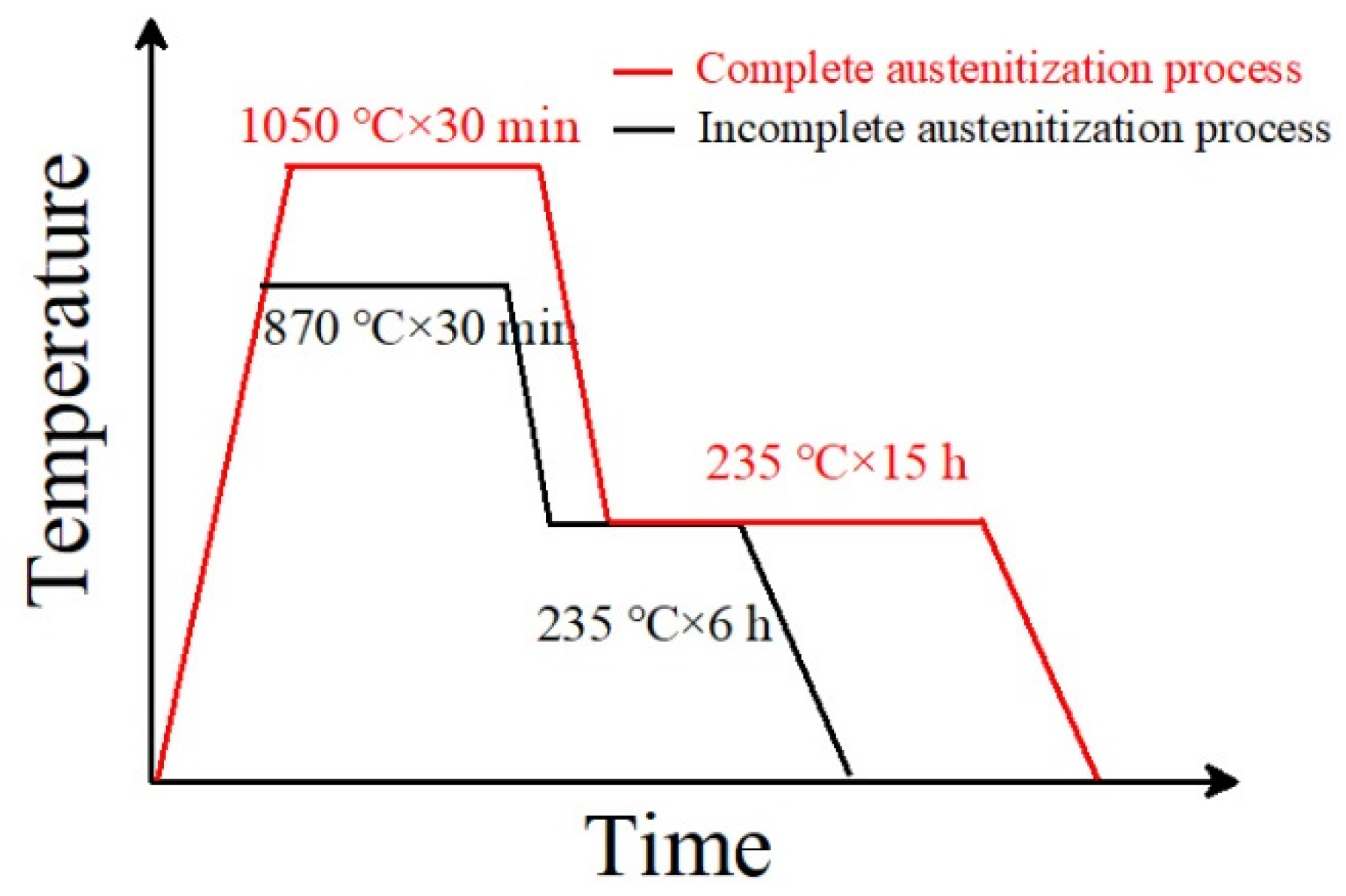
The experimental material composition was 0.89C-0.39Mn-1.43Si-1.55Cr (wt.%). The tested steel state was in a spheroidized annealed state. The Ac1 and Accm temperatures of the tested steel after spheroidizing and annealing were measured using a DIL-402 Dilatometer (Netzsch, Selb, Germany) for thermal expansion phase change. The Ms point and phase transformation kinetics of the tested steels were determined using a DIL-805A/D Dilatometer (TA Instruments, Hüllhorst, Germany) for thermal expansion and phase transformation. The measured Ac1 temperature of the tested steel was 760 °C, the Accm temperature was 805 °C, and the carbide complete dissolution temperature was 930 °C. The tested steel underwent two heat treatment processes. The first retained some undissolved carbides (namely, incomplete austenitization process), and the other dissolved all carbides, namely, a complete austenitization process. For the incomplete austenitization process, the austenitization temperature was 870 °C, the holding time was 30 min, and then a 235 °C isothermal quenching treatment was carried out. For the complete austenitization process, the austenitization temperature was 1050 °C, the holding time as 30 min, and then 235 °C bainite isothermal quenching treatment was carried out. The heat treatment process is shown in Figure 1.
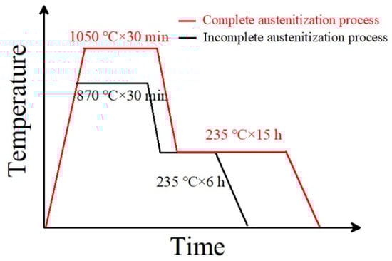
Figure 1.
The heat treatment process of tested steel.
After austenitizing at 870 °C, the Ms point of the tested steel was measured to be 195 °C, and the grain size was about 8 μm. After austenitizing at 1050 °C, the Ms point of the tested steel was measured to be 142 °C, and the grain size was 46 μm. We used software (Thermo-Calc® software, 2020b, Stockholm, Sweden, using the TCFE11 and MOBFE6 databases) to simulate Ms points of the tested steel. The simulation showed that the Ms point of the tested steel under the complete austenitization process was 151.3 °C, which was in good agreement with the Ms point of 142 °C under the complete austenitization process in the tested steel. Therefore, it is believed that the software simulation results were feasible. Further reverse simulation was conducted on the carbon content of the tested steel matrix under the incomplete austenitization process. The Ms point of the tested steel under the incomplete austenitization process was 195 °C, and with a simulation error of 9.3 °C, the simulated Ms point was 204.3 °C, resulting in a matrix carbon content of 0.74 wt.%.
The microstructure characterization and analyses of different treated samples were conducted using a SU-5000 thermal field-emission scanning electron microscope (SEM, Hi-tachi, Tokyo, Japan). SEM samples were etched with 4% nitric acid alcohol solution after grinding and polishing. The EBSD characterization was carried out by an Oxford S9000X (Oxford, UK) electron backscatter diffraction microscope equipped with a SU-5000 scanning electron microscope. The sample was polished and then subjected to final mechanical polishing to remove the stress layer. The EBSD test was set up with an operating voltage of 30 kV, an operating distance of 16 mm, and a scan step of 80 nm. The microstructure of the samples was characterized using a transmission electron microscope (TEM; Thermo Fisher, Waltham, MA, USA). The TEM samples were prepared by twin-jet electropolishing. The electrolyte was 7% perchloric acid and 93% glacial acetic acid, and the voltage and temperature were 28 V and 25 °C, respectively. To analyze the phase composition with different heat treatment processes, the samples were diffracted using an X-ray diffractometer (Rigaku SmartLab, Tokyo, Japan). The radiation target was Co-Kα. The XRD tested was scanned in the range [40°, 130°] with a scanning speed of 2°/min. The retained austenite fraction was calculated using Equation (1):
where is the number of peaks measured, is the integrated intensity of the diffraction peak, and is a material scattering factor. can be interpreted as
where is the structure factor, is the multiple factor, and is the temperature coefficient.
The localized carbon content of the retained austenite and adjacent bainite plates was quantitatively measured with three-dimensional atomic probe tomography (APT, Cameca Instruments LEAP 4000X HR-type, Madison, WI, USA). The LEAP was operated in voltage-pulse mode with a sample temperature of 50 K, a pulse repetition rate of 200 kHz, and a pulse fraction of 0.2. The APT samples were prepared through a site-specific FIB lift-out technique. Image Visualization and Analysis Software version 3.6 was used for 3D reconstruction and composition analyses. The impact sample size was a standard Charpy V-impact sample of 10 mm × 10 mm × 55 mm. Three samples were prepared for each group of tests. The hardness was determined by a Rockwell hardness tester and classified as HRC.
3. Results
3.1. Bainitic Transformation Time
Figure 2 shows the kinetic curves of the isothermal transformation of the tested steel at 235 °C under different processes. It can be seen that under the complete austenitization process, the incubation period of the bainite transformation was longer, and the rate of bainite transformation was lower. This is because the carburize in the sample of the complete austenitization process was fully dissolved in the matrix, and the concentration of carbon atoms in the austenite was relatively high after the sample was completely austenitized. In the bainite transformation gestation stage, carbon atoms moved from the austenite grain boundaries to the austenite crystal diffusion, resulting in a gradual decrease in the concentration of carbon atoms at the austenite grain boundaries. The bainite transformation driving force gradually increased. When the concentration of carbon atoms at the austenite grain boundaries reaches a critical value, at the end of the bainite transformation gestation period, bainite ferrite forms in the austenite grain boundaries at the beginning of nucleation [16].
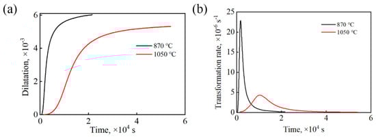
Figure 2.
Bainitic transformation kinetics curves of the tested steels: (a) relationship of expansion and time; (b) bainitic transformation rate curves.
After the complete austenitization treatment of the tested steel, the original undissolved carbides in the matrix dissolves, and the carbon atoms that originally existed in the form of carbides entered the matrix. Therefore, the sample undergoing the complete austenitization treatment processes had a high carbon content in the matrix. However, the bainite transformation requires carbon atom diffusion, and excess carbon atoms are discharged into the surrounding undercooled austenite. The higher carbon concentration of the surrounding undercooled austenite inhibits the process of bainite ferrite discharging carbon atoms to the surrounding undercooled austenite. It is difficult to widen the bainite ferrite plate. In addition, due to the growth in bainite ferrite in a shear manner, the introduction of dislocations and plastic deformation further increase the strength of undercooled austenite, making it difficult for bainite ferrite to undergo shear. The influence of grain size on bainite transformation cannot be ignored. The austenite grain size increases gradually, which reduces the resistance to the growth of bainite ferrite lath. Therefore, a large grain size can accelerate the phase transformation rate [17,18,19]. According to the above analysis, the main reason for the slow bainite transformation rate of the sample under the complete austenitization process was the increase in the matrix carbon content.
3.2. Microstructure and Mechanical Property
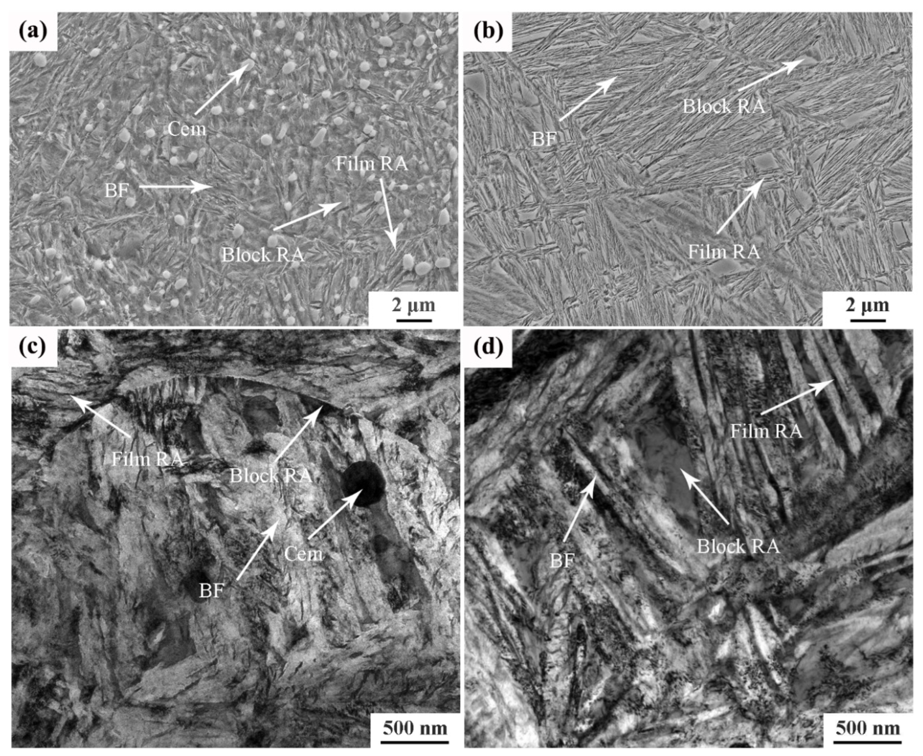
Figure 3 shows the SEM and TEM images of the tested steel after different heat treatment processes. The microstructures of the tested steel after two different heat treatment processes were quite different. Figure 3a,c show the matrix microstructure of the tested steel under the incomplete austenitizing process. The undissolved carbide particles (cementite) are evenly distributed in the matrix, and the bainitic ferrite laths and retained austenite can also be observed. The retained austenite between bainitic ferrite laths was in the form of a film. The retained austenite at the interface of bainitic ferrite laths was irregular and blocky. Figure 3b,d show the bainite microstructure of the tested steel under the complete austenitizing process. Undissolved cementite cannot observed, which means that the undissolved cementite was completely dissolved in the process of complete austenitizing. The length of the bainite ferrite laths in Figure 3b is significantly longer than the microstructure shown in Figure 3a. On the one hand, because the complete austenitizing temperature was high, the original austenite grains coarsened. Therefore, the bainite ferrite laths had a larger growth space in the length direction, and the length of bainite ferrite laths increased. On the other hand, the growth in bainitic ferrite laths under the incomplete austenitizing process was hindered by undissolved cementite; thus, the length of the bainitic ferrite laths was short. Compared to the undissolved process, the distribution angle of the retained austenite in the microstructure obtained by the complete austenitization process was obvious, as shown in Figure 3b. In addition, the bainite microstructure of the tested steel under the complete austenitizing process was finer than that under the incomplete austenitizing process.
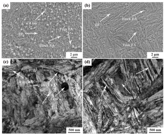
Figure 3.
Microstructure image of different samples subjected to (a) 870 °C: SEM image; (b) 1050 °C: SEM image; (c) 870 °C:TEM image; (d) 1050 °C: TEM image. Note: BF: bainitic ferrite; RA: retained austenite; Cem: cementite.
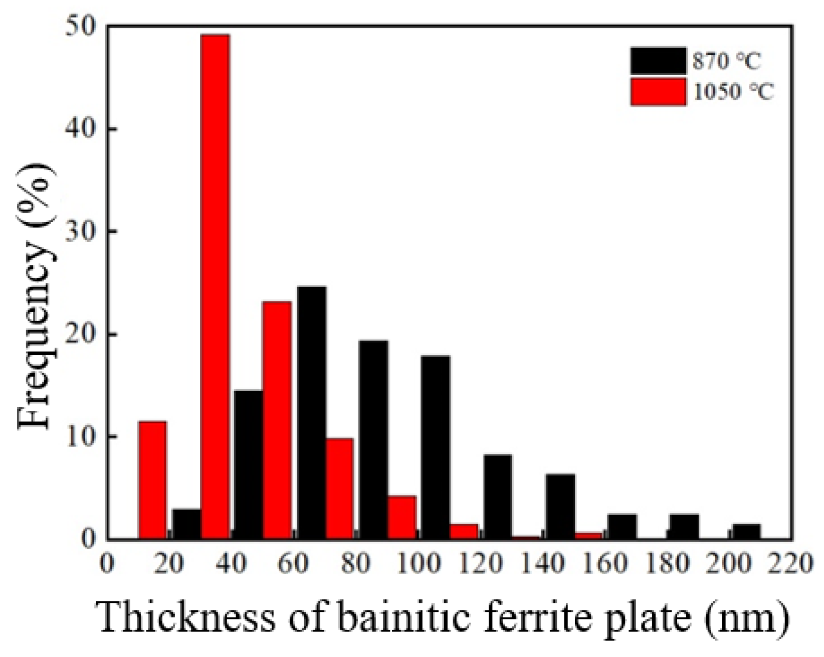
The TEM images under the two processes were analyzed The thickness intercept of the bainite ferrite plates was measured, and the true measured value (tBF) [20] was obtained through the stereo correction formula, as shown in Table 1. Figure 4 depicts the thickness distribution diagram of the bainite ferrite plates after different heat treatment processes for the tested steel. The average thickness of the bainitic ferrite plates of the tested steel under the incomplete austenitizing process was 93.6 nm, which was 41.1 nm under the complete austenitizing process. This shows that the bainite ferrite plates of the sample under the complete austenitizing process were significantly thinner than under the incomplete austenitizing process. Bhadeshia et al. [21] found that the thickness of bainitic ferrite plates is not directly affected by the isothermal temperature, while the strength of undercooled austenite is an important factor affecting the thickness of bainitic ferrite plates. Cornide et al. [22] found that the thickness of bainitic ferrite plates is less affected by the free energy difference, and the strength of undercooled austenite is still an important factor affecting the thickness of bainitic ferrite plates. For the sample after the complete austenitizing process, the undissolved cementite retained by spheroidizing annealing dissolved, and carbon atoms entered the matrix. Thus, the carbon content in the matrix was high. During the subsequent isothermal bainite, due to the higher carbon concentration in the undercooled austenite, the solution strengthening effect was stronger. Therefore, it had higher undercooled austenite strength, and the bainitic ferrite plates were thinner [23].

Table 1.
Microstructure parameters of the tested steels.

Figure 4.
Thickness distribution of bainite ferrite plate of the sample after different processes.
In addition, the film-like retained austenite of the sample under the complete austenitizing process was thicker than that under the incomplete austenitizing process. On the one hand, the increase in strength of the undercooled austenite mentioned above made it difficult to shear the bainite. On the other hand, carbon atom diffusion is required during bainite transformation. The sample under the complete austenitizing process had a higher matrix carbon content. The process of discharging excess carbon atoms into the surrounding undercooled austenite during bainite broadening was suppressed. These factors worked together to cause a thicker film-like retained austenite in the sample under the complete austenitization process.
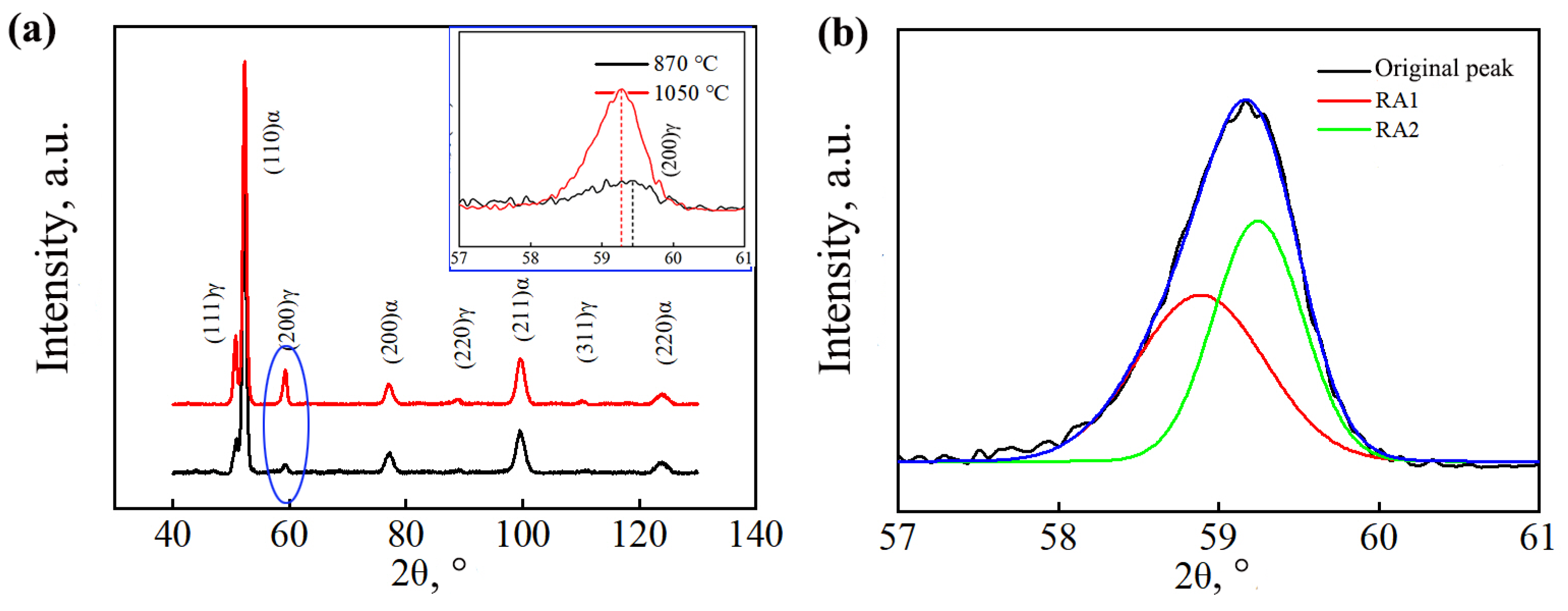
Figure 5 shows the XRD diffraction patterns of the tested steel after different heat treatment processes. The RA content of different samples was calculated using Equation (1). Table 1 shows the volume fraction of the retained austenite and the carbon content of the sample. The sample under the complete austenitization process possessed a higher retained austenite carbon content than the sample under the incomplete austenitization process. In addition, under the complete austenitization process, the (200) γ peak of the sample shifted to the left, indicating a higher carbon content in the retained austenite.
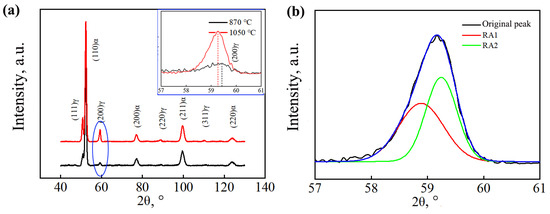
Figure 5.
XRD curves: (a) diffraction pattern (illustration; (200)γ peak); (b) schematic diagram of peak division.
The sample under the complete austenitizing process had a higher volume fraction of retained austenite than that under the incomplete austenitizing process, as shown in Table 1. This is because the carbon content of undercooled austenite was higher for the complete austenitizing process. It led to a higher strength of the undercooled austenite. Then, the shear resistance of bainite was greater, and bainite shear was difficult. At the same time, the higher carbon content of the undercooled austenite increased its stability. Therefore, much undercooled austenite was retained.
There are two morphologies of retained austenite: thin film-like retained austenite and blocky retained austenite. The carbon content of blocky retained austenite is relatively lower, leading to lower stability. Blocky retained austenite transforms into martensite easily under external forces, while the unstable interface between the newly generated hard-phase martensite and the surrounding untransformed retained austenite is prone to stress concentration, which promotes crack nucleation and propagation [24,25]. XRD testing cannot directly distinguish between film-like and blocky retained austenite. The aforementioned XRD calculation can only obtain the sum of the volume fractions of film-like retained austenite and blocky retained austenite. Therefore, the Gaussian multipeak fitting method was used to fit and partition the diffraction peaks of (200) γ; two different forms of retained austenite subpeaks were obtained, as shown in Figure 5b. Small-angle RA1 had high lattice constants and a high carbon content (red curve), while large-angle RA2 had lower lattice constants and a lower carbon content (green curve). The volume fraction and carbon content in the different kinds of retained austenite were calculated [26], and the results are shown in Table 1. The calculation results show that the sample under the complete austenitizing process had a higher volume fraction and proportion of blocky retained austenite than that under the incomplete austenitizing process. This was mainly because the sample under the complete austenitization process had a higher matrix carbon content.
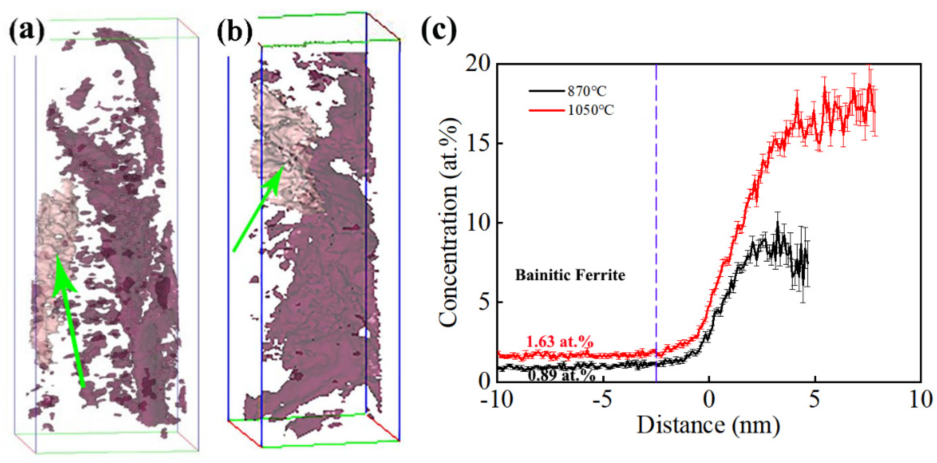
Three-dimensional atom probe tomography technology can analyze the distribution of elements in materials at the atomic scale [27]. The distribution of carbon atoms was characterized using 3D-APT analysis, as shown in Figure 6. It can be observed that the distribution of carbon atoms was uneven, with the presence of carbon-poor and carbon-rich regions. This phenomenon was consistent between the samples of the two processes. To further analyze the distribution pattern of carbon atoms in the tested steel, a carbon atom concentration of 3.5 at.% was set, and the areas with the same carbon atom concentration were connected to form a carbon atom concentration surface of 3.5 at.%. The carbon atom distribution of the samples under different processes was analyzed as follows.
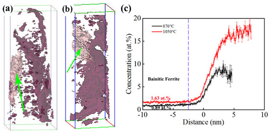
Figure 6.
Distribution of solute atoms in bainite microstructures under 3.5% C isosurface: (a) 870 °C and (b) 1050 °C; (c) carbon atom distribution in the area indicated by the arrow with distance.
For the carbon atoms in the sample under the incomplete austenitization process, the 3.5 at.% equiconcentration surface of the carbon atom shown by the arrow was selected for analysis. The results are shown in Figure 6c, where the zero position is located on the equiconcentration surface of the 3.5 at.% carbon atom. When the distance is negative, it represents an atomic percentage of carbon elements outside the equiconcentration surface of the carbon atom. When the distance is positive, it represents an atomic percentage of carbon element inside the equiconcentration surface of the carbon atom. The carbon content stabilized at around 0.89 at.% in the region of −10~−2.45 nm, and carbon atoms were enriched in the region of −2.45~4.85 nm. The closer the region to the center, the higher the carbon atom concentration and the greater the degree of carbon atom enrichment. The carbon content reached its maximum value of 10.10 at.% at 3.25 nm.
The sample after the complete austenitization process was constructed on a 3.5 at.% carbon atom equiconcentration surface, as shown in Figure 6b. We performed carbon element distribution analysis on the 3.5 at.% carbon atom equiconcentration surface shown by the arrow in Figure 6c. Carbon atom segregation occurred in the target carbon atom concentration plane, with a minimum carbon content of 1.63 at.% and the highest carbon content of 18.77 at.% at 7.95 nm. Research has shown that the carbon-poor area is bainite ferrite, while the carbon-rich zone is retained austenite [28,29]. Within the range of −3 nm, the concentration of carbon atoms remained basically unchanged from the outside to −10 nm, while the concentration of carbon atoms increased with distance from the inside to the center of the carbon atom concentration plane. The corresponding carbon atom concentration at −10 nm was the carbon atom concentration of bainite ferrite. The carbon content of bainite ferrite in the sample under the incomplete austenitizing process was 0.89 at.%, and the carbon content of bainite ferrite in the tested steel under the complete austenitizing process was 1.63 at.%. This indicates that the carbon content had a higher value in bainitic ferrite after the complete austenitizing process content than after the incomplete austenitizing process. This was caused by the high carbon content in the matrix and the limited carbon diffusion during the bainite transformation process.
Table 2 shows the hardness and impact toughness of the tested steel under different heat treatment processes. The difference in hardness between the two was not significant. There were significant differences in toughness. The toughness of the sample treated with incomplete austenitization was twice that of the sample treated with complete austenitization.
Table 2.
Hardness and impact toughness of the tested steel under different heat treatment processes.
4. Analysis and Discussion
4.1. The Influence of Carbon Distribution on Toughness
Bainitic microstructures with different matrix carbon contents were obtained by subjecting the tested steels to complete and incomplete austenitization. The matrix carbon content of the fully austenitized tested steel was 0.89 wt.%, consistent with the designed composition. For the incomplete austenitization treatment, the tested steel microstructure retained undissolved carbides, and the matrix carbon content was lower. its value according to the simulation calculation was approximately 0.74 wt.%. Combined with the hardness and impact toughness test data of the different heat treatment processes, the large difference in the mechanical properties was affected by the matrix’s carbon content and the microstructure size. In addition, from a macroscopic viewpoint, the carbon content directly affects the toughness of metal materials. A high carbon content generally indicates low toughness.
Bainitic ferrite as the main phase had an important influence on the mechanical properties of the tested steel. According to the APT test results, the carbon content in the bainitic ferrite of the tested steel with a higher matrix carbon content was 1.63 at.%, and the carbon content in the bainitic ferrite of the tested steel with a lower matrix carbon content was 0.89 at.%. This indicates that the matrix carbon content of the tested steel has an effect on the carbon content in bainitic ferrite, i.e., an increase in the former leads to an increase in the carbon content in the latter. An increased carbon content in bainitic ferrite increases its solid-solution strengthening effect. This can reduce the coordinated deformation capacity, make the tested steel more likely to produce stress concentration and thus form microcracks when receiving impact loads, and reduce the impact toughness of the tested steel. When the matrix carbon content of the tested steel was increased, the thickness of the bainitic ferrite plate decreased from 93.6 nm to 41.1 nm. Thus, the sample with a higher matrix carbon content has more phase interfaces, which increases the strength and hardness [30,31]. However, the sample with the lower matrix carbon content had higher hardness, which was mainly due to the presence of a large amount of undissolved carbide in the microstructure. Carbide as a hard phase can significantly increase the hardness of tested steel.
Regarding toughness-controlling factors, retained austenite cannot be ignored. In this study, the volume fraction of retained austenite under the two processes differed greatly, and the sample with a high matrix carbon content exhibited a high volume fraction of retained austenite; notably, its volume fraction of blocky type was twice as large as that of the other process. In addition, it can be clearly observed from the SEM images that the distribution of blocky retained austenite was higher in this process, and the size reached 2 μm. The stability of this type of retained austenite is poor; when subjected to external forces, it is prone to martensitic transformation reducing the impact toughness of the tested steel [32,33,34]. The carbon content of the retained austenite in the sample with a low matrix carbon content was reduced, but the coordinated deformation ability increased the impact toughness of the tested steel. In addition, the presence of undissolved carbide may have a negative impact on the impact toughness of the tested steel, while this adverse effect in the surrounding softer bainitic ferrite and retained austenite is attenuated [35]. The above factors contribute to the higher impact toughness of the tested steel with a lower matrix carbon content.
4.2. The Influence of Interface Density on Toughness
Comparing the microstructures produced with the two processes shown in Figure 7a,b, the microstructure of the tested steel under the fully austenitized process was significantly rougher. The coarsening of the microstructure manifested not only as an increase in the size of the original austenite grains but also as the presence of certain coarsening in the multilayer substructure within the austenite grains, including the packet and block of the bainite [36,37]. The block of bainite is usually considered the smallest unit for regulating the toughness of tested steel, which is related to the characteristics and density of the block interface. Adjacent blocks are often separated by high-angle grain boundaries, which are usually considered an effective way to hinder the propagation of brittle cracks. As the size of the block increases, the density of the high-angle interface is bound to decrease [38,39]. A certain area was randomly selected from the microstructure of the two process samples to observe its interface distribution, as shown in Figure 7c,d. The high-angle grain boundary density of the fully austenitized process tested steel was lower than that of the incomplete austenitized process sample, which was one reason why its toughness was lower than that of the incomplete austenitized process sample.
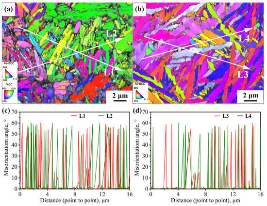
Figure 7.
The distribution of interfaces in microstructure under different processes: (a,c) 870 °C; (b,d) 1050 °C.
4.3. Crack Propagation Path
To investigate the reasons for the differences in the impact toughness of the tested steel, EBSD characterization was performed on the cracks at the longitudinal section of the impact fracture of the tested steel, and the crack propagation mechanism during the failure process of the tested steel was analyzed. The phase composition diagrams of the impact fracture surface of the samples after different heat treatment processes are shown in Figure 8a,d. It can be seen that different austenitizing temperatures had a significant impact on the phase composition of the samples. A large amount of irregularly shaped carbides can be observed in the phase composition diagram of the sample with incomplete austenitization process (yellow part in Figure 8), while the content of thew retained austenite is relatively low. In the phase composition diagram of the fully austenitized sample, it can be seen that even if there was still a lot of retained austenite in the sample after bearing a large impact stress (red part in Figure 8d), no carbide precipitation was observed, which is consistent with the XRD calculation results. This indicates that the fracture mechanism of this sample was brittle fracture, without causing plastic deformation in the sample beyond the cracks.
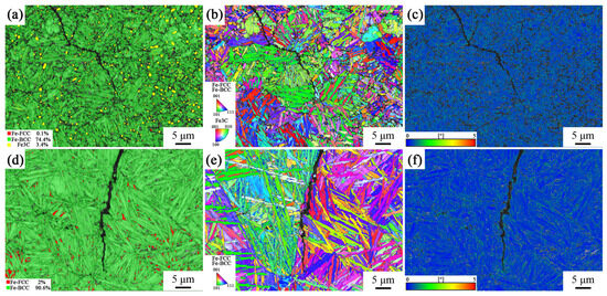
Figure 8.
Phase composition diagram, IPF diagram, and KAM diagram of impact fracture surface of samples under different heat treatment processes: (a–c) 870 °C; (d–f) 1050 °C.
In addition, the grain size of the sample produced with the incomplete austenitization process was relatively small, and the growth direction of bainite ferrite was more disorderly, as shown in Figure 8b,e. This was because its austenitization temperature was low, and the matrix contained insoluble cementite, which hindered grain coarsening and limited the growth space of bainite ferrite. The grain size of the fully austenitized samples was larger, and the bainite ferrite lath was longer. Grain coarsening led to lower toughness of the sample under the complete austenitization process. The smaller grain size in the incomplete austenitizing process made the bainite ferrite lath process more oriented, forcing the cracks to constantly turn to adapt to the crystallographic plane. The sample from the complete austenitization process had larger grains, making it easier for cracks to propagate along a single direction of grain boundaries.
Figure 8c,f depict the KAM map of the samples under the two different processes, and the stress distribution can be observed. The high KAM value of the incomplete austenitized sample located at the interface between the carburized and bainitic matrix structure. This means that when the tested steel was subjected to external forces, stress concentration was prone to occurring at this interface. When the stress concentration reached a certain level, it led to crack nucleation. The high KAM value of complete austenitized sample was mainly located at the interface between the retained austenite and bainitic ferrite lath.
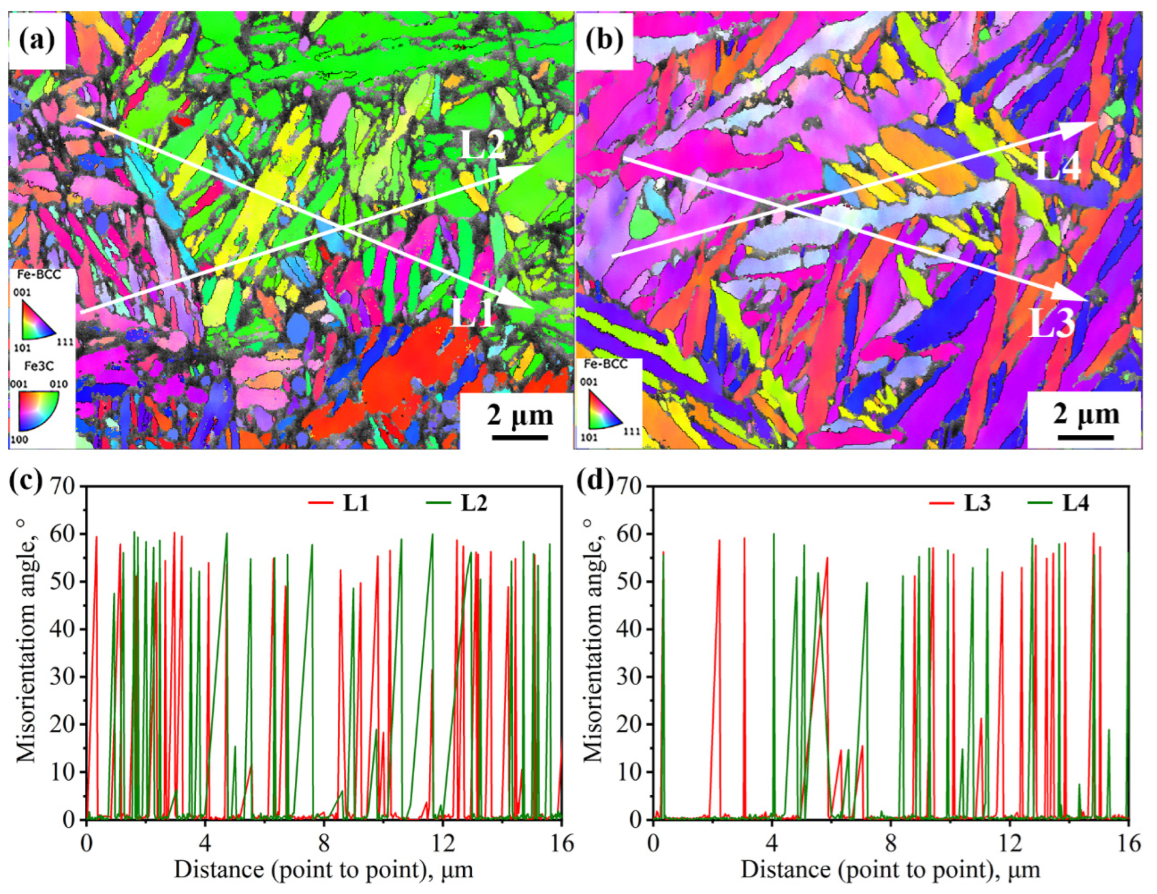
Figure 9 shows two typical regions in the path of impact subcrack extension under the incomplete austenitization process. In both regions, the cracks completely traverse the entire austenite grain. In Grain 1, the cracks extend through the bainite lath, whereas in Grain 2, the cracks advance in the direction of the lath. In fact, there is some connection with the interfacial distribution of the two. For Grain 1, the block size is relatively large, while the morphology of some blocks is approximately isometric. Thus, the difference in the density of high-angle interfaces in all directions within the grain is small, such as in the L1 direction parallel to the lath versus in the L2 direction of the crack through the lath in Figure 9a. In addition, the expansion of impact subcracks is an energy-consuming process, with cracks forming at the beginning of a larger energy; therefore, their ability to pass through the bainite lath and subsequently expand along the austenite grain boundaries is also stronger. For Grain 2, its large-angle interfacial density was significantly higher in the direction perpendicular to the bainite lath (L4) than in the direction parallel to the lath (L3), as shown in Figure 9b. The small hollow arrows in Figure 9b point out two typical regions of crack deflection; i.e., when a brittle crack is deflected to a direction perpendicular to the beam, the extension is strongly impeded by the interface for a short distance and is deflected back to a direction parallel to the beam.
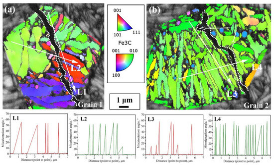
Figure 9.
The propagation path of cracks passing through austenite grains and interface density in different directions under the incomplete austenitization process (a,b).
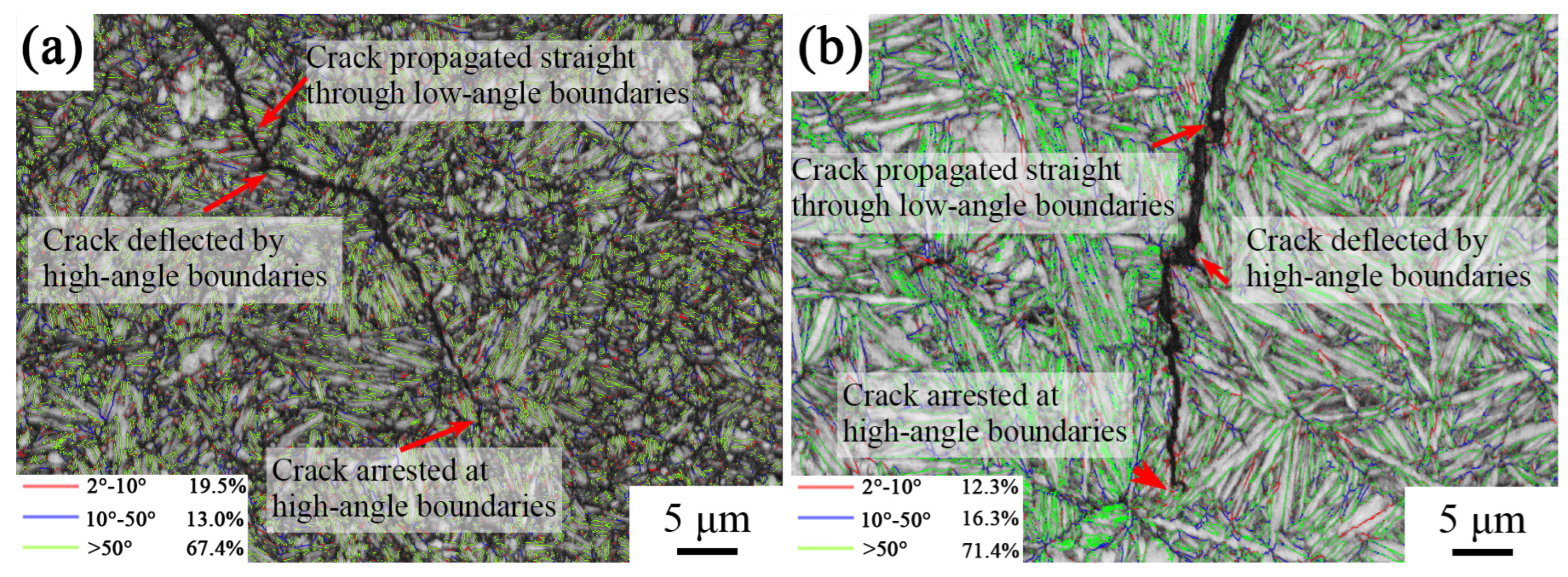
In order to study the influence of interface angle on impact crack extension, the angle distribution of the sample’s longitudinal cross-section interface after different heat treatments was characterized, as shown in Figure 10. The red line represents the distribution of small-angle interfaces of 2°–10°, the blue line represents the large-angle interfaces of 10°–50°, and the green line represents the large-angle interfaces of >50°. The results show that most of the large-angle interfaces between the bainitic ferrite laths were >50°. It can be seen from the figure that the cracks passed through the small-angle interfaces and were deflected or stopped when encountering the large-angle interfaces. The large-angle interfaces had a hindering effect on crack extension, which means that cracks were more likely to extend along the grain than to tear the bainitic ferrite during extension.
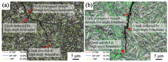
Figure 10.
Distribution of grain boundaries in the longitudinal section of the impact fracture surface of samples under different heat treatment processes: (a) 870 °C; (b) 1050 °C.
5. Conclusions
- 1.
- By adjusting the heat treatment method, the carbon content of the tested steel matrix was reduced from 0.89 wt.% to 0.74 wt.%. After the reduction in the matrix carbon content, the incubation period of bainitic transformation in the tested steel was shortened, and the peak rate of bainite transformation increased.
- 2.
- The microstructure of the tested steel under the complete austenite process was composed of bainitic ferrite and retained austenite. The microstructure of the tested steel under the incomplete austenitization process was composed of bainitic ferrite, retained austenite, and undissolved carbide. The latter organization was significantly coarser.
- 3.
- The decrease in the carbon content in the experimental steel matrix caused a decrease in the carbon content in both the bainitic ferrite and medium. At the same time, the volume fraction of the retained austenite decreased from 19.73% to 9.82%.
- 4.
- The carbon content in the matrix of the samples from the complete austenitization process was higher, and the hardness of the tested steel was 58.1 HRC, which had an impact toughness of 26.2 J/cm2. The carbon content in the matrix of the samples from the incomplete austenitization process was lower, and the hardness of the tested steel was 60.1 HRC, which had an impact toughness of 51.2 J/cm2. The hardness and impact toughness of the tested steels with a higher matrix carbon content were lower than those with a lower matrix carbon content. The composition of microstructure phases, interface density, and angle are important factors affecting toughness.
Author Contributions
Resources, X.L. and Y.L.; Writing—original draft, X.L., Z.D., W.W., Z.Y., F.Z. and Y.L. All authors have read and agreed to the published version of the manuscript.
Funding
This research was funded by the National Key R&D Program of China (2021YFB3703500), the National Natural Science Foundation of China (52001275), Opening Project of State Key Laboratory of Metastable Materials Science and Technology (Yanshan University, No. 202402), and the Science and Technology Project of Hebei Education Department (No. KJZX202203).
Institutional Review Board Statement
Not applicable.
Informed Consent Statement
Not applicable.
Data Availability Statement
Data are contained within the article.
Conflicts of Interest
The authors declare no conflicts of interest.
References
- Zhang, F.C.; Yang, Z.N. Development of and perspective on high-performance nanostructured bainitic bearing steel. Engineering 2019, 5, 319–328. [Google Scholar] [CrossRef]
- Yang, Z.N.; Zhang, F.C.; Ji, Y.L.; Wang, Y.H.; Lv, B.; Wang, M. Notably improved mechanical properties via introducing a short austempering treatment on low-carbon martensite steel. Mater. Sci. Eng. A 2016, 673, 524–529. [Google Scholar] [CrossRef]
- Wei, Z.R.; Wang, W.; Liu, M.; Tian, J.Y.; Guang, X. Comparison of wear performance of bainitic and martensitic structure with similar fracture toughness and hardness at different wear conditions. Wear 2023, 512–513, 204512. [Google Scholar] [CrossRef]
- Liu, Y.R.; Tan, Z.L.; Tian, Y.; Zhu, J.Q.; Zhang, M.; Zhang, M.R.; Zhao, C.H. Temperature-dependent crack induced by microstructure evolution in 20Mn2SiMoCuV bainite wheel steel. Eng. Fail. Anal. 2022, 140, 106593. [Google Scholar] [CrossRef]
- Yang, Z.N.; Zhang, F.C. Nanostructured bainitic bearing steel. ISIJ Int. 2020, 60, 18–30. [Google Scholar] [CrossRef]
- Fielding, L.C.D.; Jones, N.G.; Walsh, J.; Boxel, S.V.; Blackmur, M.S.; Lee, P.D.; Withers, P.J.; Stone, H.J.; Bhadeshia, H.K.D.H. Synchrotron analysis of toughness anomalies in nanostructured bainite. Acta Mater. 2016, 105, 52–58. [Google Scholar] [CrossRef]
- Garcia-Mateo, C.; Caballero, F.G. Ultra-high-strength bainitic steels. ISIJ Int. 2005, 45, 1736–1740. [Google Scholar] [CrossRef]
- Lu, X.H.; Qian, D.S.; Li, W.; Jin, X.J. Enhanced toughness of bearing steel by combining prior cold deformation with martensite pre-quenching and bainite transformation. Mater. Lett. 2019, 234, 5–8. [Google Scholar] [CrossRef]
- Chakraborty, J.; Bhattacharjee, D.; Manna, I. Development of ultrafine bainite + martensite duplex microstructure in SAE 52100 bearing steel by prior cold deformation. Scr. Mater. 2009, 61, 604–607. [Google Scholar] [CrossRef]
- Lan, H.F.; Du, L.X.; Li, Q.; Qiu, C.L.; Li, J.P.; Misra, R.D.K. Improvement of strength-toughness combination in austempered low carbon bainitic steel: The key role of refining prior austenite grain size. J. Alloys Compd. 2017, 710, 702–710. [Google Scholar] [CrossRef]
- Kumar, A.; Singh, A. Improvement of strength-toughness combination in nanostructured bainite. Procedia Struct. Integr. 2018, 13, 548–553. [Google Scholar] [CrossRef]
- Kumar, A.; Singh, A. Toughness dependence of nano-bainite on phase fraction and morphology. Mater. Sci. Eng. A 2018, 729, 439–443. [Google Scholar] [CrossRef]
- Peet, M.J.; Fielding, L.C.D.; Hamedany, A.A.; Rawson, M.; Hill, P.; Bhadeshia, H.K.D.H. Strength and toughness of clean nanostructured bainite. Mater. Sci. Technol. 2017, 33, 1171–1179. [Google Scholar] [CrossRef]
- Li, X.C.; Lu, G.Y.; Wang, Q.C.; Zhao, J.X.; Xie, Z.J.; Misra, R.D.K.; Shang, C.J. The effects of prior austenite grain refinement on strength and toughness of high-strength low-alloy steel. Metals 2022, 12, 28. [Google Scholar] [CrossRef]
- Li, J.; Zhang, C.; Liu, Y. Influence of carbides on the high-temperature tempered martensite embrittlement of martensitic heat-resistant steels. Mater. Sci. Eng. A 2016, 670, 256–263. [Google Scholar] [CrossRef]
- Xu, W.; Huang, M.H.; Wang, J.L.; Shen, C.G.; Zhang, T.Y.; Wang, C.C. Review: Relations Between Metastable Austenite and Fatigue Behavior of Steels. Acta Metall. Sin. 2020, 56, 459–475. [Google Scholar]
- Zhao, H.Z.; Lee, Y.K.; Liu, X.H.; Wang, G.D. Effects of austenite grain size on bainite transformation kinetics in AISI 4340 steel. Trans. Mater. Heat Treat. 2006, 27, 59–62. [Google Scholar]
- Lan, L.Y.; Chang, Z.Y.; Fan, P.H. Exploring the difference in bainite transformation with varying the prior austenite grain size in low carbon steel. Metals 2018, 8, 988. [Google Scholar] [CrossRef]
- Sadahiro, Y.; Hiroyasu, Y.; Katsumi, Y.; Masakazu, N. Effects of the austenite grain size and deformation in the unrecrystallized austenite region on bainite transformation behavior and microstructure. ISIJ Int. 2007, 35, 1020–1026. [Google Scholar]
- He, S.H.; He, B.B.; Zhu, K.Y.; Ding, R.; Chen, H.; Huang, M.X. Revealing the role of dislocations on the stability of retained austenite in a tempered bainite. Scr. Mater. 2019, 168, 23–27. [Google Scholar] [CrossRef]
- Singh, S.B.; Bhadeshia, H.K.D.H. Estimation of bainite plate-thickness in low-alloy steels. Mater. Sci. Eng. A 1998, 245, 72–79. [Google Scholar] [CrossRef]
- Cornide, J.; Garcia-Mateo, C.; Capdevila, C.; Cabllero, F.G. An assessment of the contributing factors to the nanoscale structural refinement of advanced bainitic steels. J. Alloys Compd. 2013, 577, 43–47. [Google Scholar] [CrossRef]
- Garcia-Mateo, C.; Caballero, F.G.; Sourmail, T.; Kuntz, M.; Cornide, J.; Smanio, V.; Elvira, R. Tensile behaviour of a nanocrystalline bainitic steel containing 3wt% silicon. Mater. Sci. Eng. A 2012, 549, 185–192. [Google Scholar] [CrossRef]
- Hu, J.; Li, X.Y.; Meng, Q.W.; Wang, L.Y.; Li, Y.Z.; Xu, W. Tailoring retained austenite and mechanical property improvement in Al–Si–V containing medium Mn steel via direct intercritical rolling. Mater. Sci. Eng. A 2022, 855, 143904. [Google Scholar] [CrossRef]
- Zhang, F.C.; Yang, Z.N. Retained Austenite in Bainitic Steel; Yanshan University Press: Qinhuangdao, China, 2019; pp. 169–170. [Google Scholar]
- Xiong, X.C.; Chen, B.; Huang, M.X.; Wang, J.F.; Wang, L. The effect of morphology on the stability of retained austenite in a quenched and partitioned stee. Scr. Mater. 2013, 68, 321–324. [Google Scholar] [CrossRef]
- Morsdorf, L.; Tasan, C.C.; Ponge, D.; Raabe, D. 3D structural and atomic-scale analysis of lath martensite: Effect of the transformation sequence. Acta Mater. 2015, 95, 366–377. [Google Scholar] [CrossRef]
- Caballero, F.G.; Miller, M.K.; Garcia-Mateo, C. Carbon supersaturation of ferrite in a nanocrystalline bainitic steel. Scr. Mater. 2010, 58, 2338–2343. [Google Scholar] [CrossRef]
- Caballero, F.G.; Miller, M.K.; Babu, S.S.; Garcia-Mateo, C. Atomic scale oobservations of bainite transformation in a high carbon high silicon steel. Acta Mater. 2007, 55, 381–390. [Google Scholar] [CrossRef]
- Tu, X.; Shi, X.; Shan, Y.; Yan, W.; Shi, Q.Q.; Li, Y.F.; Li, C.S.; Yang, K. Tensile deformation damage behavior of a high deformability pipeline steel with a ferrite and bainite microstructure. Mater. Sci. Eng. A 2020, 793, 139889. [Google Scholar] [CrossRef]
- Kondo, S.; Mitsuma, T.; Shibata, N.; Ikuhara, Y. Direct observation of individual dislocation interaction processes with grain boundaries. Sci. Adv. 2016, 2, e1501926. [Google Scholar] [CrossRef]
- Kammouni, A.; Saikaly, W.; Dumont, M.; Marteau, C.; Bano, X.; Charaï, A. Effect of the bainitic transformation temperature on retained austenite fraction and stability in Ti microalloyed TRIP steels. Mater. Sci. Eng. A 2009, 518, 89–96. [Google Scholar] [CrossRef]
- Hidalgo, J.; Findley, K.O.; Santofimia, M.J. Thermal and mechanical stability of retained austenite surrounded by martensite with different degrees of tempering. Mater. Sci. Eng. A 2017, 690, 337–347. [Google Scholar] [CrossRef]
- Hu, H.J.; Tian, J.Y.; Xu, G.; Zurob, H.S. New insights into the effects of deformation below-Ms on isothermal kinetics of bainitic transformation. J. Mater. Res. Tech. 2020, 9, 15750–15758. [Google Scholar] [CrossRef]
- Qin, Y.M.; Liu, C.B.; Zhang, C.S.; Wang, X.B.; Long, X.Y.; Li, Y.G.; Yang, Z.N.; Zhang, F.C. Comparison on the wear resistance of nanostructured bainitic bearing steel with and without residual cementite. J. Iron. Steel. Res. Int. 2022, 29, 339–349. [Google Scholar] [CrossRef]
- Wang, X.L.; Xie, Z.J.; Wang, Z.Q.; Yu, Y.S.; Wu, L.Q.; Shang, C.J. Crystallographic study on microstructure and impact toughness of coarse grained heat affected zone of ultra-high strength steel. Mater. Lett. 2022, 323, 132552. [Google Scholar] [CrossRef]
- Huang, M.; Wang, C.; Wang, L.; Wang, J.; Mogucheva, A.; Xu, W. Influence of DIMT on impact toughness: Relationship between crack propagation and the α′-martensite morphology in austenitic steel. Mater. Sci. Eng. A 2022, 844, 143191. [Google Scholar] [CrossRef]
- Kitahara, H.; Ueji, R.; Tsuji, N.; Minamino, Y. Crystallographic features of lath martensite in low-carbon steel. Acta Mater. 2006, 54, 1279–1288. [Google Scholar] [CrossRef]
- Wang, X.L.; Wang, Z.Q.; Dong, L.L.; Shang, C.J.; Ma, X.P.; Subramanian, S.V. New insights into the mechanism of cooling rate on the impact toughness of coarse grained heat affected zone from the aspect of variant selection. Mater. Sci. Eng. A 2017, 704, 448–458. [Google Scholar] [CrossRef]


Disclaimer/Publisher’s Note: The statements, opinions and data contained in all publications are solely those of the individual author(s) and contributor(s) and not of MDPI and/or the editor(s). MDPI and/or the editor(s) disclaim responsibility for any injury to people or property resulting from any ideas, methods, instructions or products referred to in the content. |
© 2024 by the authors. Licensee MDPI, Basel, Switzerland. This article is an open access article distributed under the terms and conditions of the Creative Commons Attribution (CC BY) license (https://creativecommons.org/licenses/by/4.0/).