Article

Evaluation of the Bond Quality of Metal-Clad Plates Using Laser Ultrasonic Local Resonance

1
School of Mechanical Engineering, University of Science and Technology Beijing, Beijing 100083, China
2
Shunde Innovation School, University of Science and Technology Beijing, Foshan 528399, China
3
College of Mechanical Engineering, Beijing Institute of Petrochemical Technology, Beijing 102617, China
*
Authors to whom correspondence should be addressed.
Coatings 2024, 14(4), 474; https://doi.org/10.3390/coatings14040474
Submission received: 5 March 2024 / Revised: 8 April 2024 / Accepted: 10 April 2024 / Published: 12 April 2024
(This article belongs to the Section Surface Characterization, Deposition and Modification)

Abstract

:
The effective detection of delamination defects, especially sub-millimeter delamination defects, in metal-clad plates is of great significance in improving product quality. In this work, the laser ultrasonic (LU) local resonance method is used to locate and characterize the sub-millimeter defects in stainless/carbon steel-clad plates. The influence of the delamination radius on the amplitude and resonant frequency of the laser ultrasound was investigated using 2D axisymmetric finite element (FE) simulations. The simulation results show that both the amplitude and the first resonance frequency (FRF) are effective features for detecting large-scale delamination defects, but the FRF is a better feature for detecting tiny delamination defects. A 304/Q235/304-clad plate specimen was made through a hot rolling bonding process, which contained a large number of self-forming delamination defects. The laser ultrasonic signals of different composite states collected in the experiment have good consistency with the simulated waveforms. The experimental results show that the laser ultrasonic local resonance method is a high-resolution imaging method, which can locate and characterize the sub-millimeter delamination defects in stainless/carbon steel-clad plates.

1. Introduction

Metal-clad plates are mainly used in aerospace, marine equipment, the petrochemical industry, machinery manufacturing and other fields due to their excellent comprehensive mechanical properties. Among them, stainless/carbon steel-clad plates are the most widely used product [1,2,3,4,5]. Generally, a stainless/carbon steel-clad plate takes carbon steel as the matrix and stainless steel as the coating, which gives consideration to the beautiful appearance and corrosion resistance of the stainless steel and the advantages of the high strength of the carbon steel [6,7,8,9]. Due to the uncertainty in the production process and the effect of the working load and the environment in the service process, the delamination defects of stainless/carbon steel-clad plates are inevitable, which may eventually reduce the life of the structure and even lead to safety accidents. Therefore, to ensure the reliability of metal-clad plates during the service period, it is of great significance to develop a nondestructive testing (NDT) approach to detect delamination defects [10].
At present, a variety of NDT technologies have been applied to the quality evaluation of multilayer composites, including X-ray [11,12], eddy current [13,14], ultrasonic [15,16], infrared thermal imaging [17,18] and other technologies. The principle of the X-ray defect detection method is based on the attenuation of X-rays by materials. The X-ray method is sensitive to bulk defects, but not to delamination defects. In some of the literature, Teflon with a certain thickness is often used to simulate delamination defects. This type of artificial defect is essentially a bulk defect and can be detected using X-ray technology [19]. However, for real delamination defects, the X-ray method is not satisfactory. To this end, the ultrasonic method is one of the most commonly used methods. However, the conventional ultrasonic testing method needs a coupling agent and belongs to offline detection, so it cannot be applied to the online detection of metal-clad plates in the process of roll cladding, in which the stainless/carbon steel-clad plate moves at a high speed and the ambient temperature is very high.
The LU technology has the advantages of non-contact and has no need for a coupling agent, which can meet the requirements of in situ online detection in high-temperature environments [20,21,22,23]. In recent years, some scholars have applied this technology to the debonding detection of multilayer composites. Zhang et al. [24] and Sun et al. [25] systematically studied the defect detection method based on LU for the debonding problem of multilayer bonded structures and proposed the quantitative characterization methods of defect size. Shin et al. [26] used the LU pulse-echo method to detect the debonding defects of cylindrical CFRP structures. Gao et al. [27] proposed an algorithm of multi-frequency localized wave energy based on an LU Lamb wave to identify hidden delamination in multilayered structures. The amplitude characteristics of LU waves in different modes were explored for delamination detection in different metal-clad plates [10,28,29]. Previous research mainly analyzed the time-domain waveform and used the amplitude, time and phase of ultrasonic waves to detect and evaluate the defects. Since these parameters are directly extracted from the signal, the detection results are greatly affected by noise.
The ultrasonic resonance method, which uses the amplitude or deviation of signal resonance frequency to characterize structural damage and defects, has the characteristics of anti-interference and high sensitivity, and has great advantages in structural damage detection [30]. Under the action of external excitation, the defect will vibrate at its own natural frequency, resulting in local resonance near the defect. Sarens et al. [31] studied the resonance characteristics of delamination defects in composites by numerical simulation, and the correctness of the simulation analysis was verified via laser Doppler vibrometry. The experimental and simulation results show that there is asymmetric motion above the layered interface; in addition, the local vibration induces rich harmonics due to the clapping effect. Solodov et al. [32,33,34,35] proposed the use of the thermal effect caused by local defect resonance (LDR) to detect and visualize the flat-bottomed holes, delamination and debonding defects of various structures. The results show that the local resonance of the defect causes the temperature of the defect area to rise, and even the low-order resonance thermosonic mode can display the outline of the defect. Hettler et al. [36] proposed a method of automatically detecting resonance frequencies using the signals measured using laser Doppler vibrometry and verified it on an aluminum plate with a flat-bottom hole. The experimental data show that the LDR method is effective, and the relative error in aluminum plates is less than 2%. Rus et al. [37,38] proposed the local ultrasonic resonance spectroscopy (LURS) method to detect defects in CFRP material and measure its thickness, and the standard deviations of thickness measurements can reach several microns. Segers et al. [39] proposed the concept of in-plane LDR and verified it on laminated glass panels and CFRP plates with different defect types. It was found that in-plane LDR was more sensitive to surface-breaking cracks. The above research proved the effectiveness of the local resonance method in detecting structural defects.
In this paper, the numerical 2D axisymmetric FE models were established to study the influence of interface delamination defects on the amplitude and resonance frequency of LU waves. An experimental sample was made by a hot rolling bonding process, which contained multiple self-forming delamination defects. The interaction of a pulsed laser-excited Lamb wave with delamination defects in stainless/carbon steel-clad plates was thoroughly analyzed, using a two-wave mixing interferometer (TWM). The laser ultrasonic signals collected in the experiment have good consistency with the simulated waveforms. Finally, the C-scan imaging of the sample was performed with the amplitude and the FRF, respectively, and the results proved that the FRF has a better detection effect.

2. Materials and Methods

2.1. Numerical Simulation

To analyze the law of local ultrasonic resonance in stainless/carbon steel-clad plates, the 2D axisymmetric numerical models were established using the coupled thermo-mechanical analysis module of the FE software ABAQUS 2020, as shown in Figure 1. The FE models have three layers, the top and bottom layers are of 304 stainless steel with a thickness of 0.075 mm, and the intermediate matrix is of Q235 carbon steel with a thickness of 0.6 mm. The radius of the models is 20 mm. Table 1 shows the thermos-physical parameters of Q235 and 304 stainless steel applied for the FE simulation. The interface delamination defect was simulated by a rectangular cavity with a height of 5 μm. The radius of interface delamination defects was marked as rd. The laser pulse was equivalent to the heat flux load with the heat diffusion equation, Equation (1), applied to the surface of the models. The equivalent heat flux was set to 5 MW/cm2. In the FE models, the diameter of the laser beam is 1 mm, the mesh size is 5 μm, and the iteration time is 0.5 ns. The total simulation time is 20 μs. The heat flux Q can be described as [10,24,25]
Q = I 0 ( 1 R ) f ( r ) g ( t )
where I 0 is the power density of the laser pulse, R is the reflectivity of the pulsed laser on the surface of 304 stainless steel and f ( r ) and g ( t ) are the spatial and temporal distributions of pulsed laser energy, respectively. f ( r ) and g ( t ) are given by
f ( r ) = exp r 2 r 0 2
g ( t ) = exp t t 0 2 τ 2
where r 0 is the radius of the laser spot in the simulation model, t 0 is the pulse duration and τ is the pulse rise time.
To ensure sufficient calculation accuracy, the iteration time (Δt) of the numerical simulation model is determined according to Equation (4), and the element size (Le) is determined according to Equation (5) [10].
Δ t 1 180 f m a x
L e λ m i n 20
where fmax is the highest frequency of the ultrasound and λmin is the shortest wavelength of the ultrasound.

2.2. Specimen with Self-Forming Delamination Defect

As shown in Figure 2, the 304/Q235/304-clad plate specimen was made via hot roll bonding, in which the rolling force was 14,510 kN, the rolling temperature was 350 °C and the roughness of the 304 and Q235 plates before rolling was 4.2 μm. The thicknesses of Q235 and 304 stainless steels before hot roll bonding were 3 mm and 1 mm, respectively. The reduction rate was 85%. The surfaces to be compounded were polished with an abrasive belt before hot roll bonding to remove oxides and dirt. A stainless/carbon steel-clad plate specimen with a size of 50 mm × 50 mm was made with wire cutting, in which the thickness of the carbon steel matrix was 0.6 mm, and the thickness of the 304 cladding on the top and bottom surfaces was 0.075 mm. Due to the difference in physical parameters between Q235 and 304 stainless steel, especially the elongation and thermal expansion coefficient, there is a great residual stress at the interface of the laminated plate after hot roll bonding, which is one of the main factors causing delamination defects in the metal laminated plate. The interface residual stress can be adjusted by optimizing the process parameters in the hot roll bonding process. Heat treatment is usually used to reduce the interfacial residual stress for the metal laminated plates after hot roll bonding. The sample was not annealed and had multiple self-forming delamination defects. Taking the rolling direction as the x-axis and the width direction as the y-axis, a Cartesian coordinate system for C-scan detection was established. Taking this coordinate system as the absolute coordinate, the sample was detected via C-scan.

2.3. Experimental Setup

Figure 3 shows the LU system in this study. This system mainly includes a fiber pulse laser as the excitation source of the ultrasonic waves, a TWM interferometer for detecting ultrasonic waves, a high-speed data acquisition card, a two-dimensional plane precision displacement platform and a computer. The pulse laser (Ultra 50, Quantel, France) with a pulse duration of 8 ns, a wavelength of 1064 nm, a maximum repetition frequency of 20 Hz and a pulse energy range of 0–50 mJ was focused onto the specimen to excite ultrasonic waves. The TWM interferometer (Intelligent Optical Systems Inc., Torrance, CA, USA, AIR-1550-TWM) with a wavelength of 1550 nm, power of 0–2 W and spectrum range of 50 kHz–125 MHz was used to detect the ultrasonic signals. After precise adjustments, the excitation light and detection light were focused on the surface of the sample, and the two focal points were coincident.

3. Results and Discussion

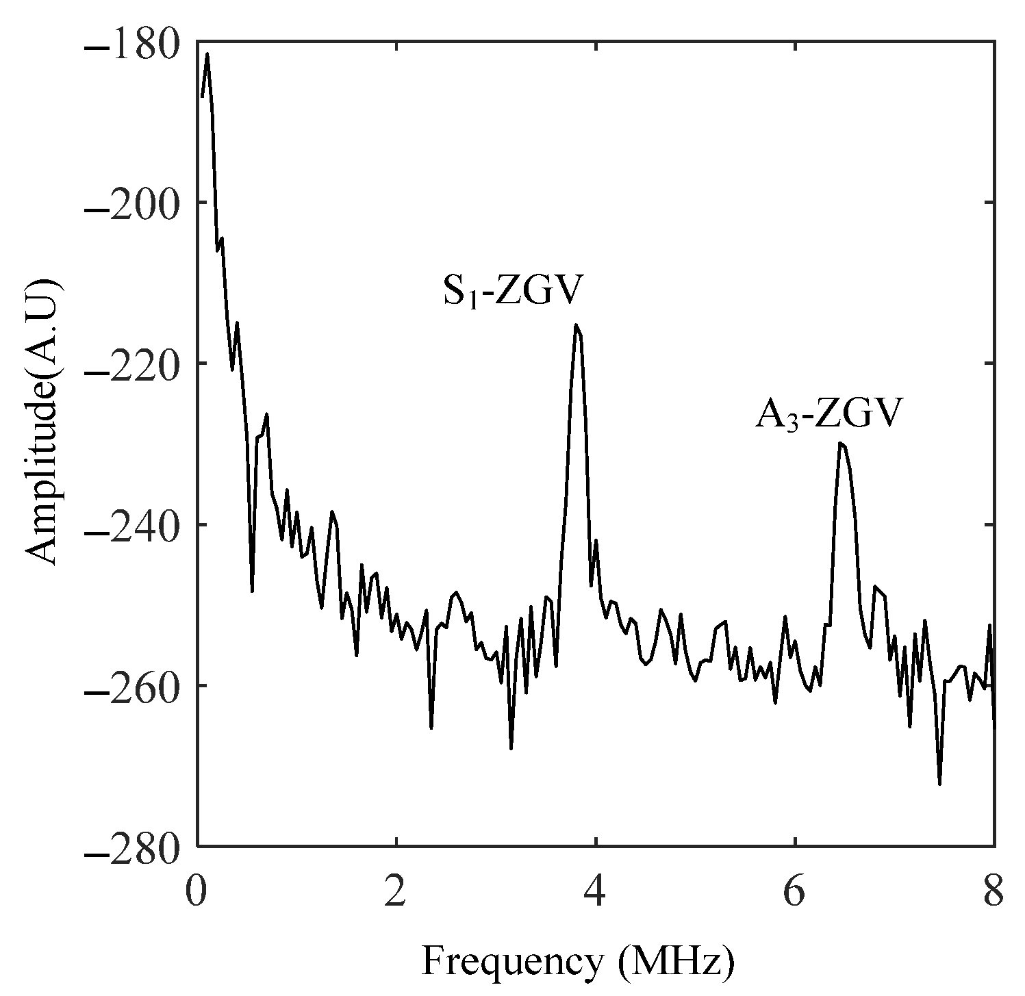
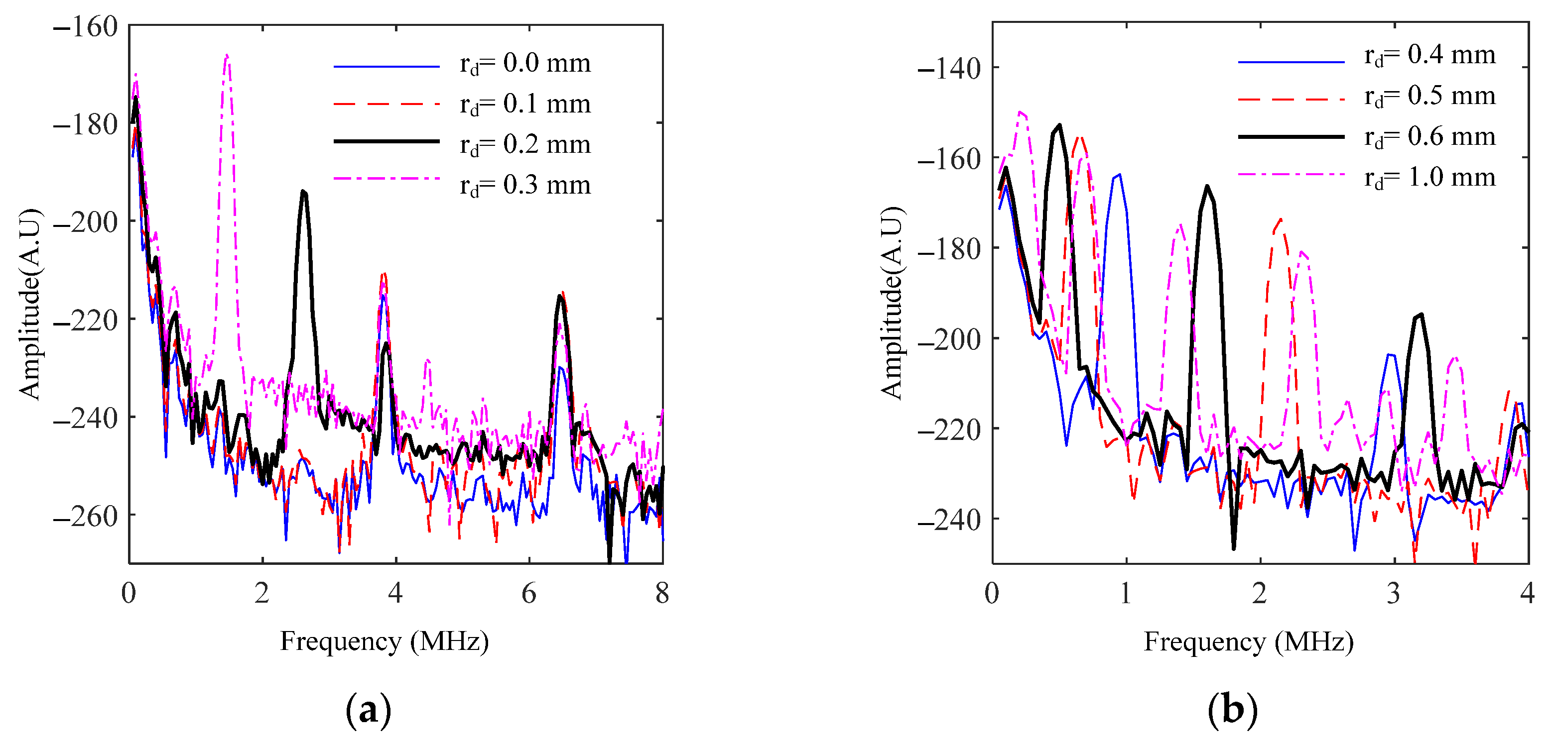
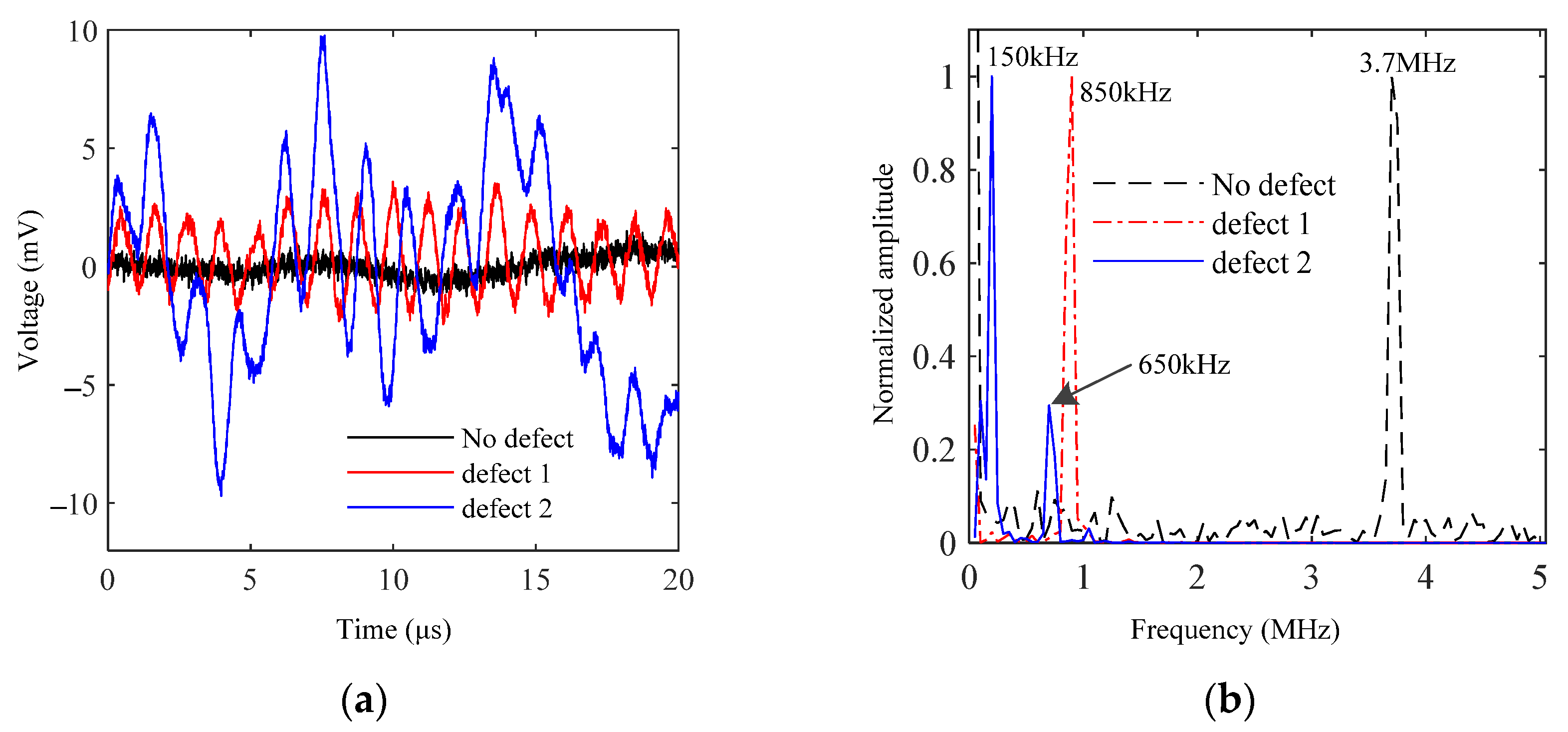
3.1. Analysis of Waveform and Frequency

The delamination defects with different sizes were simulated and analyzed. A Fourier transform of the out-of-plane displacement curve extracted at the center of the thermos-elastic region was carried out to explore the influence of delamination defects on resonance mode. The discrete wavelet transform (DWT, coif2, levels = 11, universal, soft threshold) was used to reduce the low-frequency trend caused by thermal expansion in the waveform, as shown in Figure 4. It is obvious that with the increase in the delamination radius, the out-of-plane displacement increases gradually, and exhibits a significant periodic resonance phenomenon.
Figure 5 shows the frequency spectrum of the waveform in the defect-free model. It is obvious that there are two zero-group velocity (ZGV) resonance modes of the Lamb wave [40,41]; the ZGV resonance frequencies of S1 mode and A3 mode are 3.74 MHz and 6.35 MHz, respectively. Figure 6 shows the influence of the delamination size on the frequency spectrum. It can be seen that the delamination size has a significant effect on the resonance frequency. The existence of delamination defects in the stainless/carbon steel-clad plate leads to the reduction of local stiffness and the change in its local resonance frequency, which can be regarded as the characteristic frequency of delamination defects. When the pulse laser excites the ultrasonic energy at the delamination defect, the ultrasonic energy is confined at the delamination defect, which makes the vibration amplitude near the delamination defect significantly enhanced. With the increase in the delamination radius, the number of resonant modes increases, and the resonant frequency of each mode decreases. Among all resonance modes, the lowest mode has the largest energy.

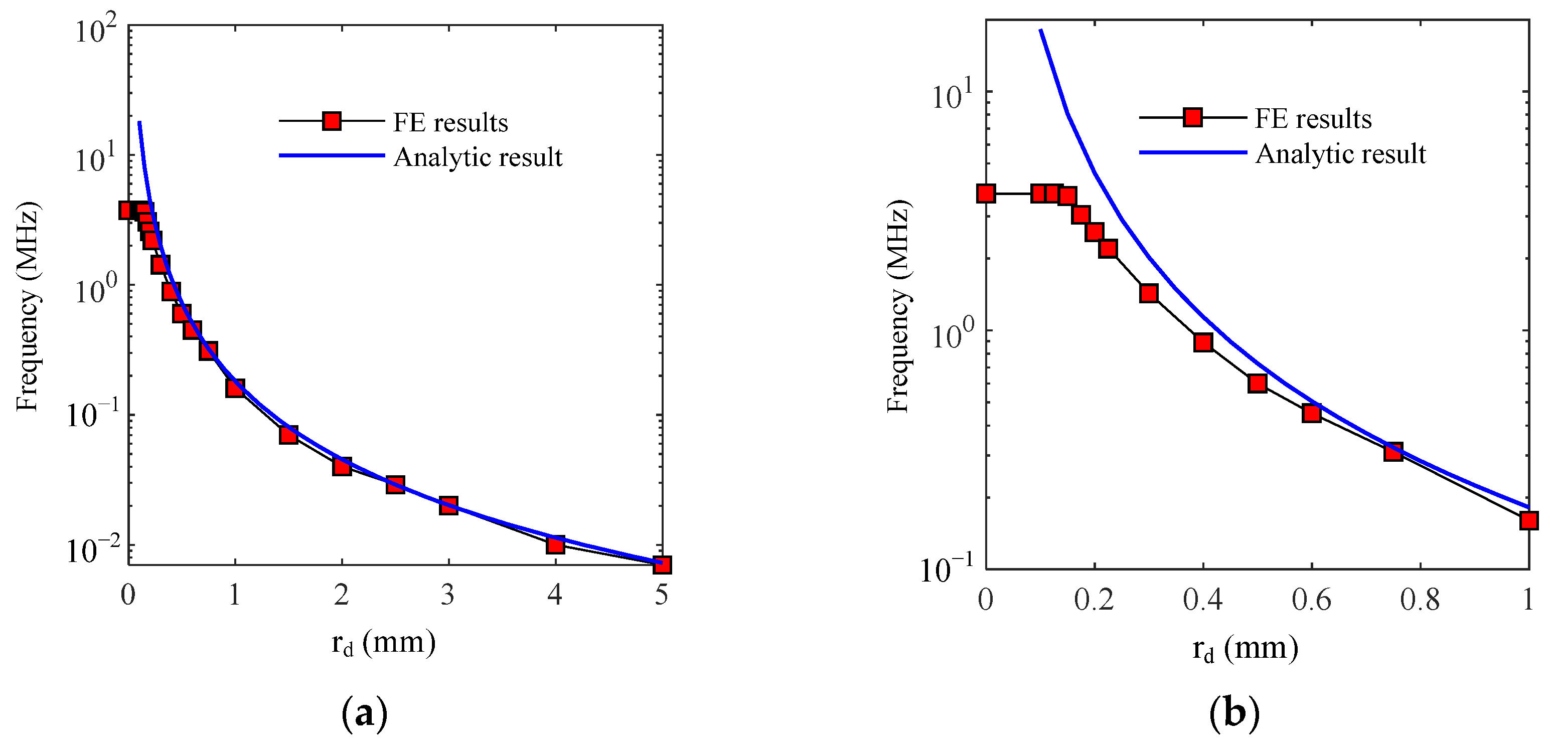
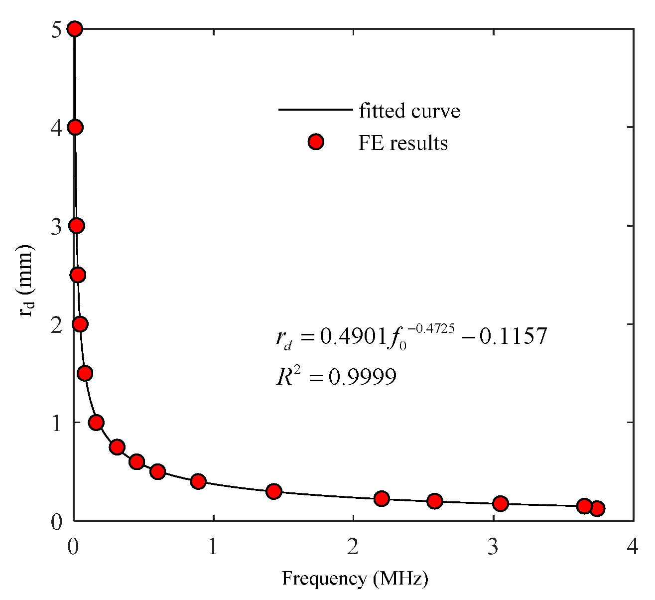
3.2. Quantitative Evaluation of Delamination Sizes

The definition of FRF is the first resonance frequency (that is, the minimum resonance frequency) in the signal. The FRF has the largest energy and the strongest anti-interference ability. Therefore, the FRF is selected as the characteristic parameter for detecting delamination defects. The FRF of the simulation waveform is extracted, and the relationship between the FRF and the delamination radius is shown by the red dotted line in Figure 7. It is clear that when the delamination radius is less than 0.15 mm, the FRF is the resonance frequency of S1-mode ZGV resonance in the defect-free model, and delamination defects have almost no effect on the FRF, indicating that the FRF is insensitive to delamination defects with a radius of less than 0.15 mm. When the delamination radius is greater than 0.15 mm, the FRF decreases rapidly with the increase in the delamination radius. When the delamination radius is larger than 1 mm, the decreasing trend of the FRF becomes slower.
For a well-developed (detached) circular delamination defect, it can be simplified as a flexural resonance of a plate with thickness h and fixed boundary support. The simplified expression of its FRF f0 can be approximated as [32,33]
f 0 1.6 h r d 2 E 12 ρ ( 1 υ 2 )
where E is Young’s modulus, υ is Poisson’s ratio and ρ is the density of the material.
According to Equation (6), the FRFs f0 corresponding to different rd are calculated, and Figure 7 shows the results (solid blue line). Comparing the FE results with the analytical results, it is evident that with the decrease in rd, the error between the two results gradually increases, which indicates that Equation (6) is only applicable when h is much smaller than rd [33]. The analytical formula, expressed in Equation (6), can only provide a very rough estimate of local resonance frequency, while the FE method can provide a more accurate prediction of local resonance frequency. The FE results in Figure 7 are fitted to obtain the estimation formula for the radius of the delamination defects. The fitting curve is shown in Figure 8. The fitting formula is Equation (7), and the R-square is 0.9999. The quantitative method of delamination defects is proposed based on the simulation results of circular delamination defects, so this method is only suitable for the quantitative evaluation of delamination defects that are approximately circular, and not suitable for delamination defects with irregular shapes.
r d = 0.4901 f 0 0.4725 0.1157
where f0 is the first resonance frequency and the value range of f0 is 0.007 MHz ≤ f0 ≤ 3.70 MHz.

3.3. Experimental Signal Analysis
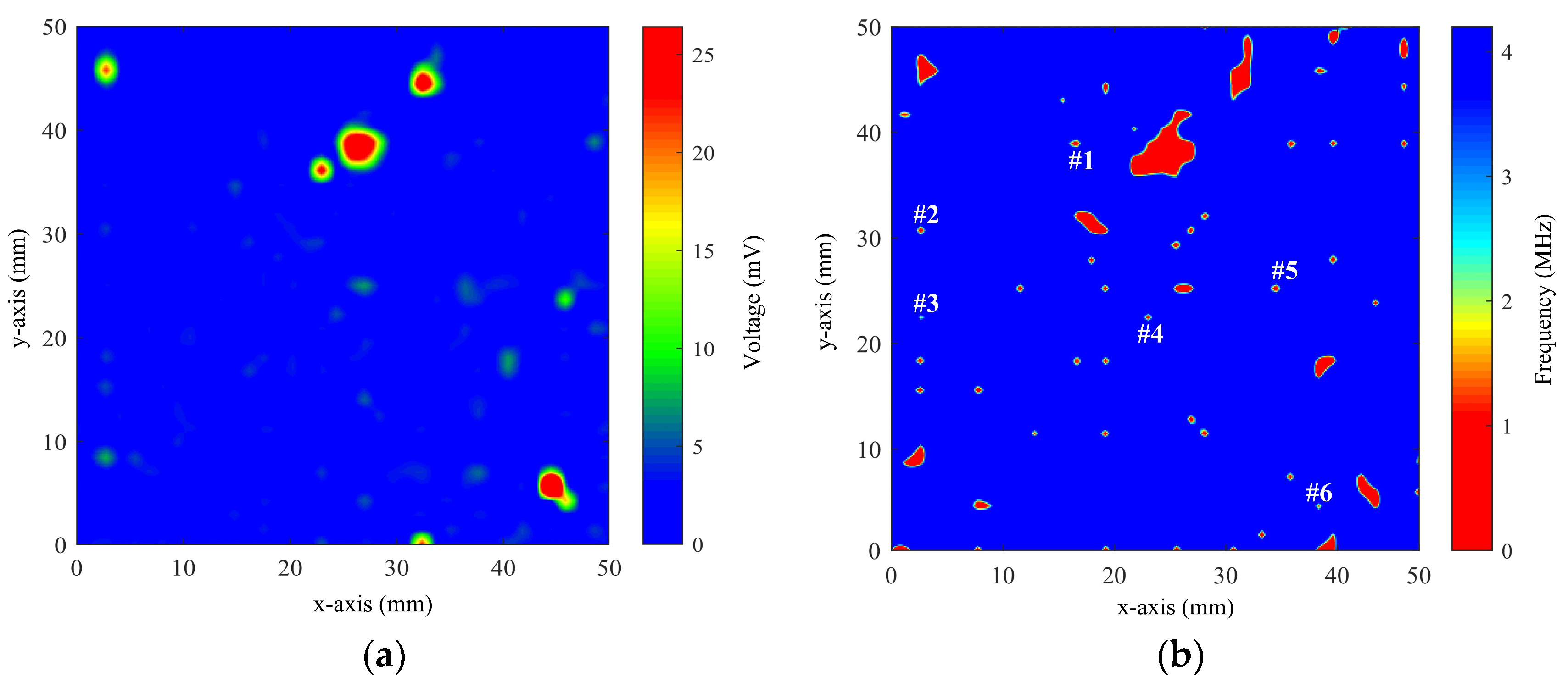
The stainless/carbon steel sample was tested using laser ultrasound. Figure 9a shows the experimental signals collected at three different positions of the specimen; the black curve represents the data collected at the well-compounded area and the other two curves are the data collected at the area with interface delamination. The amplitudes of the experimental signals in the defect region are evidently greater than those in the normal region, and they also have a clear periodic resonance. The frequency spectra of experimental signals in Figure 9a are shown in Figure 9b. Figure 9b shows that the ZGV resonance frequency of S1 mode is 3.7 MHz from the signal without defects, which is consistent with the simulation results in Figure 5. The first resonance frequencies of the signals collected in the two delamination areas are 150 kHz and 850 kHz. According to Equation (7), the size of delamination defects can be estimated approximately. However, the shape of the real delamination defect is complex and cannot be a perfect circle. Therefore, it is difficult to accurately calculate the size of the delamination defect according to the local resonance frequency of the defect.

3.4. C-Scan Results

A C-scan was performed on one side of the specimen. The detection point coincided with the excitation point to ensure that the signal in the central region of the excitation point was collected. The spot diameter of the pulse laser was 1 mm, and the ultrasonic wave was excited with a thermos-elastic mechanism. The spot diameter was about 200 μm and the scanning step was 0.5 mm. The pulse-repetition frequency was 20 Hz. Signal denoising is a key technical problem to be solved in laser ultrasonic testing. The detection power of some laser ultrasonic detection systems is relatively small and cannot be adjusted, and signal processing methods such as wavelet denoising and time-domain average are usually used to improve the signal-to-noise ratio. The power of the detection laser used in this paper is adjustable between 0 and 2 W, and increasing the power of the detection laser can significantly improve the signal-to-noise ratio. In addition, the time-domain average method was adopted to further improve the signal-to-noise ratio. To ensure that the experimental signal has a high signal-to-noise ratio, the detection laser power was set to 1 W, and the time-domain average times were set to 32. The sandpaper was used to polish the surface of the sample to improve the reflectivity of the detected light, which can also improve the signal-to-noise ratio.
The maximum amplitude and the FRF of the experimental signals were extracted for C-scan images, as shown in Figure 10. Figure 10a shows that several large-area delamination defects can be detected using the amplitude feature, but it is difficult to detect tiny delamination defects. The amplitude feature is easily affected by the cleanliness of the surface of the specimen, adding uncertainty to the reliability of the detection results. As can be seen from Figure 10b, the C-scan image obtained with the FRF not only gives several large-area delamination defects but also gives the contours, relative positions and feature sizes of the delamination defects. In addition, the LU local resonance method has higher spatial resolution and can distinguish many tiny delamination defects that cannot be detected using the amplitude feature.
During the experiment, the amplitude of the signal is influenced by many factors, such as the different light reflectivity of different positions of the sample, the interference of environmental vibration and the scanning plane of the probe not being parallel to the surface of the sample. These factors lead to the poor robustness and repeatability of amplitude characteristics. Especially when detecting tiny delamination defects, the possibility of missed detections is greatly increased. Although the above factors will lead to a change in signal amplitude, the frequency characteristics of the signal are basically unaffected. Therefore, the frequency feature has a better anti-interference ability than the amplitude feature.

3.5. Quantitative Characterization of Delamination Defects

As shown in Figure 10b, six tiny delamination defects which are approximately circular are selected and marked as #1, #2, #3, #4, #5 and #6, respectively. The minimum resonance frequencies of these six defects are extracted to estimate the delamination size. Assuming that the shape of these defects is circular, the minimum resonance frequencies of the six positions are substituted into Equation (7) to obtain the radius values, as shown in Table 2. The estimation results show that sub-millimeter delamination defects can be effectively detected.
Generally, the scanning step size has a great influence on the quantitative analysis of defects. The detection efficiency also depends on the scanning step size. If the scanning step size is large, the efficiency is high, but it is easy to miss tiny defects. If the scanning step size is too small, the spatial resolution is high, but the efficiency is too low. Therefore, the scanning step should be set reasonably according to the actual demand. However, the defect quantification method proposed in this paper is less affected by the scanning step size. The essence of this quantitative characterization method is the unique mapping relationship between the flat-bottomed circular hole structure and its lowest resonant frequency, which is almost unaffected by the scanning step size.

4. Conclusions

In this work, the LU local resonance and its interaction with local delamination in stainless/carbon steel-clad plates have been investigated using numerical simulations and experiments. The LU local resonance method has been demonstrated to be effective and reliable for detecting local tiny delamination defects in stainless/carbon steel-clad plates. Furthermore, the influence of the delamination radius has been investigated in the time domain and the frequency domain given the complicated mechanisms at play when LU waves interact with the delamination. The numerical analysis results show that both the amplitude feature and the FRF of the time-domain signals are effective features in characterizing delamination defects, and the FRF has a greater advantage than the amplitude feature in characterizing tiny delamination defects in stainless/carbon steel-clad plates. The C-scan results show that only several large-area delamination defects lacking contour details can be detected using the amplitude feature. The frequency feature not only gives details such as the contour and feature size of large-area delamination defects but can also detect many tiny delamination defects that cannot be detected using amplitude features. The quantitative results of delamination defect size show that sub-millimeter defects can be effectively detected. With the merits of the local resonance method, the LU technique can be implemented for inspecting multilayer clad plates with tiny delamination defects in practical applications. The method proposed in this paper can be improved. For example, the optimal excitation radius and pulse duration of the pulsed laser can be determined to maximize the amplitude of FRF.

Author Contributions

Conceptualization, J.C. and Q.Z.; Methodology, B.J. and Q.Z.; Validation, J.C.; Investigation, B.J.; Resources, J.C. and Q.Z.; Data Curation, B.J.; Writing—Original Draft, B.J.; Visualization, B.J.; Funding Acquisition, B.J., J.C. and Q.Z. All authors have read and agreed to the published version of the manuscript.

Funding

This work is supported by the Postdoctoral Research Foundation of the Shunde Innovation School of the University of Science and Technology Beijing (No. 2022BH009), the National Natural Science Foundation of China (No. 51575040) and the Natural Science Foundation of the Beijing Municipality (No. 3182008).

Institutional Review Board Statement

Not applicable.

Informed Consent Statement

Not applicable.

Data Availability Statement

Data is contained within the article.

Conflicts of Interest

The authors declare no conflicts of interest.

References

  1. Tang, M.; Li, J.; Yu, X.; Nie, S. Tensile behavior of stainless steel clad plates with different cladding ratios. J. Constr. Steel Res. 2021, 182, 106641. [Google Scholar] [CrossRef]
  2. Moon, C.; Won, J.Y.; Lee, K.; Lee, J.; Kim, S.-W.; Lee, M.-G. Mechanical behavior and interfacial damage of carbon steel-stainless steel corrosion resisted-alloy (CRA) cladded plate: Hybrid analysis based on experiment and finite element modeling. Mater. Sci. Eng. A 2022, 852, 143697. [Google Scholar] [CrossRef]
  3. Li, H.; Zhang, L.; Zhang, B.; Zhang, Q. Effect of Heat Treatment on the Microstructure and Corrosion Resistance of Stainless/Carbon Steel Bimetal Plate. Adv. Mater. Sci. Eng. 2020, 2020, 1280761. [Google Scholar] [CrossRef]
  4. Li, H.; Zhang, L.; Zhang, B.; Zhang, Q. Microstructure Characterization and Mechanical Properties of Stainless Steel Clad Plate. Materials 2019, 12, 509. [Google Scholar] [CrossRef] [PubMed]
  5. Ji, B.; Zhang, H.; Cao, J.; Zhang, Q. Evaluation of the Thickness of Each Layer of Cu/Al Laminate Using Laser Ultrasonic. Coatings 2023, 13, 645. [Google Scholar] [CrossRef]
  6. Zhang, Q.; Li, S.; Liu, J.; Wang, Y.; Zhang, B.; Zhang, L. Study of a Bimetallic Interfacial Bonding Process Based on Ultrasonic Quantitative Evaluation. Metals 2018, 8, 329. [Google Scholar] [CrossRef]
  7. Yu, C.; Deng, Z.; Liang, S.; Xiao, H.; Zhao, Y. Effect of pure iron interlayer on microstructure and properties of hot-rolled stainless steel clad plate. Mater. Today Commun. 2021, 28, 102497. [Google Scholar] [CrossRef]
  8. Li, C.a.; Qin, G.; Tang, Y.; Zhang, B.; Lin, S.; Geng, P. Microstructures and mechanical properties of stainless steel clad plate joint with diverse filler metals. J. Mater. Res. Technol. 2020, 9, 2522–2534. [Google Scholar] [CrossRef]
  9. Huang, Q.; Yang, X.; Ma, L.; Zhou, C.; Liu, G.; Li, H. Interface-correlated Characteristics of Stainless Steel/Carbon Steel Plate Fabricated by AAWIV and Hot Rolling. J. Iron. Steel Res. Int. 2014, 21, 931–937. [Google Scholar] [CrossRef]
  10. Ji, B.; Zhang, Q.; Cao, J.; Li, H.; Zhang, B. Non-contact detection of delamination in stainless steel/carbon steel composites with laser ultrasonic. Optik 2021, 226, 165893. [Google Scholar] [CrossRef]
  11. Zhang, H.; Li, C.; Dai, W.; Liu, Y.; Tian, S.; Huang, W.; Jia, D.; He, D.; Zhang, Y. Static compression testing CFRP single-lap composited joints using X-ray μCT. Compos. Struct. 2020, 234, 111667. [Google Scholar] [CrossRef]
  12. Dilonardo, E.; Nacucchi, M.; De Pascalis, F.; Zarrelli, M.; Giannini, C. High resolution X-ray computed tomography: A versatile non-destructive tool to characterize CFRP-based aircraft composite elements. Compos. Sci. Technol. 2020, 192, 108093. [Google Scholar] [CrossRef]
  13. Machado, M.A.; Antin, K.-N.; Rosado, L.S.; Vilaça, P.; Santos, T.G. High-speed inspection of delamination defects in unidirectional CFRP by non-contact eddy current testing. Compos. Part B 2021, 224, 109167. [Google Scholar] [CrossRef]
  14. Yi, Q.; Tian, G.Y.; Malekmohammadi, H.; Laureti, S.; Ricci, M.; Gao, S. Inverse reconstruction of fibre orientation in multilayer CFRP using forward FEM and eddy current pulsed thermography. NDT E Int. 2021, 122, 102474. [Google Scholar] [CrossRef]
  15. Ashizawa, T.; Mizutani, Y.; Toyama, N.; Todoroki, A.; Suzuki, Y. Similarity law for two-dimensional propagation behavior of ultrasonic wave in concentrically curved fiber CFRP. Compos. Struct. 2020, 233, 111714. [Google Scholar] [CrossRef]
  16. Cao, H.; Guo, S.; Zhang, S.; Xie, Y.; Feng, W. Ray tracing method for ultrasonic array imaging of CFRP corner part using homogenization method. NDT E Int. 2021, 122, 102493. [Google Scholar] [CrossRef]
  17. Dattoma, V.; Nobile, R.; Panella, F.W.; Saponaro, A. NDT thermographic techniques on CFRP structural components for aeronautical application. Procedia Struct. Integr. 2018, 8, 452–461. [Google Scholar] [CrossRef]
  18. Dattoma, V.; Willem Panella, F.; Pirinu, A.; Saponaro, A. Ultrasonic and thermographic studies for CFRP inspections with real and simulated defects. Mater. Today Proc. 2021, 34, 224–234. [Google Scholar] [CrossRef]
  19. Spytek, J.; Ziaja-Sujdak, A.; Dziedziech, K.; Pieczonka, L.; Pelivanov, I.; Ambrozinski, L. Evaluation of disbonds at various interfaces of adhesively bonded aluminum plates using all-optical excitation and detection of zero-group velocity Lamb waves. NDT E Int. 2020, 112, 102249. [Google Scholar] [CrossRef]
  20. Park, B.; An, Y.-K.; Sohn, H. Visualization of hidden delamination and debonding in composites through noncontact laser ultrasonic scanning. Compos. Sci. Technol. 2014, 100, 10–18. [Google Scholar] [CrossRef]
  21. Watzl, G.; Kerschbaummayr, C.; Schagerl, M.; Mitter, T.; Sonderegger, B.; Grünsteidl, C. In situ laser-ultrasonic monitoring of Poisson’s ratio and bulk sound velocities of steel plates during thermal processes. Acta Mater. 2022, 235, 118097. [Google Scholar] [CrossRef]
  22. Chia, C.C.; Lee, J.-R.; Park, C.-Y.; Jeong, H.-M. Laser ultrasonic anomalous wave propagation imaging method with adjacent wave subtraction: Application to actual damages in composite wing. Opt. Laser Technol. 2012, 44, 428–440. [Google Scholar] [CrossRef]
  23. Sattar, H.; Ran, H.; Hu, Z.; Guan, F.; Imran, M.; Guo, L.; Luo, W.; Ding, H. Simultaneous analysis of long-pulse laser irradiated plasma-facing materials (PFMs) microstructure and hardness by in-situ laser Opto-ultrasonic dual detection (LOUD). Opt. Laser Technol. 2023, 157, 108741. [Google Scholar] [CrossRef]
  24. Zhang, K.; Li, S.; Zhou, Z. Detection of disbonds in multi-layer bonded structures using the laser ultrasonic pulse-echo mode. Ultrasonics 2019, 94, 411–418. [Google Scholar] [CrossRef]
  25. Sun, G.; Zhao, L.; Dong, M.; Lou, X.; Zhu, L. Non-contact characterization of debonding in lead-alloy steel bonding structure with laser ultrasound. Optik 2018, 164, 734–744. [Google Scholar] [CrossRef]
  26. Shin, H.-J.; Choi, Y.; Lee, J.-R. Damage visualization of a cylindrical CFRP lattice-skin structure based on a pulse-echo ultrasonic propagation imager. Measurement 2019, 147, 106837. [Google Scholar] [CrossRef]
  27. Gao, T.; Liu, X.; Zhu, J.; Zhao, B.; Qing, X. Multi-frequency localized wave energy for delamination identification using laser ultrasonic guided wave. Ultrasonics 2021, 116, 106486. [Google Scholar] [CrossRef]
  28. Ji, B.; Cao, J.; Yu, M.; Chen, Z.; Zhang, Q. Application of laser ultrasonic for detecting delamination in Cu/Al composites. Optik 2021, 243, 167426. [Google Scholar] [CrossRef]
  29. Ji, B.; Zhang, Q.; Cao, J.; Zhang, B.; Zhang, L. Delamination detection in bimetallic composite using laser ultrasonic bulk waves. Appl. Sci. 2021, 11, 636. [Google Scholar] [CrossRef]
  30. Jiao, J.; Li, L.; Ma, B.; He, C.; Wu, B. Quantitative detection method of plate structure defects based on ultrasonic local resonance. Chin. J. Sci. Instrum. 2019, 40, 1204. [Google Scholar]
  31. Sarens, B.; Verstraeten, B.; Glorieux, C.; Kalogiannakis, G.; Van Hemelrijck, D. Investigation of contact acoustic nonlinearity in delaminations by shearographic imaging, laser doppler vibrometric scanning and finite difference modeling. IEEE Trans. Ultrason. Ferroelectr. Freq. Control 2010, 57, 1383–1395. [Google Scholar] [CrossRef]
  32. Solodov, I.; Bai, J.; Bekgulyan, S.; Busse, G. A local defect resonance to enhance acoustic wave-defect interaction in ultrasonic nondestructive evaluation. Appl. Phys. Lett. 2011, 99, 211911. [Google Scholar] [CrossRef]
  33. Solodov, I.; Bai, J.; Busse, G. Resonant ultrasound spectroscopy of defects: Case study of flat-bottomed holes. J. Appl. Phys. 2013, 113, 223512. [Google Scholar] [CrossRef]
  34. Solodov, I.; Derusova, D.; Rahammer, M. Thermosonic Chladni figures for defect-selective imaging. Ultrasonics 2015, 60, 1–5. [Google Scholar] [CrossRef] [PubMed]
  35. Solodov, I.; Rahammer, M.; Gulnizkij, N.; Kreutzbruck, M. Noncontact Sonic NDE and Defect Imaging Via Local Defect Resonance. J. Nondestr. Eval. 2016, 35, 48. [Google Scholar] [CrossRef]
  36. Hettler, J.; Tabatabaeipour, M.; Delrue, S.; Van Den Abeele, K. Detection and Characterization of Local Defect Resonances Arising from Delaminations and Flat Bottom Holes. J. Nondestr. Eval. 2016, 36, 2. [Google Scholar] [CrossRef]
  37. Rus, J.; Grosse, C.U. Local Ultrasonic Resonance Spectroscopy: A Demonstration on Plate Inspection. J. Nondestr. Eval. 2020, 39, 31. [Google Scholar] [CrossRef]
  38. Rus, J.; Grosse, C.U. Thickness measurement via local ultrasonic resonance spectroscopy. Ultrasonics 2021, 109, 106261. [Google Scholar] [CrossRef]
  39. Segers, J.; Kersemans, M.; Hedayatrasa, S.; Calderon, J.; Van Paepegem, W. Towards in-plane local defect resonance for non-destructive testing of polymers and composites. NDT E Int. 2018, 98, 130–133. [Google Scholar] [CrossRef]
  40. Glushkov, E.V.; Glushkova, N.V. Multiple zero-group velocity resonances in elastic layered structures. J. Sound Vib. 2021, 500, 116023. [Google Scholar] [CrossRef]
  41. Grünsteidl, C.; Murray, T.W.; Berer, T.; Veres, I.A. Inverse characterization of plates using zero group velocity Lamb modes. Ultrasonics 2016, 65, 1–4. [Google Scholar] [CrossRef] [PubMed]
Figure 1. The schematic diagram of the stainless/carbon steel-clad plate. (a) Defect-free model. (b) Model with delamination defect.
Coatings 14 00474 g001
Figure 2. Specimen of stainless/carbon steel-clad plate.
Coatings 14 00474 g002
Figure 3. A diagram of the LU system.
Coatings 14 00474 g003
Figure 4. Out-of-plane displacement corresponding to different rd. (a) 0 mm, 0.1 mm, 0.2 mm and 0.3 mm. (b) 0.4 mm, 0.5 mm, 0.6 mm and 1 mm.
Coatings 14 00474 g004
Figure 5. Frequency spectra of displacement responses measured at the defect-free model.
Coatings 14 00474 g005
Figure 6. Frequency spectra of displacement responses corresponding to different rd. (a) 0 mm, 0.1 mm, 0.2 mm and 0.3 mm. (b) 0.4 mm, 0.5 mm, 0.6 mm and 1 mm.
Coatings 14 00474 g006
Figure 7. The relationship between FRF and rd. (a) The value range of rd is 0 to 5 mm. (b) Partial enlargement.
Coatings 14 00474 g007
Figure 8. Fitting curve of the minimum resonance frequency and rd.
Coatings 14 00474 g008
Figure 9. The experimental signals and their spectra. (a) Time-domain signals of three regions. (b) Frequency spectra.
Coatings 14 00474 g009
Figure 10. C-scan images of the specimen. (a) Imaging result based on the amplitude of the signals. (b) Imaging results based on the FRF of the signals.
Coatings 14 00474 g010
Table 1. The thermos-physical parameters used in numerical simulation.
Material PropertiesQ235304
Thermal conductivity (W × m−1 × K−1)80.316.3
Density (g × cm³)7.867.93
Poisson’s ratio0.30.3
Thermal expansion coefficient (10−6 K−1)10.617.2
Young’s modulus (GPa)210200
Heat capacity (J × kg−1 × K−1)465500
Table 2. The estimated value of the defect radius.
Parameter#1#2#3#4#5#6
Minimum resonance frequency (MHz)0.290.851.501.000.651.10
Defect radius rd (mm)0.76390.41350.28900.37440.48500.3528
Disclaimer/Publisher’s Note: The statements, opinions and data contained in all publications are solely those of the individual author(s) and contributor(s) and not of MDPI and/or the editor(s). MDPI and/or the editor(s) disclaim responsibility for any injury to people or property resulting from any ideas, methods, instructions or products referred to in the content.

