
Self-Healing Phenomenon at the Cut Edge of Zn-Al-Mg Alloy Coated Steel in Chloride Environments
 ,
,
Abstract
:1. Introduction
2. Materials and Methods
2.1. Specimens Preparation
2.2. Corrosion Tests
2.3. Materials Characterization
3. Results and Discussion
4. Conclusions
Author Contributions
Funding
Institutional Review Board Statement
Informed Consent Statement
Data Availability Statement
Conflicts of Interest
References
- Shibli, S.; Meena, B.N.; Remya, R. A review on recent approaches in the field of hot dip zinc galvanizing process. Surf. Coat. Technol. 2015, 262, 210–215. [Google Scholar] [CrossRef]
- Dutta, M.; Halder, A.K.; Singh, S.B. Morphology and properties of hot dip Zn–Mg and Zn–Mg–Al alloy coatings on steel sheet. Surf. Coat. Technol. 2010, 205, 2578–2584. [Google Scholar] [CrossRef]
- Yeomans, S.R. Galvanized Steel Reinforcement: Recent Developments and New Opportunities. In Proceedings of the 5th International Federation for Structural Concrete, Melbourne, VIC, Australia, 7–11 October 2018; pp. 7–11. [Google Scholar]
- Diler, E.; Rouvellou, B.; Rioual, S.; Lescop, B.; Vien, G.N.; Thierry, D. Characterization of corrosion products of Zn and Zn–Mg–Al coated steel in a marine atmosphere. Corros. Sci. 2014, 87, 111–117. [Google Scholar] [CrossRef]
- Stoulil, J.; Prosek, T.; Nazarov, A.; Oswald, J.; Kriz, P.; Thierry, D. Electrochemical properties of corrosion products formed on Zn-Mg, Zn-Al and Zn-Al-Mg coatings in model atmospheric conditions. Mater. Corros. 2015, 66, 777–782. [Google Scholar] [CrossRef]
- Rai, P.K.; Rout, D.; Kumar, D.S.; Sharma, S.; Balachandran, G. Corrosion behaviour of hot-dip Zn-Al-Mg coatings with different Al content. Anti-Corros. Methods Mater. 2022, 69, 29–37. [Google Scholar] [CrossRef]
- Ye, C.; Jia, L.; Xu, G.; Wang, F.; Wang, X.; Zhang, H. Microstructure and initial corrosion behavior of double-layer Zn-Al-Mg coatings produced by PVD. Surf. Coat. Technol. 2019, 366, 214–226. [Google Scholar] [CrossRef]
- Bakhsheshi-Rad, H.R.; Hamzah, E.; Low, H.T.; Kasiri-Asgarani, M.; Farahany, S.; Akbari, E.; Cho, M.H. Fabrication of biodegradable Zn-Al-Mg alloy: Mechanical properties, corrosion behavior, cytotoxicity and antibacterial activities. Mater. Sci. Eng. C 2017, 73, 215–219. [Google Scholar] [CrossRef] [PubMed]
- Yao, C.; Lv, H.; Zhu, T.; Zheng, W.; Yuan, X.; Gao, W. Effect of Mg content on microstructure and corrosion behavior of hot dipped Zn–Al–Mg coatings. J. Alloys Compd. 2016, 670, 239–248. [Google Scholar] [CrossRef]
- Duchoslav, J.; Steinberger, R.; Arndt, M.; Keppert, T.; Luckeneder, G.; Stellnberger, K.H.; Hagler, J.; Angeli, G.; Riener, C.K.; Stifter, D. Evolution of the surface chemistry of hot dip galvanized Zn–Mg–Al and Zn coatings on steel during short term exposure to sodium chloride containing environments. Corros. Sci. 2015, 91, 311–320. [Google Scholar] [CrossRef]
- Sanni, O.; Iwarere, S.A.; Daramola, M.O. Introduction: Corrosion basics and corrosion testing. In Electrochemical and Analytical Techniques for Sustainable Corrosion Monitoring; Elsevier: Amsterdam, The Netherlands, 2023; pp. 1–23. [Google Scholar]
- Chen, H.; Lv, Z.; Lu, L.; Huang, Y.; Li, X. Correlation of micro-galvanic corrosion behavior with corrosion rate in the initial corrosion process of dual phase steel. J. Mater. Res. Technol. 2021, 15, 3310–3320. [Google Scholar] [CrossRef]
- Sheikholeslami, S.; Williams, G.; McMurray, H.N.; Gommans, L.; Morrison, S.; Ngo, S.; Williams, D.E.; Gao, W. Cut-edge corrosion behavior assessment of newly developed environmental-friendly coating systems using the Scanning Vibrating Electrode Technique (SVET). Corros. Sci. 2021, 192, 109813. [Google Scholar] [CrossRef]
- Yıldız, R.; Dehri, I. Investigation of the cut-edge corrosion of organically-coated galvanized steel after accelerated atmospheric corrosion test. Arab. J. Chem. 2015, 8, 821–827. [Google Scholar] [CrossRef]
- Marques, A.G.; Izquierdo, J.; Souto, R.M.; Simões, A.M. SECM imaging of the cut edge corrosion of galvanized steel as a function of pH. Electrochim. Acta 2015, 153, 238–245. [Google Scholar] [CrossRef]
- Turnbull, A.; Mingard, K.; Lord, J.D.; Roebuck, B.; Tice, D.R.; Mottershead, K.J.; Fairweather, N.D.; Bradbury, A.K. Sensitivity of stress corrosion cracking of stainless steel to surface machining and grinding procedure. Corros. Sci. 2011, 53, 3398–3415. [Google Scholar] [CrossRef]
- Worsley, D.A.; Williams, D.; Ling, J. Mechanistic changes in cut-edge corrosion induced by variation of organic coating porosity. Corros. Sci. 2001, 43, 2335–2348. [Google Scholar] [CrossRef]
- Son, I.R.; Kim, T.C.; Ju, G.I.; Kim, M.S.; Kim, J.S. Development of PosMAC® Steel and Its Application Properties. Korean J. Met. Mater. 2021, 59, 613–623. [Google Scholar] [CrossRef]
- Kim, T.C.; Kim, S.H.; Kim, S.Y.; Oh, M.S.; Yu, B.H.; Kim, J.S. Hot dip Zn-Al-Mg Alloy Plated Steel Sheet Having Excellent Corrosion Resistance and Method for Manufacturing. K.R. Patent 101,568,509, 20 November 2015. [Google Scholar]
- ASTM B117-03; Standard Practice for Operating Salt Spray Apparatus. ASTM: West Conshohocken, PA, USA, 2003.
- Krieg, R.; Rohwerder, M.; Evers, S.; Schuhmacher, B.; Schauer-Pass, J. Cathodic self-healing at cut-edges: The effect of Zn2 and Mg2 ions. Corros. Sci. 2012, 65, 119–127. [Google Scholar] [CrossRef]
- Kim, B.S.; Kim, Y.W.; Lee, K.H.; Yang, J.H. Corrosion image analysis on galvanized steel by using superpixel DBSCAN clustering algorithm. Korean Inst. Surf. Eng. 2022, 55, 164–172. [Google Scholar]
- Yao, C.; Tay, S.L.; Zhu, T.; Shang, H.; Gao, W. Effects of Mg content on microstructure and electrochemical properties of Zn–Al–Mg alloys. J. Alloys Compd. 2015, 645, 131–136. [Google Scholar] [CrossRef]
- Hodoroaba, V.; Kim, K.J.; Unger, W.E. Energy dispersive electron probe microanalysis (ED-EPMA) of elemental composition and thickness of Fe-Ni alloy films. Surf. Interface Anal. 2012, 44, 1459–1461. [Google Scholar] [CrossRef]
- Ishikawa, T.; Matsumoto, K.; Kandori, K.; Nakayama, T. Synthesis of layered zinc hydroxide chlorides in the presence of Al (III). J. Solid State Chem. 2006, 179, 1110–1118. [Google Scholar] [CrossRef]
- Azevedo, M.S.; Allély, C.; Ogle, K.; Volovitch, P. Corrosion mechanisms of Zn (Mg, Al) coated steel: 2. The effect of Mg and Al alloying on the formation and properties of corrosion products in different electrolytes. Corros. Sci. 2015, 90, 482–490. [Google Scholar] [CrossRef]
- Wint, N.; Malla, A.D.; Cooze, N.; Savill, T.; Mehraban, S.; Dunlop, T.; Sullivan, J.H.; Penney, D.; Williams, G.; McMurray, H.N. The ability of Mg2Ge crystals to behave as ‘smart release’inhibitors of the aqueous corrosion of Zn-Al-Mg alloys. Corros. Sci. 2021, 179, 109091. [Google Scholar] [CrossRef]
- Hausbrand, R.; Stratmann, M.; Rohwerder, M. Corrosion of zinc–magnesium coatings: Mechanism of paint delamination. Corros. Sci. 2009, 51, 2107–2114. [Google Scholar] [CrossRef]
- Byun, J.M.; You, J.M.; Kim, D.K.; Kim, T.Y.; Jeong, W.S.; Kim, Y.D. Corrosion Behavior of Mg2Zn11 and MgZn2 Single Phases. Korean J. Met. Mater. 2013, 51, 413–419. [Google Scholar] [CrossRef]
- Voith, M.; Mardare, A.I.; Hassel, A.W. Synthesis and characterization of Al–M g–Z n thin film alloys co-deposited from vapour phase. Phys. Status Solidi A 2013, 210, 1000–1005. [Google Scholar] [CrossRef]
- Volovitch, P.; Allely, C.; Ogle, K. Understanding corrosion via corrosion product characterization: I. Case Study of the Role of Mg Alloying in Zn–Mg coating on steel. Corros. Sci. 2009, 51, 1251–1262. [Google Scholar]
- Conway, B.E.; Kannangara, D. Zinc oxidation and redeposition processes in aqueous alkali and carbonate solutions: II. Distinctinction between Dissolution and Oxide Film Formation Processes. J. Electrochem. Soc. 1987, 134, 906. [Google Scholar]
- Ishikawa, T.; Matsumoto, K.; Yasukawa, A.; Kandori, K.; Nakayama, T.; Tsubota, T. Influence of metal ions on the formation of artificial zinc rusts. Corros. Sci. 2004, 46, 329–342. [Google Scholar] [CrossRef]
- Anjum, M.J.; Zhao, J.; Ali, H.; Tabish, M.; Murtaza, H.; Yasin, G.; Malik, M.U.; Khan, W.Q. A review on self-healing coatings applied to Mg alloys and their electrochemical evaluation techniques. Int. J. Electrochem. Sci. 2020, 15, 3040–3053. [Google Scholar] [CrossRef]
- Vu, A.Q.; Vuillemin, B.; Oltra, R.; Allély, C. Cut-edge corrosion of a Zn–55Al-coated steel: A comparison between sulphate and chloride solutions. Corros. Sci. 2011, 53, 3016–3025. [Google Scholar] [CrossRef]


| Specimens | Zn (wt.%) | Al (wt.%) | Mg (wt.%) |
|---|---|---|---|
| ZA | 98~100 | 0~2 | - |
| ZMA2 | 93~97 | 1~3 | 2~4 |
| ZMA4 | 81~86 | 10~13 | 4~6 |
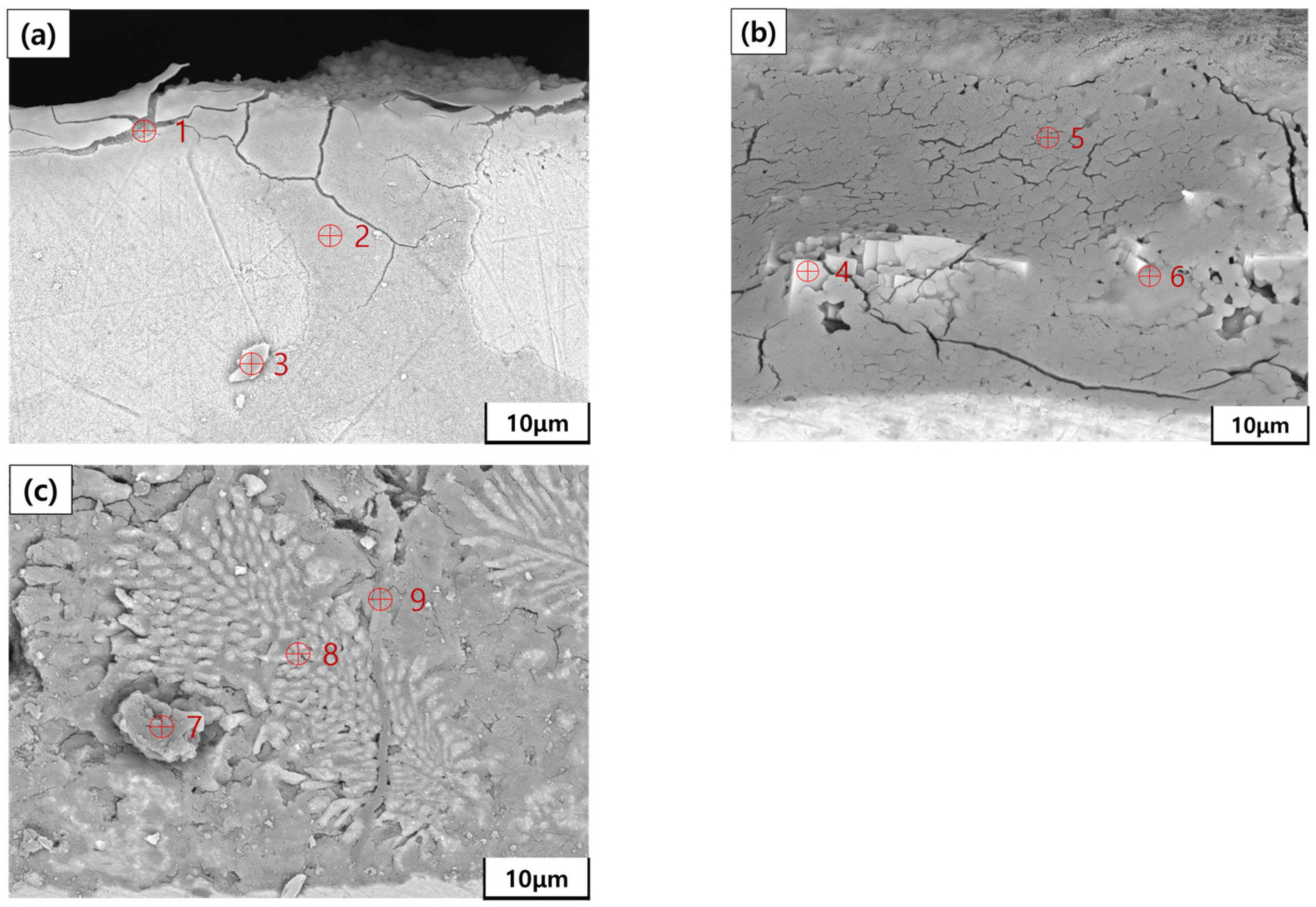
| Point | Zn (wt.%) | Al (wt.%) | Mg (wt.%) | Fe (wt.%) | O (wt.%) |
|---|---|---|---|---|---|
| 1 | 3.82 | - | - | 78.46 | 17.72 |
| 2 | - | - | - | 96.26 | 3.74 |
| 3 | - | - | - | 91.38 | 8.62 |
| Point | Zn (wt.%) | Al (wt.%) | Mg (wt.%) | Fe (wt.%) | O (wt.%) |
|---|---|---|---|---|---|
| 4 | 44.90 | - | - | 7.95 | 47.15 |
| 5 | - | - | - | 23.93 | 76.07 |
| 6 | 14.72 | 12.67 | - | 22.31 | 50.30 |
| Point | Zn (wt.%) | Al (wt.%) | Mg (wt.%) | Fe (wt.%) | O (wt.%) |
|---|---|---|---|---|---|
| 7 | 35.19 | 9.70 | - | 4.16 | 50.95 |
| 8 | 41.90 | 46.95 | - | 2.66 | 8.49 |
| 9 | 57.86 | 0.25 | 0.17 | 2.53 | 39.19 |
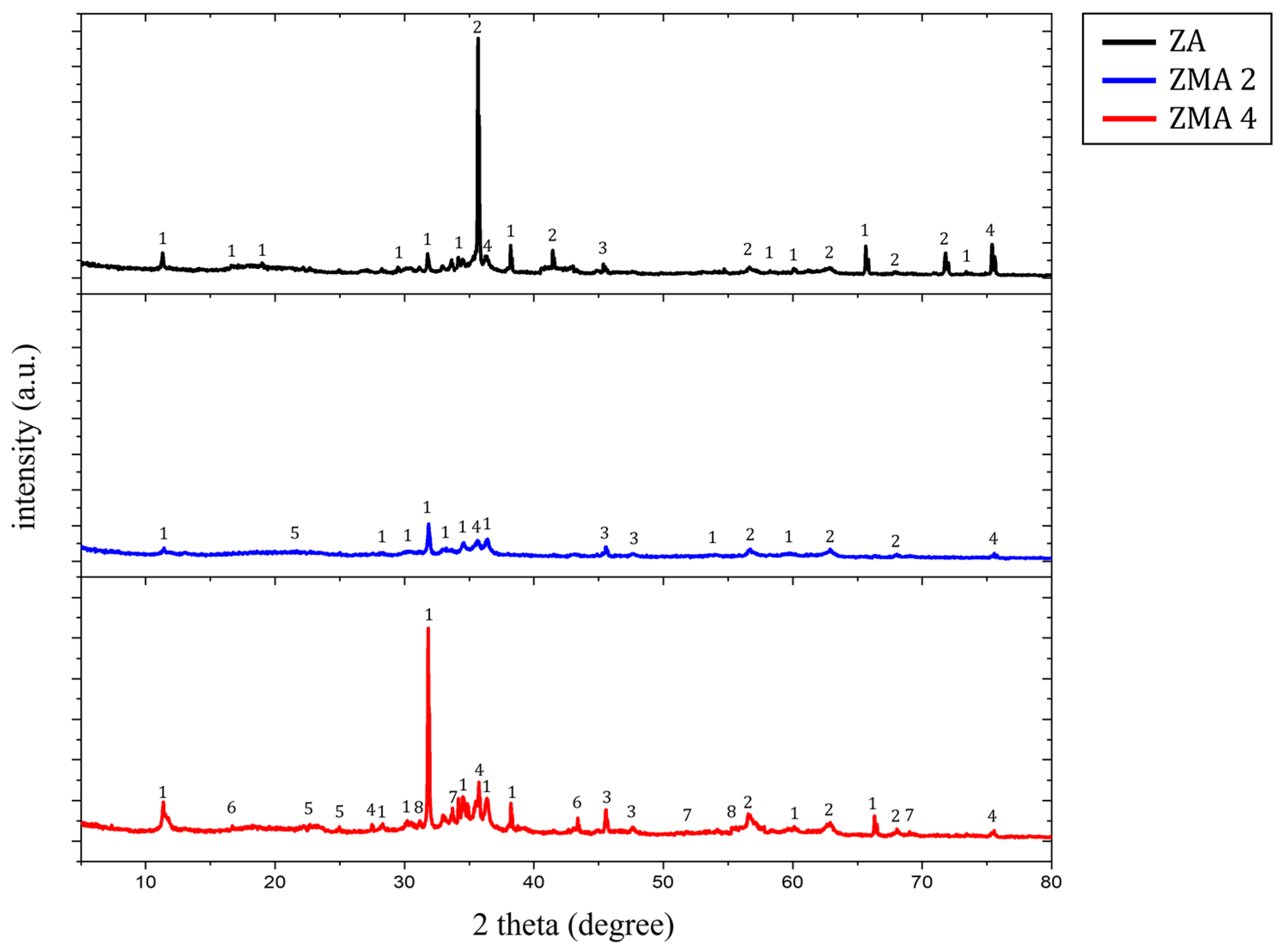
| Label | Name | Chemical Formula | Label | Name | Chemical Formula |
|---|---|---|---|---|---|
| 1 | Simonkolleite | 5 | LDH | [M(II)1−x·M(III)x(OH)2]x+[An−]x/n, M(II) = Zn2+, Mg2+, M(III) = Al3+ | |
| 2 | Zincite, Zinc Oxide | 6 | Magnesium Hydroxide | Mg(OH)2 | |
| 3 | Zinc Hydroxide | 7 | Magnesium Hydroxide Chloride | Mg2(OH)3Cl | |
| 4 | Aluminum Oxide | 8 | Zinc Chlorate Hydrate | Zn(ClO2)2(H2O)2 |
Disclaimer/Publisher’s Note: The statements, opinions and data contained in all publications are solely those of the individual author(s) and contributor(s) and not of MDPI and/or the editor(s). MDPI and/or the editor(s) disclaim responsibility for any injury to people or property resulting from any ideas, methods, instructions or products referred to in the content. |
© 2024 by the authors. Licensee MDPI, Basel, Switzerland. This article is an open access article distributed under the terms and conditions of the Creative Commons Attribution (CC BY) license (https://creativecommons.org/licenses/by/4.0/).
Share and Cite
Kim, S.-H.; Jin, S.-Y.; Yang, J.-H.; Yang, J.-H.; Lee, M.-H.; Yun, Y.-S. Self-Healing Phenomenon at the Cut Edge of Zn-Al-Mg Alloy Coated Steel in Chloride Environments. Coatings 2024, 14, 485. https://doi.org/10.3390/coatings14040485
Kim S-H, Jin S-Y, Yang J-H, Yang J-H, Lee M-H, Yun Y-S. Self-Healing Phenomenon at the Cut Edge of Zn-Al-Mg Alloy Coated Steel in Chloride Environments. Coatings. 2024; 14(4):485. https://doi.org/10.3390/coatings14040485
Chicago/Turabian StyleKim, Sang-Hee, Seo-Yun Jin, Ji-Hoon Yang, Jeong-Hyeon Yang, Myeong-Hoon Lee, and Yong-Sup Yun. 2024. "Self-Healing Phenomenon at the Cut Edge of Zn-Al-Mg Alloy Coated Steel in Chloride Environments" Coatings 14, no. 4: 485. https://doi.org/10.3390/coatings14040485