Article

Study on Microstructure, Mechanical Properties, Tribological Properties and Service Performance of CrAlN and CrAlBN Coatings Deposited on Powder Metallurgy High-Speed Steel (PM-HSS) and Shaper Cutter by Arc Ion Plating Technique

1
School of Mechanical Engineering and Automation, Northeastern University, Shenyang 110004, China
2
NeuMat (Tai’an) Surface Technology Limited, Taian 271024, China
*
Author to whom correspondence should be addressed.
Coatings 2024, 14(4), 486; https://doi.org/10.3390/coatings14040486
Submission received: 1 March 2024 / Revised: 2 April 2024 / Accepted: 9 April 2024 / Published: 15 April 2024
(This article belongs to the Section Corrosion, Wear and Erosion)

Abstract

:
CrAlN and CrAlBN coatings were prepared on the surface of high-speed steel and shaper cutter by physical vapor deposition (PVD) technique using arc ion source. In the process of coating preparation, the adhesive layers were deposited by low bias voltage (−40 V) and the working layers are deposited by high bias voltage (−130 V). The effects of the addition of B element on the microstructure, hardness, elastic modulus and wear resistance of CrAlBN coating were studied. The results show that B element and its compounds exist in amorphous form in the coating, resulting in lattice distortion of the coating, increase of coating hardness to 37.1 GPa, and decrease of elastic modulus to 406.2 GPa. The addition of B element increases the uniformity of the columnar structure distribution and decreases the width of the columnar structure and grain size. The resistance to elastic deformation and plastic deformation of CrAlBN coating is improved, the wear resistance is improved. The performance of CrAlN and CrAlBN coatings on shaper cutter was studied. It was found that the main failure mode of shaper cutters is boundary wear and the wear mechanism of coatings had changed obviously. CrAlBN coating is mainly due to fatigue induced failure, accompanied by some diffusion wear. The addition of B element makes the CrAlBN coating have excellent resistance to oxidative wear, abrasive wear and diffusion wear during cutting. The results show that the addition of B element can improve the microstructure and mechanical properties of CrAlN coating, and the preparation of CrAlBN coating on the surface of the shaper cutter can significantly improve the service life of the coated shaper cutter, which has significance for the development of the shaper cutter industry.

1. Introduction

Due to the advantages of large transmission ratio and strong carrying capacity, planetary gear is widely used in aerospace, automobiles, wind turbines, heavy trucks and other heavy industry fields [1,2]. The shaper cutter is used to process internal gears, and the pinion shaper cutter can also be used to manufacture involute cylindrical gears [3]. Because the accuracy and service life of the tool directly affect the manufacturing cost and productivity of the gear production, with the gear production industry’s requirements for high productivity and low manufacturing costs are getting higher and higher, improving the manufacturing accuracy and service life of the shaper cutter has attracted widespread attention. In the process of design, manufacture and use of shaper cutters, a series of methods such as tooth profile correction [4,5,6,7,8,9,10], tool changing materials [11,12,13] and online monitoring [14] are often used to improve the life of the tool and the accuracy of the gear. Because the shaper cutter works in an intermittent cutting mode, it will produce certain wear on the cutting edge under the action of high load during the cutting process, thus affecting the production efficiency and the surface quality of the gear [15]. In addition, there will be a certain amount of heat generated in the cutting process [16], so the high temperature stability of the tool is very important.
As a kind of tool steel, high-speed steel (HSS) has been widely used in gear tool industry. Worn cutting edges affect the quality of machining and finished surfaces and can lead to reduced productivity and increased production costs. One of the methods used in industry to reduce tool wear and increase tool life and productivity is to apply a hard coating [17] to the surface of the cutting tool. Physical vapor deposition (PVD) is one of the most widely used coating methods. PVD technology can prepare high hardness, high wear resistance and high temperature resistance coating on HSS surface. A. B. O. dos Santos et al. [18] deposited TiAlN and TiN coatings on the surface of PM-HSS hobs using PVD technology and studied the failure mechanism of coated tools. It is found that a TiAlN coated gear tool has better wear resistance and tool life than a TiN coated gear tool because of its higher wear resistance, hardness and nano-laminar structure. V. Kuzin et al. [19] deposited (Nb-Ti-Al-V) N coating on the surface of PM-HSS broach and shaper cutter by ion nitriding and composite coating technology and found that the wear resistance of the two tools after treatment was twice that of the untreated tools.
Compared with AlTiN coating, CrAlN has good impact wear resistance and wear resistance [20] and high temperature corrosion resistance [21]. CrAlN coating is one of the most widely used tool coating materials with high hardness, good wear resistance and high temperature oxidation resistance [22,23,24,25,26]. Compared with CrN coating, Cr1−xAlxN coating has a cubic structure, which means Cr1−xAlxN coating has good mechanical properties, thermal stability and oxidation resistance [27,28,29,30]. In the process of cutting the tool, the cutting edge of the tool will produce high temperatures. Under the action of high temperature (900 °C), the CrAlN coating decomposes and AlN precipitates [31]. After the precipitation of AlN, the Cr-N bond of the remaining part of the coating is unstable, which promotes the loss of N and leads to the formation of Cr2N, which is further reduced to Cr [22] through the loss of N, reducing the mechanical properties of the coating.
The addition of B element makes CrAlBN have good oxidation resistance, and improves the microstructure, mechanical properties and wear properties of the coating [32,33,34,35,36,37,38]. C. Hu et al. [39] found that the addition of B element inhibited the thermal decomposition process of CrAlN coating and effectively improved the oxidation resistance of CrAlN coating. Chen et al. [40] deposited the CrAlBN coatings on Ti6Al4V alloy. Chemical compositions, phase structures, surface and cross-sectional microstructures, mechanical and tribological properties of these coated samples were systematically studied, and further showed the strengthening mechanism caused by B addition. Cai et al. [41] investigated the microstructure evolution of CrAlBN coatings with different B content, studied the effect of structure evolution on the hardness and toughness, and discussed the tribological behavior and the formation of friction oxides.
In this work, in order to characterize the service behavior of coated shaper cutters, CrAlN coating with good toughness [42] was selected as the contrast coating the B element added into the CrAlN coating. The CrAlN and CrAlBN coatings were deposited on specimens (high-speed steel) and shaper cutters by PVD technique using arc ion source using low bias voltage deposition adhesion layer, and the high bias voltage deposition working layer. Phase structures, cross-sectional microstructures, and mechanical properties of these coated samples were systematically studied. The service behavior of coating on shaper cutters was also studied.

2. Experimental Procedures

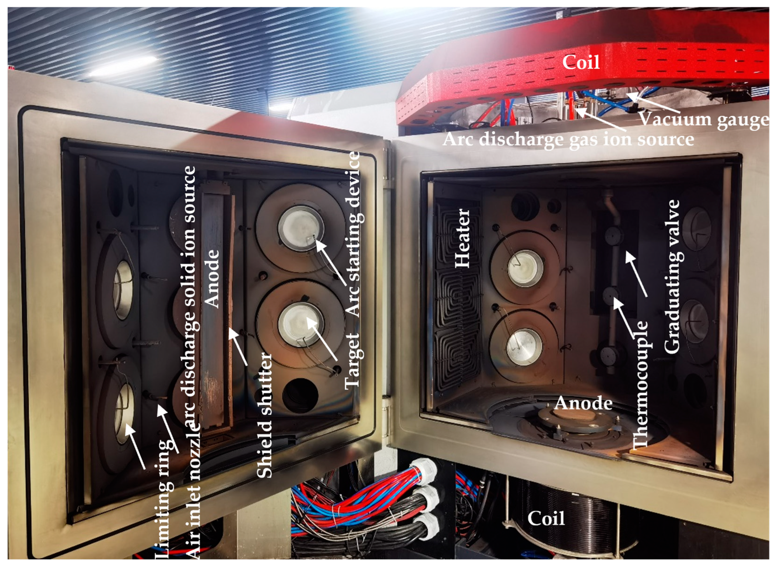
2.1. Coating Deposition

Figure 1 shows the structure diagram of the production-type arc ion plating coating machine. CrAlN and CrAlBN coatings are prepared on polished high-speed steel (S390) specimens (16 mm × 15 mm × 3 mm) and shaper cutters by home-made arc ion plating coating machine (as shown in Figure 1). The material of the shaper cutter is the same as that of the specimens, which is shown in Table 1. The arc ion plating coating machine is equipped with 8 vacuum arc sources and 3 vacuum arc etching sources. Al0.7Cr0.3 and Al0.63Cr0.27B0.1 targets were used to prepare CrAlN and CrAlBN coatings, respectively. After ultrasonic cleaning, the specimens and shaper cutter are armored to the workpiece frame to realize two-dimensional rotation. After the pressure of the vacuum chamber is pumped to 3.0 × 10⁻³ pa, the heating is turned on, and the temperature is kept at 500 °C for 60 min. Before etching the shaper cutter and specimens, Ar are first introduced into the vacuum chamber. After the pressure in the vacuum chamber is stable, the three arc ion sources start to work. Plasma etching was applied to the surface of the test piece and gear shaper cutter (the specific parameters are shown in Table 2). Plasma treatment can remove pollutants or low energy substances on the surface of the substrate, promote the activation of the surface of the substrate, and thus improve the surface energy and adhesion effect [43]. After the etching is completed, N2 is injected into the vacuum chamber, the coating is deposited after the pressure is stabilized at 3.5 Pa. To enhance the adhesion strength, CrAlN and CrAlBN adhesion layers are deposited with a target current of 130 A and bias voltage of −40 V, for 30 min. The working layers of CrAlN and CrAlBN are deposited with a target current of 130 A and bias voltage of −60 V, for 150 min. Table 3 lists the specific experimental parameters of the deposition of coatings.

2.2. Characterization

The wear marks, scratches and the edge wear of the coating were observed by Thermo Field Apreo 2C (Thermo Fisher Scientific, Waltham, MA, USA) scanning electron microscope (SEM). The friction and wear marks and the chemical composition of the edge were analyzed by Oxford Ultim Max X-ray (Oxford Instruments, Oxford, UK) energy spectrometer (EDS) equipped within the SEM. The phase characterization of the coating was conducted using X-ray diffraction (XRD, Bruker D8 Discover, Cu K α radiation (λ = 0.154056 nm)) with diffraction angles 2θ between 30° and 90°.
The microstructure of the coating was analyzed by Thermo Fisher Scientific (FEI) Talos F200s (Thermo Fisher Scientific, Waltham, MA, USA) ultra-high resolution field emission transmission electron microscope (TEM). The friction and wear behavior of coatings were evaluated using a normal temperature reciprocating friction and wear testing machine (Bruker’s Universal Mechanical Tester (UMT), Tribolab, Billerica, MA, USA). The test parameters included a load of 5 N, a speed of 2 Hz, and SiN balls with 6 mm diameters as the counterpart. The tribological tests were conducted continuously for a duration of 30 min. The cross-sectional area of the abrasion wear was measured using the Zygo (NewView9000, Middlefield, CT, USA) optical surface profiler. Anton Paar (Hit300) (Anton Paar, Graz, Austria) nanometer hardness tester was used to test the coated sample 9 times under a load of 10 mN. After excluding the singularity, the average value was calculated as the hardness and elastic modulus of the coating. The adhesion strength of the coating with substrate is evaluated by Anton Paar scratch meter (RST3), and the testing parameters are as follows, Beginning Load (mN): 1000, End Load (mN): 199999.99, Loading rate (mN/min): 397999.98, Scanning load (mN): 1000, Speed (mm/min): 6.

3. Results and Discussion

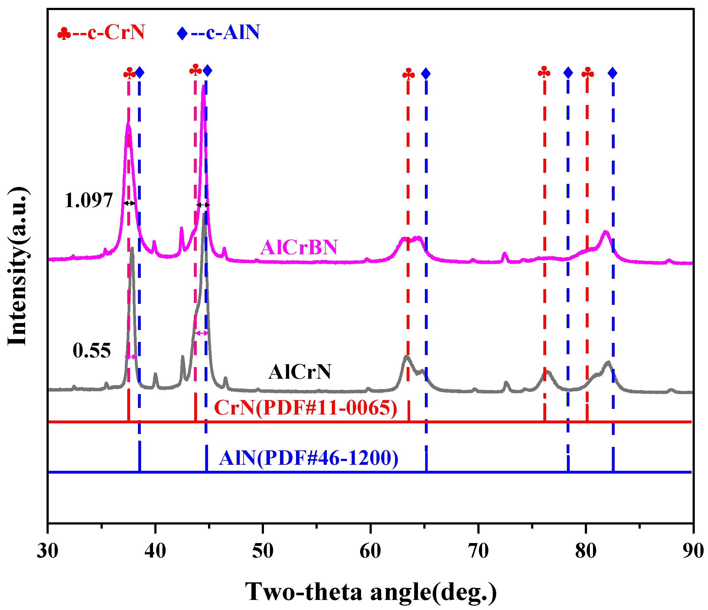
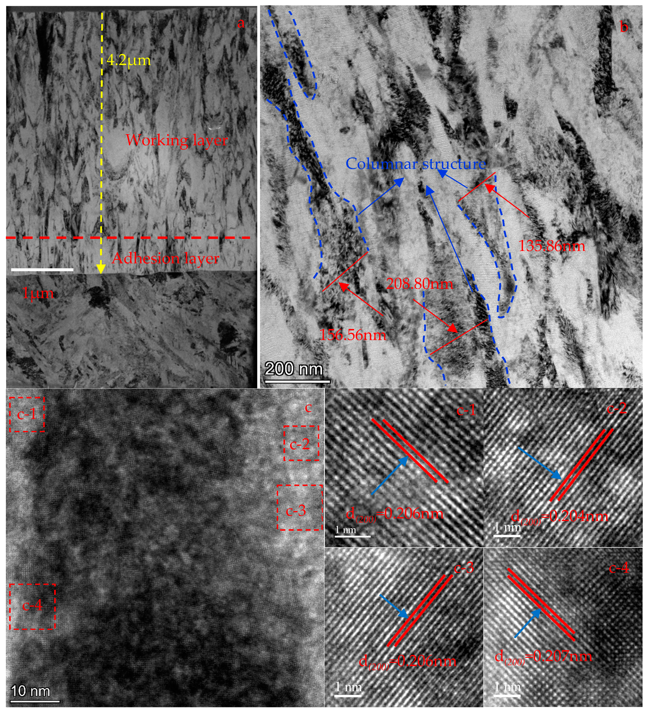
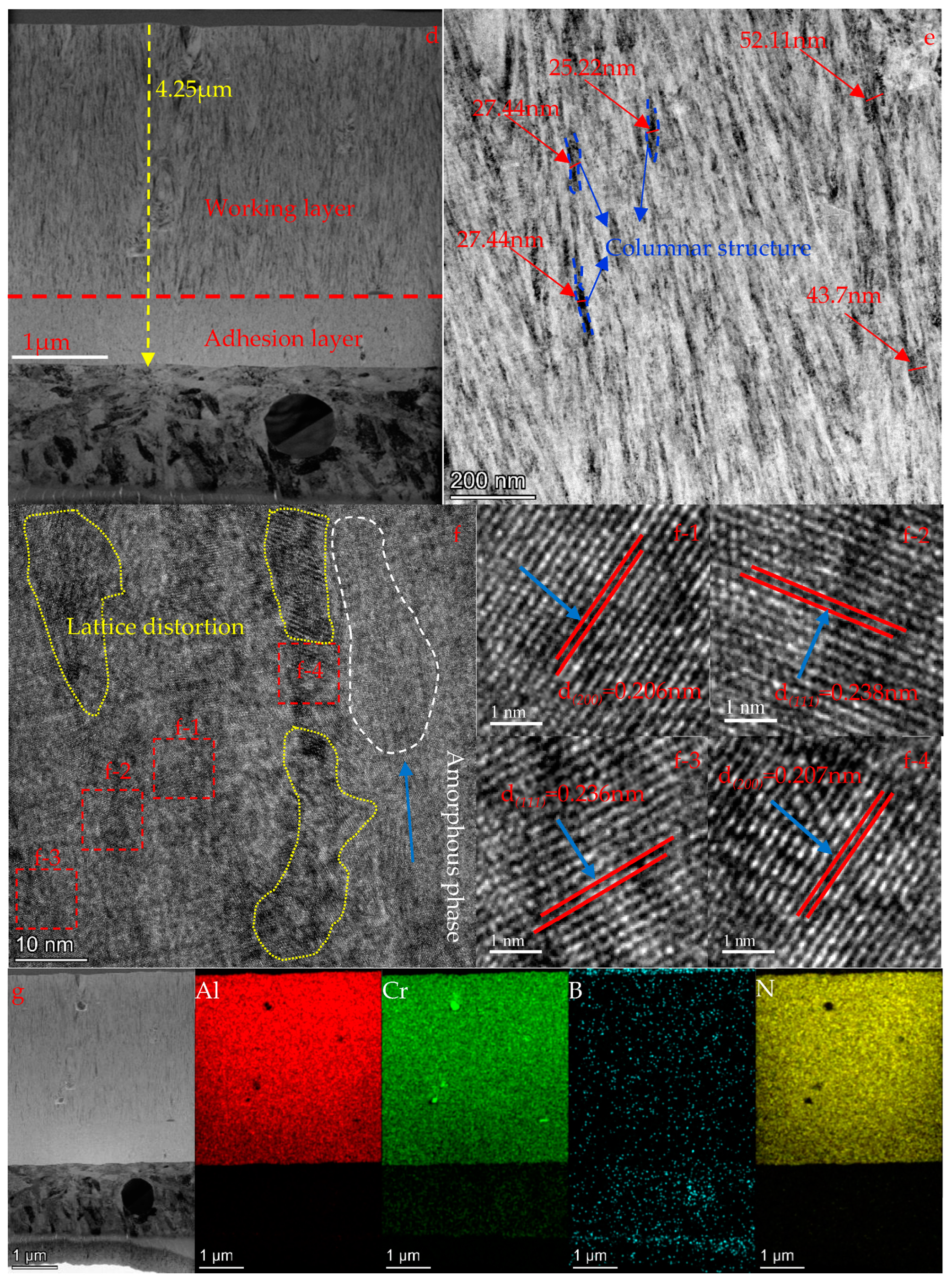
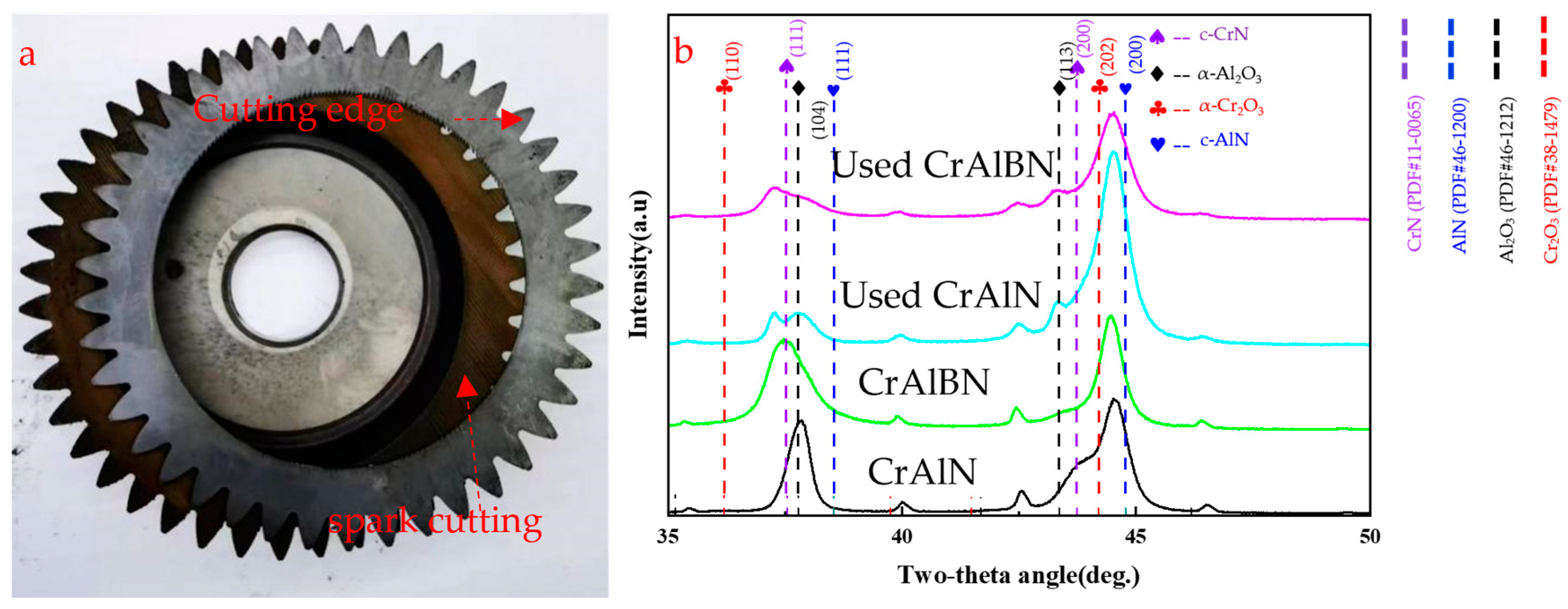
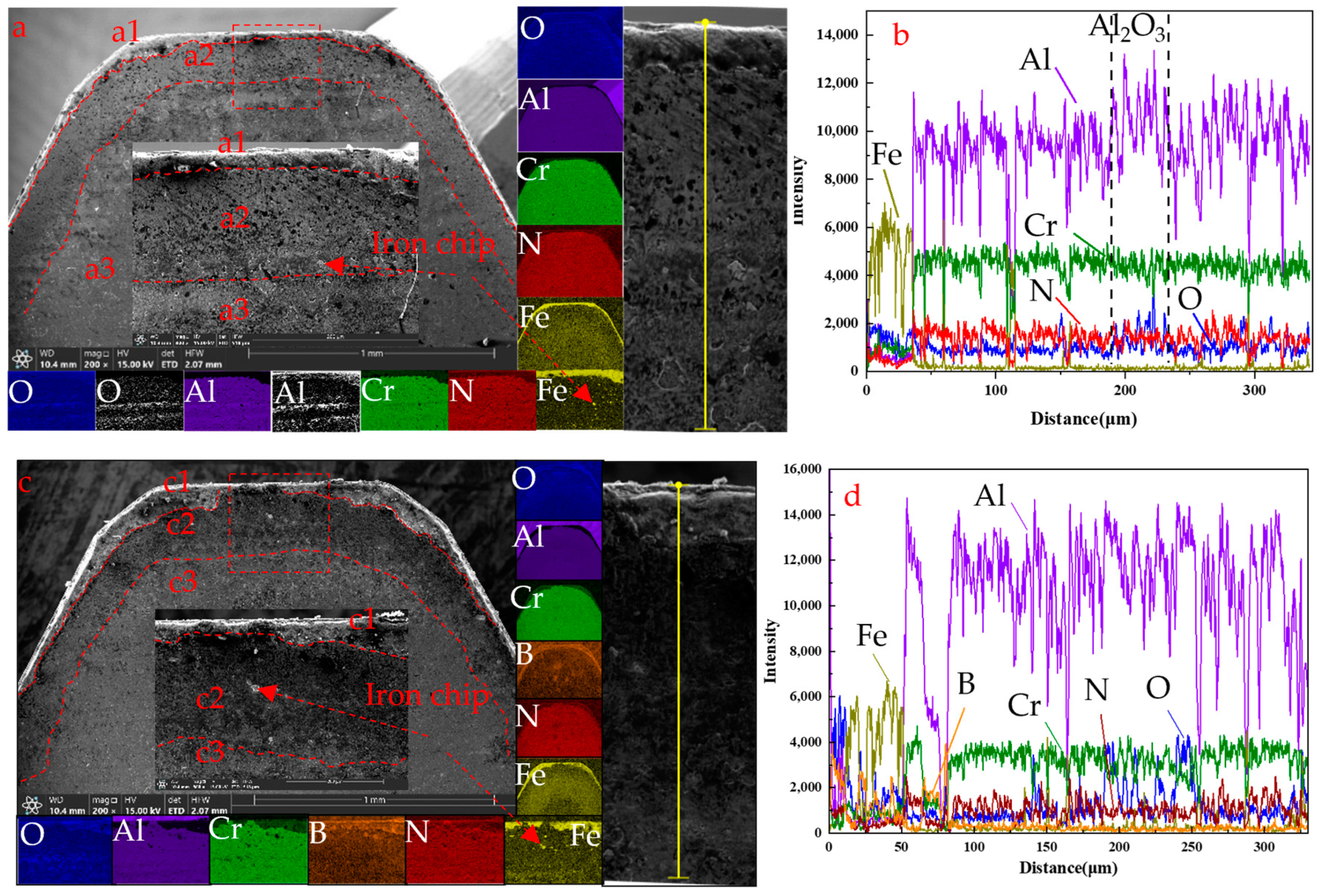
3.1. Composition, Structure and Morphology

Figure 2 shows the XRD patterns of CrAlN and CrAlBN coatings. It can be found that the position of the diffraction peak of CrAlN coating appears between the peaks of standard AlN (PDF#46-1200) and CrN (PDF#11-0065) with higher intensity, forming a metastable fcc-NaCl type structure of CrAlN, which is consistent with previous results [44,45].
From the XRD pattern of CrAlBN coating, it can be found that the peak (at the position of 37.8°) is shifted to a lower angle (about 37.5°), and the half-peak width changes from 0.55048 ± 0.01966° to 1.09719 ± 0.02582°. The Scherrer’s formula given in Equation (1) was used to calculate the average grain size (D) of the coatings. According to Scherrer’s formula, the average grain size of the coating decreases from 15.08 nm (CrAlN) to 7.51 nm (CrAlBN). Since the solubility limit of Al in the CrN lattice does not reach the of this component, the film structure is characterized by the metastable supersaturated fcc-AlxCr1−xN solid solution. The smaller B atoms are incorporated instead of larger Al and/or Cr atoms, and the solubility of the B atom in the fcc-AlxCr1−xN phase is limited, so the B atom will separate to the grain boundary, where it forms with the N and a-BNx phases, impeding the growth of crystals in the coating and the average grain size is reduced [34].
D = K γ β cos θ
where K is the Scherrer constant, γ is the wavelength of light used for the diffraction, β is the “full width at half maximum” of the sharp peaks, and θ is the angle measured. The Scherrer constant (K) in the above formula accounts for the shape of the particle and is generally taken to have the value of 0.89.
The Williamson–Smallman relation given in Equation (2) was used to calculate the dislocation density (δ) in nm−2 [46]. It can be calculated from Equation (2) that the dislocation density of the coating increases from 4.391 × 10⁻⁴ nm−2 (CrAlN) to 17.46710 × 10⁻⁴ nm−2 (CrAlBN).
δ = 1 D 2
The micro-strain (ɛ) was estimated with Equation (3). All the calculated results are given in Table 4 [47]. It can be calculated from Equation (3) that the micro-strain of the coating increases from 7.012 to 14.027.
ɛ = β c o t θ 4
From Table 4, it can be found that the micro-strain and dislocation density of CrAlN and CrAlBN coatings increase with the decrease of average grain size.
In order to further determine the effect of the addition of B element on the coating, the microstructure of the coating was studied in detail by transmission electron microscope (TEM). Some researchers analyzed the form of B element in CrAlBN coating by TEM according to SAED diffraction ring and found that when B content is 8 at.% [36] or 11 at.% [34], BN exists in the amorphous form in the CrAlBN coating. Figure 3 displays the TEM cross-section of CrAlN and CrAlBN coatings. Where panels a and d are the TEM bright-field images of CrAlN and CrAlBN coatings, respectively. According to a and d, it can be found that the thickness of CrAlBN coating increases from 4.2 μm to 4.25 μm compared with CrAlN coating. This is because the incorporation of light and small B atoms can reduce the bombardment intensity during deposition, thus decreasing the deposition surface and near-surface sputtering of the coating [48], and promoting the growth rate of the coating grains.
TEM bright-field images of CrAlN and CrAlBN (Figure 3b,e) show that both coatings present dense columnar structures, and the addition of B element reduces the columnar structure width of the coatings from 150–200 nm (CrAlN) to 10–50 nm (CrAlBN), and the maximum width of CrAlBN columnar structure is much smaller than that the maximum width of CrAlN coated columnar structure. Moreover, the addition of B element greatly improves the distribution uniformity of columnar structures in the coating. This corresponds to the broadening of XRD peaks in the XRD pattern of the coating before and after the addition of B element, which proves that the addition of B element makes the grain of the coating finer [39].
By comparing the HRTEM of CrAlN and CrAlBN coatings (Figure 3c,f), it was found that there were a large number of displacements, lattice bending and other defects along with contrast caused by internal stress in the CrAlBN coatings (Figure 3f). The crystals of BNx were not found in the HRTEM image (Figure 3f), instead, an amorphous phase was observed. Combining the XRD analysis results (Figure 2) with the cross section scanning results of the CrAlBN coating (Figure 3g), it can be determined that the B element and its compounds exist in the amorphous form in the CrAlBN coating.

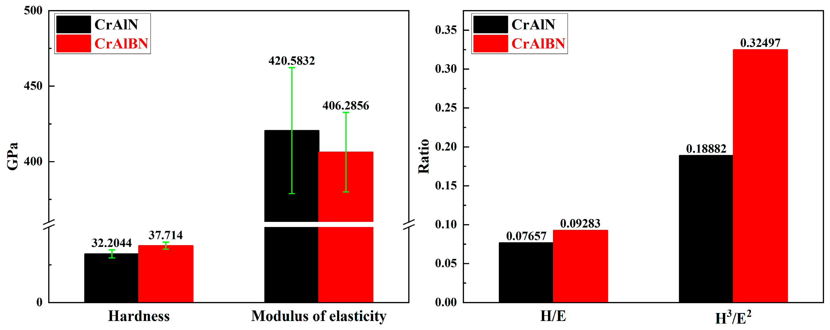
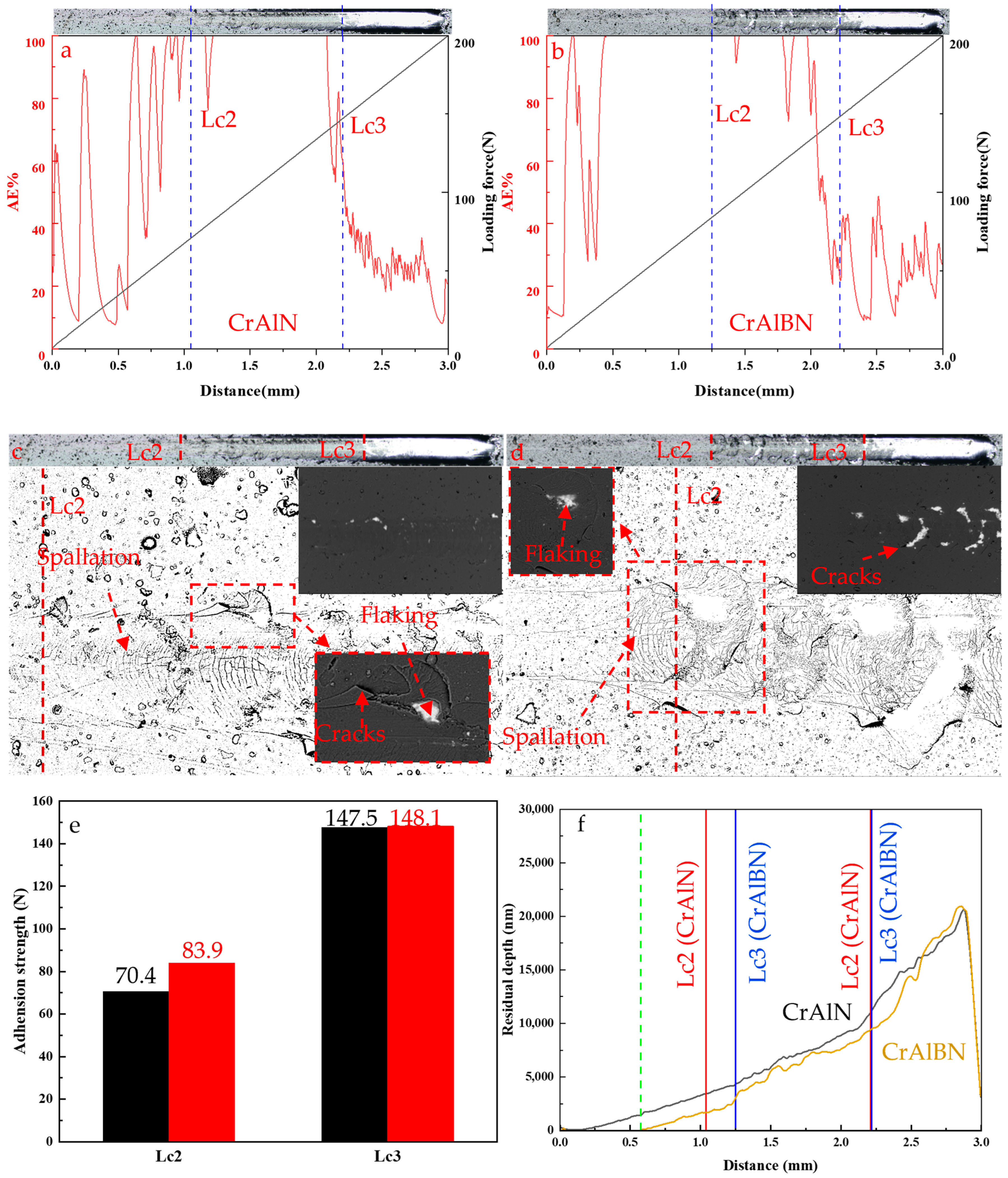
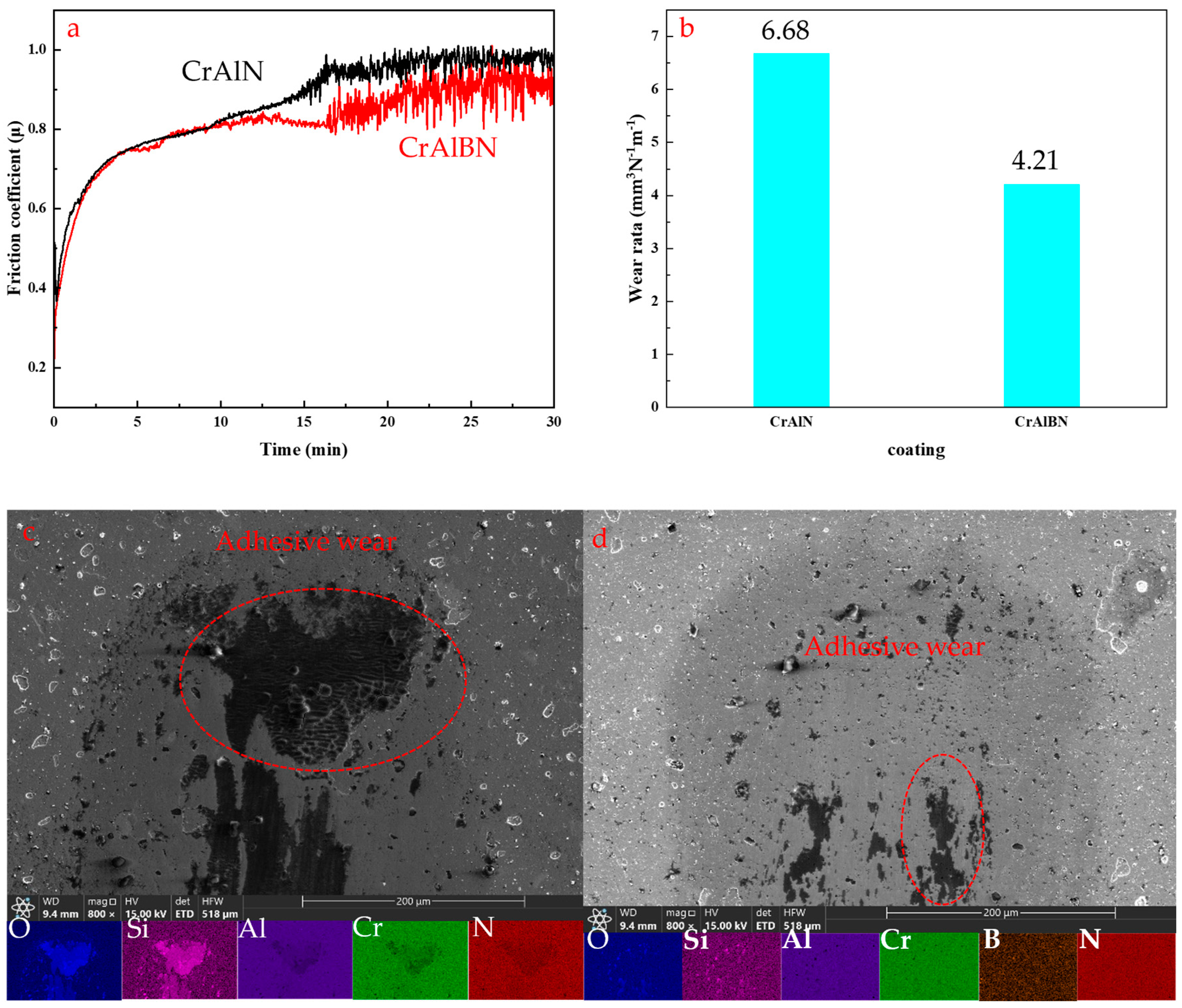
3.2. Mechanical Property

Figure 4 shows the hardness (H), elastic modulus (E), H/E and H3/E2 of CrAlN and CrAlBN coatings. After the addition of B element, the CrAlBN coating is subjected to the combined action of solid solution and Hall–Petch hardening [49], which increased the hardness from 32.2044 GPa (CrAlN) to 37.714 GPa (CrAlBN). This corresponds to the lattice distortion in the CrAlBN coating due to the incorporation of B element (Figure 3b). According to Scherrer’s formula, XRD pattern (Figure 2) and TEM bright field pictures of the coating before and after the addition of element B (Figure 3a,b), it can be seen that the addition of element B refines the grain of the coating. The elastic modulus decreased from 420.5832 GPa (CrAlN) to 406.2856 GPa (CrAlBN) due to grain refinement [50].
The ratio of H/E and H3/E2 value has been found to estimate film mechanical properties and predict coating protection function, which are very important parameters. H/E ratio is a parameter that reflects the elastic properties of the coating under external force, and it can be used to characterize the cracking and wear resistance of the coating [51,52]. Figure 4 shows the values for two coatings (CrAlN and CrAlBN). The CrAlBN coating has the highest H/E value (0.09283), which is closest to H/E = 0.1, indicating its potential to enhance the wear resistance of the coating [53]. The values of the H3/E2 determines the resistance of the coating to plastic deformation and is another importance parameter for the characterization of mechanical properties. H3/E2 reflects the ability of coating material to resist plastic deformation failure, and is suitable for evaluating the performance of coating in the plastic deformation stage [54,55]. The H3/E2 ratio for two coatings is 0.1882 GPa (CrAlN) and 0.32497 GPa (CrAlBN), respectively. The ratio of H3/E2 is proportional to the plastic deformation resistance of the film [56]. Results of the nano indentation properties characterization of the coatings showed that H/E and H3/E2 of the CrAlBN coating are higher than those of the CrAlN coating, which indicates that the addition of B element gives the CrAlBN coating a strong ability to resist elastic and plastic deformation.
In order to better evaluate the behavior of coatings adhesion strength, the Scratch test was used. The adhesion strength of CrAlN and CrAlBN coatings is shown in Figure 5. Among them, panels a and b are acoustic emission (AE) signals, load conditions and panoramic imaging images of scratches of CrAlN coating and CrAlBN coating respectively. Panels c and d are SEM images of scratches of CrAlN coating and CrAlBN coating, respectively. Panel e is the bar chart of the comparison of adhesion strength of the two coatings, and f is the contrast curve of scratch residual depth between the two coatings.
Combined with the panoramic image and SEM image of scratches, it can be determined that the cracking mode of the two coatings in the scratch test is conformal buckling cracking. In this way, the direction of the coating crack is consistent with the direction of the scratch, and the coating will not fall off a large area during the scratch process [57]. In the scratch test, Lc1, Lc2, Lc3 represent the critical load at which cracks begin to appear inside the scratch, the critical load at which the coating begins to fall off, and the critical load at which the coating completely falls off at the scratch, respectively [58,59]. Due to the interference of large particles and pits on the surface of the coating to the AE signal, the AE signal of the two coatings at Lc2 point is not obvious. The Lc2 critical load point of the coating can only be determined by the way of scratch morphology. The change position of the AE signal at Lc3 is consistent with the point where the coating completely falls off.
The adhesion strength of the coating is determined by the critical load of the coating at point Lc2 [59,60], it can be determined that the adhesion strength of coating at Lc2 increases from 70.4N (CrAlN) to 83.9N (CrAlBN) with the addition of element B (as shown in the Figure 5e). Compared with Cai et al.’s [41] method of coatings disposition, which uses multi-layer structural coating as adhesion layers and CrAlBN as working layers, the adhesion strength of coatings is improved. The increase of adhesion strength is due to deposition of adhesion layers at a lower bias voltage (−40 V), which can reduce residual compressive stress of the coating [61]. And the lower residual stress can enhance the adhesion strength between the coatings and the substrates [62].
As shown in the Figure 5f, it can be observed that the scratch surface of CrAlBN coating is mainly completely elastic deformation and the CrAlN coating undergoes significant plastic deformation in the initial stage of scratch test. Also, it can be observed that the residual depth of CrAlBN coating is obviously smaller than that of CrAlN coating, which indicates that CrAlBN coating has stronger resistance to plastic deformation than CrAlN coating. The above results correspond to the results of nanoindentation, further verifying that that the ratio of H3/E2 is proportional to the plastic deformation resistance of the film. The excellent performance of CrAlBN coating in coating thickness (Figure 3a,b), hardness (Figure 4), plastic deformation resistance and elastic deformation resistance can effectively delay the deformation at the coating/substrate interface, so that it has a high adhesion strength [40].
The friction coefficients and wear rates of AlCrBN coatings were measured at normal temperature (Figure 6). As shown in panel a in Figure 6, the friction coefficients of CrAlN and CrAlBN coatings are similar and stable at the initial wear stage. In the later wear stage, due to the interactions between wear debris and worn surfaces, the friction coefficient fluctuates greatly. During wear testing, an oxide film is formed at the contact zone between ball and coating, the shearing strength of B containing oxidation films usually show lower shearing strength in comparison to Al-containing or Cr-containing oxidation films, and also the hardness of CrAlBN is higher, so that CrAlBN coating has a lower coefficient of friction [40]. Compared with the AlCrN coating, the AlCrBN coating has a smaller grain size, which is also the reason why its friction coefficient is smaller than CrAlN [63].
The wear resistance of CrAlBN coating is better than that of CrAlN coating (Figure 6b). According to the morphology of the wear track in SEM images (Figure 6c,d), it can be found that there is an adhesive layer at the beginning of the wear track, which is similar to the results of Chang [64]. According to EDS analysis, the main components of the adhesive layers are Si and O elements. Combined with EDS analysis results and chemical composition (CrAlN and CrAlBN) of the coating working layers, it can be determined that adhesive layers come from counter-ball.
As shown in Figure 6a,b, micro-particles (MPs) and pits appear in the wear tracks and collapse occurred at the edge of the crater. The appearance of pits is caused by the defects of the coating itself. According to the EDS analysis results (Figure 6f,h), the particles are mainly Si and O elements, and also Si and O elements also appear at the edge of the pits. Si element is mainly from the counter-ball (SiN) used in the friction and wear experiment, and O element is mainly from the oxidation during the friction and wear process. MPs and the debris generated by pit collapse will participate in the grinding process of the coating and the grinding ball, and aggravate the wear of the coating. The results show that there are adhesive wear and abrasive wear in the process of friction and wear.

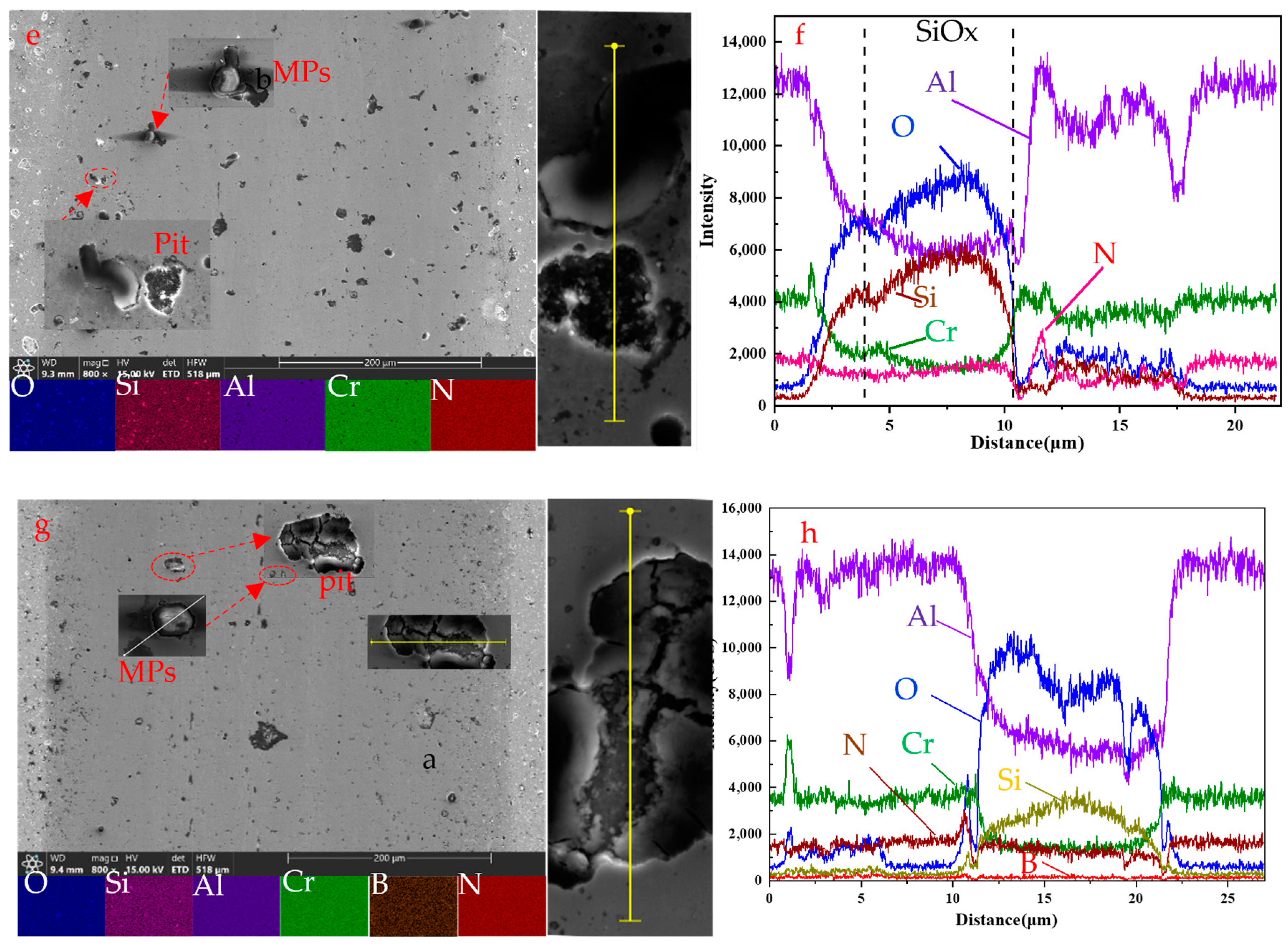
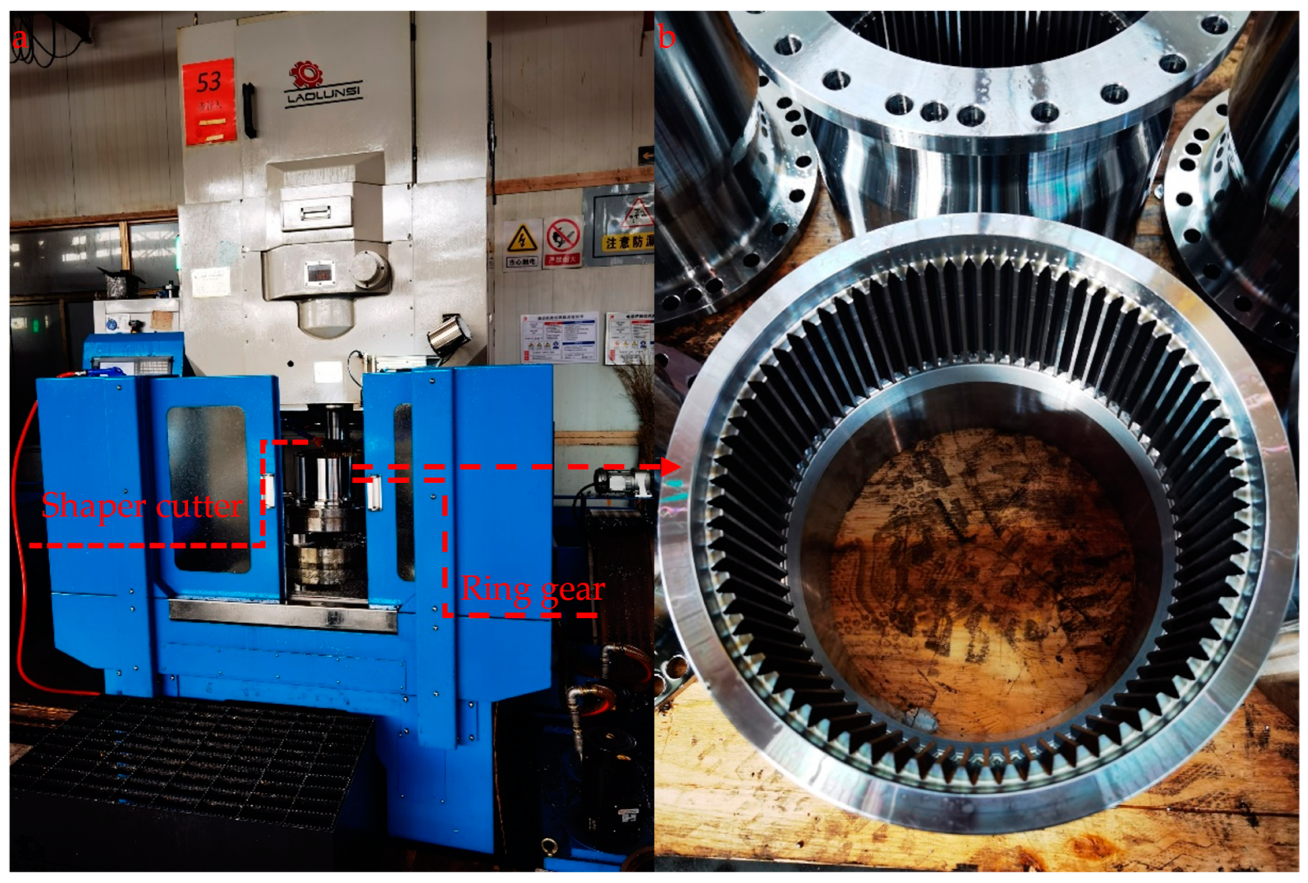
3.3. Cutting Performance

To study the basic properties of the coating better serves practical application. At the same time, the final cutting performance of the coating is the key to evaluate the coating quality. In this paper, the performance of CrAlN and CrAlBN coatings was tested on shaper cutter. The 20CrMnTi carburizing steel (after tempering treatment, its hardness is 280 HB) was used to evaluate these coated tools.
As shown in Figure 7a,b are the experimental setup (CNC machine tool (YL5150CNC) produced by Zhejiang Lawrence Machine Tool Co., Ltd., Taizhou, China) for cutting tests and the ring gear, respectively. Since the shaper cutter is a generating tool, the number of qualified gears processed by the tool is used as the criterion for judging the life of the coated tool. The gear processing parameters are shown in Table 5. The number of gears processed by coating tools is shown in Table 6. The CrAlBN coating has a higher service life than the CrAlN coating on the shaper cutter, which is consistent with the result of panel b in Figure 6.
The coated shaper cutter is shown in Figure 8a. In order to analyze the rake face of the gear shaper cutter, the Electrical Discharge Machining (EDM) cutting technology is used to separate the front face of the shaper cutter from the body of the tool. Unused coated tools and 20CrMnTi carburizing steel used to continuously cut 30 and 44 pieces, and XRD pattern of the rake face of these coated tools are shown in Figure 8b.
As shown in the Figure 8b, combined with the XRD pattern before and after the service of the coating (Figure 8b), it can be found that a relatively strong peak of Al2O3(113) occurs in the CrAlN coating at 37.7°. There is no oxide peak in the CrAlBN coating, which indicates that the oxidation wear of the CrAlN coating occurs during the service of the coating. In order to determine the wear behavior of the coatings during service, the rake face of the coated tools was analyzed.
As shown in panels a and c in Figure 9, from the partial enlargement and EDS analysis of rake face, it is found that coated tools could be divided into three regions: the unworn area (a3, c3); the area of unworn coatings (a2, c2), and the core worn area (a1, c1). According to EDS results, the Fe element can be detected on the rake face (a2, c2) of both coated tools, indicating that a diffusion wear mechanism existed in the cutting process [65].
The EDS mapping results of rake face (Figure 9a) shown high Al and O elements and the O and Al elements appear in the same position. However, oxides were not found in Figure 9c, showing that the oxidation wear of CrAlN coating occurred during the cutting process. This corresponds exactly to the result for panel b in Figure 8.
Figure 10a shows the cutting-edge morphology of CrAlN and CrAlBN coatings shaper cutter. It is clear that all coated shaper cutters present similar failure modes in the cutting-edge including boundary wear and edge damage because the shaper cutter is a forming processing tool. As such, boundary wear is the main reason for its failure. According to the SEM image of cutting-edge morphology of the CrAlN-coated shaper cutter (Figure 10a), it can be found that abrasive wear appears (a-1). Due to the high hardness of CrAlBN coating, the abrasive wear phenomenon of the CrAlBN-coated shaper cutter (b) has not been observed [64]. It can be found that the iron chip number of CrAlN-coated tools (a-2) is significantly greater than that of CrAlBN-coated tools (b-1), this indicates that the anti-diffusion wear performance of CrAlBN coating is better than that of CrAlN coating. The cracks (b-1) were only found in the CrAlBN coating, which is caused by the fatigue of the coating during the cutting process.

4. Conclusions

CrAlN and CrAlBN coatings were prepared on the surface of powder high speed steel and shaper cutter by arc ion plating technique. The effects of adding B element on the microstructure and mechanical properties of CrAlBN coating were studied systematically, as well as the service performance of the coated tools.
  • The addition of B element refines the grain of CrAlBN, improves the distribution uniformity of columnar structure, and causes lattice distortion of the coating, which improves the hardness, elastic deformation resistance and plastic deformation resistance of CrAlBN coating, and significantly improves the wear resistance.
  • The performance test of shaper cutter shows that CrAlBN coating significantly improves the edge wear resistance of the coating.
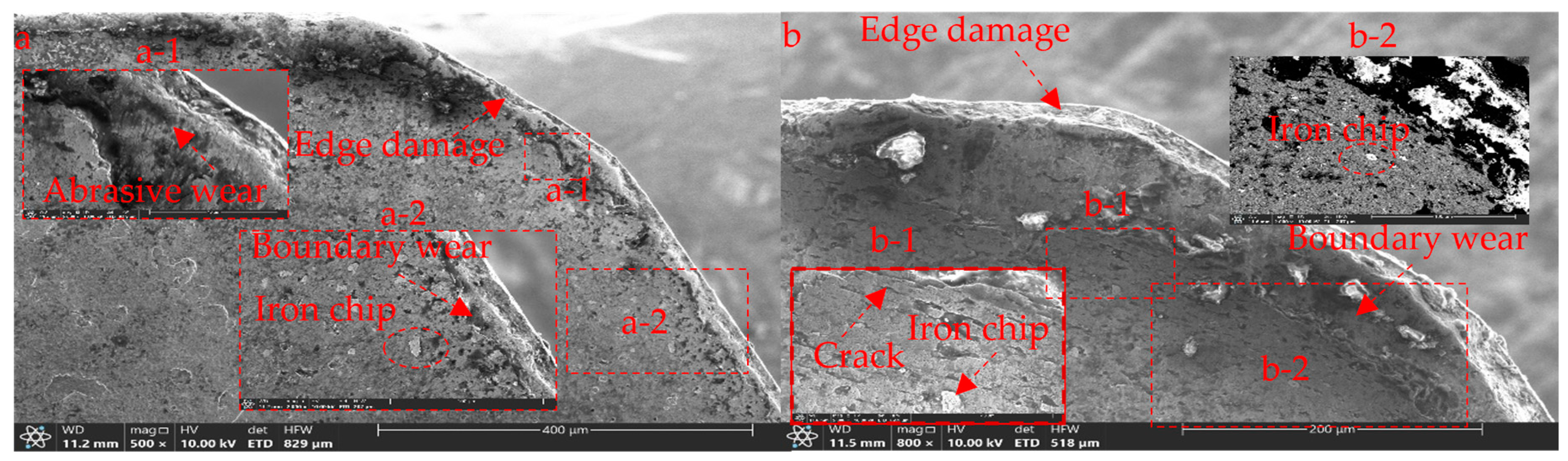
  • The wear mechanism of the coating changes significantly after adding B, and the comprehensive wear performance of the CrAlBN coating is better than that of the CrAlN coating. The study found that, in practical applications, edge damage is the main form of failure of coated shaper cutter. The CrAlN coating is mainly characterized by abrasive wear and diffusion wear, accompanied by oxidation wear. The CrAlBN coating is mainly fatigue wear, accompanied by a small amount of diffusion.

Author Contributions

Conceptualization, X.-L.L. and Z.L.; methodology, X.-L.L.; software, X.-L.L.; validation, F. S.; formal X.-L.L.; investigation, H.-J.Z.; resources, Z.L.; data curation, F.S.; writing—original draft preparation, X.-L.L.; writing—review and editing, Z.L.; visualization, H.-J.Z.; supervision, Z.L.; project administration, Z.L. and F.S.; All authors have read and agreed to the published version of the manuscript.

Funding

This work was supported by Chinese Academy of Sciences WEGO Research Development Plan, grant number [2017]006.

Institutional Review Board Statement

Not applicable.

Informed Consent Statement

Not applicable.

Data Availability Statement

Data are contained within the article.

Acknowledgments

The authors would like to thank NeuMat (Tai’an) Surface Technology Limited, Taian, China for supporting the experiments.

Conflicts of Interest

Xing-long Liu and Zeng Lin were employed by the company NeuMat (Tai’an) Surface Technology Limited. The remaining authors declare that the research was conducted in the absence of any commercial or financial relationships that could be construed as a potential conflict of interest.

References

  1. McNames, J. Fourier Series Analysis of Epicyclic Gearbox Vibration. J. Vib. Acoust. 2002, 124, 150–153. [Google Scholar] [CrossRef]
  2. Marco, C.; Antonella, C. Analysis of hybrid vehicle transmissions with any number of modes and planetary gearing: Kinematics, power flows, mechanical power losses. Mech. Mach. Theory 2021, 162, 104350. [Google Scholar] [CrossRef]
  3. Svahn, M. A parametric analysis of the surface roughness of teeth shaped by a pinion shaper cutter and guidelines for choosing process parameters. Proc. Inst. Mech. Eng. Part C J. Mech. Eng. Sci. 2019, 233, 7368–7377. [Google Scholar] [CrossRef]
  4. Kim, J.-D.; Kim, D.-S. Development of software for the design of a pinion cutter. J. Mater. Process. Technol. 1997, 68, 76–82. [Google Scholar] [CrossRef]
  5. Hidehiro, Y.; Shao, M.; Akira, I. Design and Manufacture of Pinion Cutters for Finishing Gears with an Arbitrary Profile. Trans. Jpn. Soc. Mech. Eng. Ser. C 1992, 35, 247–252. [Google Scholar] [CrossRef]
  6. Lai, H.-Y.; Wu, D.-S. An Enhanced DFM Model for Shaper Cutters. Int. J. Adv. Manuf. Technol. 2002, 19, 482–491. [Google Scholar] [CrossRef]
  7. Chang, S.-L.; Tsay, C.B. Computerized tooth profile generation and undercut analysis of noncircular gears manufactured with shaper cutters. J. Mech. Des. 1998, 120, 92–99. [Google Scholar] [CrossRef]
  8. Chen, C.-F.; Tsay, C.-B. Tooth profile design for the manufacture of helical gear sets with small numbers of teeth. Int. J. Mach. Tools Manuf. 2005, 45, 1531–1541. [Google Scholar] [CrossRef]
  9. Tsay, C.-B.; Liu, W.-Y.; Chen, Y.-C. Spur gear generation by shaper cutters. J. Mater. Process. Technol. 2000, 104, 271–279. [Google Scholar] [CrossRef]
  10. Bair, B.-W. Computerized tooth profile generation of elliptical gears manufactured by shaper cutters. J. Mater. Process. Technol. 2002, 122, 139–147. [Google Scholar] [CrossRef]
  11. Bouzakis, K.-D.; König, W.; Vossen, K. Use of powder metallurgical high-speed steel in gear hobbing and gear shaping. CIRP Ann.-Manuf. Technol. 1982, 31, 25–29. [Google Scholar] [CrossRef]
  12. Edward, H. The Wafer shaper cutter. Gear Technol. 1989, 26–28. Available online: https://www.geartechnology.com/articles/20959-the-wafer-shaper-cutter (accessed on 27 February 2024).
  13. Fritz, K.; Claus, K. Reducing production costs in cylindrical gear hobbing and shaping. Gear Technol. 2000, 17, 26–31. [Google Scholar]
  14. Kim, J.-S.; Kang, M.-C.; Ryu, B.-J.; Ji, Y.-K. Development of an on-line tool-life monitoring system using acoustic emission signals in gear shaping. Int. J. Mach. Tools Manuf. 1999, 39, 1761–1777. [Google Scholar] [CrossRef]
  15. Kühn, F.; Hendricks, S.; Troß, N.; Brimmers, J.; Bergs, T. Experimental analysis on the influence of the tool micro geometry on the wear behavior in gear hobbing. Int. J. Adv. Manuf. Technol. 2023, 126, 1279–1292. [Google Scholar] [CrossRef]
  16. Zhang, J.-J.; Liu, Z.-Q.; Du, J. Prediction of cutting temperature distributions on rake face of coated cutting tools. Int. J. Adv. Manuf. Technol. 2017, 91, 49–57. [Google Scholar] [CrossRef]
  17. Cho, I.-S.; Amanov, A.; Kim, J.-D. The effects of AlCrN coating, surface modification and their combination on the tribological properties of high-speed steel under dry conditions. Tribol. Int. 2015, 81, 61–72. [Google Scholar] [CrossRef]
  18. Dos Santos, J.A.B.O.; Sales, W.-F.; Santos, S.-C.; Machado, A.R.; da Silva, M.B.; Bonney, J.; Ezugwu, E.O. Tribological evaluation of TiN and TiAlN coated PM-HSS gear cutter when machining 19MnCr5 steel. Int. J. Adv. Manuf. Technol. 2007, 31, 629–637. [Google Scholar] [CrossRef]
  19. Kuzin, V.; Gurin, V.; Shein, A.; Kochetkova, A.; Mikhailova, M. The influence of duplex vacuum-plasma treatment on the mechanics of complex-profile cutting tool wearing in the production of aircraft engine parts (Article). Mech. Ind. 2018, 19, 704. [Google Scholar] [CrossRef]
  20. Mo, J.-L.; Zhu, M.-H.; Leyland, A.; Matthews, A. Impact wear and abrasion resistance of CrN, AlCrN and AlTiN PVD coatings. Surf. Coat. Technol. 2013, 215, 170–177. [Google Scholar] [CrossRef]
  21. Biava, G.; Siqueira, I.B.d.A.F.; Vaz, R.F.; de Souza, G.B.; Jambo, H.C.M.; Szogyenyi, A.; Pukasiewicz, A.G. Evaluation of high temperature corrosion resistance of CrN, AlCrN, and TiAlN arc evaporation PVD coatings deposited on Waspaloy. Surf. Coat. Technol. 2022, 438, 128398. [Google Scholar] [CrossRef]
  22. Mayrhofer, P.-H.; Willmann, H.; Reiter, A.-E. Structure and phase evolution of Cr-Al-N coatings during annealing. Surf. Coat. Technol. 2008, 202, 4935–4938. [Google Scholar] [CrossRef]
  23. Yang, S.; Cooke, K.-E.; Li, X.; McIntosh, F.; Teer, D.-G. CrN-based wear resistant hard coatings for machining and forming tools. J. Phys. D Appl. Phys. 2009, 42, 104001–104008. [Google Scholar] [CrossRef]
  24. Ren, X.-R.; Zhu, H.; Liu, M.-X.; Yang, J.-G.; Chen, H. Comparison of Microstructure and Tribological Behaviors of CrAlN and CrN Film Deposited by DC Magnetron Sputtering. Rare Met. Mater. Eng. 2018, 47, 1100–1106. [Google Scholar] [CrossRef]
  25. Shan, L.; Wang, Y.-X.; Zhang, Y.-R.; Miao, Q.; Xue, Q.J. Tribological performances of CrAlN coating coupled with different ceramics in seawater. Surf. Topogr. Metrol. Prop. 2017, 5, 034002. [Google Scholar] [CrossRef]
  26. Wang, L.-L.; Nie, X. Effect of Annealing Temperature on Tribological Properties and Material Transfer Phenomena of CrN and CrAlN Coatings. J. Mater. Eng. Perform. 2014, 23, 560–571. [Google Scholar] [CrossRef]
  27. Kawate, M.; Kimura, A.; Suzuki, T. Microhardness and Lattice Parameter of Cr1−xAlxN Films. J. Vac. Sci. Technol. A Vac. Surf. Film. 2002, 20, 569–571. [Google Scholar] [CrossRef]
  28. He, L.-Q.; Chen, L.; Xu, Y.-X.; Du, Y. Thermal stability and oxidation resistance of Cr1−xAlxN coatings with single phase cubic structure. J. Vac. Sci. Technol. Part A-Vac. Surf. Film. 2015, 33, 061513. [Google Scholar] [CrossRef]
  29. Lin, J.; Mishra, B.; Moore, J.-J.; Sproul, W.-D. A study of the oxidation behavior of CrN and CrAlN thin films in air using DSC and TGA analyses. Surf. Coat. Technol. 2008, 202, 3272–3283. [Google Scholar] [CrossRef]
  30. Reiter, A.-E.; Mitterer, C.; Sartory, B. Oxidation of arc-evaporated Al1−xCrxN coatings. J. Vac. Sci. Technol. A Vac. Surf. Film. 2007, 25, 711–720. [Google Scholar] [CrossRef]
  31. Willmann, H.; Mayrhofer, P.H.; Persson, P.O.; Reiter, A.E.; Hultman, L.; Mitterer, C. Thermal stability of Al-Cr-N hard coatings. Scr. Mater. 2006, 54, 1847–1851. [Google Scholar] [CrossRef]
  32. Nguyen, T.-D.; Kim, S.-K.; Lee, D.-B. Oxidation of nano-multilayered CrAlBN thin films between 600 and 1000 °C in air. J. Nanosci. Nanotechnol. 2010, 205, S373–S378. [Google Scholar] [CrossRef]
  33. Chang, C.L.; Huang, C.S.; Jao, J.Y. Microstructural, mechanical and wear properties of Cr–Al–B–N coatings deposited by DC reactive magnetron co-sputtering. Surf. Coat. Technol. 2011, 205, 2730–2737. [Google Scholar] [CrossRef]
  34. Tritremmel, C.; Daniel, R.; Lechthaler, M.; Polcik, P.; Mitterer, C. Microstructure and mechanical properties of nanocrystalline Al–Cr–B–N thin films. Surf. Coat. Technol. 2012, 213, 1–7. [Google Scholar] [CrossRef]
  35. Nose, M.; Chiou, W.-A.; Kawabata, T.; Hatano, Y.; Matsuda, K. Self-hardening effect of CrAlN/BN nanocomposite films deposited by direct current and radio frequency reactive cosputtering. Thin Solid Film. 2012, 523, 6–10. [Google Scholar] [CrossRef]
  36. Nose, M.; Kawabata, T.; Watanuki, T.; Ueda, S.; Fujii, K.; Matsuda, K.; Ikeno, S. Mechanical properties and oxidation resistance of CrAlN/BN nanocomposite coatings prepared by reactive dc and rf cosputtering. Surf. Coat. Technol. 2011, 205, S33–S37. [Google Scholar] [CrossRef]
  37. Kim, S.-K.; Le, V.-V. Deposition of nanolayered CrN/AlBN thin films by cathodic arc deposition: Influence of cathode arc current and bias voltage on the mechanical properties. Surf. Coat. Technol. 2010, 204, 3941–3946. [Google Scholar] [CrossRef]
  38. Le, V.-V.; Nguyen, T.-T.; Kim, S.-K. The influence of nitrogen pressure and substrate temperature on the structure and mechanical properties of CrAlBN thin films. Thin Solid Film. 2013, 548, 377–384. [Google Scholar] [CrossRef]
  39. Hu, C.; Chen, L.; Moraes, V. Structure, mechanical properties, thermal stability and oxidation resistance of arc evaporated CrAlBN coatings. Surf. Coat. Technol. 2021, 417, 127191. [Google Scholar] [CrossRef]
  40. Chen, W.-L.; Hu, T.; Hong, Y.; Zhang, D.-D.; Meng, X.-N. Comparison of microstructures, mechanical and tribological properties of arc-deposited AlCrN, AlCrBN and CrBN coatings on Ti-6Al-4V alloy. Surf. Coat. Technol. 2020, 404, 126429. [Google Scholar] [CrossRef]
  41. Cai, F.; Wang, J.-M.; Zhou, Q.; Xue, H.-P.; Zheng, J.; Wang, Q.-M.; Kim, K.-H. Microstructure evolution and high-temperature tribological behavior of AlCrBN coatings with various B contents. Surf. Coat. Technol. 2022, 430, 127994. [Google Scholar] [CrossRef]
  42. Okumiya, M.; Griepentrog, M. Mechanical properties and tribological behavior of TiN-CrAlN and CrN-CrAlN multilayer coatings. Surf. Coat. Technol. 1999, 112, 123–128. [Google Scholar] [CrossRef]
  43. Sharma, P.; Ponte, F.; Lima, M.-J.; Figueiredo, N.-M.; Ferreira, J.; Carvalho, S. Plasma etching of polycarbonate surfaces for improved adhesion of Cr coatings. Appl. Surf. Sci. 2023, 637, 157903. [Google Scholar] [CrossRef]
  44. Polcar, T.; Cavaleiro, A. High temperature properties of CrAlN, CrAlSiN and AlCrSiN coatings—Structure and oxidation. Mater. Chem. Phys. 2011, 129, 195–201. [Google Scholar] [CrossRef]
  45. Paksunchai, C.; Chantharangsi, C. CrAlN film hardness uniformity affected by nitrogen content. AIP Conf. Proc. 2020, 2279, 120006. [Google Scholar] [CrossRef]
  46. Williamson, G.-K.; Smallman, R.-E., III. Dislocation densities in some annealed and cold-worked metals from measurements on the X-ray debye-scherrer spectrum. Philos. Mag. 1956, 1, 34–46. [Google Scholar] [CrossRef]
  47. Khalid, H.-H.; Sarab, S.-J. Study the Lattice Distortion and Particle Size of One Phase of MnO by Using Fourier Analysis of X-ray Diffraction Lines. Adv. Phys. Theor. Appl. 2017, 65, 6–22. [Google Scholar]
  48. Mayrhofer, P.-H.; Willmann, H.; Hultman, L.; Mitterer, C. Influence of different atmospheres on the thermal decomposition of Al-Cr-N coatings. J. Phys. D Appl. Phys. 2008, 41, 155316. [Google Scholar] [CrossRef]
  49. Nieh, T.-G.; Wadsworth, J. Hall-petch relation in nanocrystalline solids. Scr. Metall. Mater. 1991, 25, 955–958. [Google Scholar] [CrossRef]
  50. Kim, H.-S.; Bush, M.-B. The effects of grain size and porosity on the elastic modulus of nanocrystalline materials. Nanostruct. Mater. 1999, 11, 361–367. [Google Scholar] [CrossRef]
  51. Leyland, A.; Matthews, A. On the significance of the H/E ratio in wear control: A nanocomposite coating approach to optimised tribological behaviour. Wear 2000, 246, 1–11. [Google Scholar] [CrossRef]
  52. Shtansky, D.-V.; Kiryukhantsev-Korneev, P.-V.; Bashkova, I.-A.; Sheveiko, A.-N.; Levashov, E.-A. Multicomponent nanostructured films for various tribological applications. Int. J. Refract. Met. Hard Mater. 2010, 28, 32–39. [Google Scholar] [CrossRef]
  53. Dong, M.-P.; Zhu, Y.-B.; Li, J.-L. Effect of amorphous phases induced by friction on wear resistance for TaN/ZrN coatings in thermal oxygen environment. Mater. Charact. 2023, 198, 112745. [Google Scholar] [CrossRef]
  54. Stewart, V.-A.; Brown, R.-H. The Interrelationship of Shear and Friction Processes in Machining Under Regenerative Chatter Conditions. In Proceedings of the Thirteenth International Machine Tool Design and Research Conference, Birmingham, UK, 18–22 September 1972; pp. 13–18. [Google Scholar] [CrossRef]
  55. Postolnyi, B.; Beresnev, V.-M.; Abadias, G.; Bondar, O.-V.; Rebouta, L.-M.-F.; Araújo, J.-P.; Pogrebnjak, A.-D. Multilayer design of CrN/MoN protective coatings for enhanced hardness and toughness. J. Alloys Compd. 2017, 725, 1188–1198. [Google Scholar] [CrossRef]
  56. Musil, J.; Jirout, M. Toughness of hard nanostructured ceramic thin films. Surf. Coat. Technol. 2008, 201, 5148–5152. [Google Scholar] [CrossRef]
  57. Bull, S.-J. Failure modes in scratch adhesion testing. Tribol. Int. 1997, 50, 25–32. [Google Scholar] [CrossRef]
  58. Liu, H.; Yang, F.-C.; Tsai, Y.-J.; Wang, X.-J.; Li, W.; Chang, C.-L. Effect of modulation structure on the microstructural and mechanical properties of TiAlSiN/CrN thin films prepared by high power impulse magnetron sputtering. Surf. Coat. Technol. 2019, 358, 577–585. [Google Scholar] [CrossRef]
  59. Cao, F.-Y.; Munroe, P.; Zhou, Z.-F.; Xie, Z.H. Mechanically robust TiAlSiN coatings prepared by pulsed-DC magnetron sputtering system: Scratch response and tribological performance. Thin Solid Film 2018, 645, 222–230. [Google Scholar] [CrossRef]
  60. Akhter, R.; Zhou, Z.-F.Z.; Xie, H.; Munroe, P. Enhancing the adhesion strength and wear resistance of nanostructured NiCrN coatings. Appl. Surf. Sci. 2021, 541, 148533. [Google Scholar] [CrossRef]
  61. Bobzin, K.; Brögelmann, T.; Maier, H.-J.; Heidenblut, T.; Kahra, C.; Carlet, M. Influence of residual stresses in hard tool coatings on the cutting performance. J. Manuf. Process. 2021, 69, 340–350. [Google Scholar] [CrossRef]
  62. Soroka, O.-B. Evaluation of residual stresses in PVD-coatings. Part 1. Review. Strength Mater. 2010, 42, 287–296. [Google Scholar] [CrossRef]
  63. Yazıcı, M.; Çomaklı, O.; Yetim, T.; Yetim, A.-F.; Çelik, A. Effect of sol aging time on the wear properties of TiO2–SiO2 composite films prepared by a sol–gel method. Tribol. Int. 2016, 104, 175–182. [Google Scholar] [CrossRef]
  64. Chang, C.-L.; Chen, W.-C.; Tsai, P.-C.; Ho, W.-Y.; Wang, D.-Y. Characteristics and performance of TiSiN/TiAlN multilayers coating synthesized by cathodic arc plasma evaporation. Surf. Coat. Technol. 2007, 202, 987–992. [Google Scholar] [CrossRef]
  65. Zhang, H.-D.; Mei, F.-S.; Yu, Y.; Lin, X.L.; Gao, J.-X. Improvement on the mechanical, tribological properties and cutting performance of AlTiN-based coatings by compositional and structural design. Surf. Coat. Technol. 2021, 422, 127503. [Google Scholar] [CrossRef]
Figure 1. Arc ion plating coating machine structure diagram.
Coatings 14 00486 g001
Figure 2. Illustrates the XRD patterns of CrAlN and CrAlBN coatings.
Coatings 14 00486 g002
Figure 3. (ag) Cross-section TEM images and surface scans of CrAlN and CrAlBN coatings.
Coatings 14 00486 g003aCoatings 14 00486 g003b
Figure 4. Hardness, elastic modulus, H/E and H3/E2 of CrAlN and CrAlBN.
Coatings 14 00486 g004
Figure 5. (af) The adhesion strength of CrAlN and CrAlBN and the morphology of scratches.
Coatings 14 00486 g005
Figure 6. Friction coefficient (a) and wear rates (b) of coatings. The SEM images and EDS analysis of the CrAlN coating wear tracks (c,e,f), and the CrAlBN coating wear tracks (d,g,h).
Coatings 14 00486 g006aCoatings 14 00486 g006b
Figure 7. Schematic illustration of experimental setup (a) and the ring gear (b).
Coatings 14 00486 g007
Figure 8. The coated shaper cutter (a), the XRD pattern of the rake face of the coated tool after service (b).
Coatings 14 00486 g008
Figure 9. SEM morphology, EDS analysis of the rake face of CrAlN coated tool (a,c) and CrAlBN coated tool (b,d).
Coatings 14 00486 g009
Figure 10. SEM images of the cutting-edge morphology of CrAlN (a) and CrAlBN (b) coating shaper cutter.
Coatings 14 00486 g010
Table 1. Chemical composition of specimens (S390) and shaper cutter.
ElementCCrMoVWCoFeOther
wt%1.644.802.004.8010.408.0067.460.9
Table 2. Plasma etching process.
ProcedureBias Voltage/VAr/sccmH2/sccmCurrent/ATemperature/°CDeposition Time/min
Ti
15010008048015
21401001008048015
3140100010048030
41501000100480150
Table 3. CrAlN and CrAlBN coating deposition parameters.
ProcedureBias Voltage/VN2 Partial Pressure/PaCurrent/ATemperature/°CDeposition Time/min
Al0.7Cr0.3Al0.63Cr0.27B0.1
CrAlN (1)403.5130 48030
CrAlN (2)1503.5130 480150
CrAlBN (1)403.5 13048030
CrAlBN (2)1503.5 130480150
Table 4. The average grain size (D), dislocation density and micro-strain of the coatings.
NoCoating2θ (Degree)FWHM (β)°D (nm)Dislocation Density
δ (×10−4 nm−2)
Micro-Strain ε (×10−3)
1CrAlN37.8°0.550415.084.3917.012
2CrAlBN37.5°1.09717.5117.46714.072
Table 5. The gear processing parameters.
ProcedureModulus(M)Stroke
(mm)
Number of Strokes (str/min)Circumferential Feed (mm/str)Radial Feed (mm/str)
13100900.30.02
231001000.40.02
331001100.50.02
Table 6. The number of gears processed by coating tools.
CoatingNumber of Gears Processed (pieces)
CrAlN30
CrAlBN44
Disclaimer/Publisher’s Note: The statements, opinions and data contained in all publications are solely those of the individual author(s) and contributor(s) and not of MDPI and/or the editor(s). MDPI and/or the editor(s) disclaim responsibility for any injury to people or property resulting from any ideas, methods, instructions or products referred to in the content.

