Article

Melamine-Modified Graphene Oxide as a Corrosion Resistance Enhancing Additive for Waterborne Epoxy Resin Coatings

1
College of Chemistry and Chemical Engineering, Inner Mongolia University, Hohhot 010021, China
2
Inner Mongolia Key Laboratory of Graphite and Graphene for Energy Storage and Coating, School of Materials Science and Engineering, Inner Mongolia University of Technology, Hohhot 010051, China
*
Authors to whom correspondence should be addressed.
Coatings 2024, 14(4), 488; https://doi.org/10.3390/coatings14040488
Submission received: 27 March 2024 / Revised: 11 April 2024 / Accepted: 12 April 2024 / Published: 16 April 2024
(This article belongs to the Section Corrosion, Wear and Erosion)

Abstract

:
Waterborne epoxy resin (WEP) coatings are widely used in various fields due to their environmentally friendly properties, yet their corrosion resistance and shielding properties demand further refinement. In this work, melamine-modified graphene oxide (MGO) was synthesized using surface covalent functionalization, and a novel waterborne epoxy/modified graphene oxide coating (WEP/MGO) was prepared. The optimal modification effect was obtained by exploring different proportions of melamine, which led to significant improvements in the corrosion resistance of WEP. Furthermore, the corrosion protection efficiency of WEP/MGO coatings was systematically evaluated by examining the impact of different additions of MGO. The impedance modulus at the lowest frequency was increased from 3.77 × 10⁸ Ω·cm2 of WEP to 2.85 × 10⁹ Ω·cm2 after immersion in 3.5% NaCl for 48 h, when the addition of MGO was 0.1 wt.%. And the corrosion expansion at both the scratch and corrosion spot frequencies of the WEP-coated samples displayed a remarkable attenuation following exposure to salt spray for 300 h. The corrosion resistance and barrier properties of WEP coatings have been considerably enhanced.

1. Introduction

Corrosion infiltrates every aspect of our existence, earning its moniker as the “metallurgical ailment” and the “clandestine assailant”. Numerous fields grapple with a wide array of corrosion issues, and it is one of the main causes of failure of metallic equipment and has long been a much-vexed issue in anticorrosion fields [1,2,3,4]. Anticorrosive coatings have the performance of durability, low cost, and high protection [5,6,7]. However, the application of traditional solvent-based epoxy coatings results in the emission of significant quantities of volatile organic compounds (VOCs), thereby posing a discernible risk to human health and environmental well-being [8]. Furthermore, traditional coatings’s anti-corrosion efficacy is compromised by the presence of hydrophilic groups [9,10]. These issues highlight the need for further research and development to optimize the performance and environmental impact of the coatings. Waterborne coatings are more industrially appealing for corrosion protection due to their low toxicity [11]. Waterborne epoxy resin (WEP) is a kind of thermosetting resin that has exceptional adhesion, anti-corrosion properties, and is environmentally friendly. WEP corrosion protective coatings have gained unanimous approval for their exceptional efficacy in roof waterproofing, bridge construction, marine vessels, tunnel infrastructure, and various other domains. Nevertheless, some micro-holes and cracks will occur during the curing process of WEP coatings, which leads to a reduction in the anti-corrosive properties of the coatings. The long-term corrosion resistance and durability of WEP coatings may be compromised. One of the effective methods for improving the corrosion resistance of the WEP coating is adding nanopigments [12,13].
In recent times, the incorporation of inorganic nanomaterials has emerged as a pivotal strategy in coating technology [14,15]. These nanomaterials play a crucial role in enhancing the performance and functionality of coatings [16,17,18,19]. Chen et al. were successful in improving the corrosion resistance of metals through the utilization of a cleverly designed conductive polypyrrole (PPy) coating, which had been modified using molybdate-loaded TiO2 nanotubes [19]. Ma et al. developed an innovative composite nanoparticle (CNP) coating by incorporating a 1-hydroxybenzotriazole inhibitor into mesoporous silica nanocontainers. Their study demonstrated the effective inhibition of copper corrosion as a result [20]. Nevertheless, the loose structure of nano-inorganic materials leads to a weak physical barrier and subsequently results in poor barrier effectiveness. Graphene and graphene oxide (GO), as an emerging two-dimensional nano-carbon material, have attracted extensive attention from researchers in various fields due to their unique specific surface area and excellent corrosion resistance and insulation properties [21,22,23,24]. Ning et al. successfully synthesized dodecyl benzene sulfonic acid-PANI/phosphorylated graphene oxide (DPPGO) and consequently achieved anticorrosive coatings with exceptional properties [25]. Nonetheless, GO is susceptible to agglomeration, tending to aggregate within epoxy resin, consequently impacting the corrosion resistance [26]. To enhance the compatibility of GO with solvents and polymers, covalent or non-covalent functionalization methods can be employed. The surface of GO contains various functional groups, such as hydroxyl and epoxide groups that are spread across the basal planes, as well as carboxyl and carbonyl groups located on the edge sites [27,28,29]. These functional groups provide potential sites for chemical reactions and interactions, allowing for improved compatibility with solvents and polymers when appropriately modified. Covalent functionalization involves the covalent bonding of molecules to the functional groups on GO, while non-covalent functionalization relies on non-covalent interactions, such as π-π stacking or hydrogen bonding. These functionalization strategies aim to enhance the dispersion and adhesion of GO within the polymer matrix, leading to improved performance in terms of mechanical properties, electrical conductivity, and corrosion resistance. Li et al. prepared aniline oligomer-functionalized graphene oxide (AOFG) and reduced graphene oxide (AOFrG) via a liquid-phase chemical modification route and incorporated them into the polyurethane (PU) by in situ polymerization to obtain both wear-resistant and anticorrosive composite coatings [30]. Wu employed hexagonal boron nitride to enhance the compatibility between hexagonal boron nitride and waterborne epoxy resin through non-covalent modification of GO [31]. However, until now, no comprehensive investigation has been conducted regarding the utilization of modified graphene oxide (MGO) as a reinforcing agent in waterborne coatings for corrosion protection using melamine as a modifier.
In this work, we present a simple and cost-effective method for the synthesis of melamine-modified GO through surface covalent functionalization. An investigation was conducted on the impact of the melamine-to-GO reaction ratio on the structural characteristics of the MGO. The resulting MGO exhibits excellent anti-corrosion properties, making it a promising candidate as a filler material for protective coatings. We further prepared WEP/MGO composite coatings via a two-step synthesis process and investigated the impact of the amount of MGO added on the corrosion protection performance of the WEP coatings. These findings offer invaluable insights into the investigation of corrosion mitigation in high-performance waterborne coatings. The incorporation of a composite filler comprising melamine and GO has proven to be highly effective in enhancing the anti-corrosion performance of the coating. This innovative approach holds great promise for improving the anti-corrosion capabilities of coatings, thereby stimulating further exploration into novel filler materials and their potential applications in protective coatings.

2. Experiment

2.1. Experimental Materials

The GO utilized in the study was sourced from Dasheng Graphite New Materials Co., Ltd. (Ulanqab, China), while the waterborne epoxy emulsion (JH-5560-A, 200~220 g/mol) and waterborne epoxy curing agent (JH-5560-B, 180~190 mg KOH/g) were procured from Shanghai Jiuyou Chemical Technology Co., Ltd. (Shanghai, China). Melamine (AR) was acquired from Shanghai Macklin Biochemical Technology Co., Ltd. (Shanghai, China). Q235 steel (150 mm × 100 mm) primarily consists of the following components: Mn: 0.41 wt.%, Si: 0.28 wt.%, P: 0.033 wt.%, S: 0.047 wt.%, C: 0.17 wt.%, and Fe: balance. The water utilized in the experiments was obtained using a UPD-Ⅱ-20T water system. Additionally, all reagents were used as received without the need for further purification.

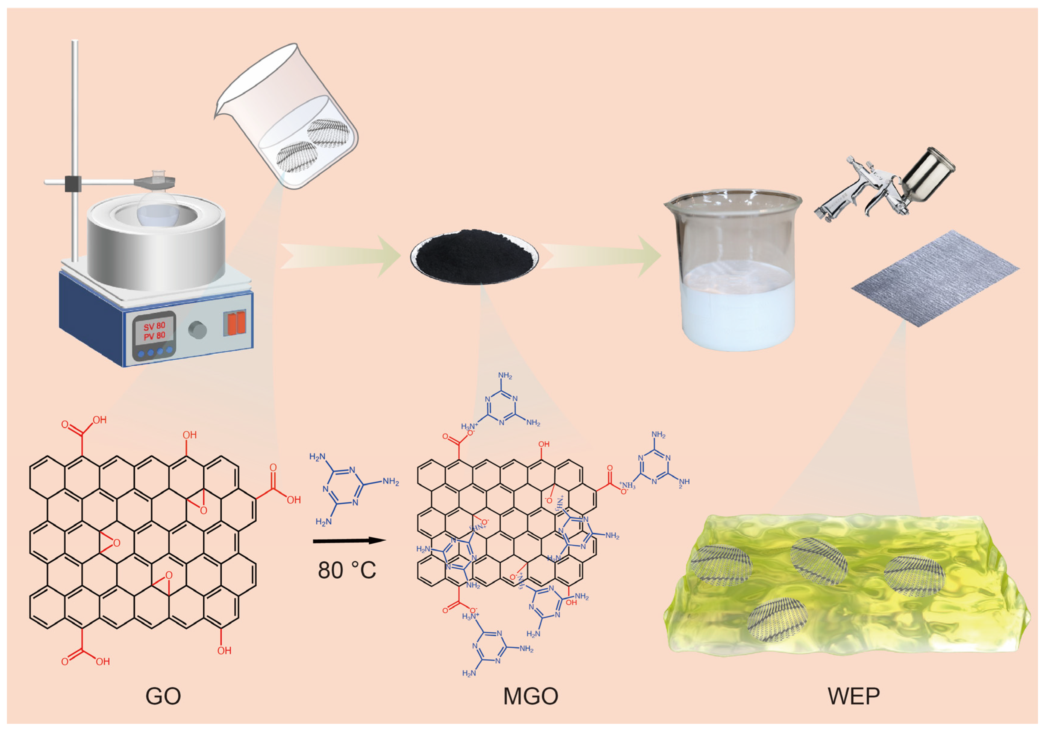
2.2. Preparation of Melamine-Modified Graphene Oxide

Melamine was grafted onto GO flakes using a one-step method. The specific process is as follows: to begin, weigh a suitable quantity of GO and transfer it into a beaker. Add 50 mL of ultrapure water to the beaker containing GO and proceed to sonicate the mixture for 1 h. This will help achieve a uniformly dispersed mixture of GO in water. Subsequently, take an appropriate amount of melamine and add it to 20 mL of ultrapure water in a separate container. Apply heat and stir the mixture until the melamine is completely dissolved, resulting in an aqueous melamine solution. The GO dispersion and the melamine aqueous solution were combined at a mass ratio of 5:1 and stirred at 80 °C for 40 min to ensure thorough mixing. The resulting MGO solution was then transferred to an evaporator and subsequently dried in a constant-temperature drying oven at 60 °C. After grinding the mixture into a powder, it was set aside for future use. Additionally, as part of the experimental setup, control samples were prepared using different mass ratios of GO dispersion in an aqueous melamine solution. Specifically, ratios of 5:0.5 and 5:1.5 were used to investigate the characteristics of MGO with varying melamine additions, aiming to determine the optimal ratio for the desired properties. Figure 1 the synthesis process of MGO was illustrated graphically.

2.3. Preparation of WEP/MGO Composite Coatings

Firstly, 0.05%, 0.1%, 0.2%, and 0.3% MGO of WEP mass were dispersed in ultrapure water. After ultrasonic 1 h, 2 g of WEP and 1 g of curing agent were mixed. The resulting mixture was stirred thoroughly to attain a well-mixed composite coating. To attain sprayable consistency and enable viscosity adjustment, the curing agent was introduced into the composite coating for the Q235 sample. The resulting mixture was thoroughly stirred to ensure a homogeneous blend of the composite coating. Subsequently, the epoxy composite coating was sprayed onto the Q235 steel substrate after appropriate pretreatment. The coated samples were subjected to a curing process in a drying oven maintained at a temperature of 80 °C for 12 h. The thickness of the coating after curing and simultaneous curing was measured to be 100 ± 10 μm. Furthermore, to facilitate comparison, reference samples of Q235 were coated with a waterborne epoxy composite. Figure 1 the synthesis process of WEP/MGO was illustrated graphically.

2.4. Characterization

The modification of both GO and MGO was evaluated using various analytical techniques. X-ray diffraction (XRD) analysis was conducted using a D/MAX-2500/PC instrument (Rigaku, Tokyo, Japan) with Cu Kα radiation operating at 30 kV and 35 mA. Fourier transform infrared spectroscopy (FTIR) was obtained by the Bruker TENSOR II spectrometer (Bruker, Karlsruhe, GERMANY), and the scanning range was 4000–500 cm−1. The solid powder sample was mixed with a small amount of potassium bromide powder, and the mixed powder was fined and pressed into tablets for infrared spectroscopy. Raman spectra were obtained by a Horiba IHR320 spectrometer (Horiba, Kyoto, Japan) with a scanning range of 100–4000 cm−1 and an excitation wavelength of 532 nm. The solid powder was dispersed in ethanol and dried on a glass slide for Raman spectroscopy. The morphologies of both GO and MGO were examined using scanning electron microscopy (SEM) with an FEI QUANTA 650 instrument (FEI, Hillsboro, OR, USA). Additionally, transmission electron microscopy (TEM) analysis was performed using a JEOL 2100 microscope (JEOL, Tokyo, Japan) to further investigate the microstructure of GO and MGO.

3. Results and Discussion

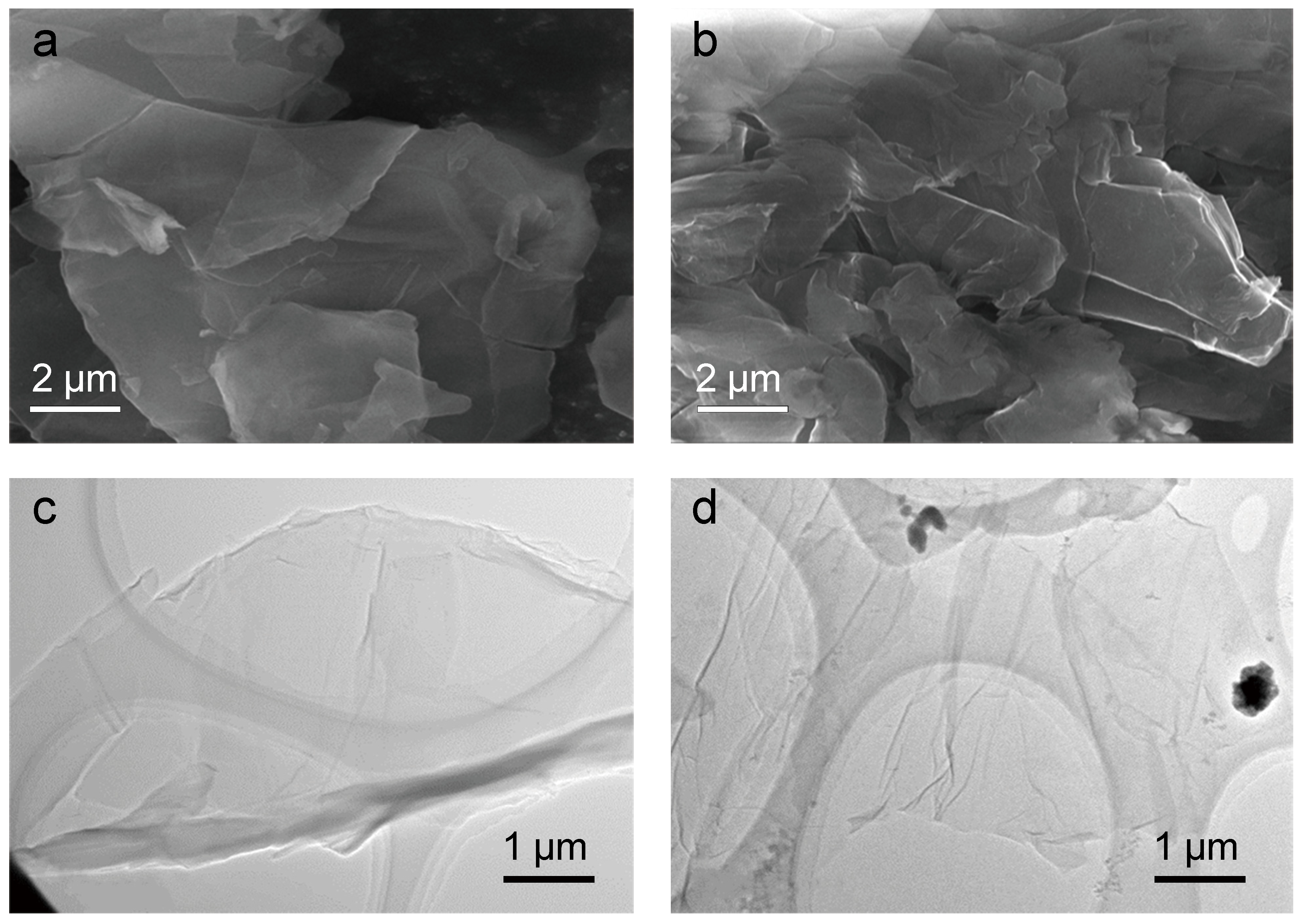
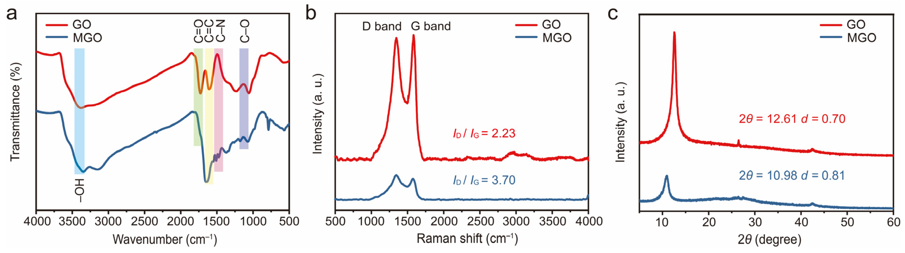
3.1. Characterization of GO and MGO

In order to determine the optimum mass ratio of melamine to GO, a series of experiments were conducted, incorporating FTIR, XRD, and Raman spectroscopy analyses on both GO and MGO samples with varying ratios of melamine. The characteristic peaks of GO at 3379 cm−1, 1728 cm−1, 1632 cm−1, and 1067 cm−1 are attributed to the stretching vibrations of –OH, C=O, C=C, and C–O–C, respectively [32,33]. At the mass ratio of 5:0.5, there is no C–N characteristic peak at 1510 cm−1, and the intensity of the C=O peak at 1728 cm−1 is not significantly reduced, suggesting that modification is difficult to achieve with a small amount of added melamine. At the mass ratio of 5:1, the characteristic peak of C–N appears at 1510 cm−1, and the intensity of the C=O peak at 1728 cm−1 is significantly reduced, indicating successful modification of GO (Figures S1 and S2). In comparison with GO, the adsorption intensity of the epoxide group at 1067 cm−1 and the carboxyl groups at 1728 cm−1 exhibited a significant decrease after modification. This decrease can be attributed to the amino group of melamine being covalently grafted with the carboxyl group of GO and the ring-opening reaction with the epoxide group of GO. At the mass ratio of 5:1.5, in addition to the characteristic peak of C–N at 1510 cm−1, there are also some miscellaneous peaks of melamine, suggesting that excessive melamine has been added. Overall, these results suggest that the best effect is obtained when the GO dispersion and the melamine aqueous solution react at a mass ratio of 5:1, and the FTIR spectra are presented in Figure 2a.
Raman spectra were used to compare the degree of confusion and disorder in GO and MGO samples with varying ratios of melamine. The ID/IG value of GO was measured to be 2.23, with the D band appearing at 1347 cm−1 and the G band at 1596 cm−1. Similar observations were performed for MGO with different reaction ratios, where the D band and G band were also observed around 1347 cm−1 and 1596 cm−1, respectively. This indicates that the basic carbon lattice structure of GO was not significantly altered by the modification process [34]. When considering the mass ratios of 5:0.5, 5:1, and 5:1.5, it was observed that their corresponding ID/IG values amounted to 2.52, 3.70, and 2.90, respectively. Interestingly, when the mass ratio of GO dispersion and melamine aqueous solution was 5:1, the ID/IG value was the highest (Figure S3). This suggests that the structural confusion and disorder within MGO are maximized at this ratio, resulting in the most effective melamine modification (Figure 2b).
The XRD spectra of GO and MGO samples with varying ratios of melamine were compared and presented in Figure S4. To mitigate the effects of external factors on peak shifting, nanosilica (20 wt.%) was introduced into the GO and MGO samples. GO exhibits a high-intensity diffraction peak at 12.61°, indicating an interlayer spacing of 0.70 nm. Functional groups, such as hydroxyl and epoxy groups, are attached to the surfaces of GO, leading to the expansion of the interlayer spacing. These functional groups are responsible for the enhanced hydrophilicity and increased reactivity of GO compared to graphite [35]. Indeed, the increase in interlayer spacing observed in MGO compared to GO can be attributed to the reaction of the amino group on melamine with the carboxyl group and epoxide group on the graphene oxide sheet. When the mass ratio is 5:0.5, a high-intensity diffraction peak appears at 11.93°, and the interlayer spacing is 0.74 nm. This can be attributed to the infiltration of a small amount of ungrafted melamine molecules into the GO sheet layer, resulting in a slight increase in the interlayer spacing of MGO. At the mass ratio of 5:1, a high-intensity diffraction peak occurs at 10.98° with an interlayer spacing of 0.81 nm. Indicating successful grafting of a large amount of melamine onto the GO and resulting in an increased interlayer spacing of MGO. When the mass ratio is 5:1.5, a high intensity diffraction peak is observed at 9.70°, and the interlayer spacing is 0.91 nm, illustrating that not only a large amount of melamine reacts with GO but also some unreacted melamine molecules intercalate between the GO layers, leading to the maximum interlayer spacing of MGO at this ratio. Therefore, XRD test results show that the optimal ratio is 5:1, as shown in Figure 2c. In summary, comprehensive analysis involving FT-IR, XRD, and Raman reveals that the optimal performance of MGO is achieved when the dispersion of GO and melamine undergoes a reaction at a mass ratio of 5:1. Subsequent investigations employ various fillers and characterization methods to further evaluate this material.
The morphology of GO and MGO at the optimal reaction ratio was visually examined and presented in Figure 3. As shown in Figure 3a,c, there are multiple folds present on the surface and edges of GO that are stacked in layers. After the modification treatment, the surface of MGO appears to be looser and rougher, which is more favorable for its dispersion in WEP coatings and reduces the likelihood of agglomeration (Figure 3b,d). Furthermore, it is evident that MGO retains the lamellar structure, indicating that the sheet structure remains intact during the modification process. These results suggest that the surface morphology of GO has indeed been successfully altered as a result of the functionalization process involving melamine and GO surface functional groups.

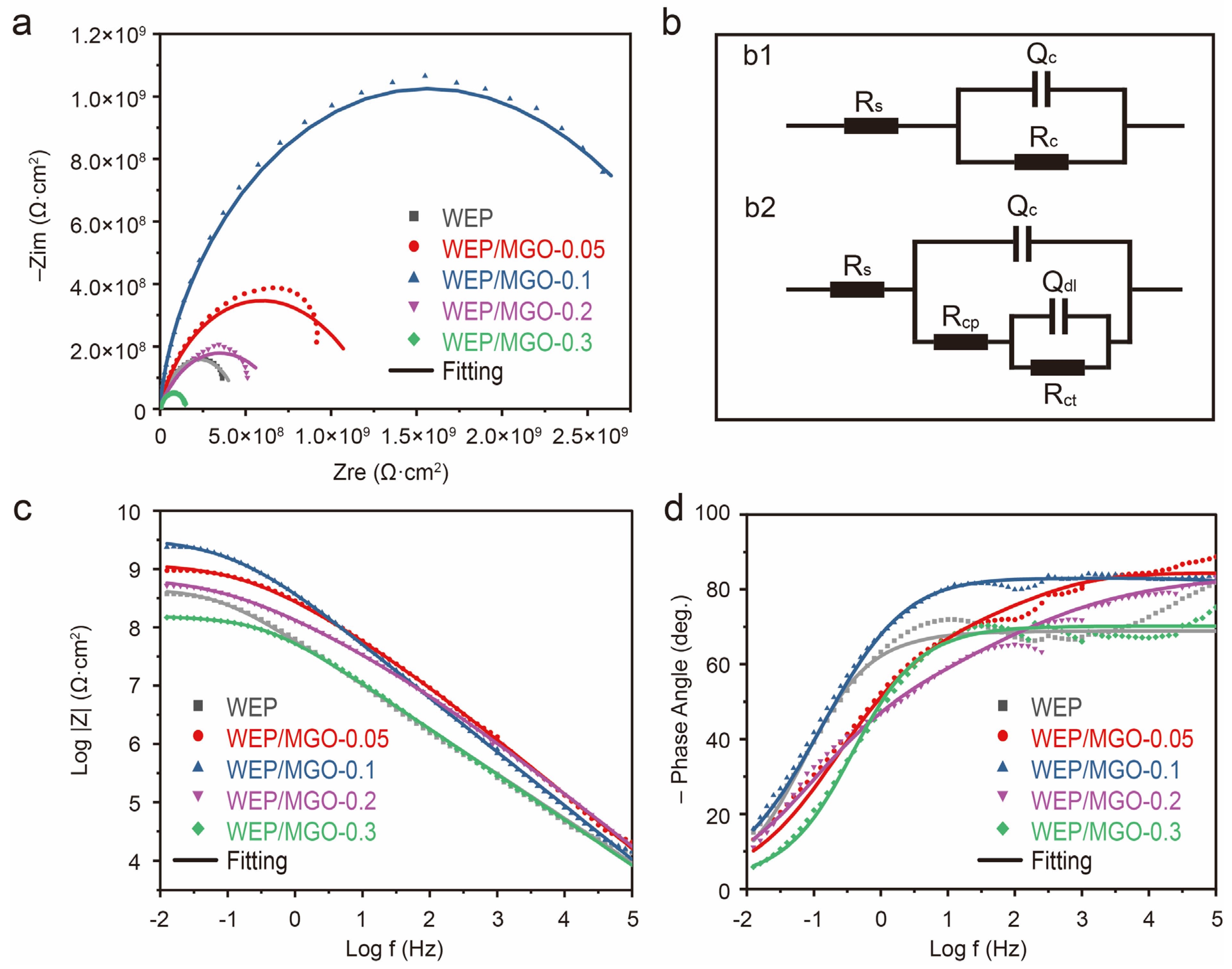
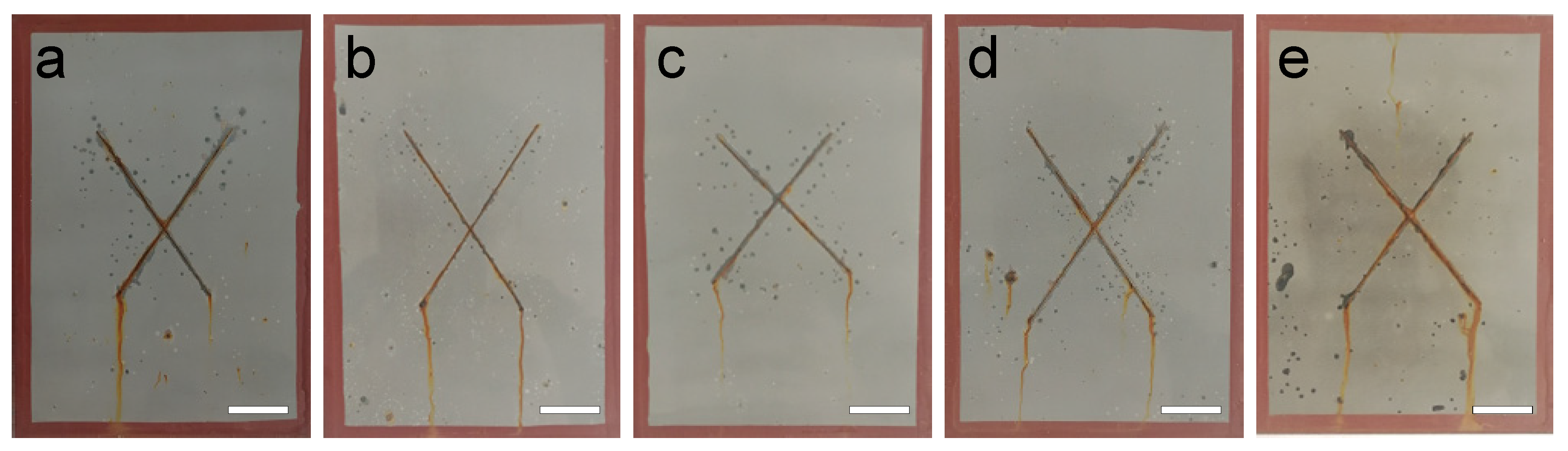
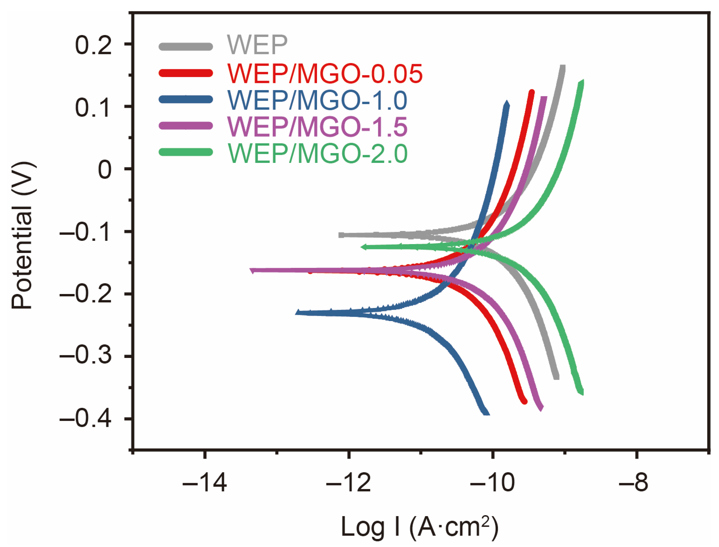
3.2. Corrosion Resistance of Epoxy Composite Coated Q235 Samples
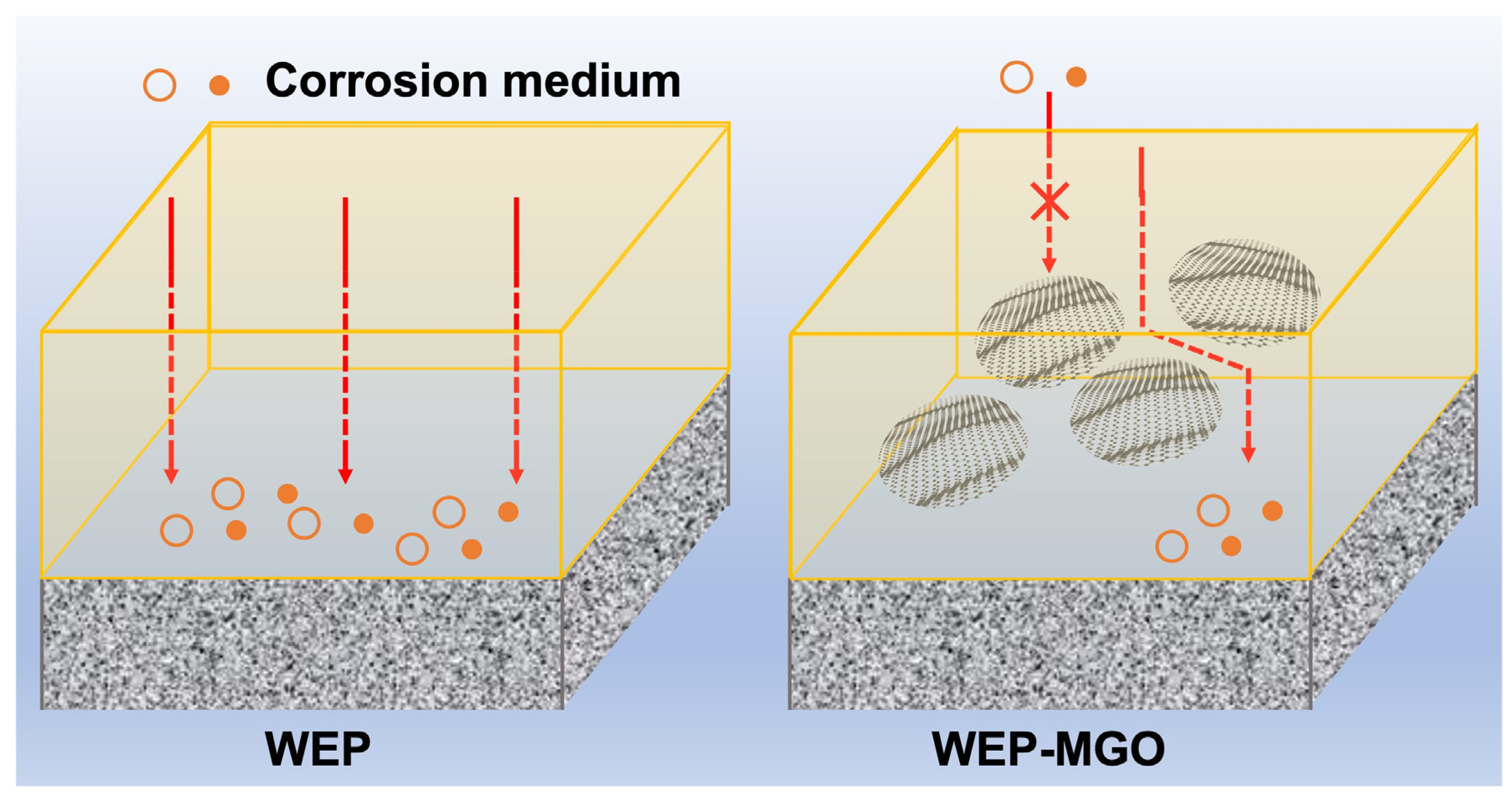
The electrochemical characteristics of pristine WEP and WEP/MGO composite coatings on Q235 samples were scrutinized using electrochemical impedance spectroscopy (EIS) and polarization testing leveraging a three-electrode system. The surface of the Q235 steel sample was enveloped in a protective layer and submerged in a corrosive electrolyte comprising a 3.5 wt.% NaCl solution for 48 h. Within the experimental setup, the saturated calomel electrode (SCE) served as the reference electrode, the platinum sheet acted as the auxiliary electrode, and the working electrode was a coated Q235 sample (coated with pure WEP or WEP/MGO). The EIS measurements were performed within a frequency range of 100 kHz to 10 mHz with a sinusoidal voltage with an amplitude of 20 mV applied at the open-circuit potential (OCP). During testing, a scan speed of 1 mV/s was utilized, ranging from negative to positive. All evaluations were conducted under room-temperature conditions (~20 °C) and exposed to ambient air. Subsequently, the impedance spectra were meticulously analyzed by employing ZSimpWin software v3.60. The experimental data were fitted to an electrical equivalent circuit, allowing for a comprehensive characterization and interpretation of the electrochemical behavior of the tested samples. MGO was incorporated at mass percentages of 0.05 wt.%, 0.1 wt.%, 0.15 wt.%, 0.2 wt.%, and 0.3 wt.%, leading to the designation of the corresponding epoxy coatings as WEP/MGO-0.05, WEP/MGO-0.1, WEP/MGO-0.15, WEP/MGO-0.2, and WEP/MGO-0.3, respectively.
The EIS plots, featuring Nyquist and Bode diagrams, for the pure WEP and WEP/MGO composite coating samples have been depicted in Figure 4. Figure 4a demonstrates Nyquist plots with a conspicuous variance in the semi-circle diameter between the pure WEP samples and the WEP/MGO coatings. The diameter of the impedance arc corresponds to the impedance value, and the larger diameter of the coated samples indicates that the coated samples possess improved corrosion resistance. After adding MGO, the diameter of the semi-circle of each coating sample is augmented to different extents. The impedance arc radius of WEP- and WEP/MGO-coated samples follows the following order: WEP/MGO-0.1 > WEP/MGO-0.05 > WEP/MGO-0.2 > WEP > WEP/MGO-0.3. Notably, when the addition ratio of MGO is 0.1%, the impedance arc radius is the most significant, indicating the highest level of corrosion resistance for the composite coating. However, excessive MGO leads to a decrease in the diameter of the semi-circle of WEP/MGO-0.3 due to the MGO agglomeration, which increases the defect. This suggests that the inclusion of MGO contributes to enhanced durability and protection against corrosion effects. And the corrosion resistance is optimal when the additional amount of MGO is 0.1 wt.%.
Moreover, different equivalent electrical circuits have been proposed to represent different failure stages within the WEP and WEP/MGO coating samples. Specifically, when corrosive media infiltrate the coating during the initial stages, the equivalent electrical circuit employed is identical to the one illustrated in Figure 4(b1). The coating resistance (Rc) exhibits a consistent decline over time as the corrosion process continues, thus serving as a reliable indicator of the overall protective performance of coatings. As the corrosion damage sustained by the coating intensifies, an increasing amount of corrosive media infiltrates the interface between the metal substrate and coatings, leading to the onset of corrosion on the substrate surface. At this stage, the equivalent electrical circuit employed is depicted in Figure 4(b2). As illustrated in Figure 4b, Rs represents solution resistance, Rc represents coating resistance, Rcp represents coating pore resistance, Rct represents charge transfer resistance, Qc represents CPE parameters of the EIS spectra of the coated specimens, and Qdl represents CPE parameters of the EIS spectra of the substrates. The corresponding fitting results are provided in Table 1.
In the Bode diagram, the impedance modulus at the lowest frequency (|Z|0.01Hz) is indicative of the coating’s corrosion resistance (Figure 4c,d). A higher impedance modulus at this frequency signifies a more effective anti-corrosion performance of the coating. Referring to Figure 4c, the |Z|0.01Hz of WEP and WEP/MGO coating samples follows the following order: WEP/MGO-0.1 > WEP/MGO-0.05 > WEP/MGO-0.2 > WEP > WEP/MGO-0.3. After being immersed in 3.5% NaCl for 48 h, the |Z|0.01Hz value of WEP was measured to be 3.77 × 10⁸ Ω·cm2. In contrast, the |Z|0.01Hz value of WEP/MGO-0.05 is significantly improved. When the additional amount of MGO reached 0.1 wt.%, it was observed that WEP/MGO-0.1 exhibited the highest |Z|0.01Hz value (2.85 × 10⁹ Ω·cm2). However, as the addition of MGO further increased to 0.2 wt.% and 0.3 wt.%, it was observed that the |Z|0.01Hz value of WEP/MGO-0.2 and WEP/MGO-0.3 decreased to 5.21 × 10⁸ Ω·cm2 and 1.47 × 10⁸ Ω·cm2, respectively. This phenomenon occurs because, when the filler content is low, MGO can be well dispersed in the coating, forming a dense physical barrier layer. This effectively prevents the infiltration of corrosive media, thereby significantly enhancing the corrosion resistance of the composite coating. As the addition of MGO incorporated into the coating is augmented, excess MGO congregates in the coatings, engendering a rise in the incidence of minuscule pores and imperfections within the coating. Consequently, these microstructural irregularities amplify the vulnerability of the corrosive medium to infiltrate the underlying metal substrate, culminating in a deterioration of the coating’s corrosion resistance. These results provide evidence that the addition of MGO effectively improves the corrosion resistance of WEP-coated samples. It further confirms that when the MGO mass fraction is 0.1 wt.%, WEP/MGO-0.1 displays optimal corrosion resistance.
Tafel polarization curves and fitting results of WEP and WEP/MGO coating samples were summarized and presented in Figure 5 and Table 2. The corrosion rate (CR) was calculated using the following formula:
C R = K · M · I c o r r ρ m
where K is a constant (3268.6 mol/A), M is the molecular weight (56 g/mol), and ρm is the density (7.85 g/cm3). It is observed that both the Icorr and CR showed a U-shaped relationship with the addition of MGO. This indicates that the presence of appropriate MGO contributes to a reduction in the severity of corrosion. When the addition of MGO is 0.1 wt.%, the Icorr (4.59 × 10⁻¹² A·cm−2) and CR (2.11 × 10⁻⁶ mpy) values of the WEP/MGO composite coating samples are the lowest. Overall, these results suggest that the WEP/MGO composite coating samples provide excellent protection against corrosion. However, the Icorr of WEP/MGO-0.3 during the electrochemical corrosion process is found to be the highest among coated Q235 samples. This suggests that the WEP/MGO-0.3-coated Q235 samples experienced the most severe corrosion.
To scrutinize the corrosion resistance of the WEP- and WEP/MGO-coated Q235 samples, an artificial scratch was carried out, followed by a salt spray evaluation. These samples were exposed to a controlled salt fog environment for a duration of 300 h. As depicted in Figure 6, localized corrosion spots were observed in proximity to the scratches. As the MGO content increased, the corrosion of the coating exhibited a gradual reduction. As depicted in Figure 6c, the WEP/MGO-0.01 composite coating exhibits an optimal level of corrosion resistance among the tested samples. Conversely, the corrosion of the WEP/MGO-0.03 coating sample intensified in Figure 6e. This can be attributed to the excessive MGO addition, resulting in an increased presence of pores and defects in the coating, thereby accelerating the diffusion of the corrosive medium to the substrate. The outcomes of the salt spray test demonstrate that the incorporation of MGO enhances the corrosion resistance of the coating.
During coating corrosion, inadequate adhesion of the coating facilitates the formation of electrochemical corrosion conditions, leading to gradual delamination of the coating as the corrosion reaction progresses, ultimately culminating in coating failure. Consequently, the adhesion of the coating plays a pivotal role in its resistance to aging and corrosion. The adhesion properties of WEP- and WEP/MGO-coated samples were assessed using a pull-off adhesion tester, measuring dry adhesion and wet adhesion (after immersion in a 3.5% NaCl aqueous solution for 7 days). The drawing speed was set at 0.5 MPa/s. The adhesion tests were conducted at five randomly selected positions above and below the coating (Figure S5). As depicted in Figure 7, the results exhibit the dry and wet adhesion characteristics of different coatings. It is evident that the addition of MGO significantly enhances both dry and wet adhesion properties compared to WEP coatings. The dry and wet adhesions of WEP were 1.78 MPa and 0.83 MPa, respectively. A decrease in adhesion and a high loss ratio indicate the reduced effectiveness of WEP in preventing the penetration of corrosive agents. However, the dry and wet adhesion of WEP/MGO increased, which remained at a high level. When the amount of MGO added was 0.2 wt.%, the wet adhesion of the WEP/MGO-0.2 sample was measured to be 2.34 MPa, representing a reduction of only 31%. The decreased adhesion loss rate suggests that the WEP/MGO coatings exhibited enhanced resistance to corrosion in a wet environment. Excessive MGO may not be uniformly dispersed within the WEP coatings, resulting in severe filler agglomeration. This uneven distribution and agglomeration of MGO can lead to a decrease in the adhesion of the WEP/MGO-0.3-coated sample and an increase in the loss ratio. Thus, the inclusion of 0.2 wt.% MGO exhibits commendable adhesion to the substrate and demonstrates exceptional performance.

3.3. Discussion

In order to achieve superior corrosion resistance in the coatings, it is critical to ensure proper dispersion of GO within the coating matrix. In this study, melamine was used for the chemical functionalization of GO, which resulted in strong covalent bonding between GO and the WEP coating. This approach allowed for exceptional dispersion properties of GO within the coating matrix, ultimately contributing to improved corrosion resistance. The covalent bonds between the amino group of melamine and the carboxyl groups and epoxide groups of the GO coating were formed through the reaction, as confirmed through FT-IR analyses. The observation of a new characteristic peak corresponding to C–N stretching vibration in the spectrum of MGO is noteworthy, as it confirms the successful formation of covalent bonds between GO and the melamine. Our research exhibits the triumphant dispersion of MGO, aided by a resilient sheet structure, uniformly throughout the WEP coating matrix. The integration of MGO has proven to be a highly effective measure for providing formidable protection against corrosive agents. For the pure WEP coating, the corrosive medium is easier to reach the substrate surface. For the WEP-MGO coating, the large layer of MGO is dispersed in the coating, which effectively hinders the penetration of corrosive media such as water and chloride ions and prolongs or blocks the corrosion path (Figure 8). As a result, the inclusion of MGO substantially augments the corrosion resistance of the coated samples. However, it is essential to acknowledge that an excessive quantity of MGO may cause pronounced agglomeration within the WEP coating matrix, consequently establishing localized pathways for corrosion. Hence, the integrity of the corrosion resistance in the coated samples may be compromised. Therefore, it is of utmost importance to optimize the content of MGO, striking a delicate equilibrium between enhanced corrosion resistance and the prevention of agglomeration-induced effects.

4. Conclusions

In summary, melamine-modified graphene oxide (MGO) was synthesized through surface covalent functionalization. Moreover, the optimal modifier addition ratio for modification was investigated. It was ascertained that the most favorable modification effect of melamine was achieved when the optimal mass ratio of GO to melamine was maintained at 5:1. The results showed that when the mass ratio of GO dispersion to melamine aqueous solution was 5:1, there was no melamine diffraction peak, and the interlayer spacing of MGO was 0.11 nm. And the maximum ID/IG value of MGO was 3.70, indicating that the modification process increased the disorder of the overall structure. Furthermore, the laminated MGO surface exhibits irregular, wrinkle-like structures, imparting exceptional barrier and shielding properties. The synthesis approach employed in this work has enabled the preparation of WEP-MGO coatings, which display exceptional corrosion resistance on the surface of Q235 steel, surpassing that of traditional anticorrosive coatings. EIS tests revealed a remarkable enhancement in the |Z|0.01Hz value for the WEP coating upon the incorporation of 0.1 wt.% of MGO, which is increased from 3.77 × 10⁸ Ω·cm2 of WEP to 2.85 × 10⁹ Ω·cm2 after immersion in 3.5% NaCl for 48 h. Furthermore, the corrosion expansion at both the scratch and corrosion spot frequencies of the samples displayed a remarkable attenuation following exposure to a 300-h salt spray test. In conclusion, the integration of MGO has resulted in substantial advancements in the corrosion resistance of WEP coatings. By exploring the structure-activity relationship of two-dimensional lamellar structural materials, this work highlights the potential of utilizing modified GO to enhance the corrosion resistance of WEP. It is conceivable that the key to future advancements in waterborne anticorrosive coatings lies in novel high-efficiency fillers.

Supplementary Materials

The following supporting information can be downloaded at: https://www.mdpi.com/article/10.3390/coatings14040488/s1. Figure S1: FT-IR spectra of GO and MGO; Figure S2: FT-IR spectra of GO and MGO (5:1), and local magnified views; Figure S3: Raman spectra of GO and MGO; Figure S4: XRD spectra of GO and MGO; Figure S5: Photograph of coating adhesion test.

Author Contributions

X.L.: conceptualization, formal analysis, writing—original draft preparation. D.L.: data curation. J.C.: writing—original draft preparation. D.H.: writing—original draft preparation. X.G.: formal analysis. J.D.: validation and editing. Y.Y.: validation and editing. J.L.: supervision, writing—reviewing and editing. D.N.: supervision, writing—reviewing and editing, funding acquisition. All authors have read and agreed to the published version of the manuscript.

Funding

The financial supports for this work are the Inner Mongolia Major Science and Technology Project (No. 2020ZD0024), the Local Science and Technology Development Project of the Central Government (No. 2021ZY0006 and No. 2022ZY0011), the Project of Innovation Research in Postgraduate in Inner Mongolia (No. B20231023Z), and the Inner Mongolia Autonomous Region Key Research and Technological Achievements Transformation Plan Project (No. 2023YFHH0063).

Institutional Review Board Statement

Not applicable.

Informed Consent Statement

Not applicable.

Data Availability Statement

Data are contained within the article.

Conflicts of Interest

The authors declare no conflict of interest.

References

  1. Ding, J.; Zhao, H.; Shao, Z.; Yu, H. Bioinspired Smart Anticorrosive Coatings with an Emergency-Response Closing Function. ACS Appl. Mater. Interfaces 2019, 11, 42646–42653. [Google Scholar] [CrossRef] [PubMed]
  2. Quezada-Rentería, J.A.; Cházaro-Ruiz, L.F.; Rangel-Mendez, J.R. Synthesis of reduced graphene oxide (rGO) films onto carbon steel by cathodic electrophoretic deposition: Anticorrosive coating. Carbon 2017, 122, 266–275. [Google Scholar] [CrossRef]
  3. Yimyai, T.; Crespy, D.; Rohwerder, M. Corrosion-Responsive Self-Healing Coatings. Adv. Mater. 2023, 35, e2300101. [Google Scholar] [CrossRef] [PubMed]
  4. Bender, R.; Féron, D.; Mills, D.; Ritter, S.; Bäßler, R.; Bettge, D.; De Graeve, I.; Dugstad, A.; Grassini, S.; Hack, T.; et al. Corrosion challenges towards a sustainable society. Mater. Corros. 2022, 73, 1730–1751. [Google Scholar] [CrossRef]
  5. Liu, T.; Ma, L.; Wang, X.; Wang, J.; Qian, H.; Zhang, D.; Li, X. Self-healing corrosion protective coatings based on micro/nanocarriers: A review. Corros. Commun. 2021, 1, 18–25. [Google Scholar] [CrossRef]
  6. Pletincx, S.; Fockaert, L.L.I.; Mol, J.M.C.; Hauffman, T.; Terryn, H. Probing the formation and degradation of chemical interactions from model molecule/metal oxide to buried polymer/metal oxide interfaces. NPJ Mater. Degrad. 2019, 3, 23. [Google Scholar] [CrossRef]
  7. Zheludkevich, M.; Tedim, J.; Ferreira, M. “Smart” coatings for active corrosion protection based on multi-functional micro and nanocontainers. Electrochim. Acta 2012, 82, 314–323. [Google Scholar] [CrossRef]
  8. Pei, L.; Lin, D.; Yuan, S.; Lu, R.; Bai, Z.; Sun, Y.; Zhu, Y.; Jiang, Y.; Zhu, J.; Wang, H. A multifunctional and long-term waterborne anti-corrosion coating with excellent ‘hexagonal warrior’ properties. Chem. Eng. J. 2023, 457, 141158. [Google Scholar] [CrossRef]
  9. Wang, X.; Li, C.; Zhang, M.; Lin, D.; Yuan, S.; Xu, F.; Zhou, Y.; Wang, C.; Zhu, Y.; Wang, H. A novel waterborne epoxy coating with anti-corrosion performance under harsh oxygen environment. Chem. Eng. J. 2022, 430, 133156. [Google Scholar] [CrossRef]
  10. Ghosal, A.; Iqbal, S.; Ahmad, S. NiO nanofiller dispersed hybrid Soy epoxy anticorrosive coatings. Prog. Org. Coat. 2019, 133, 61–76. [Google Scholar] [CrossRef]
  11. Quites, D.; Somers, A.; Forsyth, M.; Paulis, M. Development of waterborne anticorrosive coatings by the incorporation of coumarate based corrosion inhibitors and phosphate functionalization. Prog. Org. Coat. 2023, 183, 107781. [Google Scholar] [CrossRef]
  12. Feng, Z.; Song, G.-L.; Xu, Y.; Zheng, D.; Chen, X. Micro-galvanic corrosion during formation of epoxy coating. Prog. Org. Coat. 2020, 147, 105799. [Google Scholar] [CrossRef]
  13. Dong, Y.; Zhou, Q. Relationship between ion transport and the failure behavior of epoxy resin coatings. Corros. Sci. 2014, 78, 22–28. [Google Scholar] [CrossRef]
  14. Yin, Y.; Zhao, H.; Prabhakar, M.; Rohwerder, M. Organic composite coatings containing mesoporous silica particles: Degradation of the SiO2 leading to self-healing of the delaminated interface. Corros. Sci. 2022, 200, 110252. [Google Scholar] [CrossRef]
  15. Yin, Y.; Schulz, M.; Rohwerder, M. Optimizing smart self-healing coatings: Investigating the transport of active agents from the coating towards the defect. Corros. Sci. 2021, 190, 109661. [Google Scholar] [CrossRef]
  16. Enríquez, E.; Fernández, J.; de la Rubia, M. Highly conductive coatings of carbon black/silica composites obtained by a sol–gel process. Carbon 2012, 50, 4409–4417. [Google Scholar] [CrossRef]
  17. Zahidah, K.A.; Kakooei, S.; Ismail, M.C.; Raja, P.B. Halloysite nanotubes as nanocontainer for smart coating application: A review. Prog. Org. Coat. 2017, 111, 175–185. [Google Scholar] [CrossRef]
  18. Lamprakou, Z.; Bi, H.; Weinell, C.E.; Tortajada, S.; Dam-Johansen, K. Smart epoxy coating with mesoporous silica nanoparticles loaded with calcium phosphate for corrosion protection. Prog. Org. Coat. 2022, 165, 106740. [Google Scholar] [CrossRef]
  19. Chen, Z.; Yang, W.; Yin, X.; Chen, Y.; Liu, Y.; Xu, B. Corrosion protection of 304 stainless steel from a smart conducting polypyrrole coating doped with pH-sensitive molybdate-loaded TiO2 nanocontainers. Prog. Org. Coat. 2020, 146, 105750. [Google Scholar] [CrossRef]
  20. Ma, X.; Xu, L.; Wang, W.; Lin, Z.; Li, X. Synthesis and characterisation of composite nanoparticles of mesoporous silica loaded with inhibitor for corrosion protection of Cu-Zn alloy. Corros. Sci. 2017, 120, 139–147. [Google Scholar] [CrossRef]
  21. Dreyer, D.R.; Park, S.; Bielawski, C.W.; Ruoff, R.S. The chemistry of graphene oxide. Chem. Soc. Rev. 2010, 39, 228–240. [Google Scholar] [CrossRef] [PubMed]
  22. Zhang, H.; Han, J.; Yang, B. Structural Fabrication and Functional Modulation of Nanoparticle–Polymer Composites. Adv. Funct. Mater. 2010, 20, 1533–1550. [Google Scholar] [CrossRef]
  23. Ma, Y.; Huang, H.; Zhou, H.; Graham, M.; Smith, J.; Sheng, X.; Chen, Y.; Zhang, L.; Zhang, X.; Shchukina, E.; et al. Superior anti-corrosion and self-healing bi-functional polymer composite coatings with polydopamine modified mesoporous silica/graphene oxide. J. Mater. Sci. Technol. 2021, 95, 95–104. [Google Scholar] [CrossRef]
  24. Ramezanzadeh, B.; Ghasemi, E.; Mahdavian, M.; Changizi, E.; Moghadam, M.M. Covalently-grafted graphene oxide nanosheets to improve barrier and corrosion protection properties of polyurethane coatings. Carbon 2015, 93, 555–573. [Google Scholar] [CrossRef]
  25. Ning, Y.-J.; Zhu, Z.-R.; Cao, W.-W.; Wu, L.; Jing, L.-C.; Wang, T.; Yuan, X.-T.; Teng, L.-H.; Bin, P.-S.; Geng, H.-Z. Anti-corrosion reinforcement of waterborne polyurethane coating with polymerized graphene oxide by the one-pot method. J. Mater. Sci. 2021, 56, 337–350. [Google Scholar] [CrossRef]
  26. Ramezanzadeh, B.; Bahlakeh, G.; Ramezanzadeh, M. Polyaniline-cerium oxide (PAni-CeO2) coated graphene oxide for enhancement of epoxy coating corrosion protection performance on mild steel. Corros. Sci. 2018, 137, 111–126. [Google Scholar] [CrossRef]
  27. Qi, K.; Sun, Y.; Duan, H.; Guo, X. A corrosion-protective coating based on a solution-processable polymer-grafted graphene oxide nanocomposite. Corros. Sci. 2015, 98, 500–506. [Google Scholar] [CrossRef]
  28. Ramezanzadeh, B.; Niroumandrad, S.; Ahmadi, A.; Mahdavian, M.; Moghadam, M.M. Enhancement of barrier and corrosion protection performance of an epoxy coating through wet transfer of amino functionalized graphene oxide. Corros. Sci. 2016, 103, 283–304. [Google Scholar] [CrossRef]
  29. Kuilla, T.; Bhadra, S.; Yao, D.; Kim, N.H.; Bose, S.; Lee, J.H. Recent advances in graphene based polymer composites. Prog. Polym. Sci. 2010, 35, 1350–1375. [Google Scholar] [CrossRef]
  30. Li, F.; Ma, Y.; Chen, L.; Li, H.; Zhou, H.; Chen, J. In-situ polymerization of polyurethane/aniline oligomer functionalized graphene oxide composite coatings with enhanced mechanical, tribological and corrosion protection properties. Chem. Eng. J. 2021, 425, 130006. [Google Scholar] [CrossRef]
  31. Wu, Y.; He, Y.; Chen, C.; Zhong, F.; Li, H.; Chen, J.; Zhou, T. Non-covalently functionalized boron nitride by graphene oxide for anticorrosive reinforcement of water-borne epoxy coating. Colloids Surf. A Physicochem. Eng. Asp. 2020, 587, 124337. [Google Scholar] [CrossRef]
  32. Tian, Y.; Wang, W.; Zhong, L.; Jiang, X.; Zhang, X. Investigation of the anticorrosion properties of graphene oxide-modified waterborne epoxy coatings for AA6061. Prog. Org. Coat. 2022, 163, 106655. [Google Scholar] [CrossRef]
  33. Chai, Z.-L.; Chen, Y.-X.; Zhou, D.; Zhang, M.; Liu, J.-K. Excellent corrosion resistance of FGO/Zn2SiO4 composite material in epoxy coatings. Prog. Org. Coat. 2022, 170, 106992. [Google Scholar] [CrossRef]
  34. Wan, Y.-J.; Tang, L.-C.; Gong, L.-X.; Yan, D.; Li, Y.-B.; Wu, L.-B.; Jiang, J.-X.; Lai, G.-Q. Grafting of epoxy chains onto graphene oxide for epoxy composites with improved mechanical and thermal properties. Carbon 2014, 69, 467–480. [Google Scholar] [CrossRef]
  35. Pourhashem, S.; Vaezi, M.R.; Rashidi, A.; Bagherzadeh, M.R. Exploring corrosion protection properties of solvent based epoxy-graphene oxide nanocomposite coatings on mild steel. Corros. Sci. 2017, 115, 78–92. [Google Scholar] [CrossRef]
Figure 1. Schematic diagram of the preparation process for MGO and WEP/MGO coatings.
Coatings 14 00488 g001
Figure 2. FT-IR spectra (a), Raman spectra (b), and XRD spectra (c) of GO and MGO.
Coatings 14 00488 g002
Figure 3. SEM images of GO (a) and MGO (b). TEM images of GO (c) and MGO (d).
Coatings 14 00488 g003
Figure 4. Nyquist plots (a), equivalent electrical circuits (b), and Bode diagrams (c,d) of WEP and WEP/MGO coating samples (immersion in 3.5% NaCl for 48 h).
Coatings 14 00488 g004
Figure 5. Tafel polarization curves of WEP and WEP/MGO coatings immersed in a 3.5% NaCl solution for 48 h.
Coatings 14 00488 g005
Figure 6. Images of WEP and WEP/MGO coating samples after a salt spray test for 300 h (scale bar: 1 cm). (a) WEP, (b) WEP/MGO-0.05, (c) WEP/MGO-0.1, (d) WEP/MGO-0.2, and (e) WEP/MGO-0.3.
Coatings 14 00488 g006
Figure 7. Pull-off adhesion results of coated Q235 steel substrates.
Coatings 14 00488 g007
Figure 8. Schematic diagram of the mechanism of corrosion resistance of coated samples.
Coatings 14 00488 g008
Table 1. Electrochemical parameters obtained from the EIS for the coated Q235 steel samples (immersion in 3.5% NaCl for 48 h).
WEPWEP/MGO-0.05WEP/MGO-0.1WEP/MGO-0.2WEP/MGO-0.3
Rs (ohm·cm2)9.52 × 10−41.53 × 1029.99 × 10−31.00 × 10−46.14 × 10−4
Qc-Y0−1·cm−2·sn)4.10 × 10−94.27 × 10−102.14 × 10−105.15 × 10−103.71 × 10⁻⁹
Qc-n7.61 × 10−19.22 × 10−19.33 × 10−18.56 × 10−17.77 × 10−1
Rcp (ohm·cm2)4.61 × 1088.41 × 1087.20 × 1049.34 × 1081.50 × 108
Qdl-Y0−1·cm−2·sn)3.92 × 10−115.96 × 10−102.03 × 10−92.16 × 10−73.06 × 10⁻⁷
Qdl-n5.92 × 10−15.23 × 10−15.57 × 10−18.72 × 10−13.83 × 10−1
Rct (ohm·cm2)5.332.69 × 1097.26 × 1083.761.30 × 102
Table 2. Electrochemical parameters obtained from polarization curves for the Q235 steel coated with WEP and WEP/MGO.
SamplesIcorr (A/cm2)CR (mm/Year)
WEP3.76 × 10−111.73 × 10⁻⁵
WEP/MGO-0.051.55 × 10−117.13 × 10⁻⁶
WEP/MGO-0.14.59 × 10−122.11 × 10⁻⁶
WEP/MGO-0.21.89 × 10−118.57 × 10⁻⁶
WEP/MGO-0.37.42 × 10−113.41 × 10⁻⁵
Disclaimer/Publisher’s Note: The statements, opinions and data contained in all publications are solely those of the individual author(s) and contributor(s) and not of MDPI and/or the editor(s). MDPI and/or the editor(s) disclaim responsibility for any injury to people or property resulting from any ideas, methods, instructions or products referred to in the content.

