Article

Design and Performance Study of Carbon Fiber-Reinforced Polymer Connection Structures with Surface Treatment on Aluminum Alloy (6061)

1
State Key Laboratory for Modification of Chemical Fibers and Polymer Materials, College of Materials Science and Engineering, Donghua University, Shanghai 201620, China
2
Center for Civil Aviation Composites, Donghua University, Shanghai 201620, China
3
Shanghai Key Laboratory of Lightweight Structural Composites, Donghua University, Shanghai 201620, China
*
Author to whom correspondence should be addressed.
Coatings 2024, 14(7), 785; https://doi.org/10.3390/coatings14070785
Submission received: 30 May 2024 / Revised: 14 June 2024 / Accepted: 19 June 2024 / Published: 23 June 2024

Abstract

:
The existing connection methods for aluminum alloy profiles primarily include adhesive bonding and mechanical connections, with metal welding being widely employed. However, metal welding connections exhibit issues such as low joint strength, significant welding deformation, susceptibility to surface oxidation, poor welding surface quality, and challenges in achieving thin-walled metal structures. This paper presents a novel aluminum alloy connection structure that utilizes carbon fiber-reinforced polymer (CFRP) composites to replace welding for connecting aluminum alloy profiles. This innovative aluminum alloy composite connection structure not only enhances connection strength but also addresses the difficulties associated with metal welding. Research indicates that the optimal width of the CFRP structure in the connector is 60 mm, and with synergistic treatment of the aluminum alloy surface, the connection enhancement effect is optimal. Under these conditions, the tensile load can reach 58.71 kN and the bending load can reach 14.33 kN, which are 375.38% and 380.87% higher than those of welded aluminum alloy connections, respectively. The mass-specific strength increases by 106.27% and 134.42%, respectively. Simulations of this connection structure in components demonstrate that it improves strength by 73.99% and mass-specific strength by 71.95% compared to pure metal welded connections. Using ABAQUS 2023 software for simulation and calculation, the difference between the simulation and experimental results is within 5%, verifying the feasibility of the designed structure. This study provides new insights and a theoretical foundation for the development and application of hybrid connection methods involving metal and fiber-reinforced composites.

1. Introduction

With the rapid development of economic globalization and industrialization, global energy consumption has surged. To save energy and reduce emissions, the automotive industry is advancing the development of lightweight vehicles. This initiative aims to reduce energy consumption both during vehicle use and in the manufacturing process. As new materials, structures, and manufacturing processes continue to evolve, vehicle lightweighting has garnered increasing attention [1,2,3,4,5]. Basic materials for vehicle manufacturing, such as low-carbon steel and cast iron, are being replaced by materials with higher specific strength and stiffness, such as advanced high-strength steels, aluminum, magnesium, and polymer composites. The key challenge lies in reducing the cost of manufacturing structures with these new materials. To achieve maximum weight reduction, it is essential to optimize the design using various forms of multi-materials. This use of hybrid materials presents additional challenges in terms of connections [6,7,8,9,10].
Adhesive bonding and mechanical connections remain the most widely used methods for connecting CFRP (carbon fiber-reinforced polymer) to metals. These technologies enable effective bonding between metals and non-metallic materials like CFRP and are already in large-scale industrial production. However, each connection method has its own advantages and disadvantages [11,12].
In the mechanical connection technology for CFRP and aluminum alloys, common methods include riveting, bolting, and press-fit connections. Bolted connections are a maturing technology that does not require external heat, relying on friction between connected components to transfer stress [13]. When external forces exceed the friction limit, relative sliding occurs, causing the threads and hole walls to compress and generate shear forces. Research has identified failure modes in bolted connections under tensile load, such as tensile failure, pull-out failure, bearing failure, and shear failure [14]. The toughness of composite materials significantly impacts connection strength [15]. However, bolted connections have drawbacks, including increased weight and fiber interruption during drilling, which leads to stress concentrations and reduced tensile strength, compromising connection integrity [16]. Riveting offers easy installation and stable stress distribution, making it suitable for complex structures. Self-piercing riveting, a cold forming mechanical connection process, is widely used in the automotive and aerospace industries. It does not require pre-drilling; instead, a punch press applies pressure, causing plastic deformation to achieve the connection [17]. Wang [18] demonstrated through tensile shear tests that cured self-piercing rivet joints have superior strength compared to conventional joints, with Al/CFRP/Al joints reaching a maximum load of 2.22 kN. However, this method shares similar issues with bolted connections. Press-fit connections, frequently used in the automotive industry, are similar to mechanical clinching. This cold connection technique uses a punch to press the upper sheet through the hole in the lower sheet into the die cavity, creating a mechanical interlock through plastic deformation [19]. This method does not involve riveting or generate heat, facilitating automation. However, these methods are limited by the structural dimensions and shapes of the connectors, making them unsuitable for complex structures and relatively costly.
Adhesive bonding uses adhesives to join two materials into a unified structure, avoiding damage to the composite’s fiber structure, reducing stress concentration in mechanical connections, and adding minimal weight while providing an aesthetically pleasing surface [20]. Ramezani et al. [21] studied the effects of adding components to adhesives and varying metal layer thickness on the failure load and modes of bonded composite joints. Despite its advantages, adhesive bonding can suffer from brittle fracture and joint failure at low temperatures, high costs, and difficulties in controlling adhesive ratios and quantities, leading to poor bonding strength. Ni et al. [22] found that polyurethane adhesive joints show superior mechanical performance and durability compared to epoxy and acrylic adhesives in galvanized steel and SMC composite joints. Surface preparation significantly impacts bonding performance; treatments like phosphoric acid anodization and primer coating can notably enhance interfacial strength [23]. While adhesive bonding mitigates part deformation and uneven stress distribution, it has drawbacks such as susceptibility to brittle fracture at low temperatures, long curing times, high costs, and challenges in controlling adhesive application. Sun et al. [24] investigated the mechanical behavior and failure mechanisms of various joint methods for connecting CFRP laminate and aluminum alloy, including adhesive joints, rivet joints, and hybrid adhesive−rivet joints. They found that adhesive joint failure mainly occurred at the interface, rivet joint failure was due to stress concentration around pre-drilled holes, and hybrid joints showed an interactive reinforcing effect between rivets and the adhesive.
Welding is an effective method for connecting aluminum alloys, addressing issues like stress concentration from drilling and added weight from fasteners, as well as long curing times in the adhesive processes [25,26]. Metal welding can be categorized into gas welding, resistance welding, arc welding, solid-state welding, and advanced technologies such as laser and electron beam welding [27]. Arc welding, which converts electrical energy into heat to melt and cool the electrode and workpiece, is suitable for composite material joints but often results in large heat-affected zones and brittle alloy layers. Laser welding, popular for its automation potential, high efficiency, and non-contact nature, is divided into laser transmission joining (LTJ) and laser direct joining (LDJ) [27,28,29,30]. LTJ focuses energy to melt the interface resin, allowing it to diffuse into the metal, while LDJ conducts heat through the metal to melt the resin and complete the bond. Aluminum alloy welding challenges include low joint strength, significant deformation, easy oxidation, poor surface quality, and inconsistent weld quality. Researchers have enhanced welding strength by incorporating other materials into aluminum alloys. Suresh [31] studied SiC nanoparticle-reinforced friction stir spot-welded 6061-T6 aluminum alloy, finding that SiC nanoparticles significantly influenced grain size and welding performance. The stir zone showed a maximum hardness of 93 HV and a maximum shear load of 2650.5 N with 29% SiC content. Sonoya [32] examined the relationship between spot welding conditions and the properties of the 6061 aluminum alloy, focusing on joint strength and fracture modes. The study revealed that a high welding current and low resistance make aluminum alloy spot welding challenging, with microcrack formation being a major factor in reducing the maximum tensile load of the weld.
Co-curing refers to the process of simultaneously curing uncured composite material layers and metal materials in a single curing cycle. The application of integral co-curing technology in joining techniques can significantly reduce the number of parts and lower the assembly costs of structural components. The temperature during co-curing promotes thorough resin penetration into the metal and maintains an optimal layer structure. The pressure and vacuum environment during co-curing help expel air from fiber−metal laminates, preventing future corrosion. Overall, the advantages of co-cured structures include fewer parts, reduced fasteners, fewer assembly issues, a single curing process, and better economic efficiency. However, the differing physical properties of heterogeneous materials can generate residual internal stresses during curing, impacting the performance of the composite material and the overall component. Prussak [33] et al. developed a real-time detection system that intelligently adjusts the heating and cooling rates during curing, reducing residual thermal stress by 77%. However, this method is complex and requires parameter adjustments based on material size. To address this, Zhu Wei [34] et al. simplified the detection apparatus, focusing on modifying curing parameters during heating to influence the generation of residual thermal stress.
A key factor influencing co-curing connections is the bonding effectiveness at the aluminum alloy and composite material interface. To enhance interface bonding strength, aluminum alloy surfaces are treated using physical or chemical methods. Physical treatments, such as sandblasting, laser etching, and grinding, increase surface roughness and remove impurities, corrosion, and contaminants. Park et al. [35] used various sandpapers to mechanically treat aluminum alloy surfaces, effectively removing the oxide layer, increasing surface roughness, and enhancing shear strength between metal and composites. Mu et al. [36] found that carbon fiber composite adhesion significantly improved after sandpaper grinding.
Boon et al. [37] studied two mechanical treatment processes, sandblasting and grooving, for different metal liners used in composite pipes. They found that, compared to sandblasting, grooving increased the contact area and improved the adhesion of the composite material. Chemical treatment can achieve surface modification without affecting the material itself, a feat that is difficult with traditional methods. Most chemical treatments involve immersing or coating materials with chemicals to alter surface properties or increase surface roughness [38]. Metal surface chemical treatments, such as acid etching and alkali washing, enhance the bonding performance between metal and resin composites by increasing surface roughness and polarity [39]. Plasma treatment uses high-voltage ionized gas to generate a jet of electrons and atoms, effectively treating material surfaces. During air ionization, a large number of active particles are ejected onto the material surface, causing cleaning, etching, surface activation, and cross-linking. This process creates high-energy polar groups on the material surface, which form new functional groups with introduced free radicals, significantly improving wettability and adhesion, increasing surface energy, and enhancing bonding strength [40]. Plasma treatment is simple, environmentally friendly, and efficient, making it widely used for adhesive surface pre-treatment. Bónová et al. [41] used 2.45 GHz of atmospheric microwave plasma to clean 7075-T6 aluminum alloy surfaces, demonstrating effective cleaning. Muñoz et al. [42] found that argon and argon−nitrogen microwave plasma treatments significantly increased hydrophilicity and surface energy. However, hydrophilicity and surface energy returned to baseline after 24–48 h due to free radical decay. Li et al. [43] showed that a plasma treatment distance of 10 mm and duration of 80 s yielded the best bonding strength, increasing it nearly fourfold.
To address issues such as low joint strength, significant welding deformation, oxidation, poor surface quality, and difficulties in welding thin components in aluminum alloys, this paper proposes a novel connection structure using surface-treated aluminum alloys and composite materials. The aluminum alloy surface undergoes plasma and laser treatment, while inner and outer composite prepregs are formed using thermal expansion foam and atmospheric pressure. This composite structure facilitates the connection of aluminum alloys. The study investigates the effect of different CFRP component widths on connection strength and examines the impact of aluminum alloy surface treatments on connection performance. Finite element analysis of the CFRP−aluminum alloy connection was performed using ABAQUS 2023 software. A simplified structural component for an electric vehicle battery case was designed to validate the applicability of this connection design. This research provides insights and a theoretical foundation for developing and applying other novel metal/composite hybrid structures.

2. Experiments

2.1. Experimental Materials

The main materials used in the experiment are shown in Table 1.

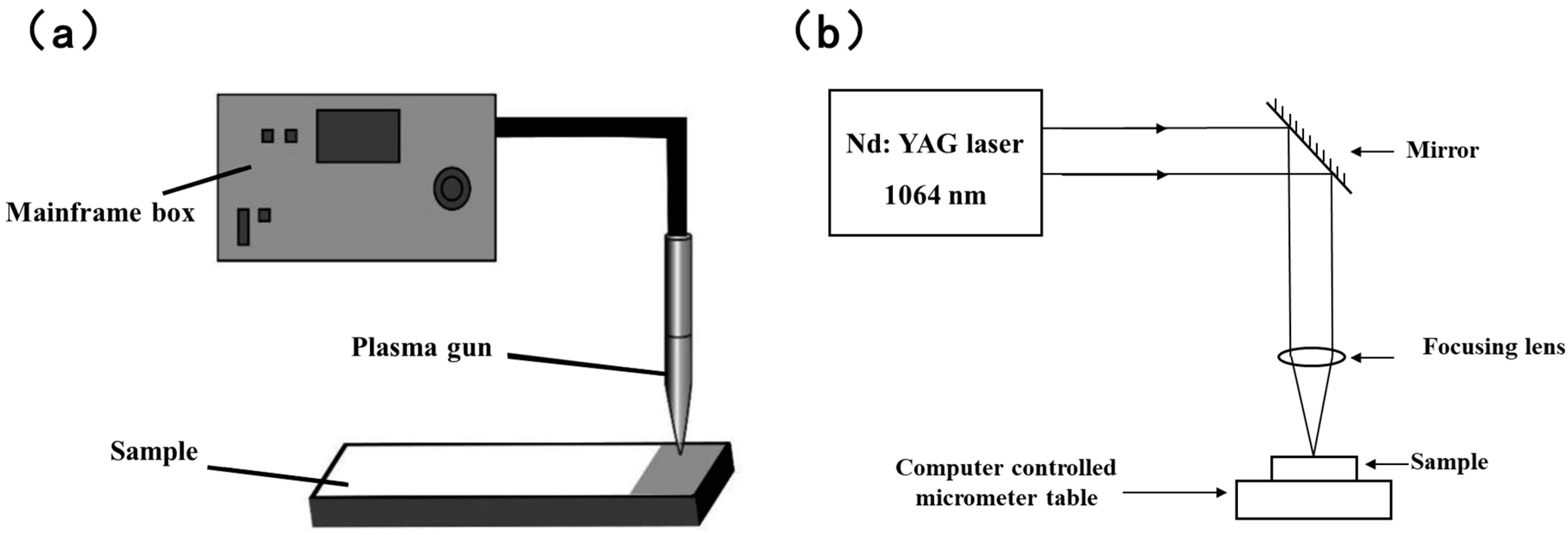
2.2. Experimental Equipment

The main experimental instruments used in the experiment, along with their names, models, and manufacturers, are shown in Table 2.

2.3. Experimental Methods

2.3.1. Aluminum Alloy Surface Treatment

This study utilized a combination of laser and plasma treatments for the surface processing of aluminum alloy samples. The schematic is shown in Figure 1, where Figure 1a illustrates the principle of atmospheric plasma surface treatment, and Figure 1b shows the laser surface treatment using a UV laser marking machine. Optimal surface treatment parameters were determined through prior research, and the selected parameters for the combined treatment are listed in Table 3.

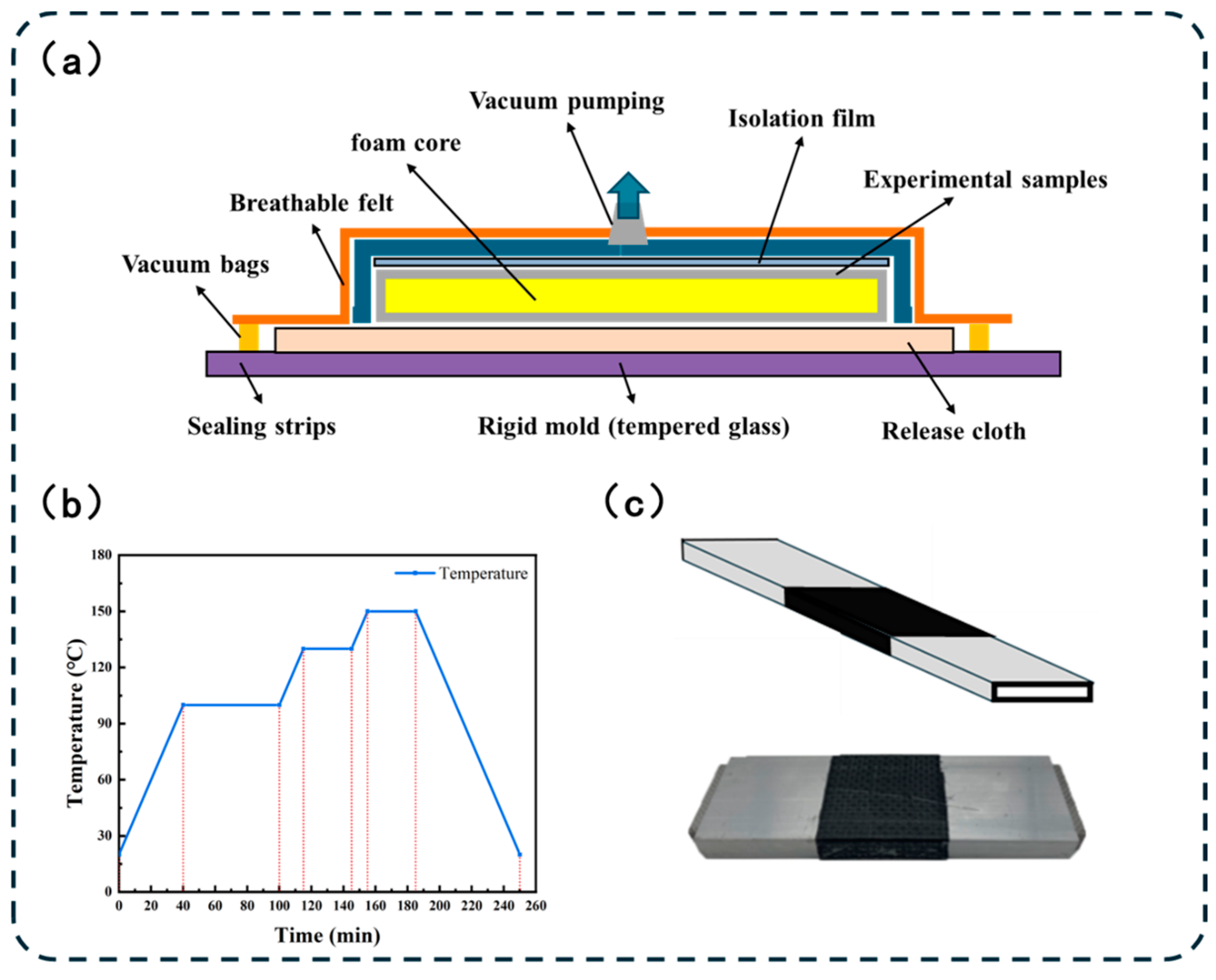
2.3.2. The Preparation of Composite Material Structure Connection Specimens

The process diagram for preparing composite material structure connection specimens is shown in Figure 2. The process is started by creating PET foam cores of different widths. Then, expandable foam is wrapped around the foam cores and a 1 mm prepreg layer is applied on the outer surface, as depicted in Figure 2a. The prepared CFRP cores of varying widths are placed inside the aluminum alloy, and two aluminum pieces are joined together, as shown in Figure 2b. Depending on the experimental conditions, surface treatment of the aluminum alloy may be performed. Finally, a 1 mm thick layer of CFRP prepreg of the corresponding width is wrapped around the aluminum alloy joint, as shown in Figure 2c.
During the vacuum bag molding process, carbon fiber prepreg is first applied to the aluminum alloy surface and then placed on tempered glass covered with release fabric. A release film separates the sample surface from the breather. A vacuum port is prepared, and a breather with good permeability that will not block the vacuum line is inserted, as shown in Figure 3a. Throughout curing, the vacuum pump maintains a continuous vacuum and internal pressure. The vacuum bag is placed in an oven for a three-stage curing process; the pressure is maintained above 0.96 bar. Initially, the temperature is increased from room temperature to the resin’s pre-curing temperature (100 °C) at 2 °C/min and held for 1 h to ensure uniform resin flow. Then, the heat is raised to 130 °C, and this temperature is maintained for 0.5 h. Finally, the temperature is increased to 150 °C and maintained for 0.5 h for post-curing. After complete curing, the sample is cooled to room temperature at 2 °C/min. The temperature control curve is illustrated in Figure 3b. Once cooled to room temperature, the pressure is released and the cured CFRP−aluminum alloy joint sample is extracted, as shown in Figure 3c.

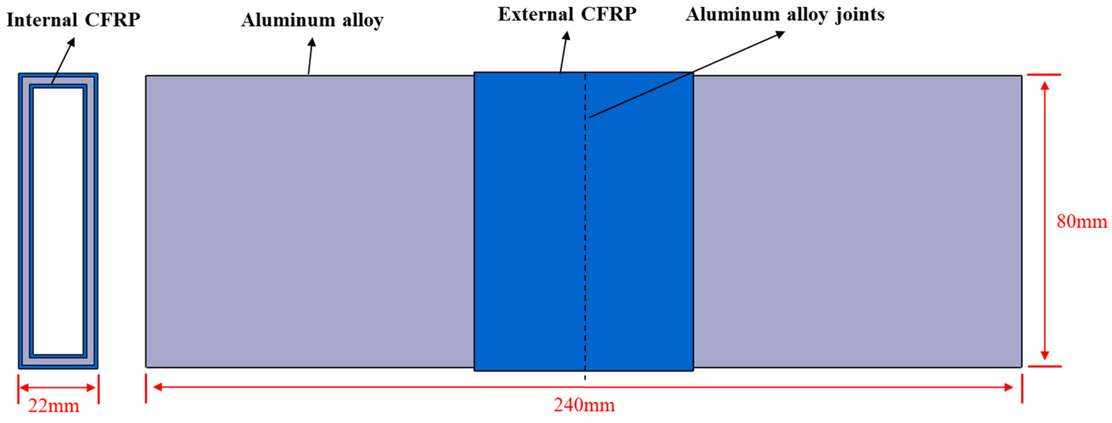
2.3.3. The Preparation of Structural Connection Component Casings

To simulate the application of aluminum alloy connections in product components, the structure of the lower battery box of a new energy vehicle was simplified to validate the enhancement of the aluminum alloy connection strength. This study utilizes a vacuum bag molding process in the CFRP−aluminum composite lower box structure where the prepreg is wrapped and pressurized using a vacuum bag and then cured at high temperatures to produce high-strength, high-toughness, and high-reliability composite materials. Additionally, the study examines the mechanical performance trends of box samples before and after aluminum alloy welding connections and surface treatments in CFRP foam-core sandwich structures.
The CFRP−aluminum composite lower box used in the experimental tests mainly consists of aluminum alloy profile side beams, PET solid-foam base plates, and carbon fiber plain-weave prepregs, as shown in Figure 4. The connection between aluminum alloy profiles primarily relies on the prepreg at the connection points, making the production process of CFRP connection enhancement components crucial. For the internal CFRP connection components within the aluminum alloy, L-shaped PET solid-foam is first cut as the support core, followed by wrapping with expanding foam and two layers of prepreg. Then, the connector is inserted into the corner joints of the aluminum alloy side beams, and the tackiness of the prepreg is used for the preliminary fixation of the components. The side beams are then placed on the foam base plate, with the entire exterior surface wrapped in three layers of prepreg (total thickness approximately 1.5 mm). The assembled product is vacuum bagged and vacuum bag molded. The temperature control process parameters used during molding are shown in Figure 3b. After curing, the oven is turned off, and the molded structural parts are removed from the oven and the vacuum bag, resulting in the final product structure.

2.4. Analysis and Testing Methods

2.4.1. Tensile Testing

The tensile test specimens for the connectors measure 240 mm × 80 mm × 22 mm, with an aluminum alloy thickness of 2 mm. The width of the external CFRP section is a variable. The specimen dimensions are shown in Figure 5. The aluminum alloy ends are clamped, and tensile tests are performed using a universal testing machine. Due to the non-standard dimensions, the tests follow the GB/T 228.1-2010 standard [44], with displacement control at a speed of 1 mm/min.

2.4.2. Bending Testing

The bending performance test of the connectors uses specimens of the same dimensions as those used for the tensile test. A universal testing machine is used to conduct a three-point bending test with a span of 200 mm based on the specimen dimensions. The bending test follows the GB/T 232-2010 standard [45], with displacement control at a speed of 2 mm/min. Both the loading and supporting rod diameters are 10 mm with a support span of 200 mm.

2.4.3. Compression Test

To investigate the performance improvement of the structure when applied to the lower case of an automotive battery box, we simulated the extrusion test required for the lower case of the battery box on the structure’s connectors. The box structure was placed on its side in the testing machine, with two metal plates placed above and below it to facilitate the movement of the machine’s beam. The loading speed of the machine’s beam was set to 2 mm/min.

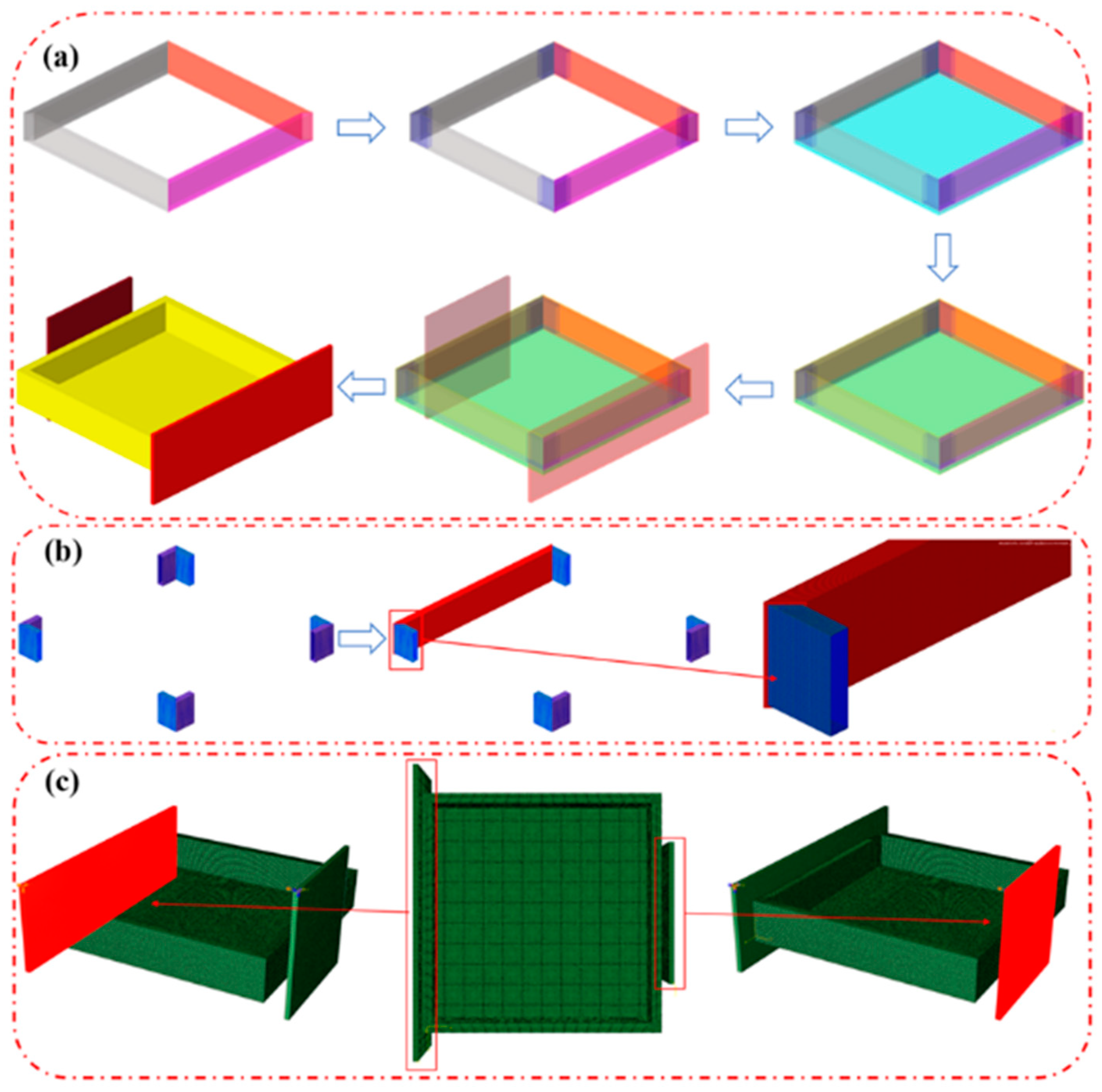
2.4.4. Finite Element Analysis

Finite element analysis (FEA) of the relevant tests was conducted using ABAQUS 2023 software. This analysis included defining the geometric dimensions of the structural model, specifying material property parameters, and setting the test conditions.

Geometric Dimensions of the Model

The connection structure specimens were designed with the same geometric dimensions as the test samples. The model consisted of two symmetrical aluminum alloy profiles, each measuring 120 mm in length, 80 mm in width, and 2 mm in thickness. The CFRP reinforcement components were divided into two parts: the inner and outer surfaces of the aluminum alloy profiles. Both the inner and outer CFRP layers had a thickness of 1 mm.

Material Properties

The aluminum alloy used was Al-6061 with a density of ρ = 2.70 g/cm3, an elastic modulus of E = 68.9 GPa, a Poisson’s ratio of ν = 0.33, and a shear modulus of 26.0 GPa. These material parameters were referenced from the conventional 6061 aluminum alloy properties in material databases. In the experiment, plain-weave prepreg was used with a single CFRP layer thickness set to 0.50 mm. The CFRP layers on the inner and outer surfaces of the aluminum alloy were defined with 0° and 90° cross-ply composite material parameters. The prepreg material parameters were obtained through testing of composite laminate specimens. Detailed material parameters were provided in Table 4.

Establishment of Interface Contact Modeling

To determine the critical points of the shear slip curve in the model, the relevant research literature [46,47] was consulted. It was found that strain gauges can be applied at the composite material interface connections to obtain force, displacement, and strain data during the interface performance test process. These data were then analyzed, and a numerical expression was used to calculate the slip trend model. In representative adhesive slip models, the bilinear Fernando model was more suitable for composite material−metal composite structures. Fernando explored the precise constitutive model relationship through a combination of reasonable experimental conditions, yielding the following experimental results: The adhesive slip relationship of the specimen could be divided into an ascending segment and a descending segment. In the ascending segment, the trend was linear, while in the descending segment, it approximated an inverse proportional function relationship, thus forming a triangular model. The area enclosed by this curve represented the interface fracture energy Gf. According to Fernando, the derived adhesive slip relationship and the relationships between various parameters are shown in Equation (1):
τ = τ m a x δ δ 1 , δ δ 1 τ = τ m a x e x p α δ δ 1 1 , δ δ 1 α = 3 τ m a x δ 1 3 G f 2 τ m a x δ 1
In the equation:
  • τ—shear stress, MPa;
  • τmax—maximum shear stress, MPa;
  • δ—slip, mm;
  • δ1—initial slip, mm;
  • α—correction factor.
Fernando, through experimental data analysis, concluded that, in the constitutive model, τmax is independent of the adhesive layer thickness ta and the CFRP axial stiffness. Based on the experimental data, a more precise expression was proposed, shown in Equation (2):
τ s = 0.9 f a
In the equation:
  • τs—shear strength of the adhesive layer, MPa;
  • fa—debonding strength of the adhesive layer, MPa.
Fernando found that, although τmax is independent of the adhesive layer thickness ta, the initial slip δ1 corresponding to τmax decreases as ta increases. δ1 is influenced by the stiffness of the adhesive layer and the maximum shear stress τmax. Thus, the expression for the slip δ1 corresponding to the corrected τmax is given by Equation (3):
δ 1 = 0.3 t a G a 0.65 f a
In the equation:
  • Ga—shear modulus of the adhesive layer, MPa;
  • fa—debonding strength of the adhesive layer, MPa.
Figure 6a illustrates the constitutive model curve of the CFRP−aluminum alloy lap joint under synergistic surface treatment. C-1, C-2, and C-3 represent three repeated samples. The bond−slip curve is determined by three key points: the origin (0,0), the maximum shear stress point (δ1,τf), and the maximum slip point (δ1,0). The curves are all bilinear bond–slip curves.
Figure 6b presents the constitutive model curve of the CFRP−aluminum alloy test specimen under synergistic surface treatment. Label C represents the constitutive model curve of the aluminum alloy surface with a synergistic treatment interface. The figure also shows the fracture energy Gf of the specimen. The average bond stiffness, defined as τf/δ1, represents the material’s resistance to deformation, with higher stiffness indicating greater resistance. The fracture energy Gf is half the product of τf and δf, which is the area under the constitutive curve.
Table 5 lists the experimental values of the constitutive model parameters for the CFRP−aluminum alloy interface specimens after synergistic surface treatment. The key points in the curve of Figure 6b use the average values from Table 5. The average bond stiffness and fracture energy in Table 5 are calculated using formulas, not simply averaged from the three specimens’ results. The discrepancies are within a reasonable range.

Tensile Test Conditions for Joints

In regard to establishing the finite element model for the tensile test, the mesh division, interface contact, and load application method are shown in Figure 7. The mesh size for the tensile model is 1 mm. The CFRP-reinforced connection area uses a smaller and denser mesh size, with a total of 46,320 elements in the model, as shown in Figure 7a. As depicted in Figure 7b, the interface contact is defined using a small-sliding face-to-face contact attribute, specifying the contact between the internal CFRP layer and the inner surface of the aluminum alloy, as well as the contact between the external CFRP layer and the outer surface of the aluminum alloy. The load application method is illustrated in Figure 7c. One end of the specimen is fixed, and displacement is applied to the other end at the actual test rate to simulate the tensile test. The cohesive finite element model between the CFRP and aluminum alloy materials is based on an energy-based damage evolution model set with a zero-thickness cohesive layer. The fracture energy is set to 1.392 N/mm, the viscosity coefficient is set to e−5, and the response includes three-point bending, shear, and tensile separation.

Bending Test Conditions for Joints

The mesh division, interface contact, and load application method for establishing the finite element model are shown in Figure 5. As illustrated in Figure 7d, the model has a total of 39,640 elements. As shown in Figure 7e, the interface contact is defined using a tie constraint between the rod and the outer surface of the specimen. The loading method is shown in Figure 7f, where two support rods are fixed, and the central pressure rod is subjected to the same loading speed as used in the experiment to simulate the three-point bending test. The interface between the CFRP and aluminum alloy materials is also set as a zero-thickness cohesive layer.

Application of Simplified Structural Components

The finite element model and compression test conditions for the CFRP−aluminum composite structure box were established using ABAQUS, as shown in Figure 8. Figure 8a illustrates the finite element model and the meshing process, dividing the box into three main parts: aluminum alloy side beams, CFRP, and foam board. The aluminum alloy side beams have a thickness of 2 mm and a length of 500 mm, with L-shaped CFRP reinforcements being placed at the internal diagonal connections, closely adhering to the inner surface of the aluminum alloy. The boundary conditions are depicted in Figure 8b. The foam board core is placed beneath the aluminum alloy side beams. The CFRP outer skin is then wrapped around the outer surface of the aluminum alloy side beams and foam board core. Finally, two rigid bodies are added, with the ends of the box connected to rigid bodies measuring 193 mm × 600 mm × 10 mm and 280 mm × 280 mm × 10 mm, respectively. The total number of mesh elements in the entire model is 1,633,159. Figure 8c shows the distributed load. One side of the box is fixed, while a displacement constraint is applied to the other side to simulate the compression test of the box.

3. Results and Discussion

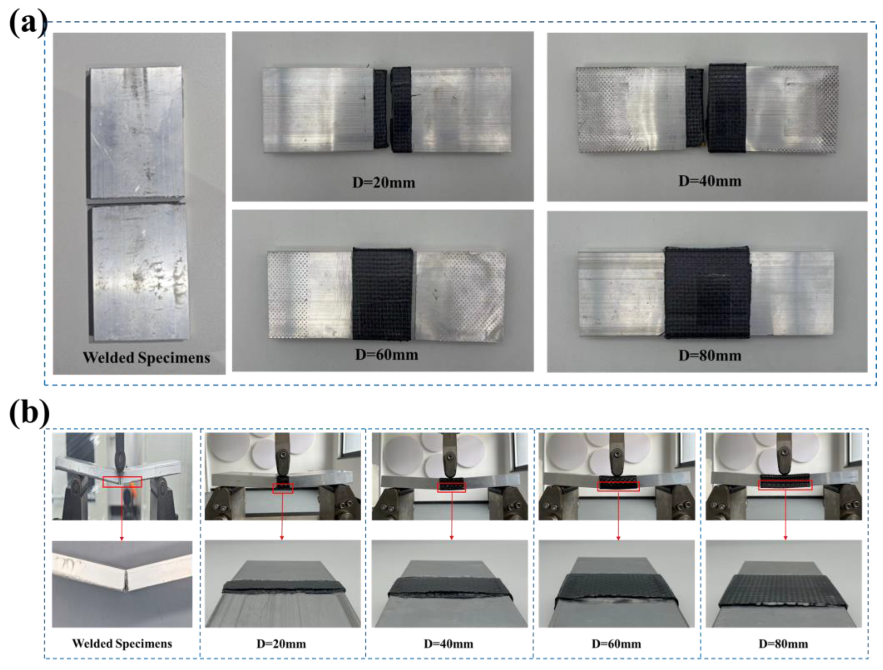
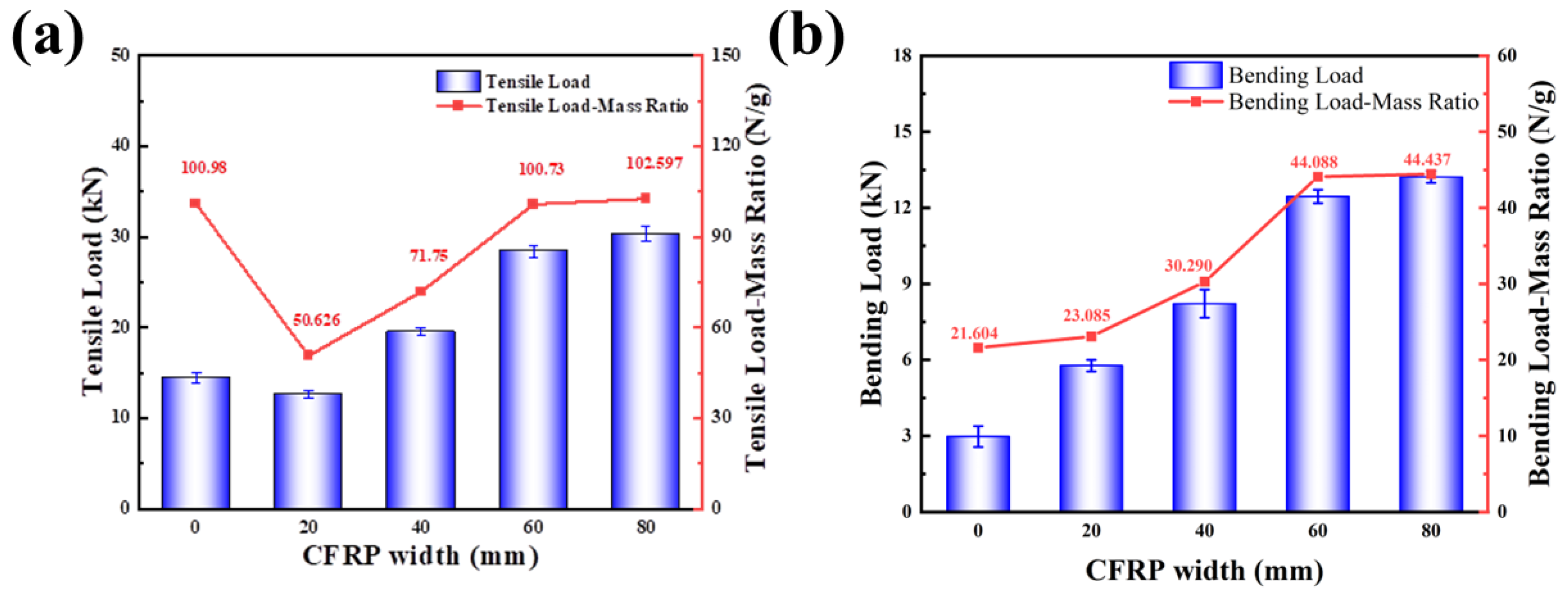
3.1. Impact of Different Widths of CFRP Sandwich Structures on the Mechanical Performance of Connectors

Figure 9 shows the failure modes of different connection specimens. “D” represents the width of the CFRP component. From Figure 9a, it can be seen that the tensile specimens failed due to the aluminum−CFRP connection at one end, resulting in slippage. When the width is relatively small, the tensile strength is lower and the specimens fail by being directly pulled apart. For wider tensile specimens, failure is characterized by slippage of the aluminum alloy after interface failure. The welded specimens exhibit failure through detachment at the weld points. Figure 9b shows that the bending failure of the connection specimens mainly occurs due to the failure of the side CFRP skin and the slippage at the CFRP−aluminum alloy interface. The welded specimens exhibit failure through cracking along one side of the weld seam, extending along the side of the specimen.
Figure 10 shows the tensile and three-point bending test results, as well as the specific strength, for connectors with varying CFRP sandwich-structure widths. The trends for tensile and bending loads both increase with the width of the CFRP component. As depicted in Figure 10a, the tensile load of the connector rises from 12.35 kN to 28.43 kN as the width (D) increases from 20 mm to 60 mm, after which the increase stabilizes. At a width of 60 mm, the specific tensile strength is comparable to that of welded connectors. As shown in Figure 10b, the bending load of the joint increases from 5.87 kN to 12.57 kN, after which the change is minimal. At this point, the bending strength increases by 114.14% compared to welding and the mass-specific bending strength increases to 206.47% of the welded connection. While increasing the width improves the mechanical performance of the connection, it also increases the mass of the structure. This explains why the specific tensile strength at 20 mm and 40 mm widths is lower than that of the welded samples. At 60 mm, the enhancement in tensile load exceeds the increase in mass, resulting in a specific strength that matches the welded level. When the width continues to increase, the load capacity improvement is minimal and the mass-specific strength remains largely unchanged.
Analysis indicates that the tensile and bending failures of pure aluminum alloy profiles are characterized by the yield deformation of the aluminum alloy. In contrast, the connection structure utilizing CFRP and aluminum alloy cured together primarily relies on the stiffness of the CFRP and the bonding effectiveness between the CFRP and aluminum alloy to achieve the desired connection. Compared to aluminum alloy profiles, CFRP has a lower density and higher strength. Additionally, due to issues like thermal deformation from welding and inherent microcrack defects, the strength of welded areas in aluminum alloys typically reaches only about 50% of the base material’s strength. Therefore, using CFRP to reinforce the aluminum alloy connection structure can significantly enhance the mechanical performance of the structure.
In tensile tests, the primary factor affecting the connection is the adhesive bond between the CFRP and the aluminum alloy interface. However, in bending conditions, due to the different loading methods, the interface is subjected to shear forces and the CFRP component primarily experiences bending loads, leading to a more significant increase in bending load capacity. When selecting the width of the CFRP component, if the width is too narrow, the interface between the CFRP and aluminum alloy is narrow, resulting in a weaker connection. Conversely, if the width is too large, further increasing the width of the CFRP when it already plays a significant role in the connection does not significantly enhance the structural strength. Instead, it increases the structural mass, raising costs and reducing the strength-to-weight ratio.

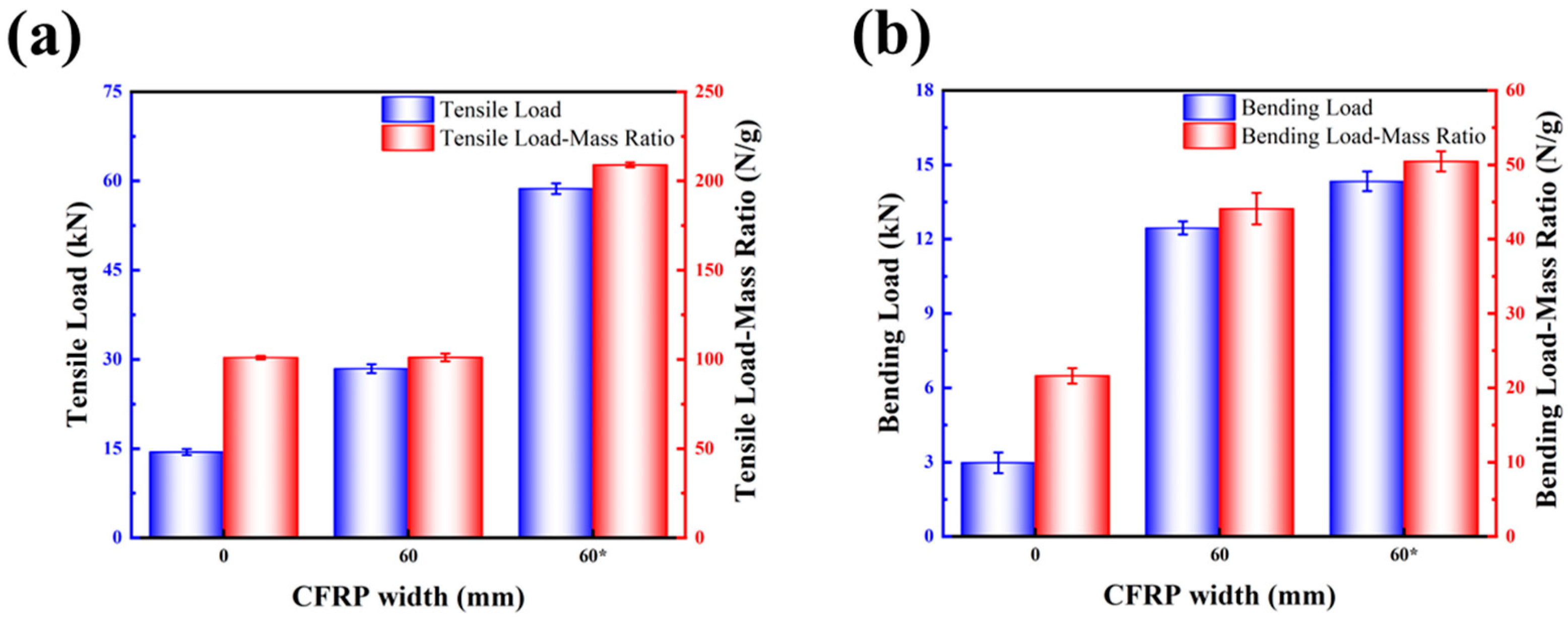
3.2. Effect of Aluminum Alloy Surface Treatment on the Mechanical Performance of CFRP Foam-Core Sandwich-Structure Connectors

Figure 11 shows the test results and mass-specific strength of welded aluminum alloy (CFRP is 0 mm), untreated sandwich-structure joints (CFRP is 60 mm), and surface-treated sandwich-structure joints (CFRP is 60* mm). Figure 11a represents the tensile test, and Figure 11b represents the bending test; the blue bars represent the test load, while the red bars represent the strength-to-weight ratio. Figure 11a shows that the maximum tensile load of the aluminum alloy joints increased from 28.43 kN to 58.71 kN after surface treatment, representing a 206.47% increase compared to the untreated connectors. Additionally, the maximum tensile load increased by 300.48% compared to metal welded structures, which had a maximum tensile load of 14.66 kN. The mass-specific strength increased by 106.78% compared to untreated aluminum alloy joints and by 106.53% compared to welded structure joints. From Figure 11b, it can be seen that after treating the aluminum alloy, the bending performance of the connectors showed a relatively small improvement compared to untreated connectors. However, compared to welded connection samples, the maximum bending load increased from 2.98 kN to 14.33 kN, an improvement of 380.87%. The bending load ratio of the connection samples increased from 21.5 N/g to 50.4 N/g, an enhancement of 134.42%.
The analysis suggests that the purpose of cooperative surface treatment is to modify the surface of the aluminum alloy, thereby improving the adhesive bond between the CFRP and the aluminum alloy interface. In composite material connection structures, there is a correlation between the tensile performance of the connectors and the interface’s adhesive performance. Therefore, surface treatment can significantly enhance the tensile performance of the connection structure. The bending performance of the connection structure is mainly related to the stiffness of the CFRP, with the interface between the CFRP and aluminum alloy playing a synergistic role. Consequently, the bending performance of the connectors is not significantly improved after surface treatment of the aluminum alloy. However, overall, compared to traditional welding connections, this method still shows a noticeable improvement.

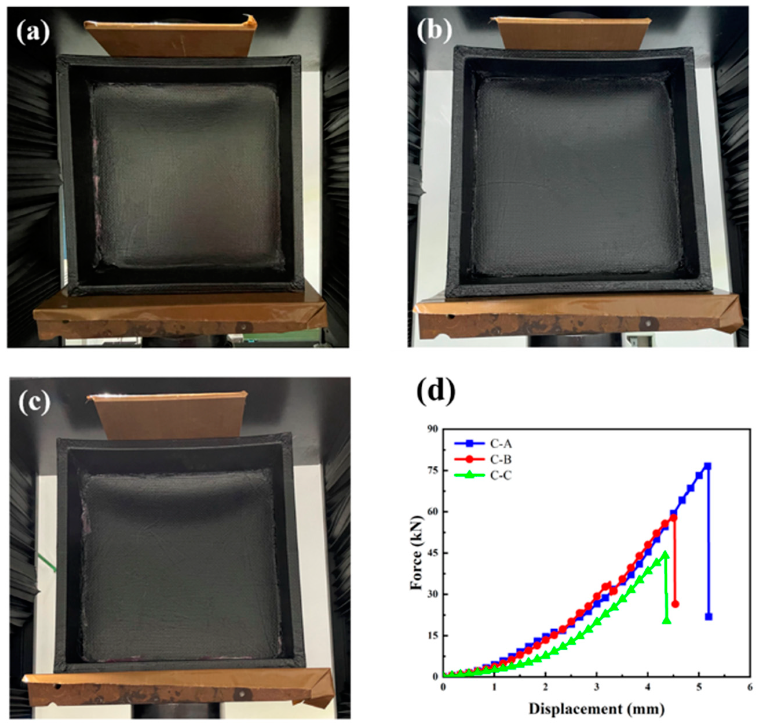
3.3. Performance Analysis of Sandwich-Structure Joint Box

To validate the impact of CFRP foam sandwich connections and surface-treated aluminum alloy on the mechanical performance of the box structure, products with different connection structures were manufactured using vacuum bag compression technology for compression testing, as shown in Figure 12a–c. In Figure 12d, C-A, C-B, and C-C represent the compression test curves for the optimized surface-treated composite connection box structure, the untreated composite connection box structure, and the welded box structure, respectively.
The test results in Table 6 reveal that the untreated composite connection (C-B) shows a significant improvement over the welded connection (C-C), with the maximum load increasing from 44.26 kN to 57.83 kN, a relative improvement of 30.66%. The specific strength also increases by 29.19%, indicating that the CFRP sandwich structure provides higher connection strength than traditional welding. The optimized surface-treated composite connection (C-A) further enhances the maximum load capacity to 77.01 kN, a 33.16% improvement over C-B and a 73.98% increase over C-C. The specific strength of C-A is improved by 33.01% compared to C-B and by 71.83% compared to C-C. This indicates that surface treatment of the aluminum alloy can significantly improve the strength of the CFRP connection structures, providing superior mechanical performance, increased safety, and reliability. When applying CFRP connection structures and surface treatment techniques to box structures, their mechanical performance is significantly enhanced.

3.4. Finite Element Simulation Analysis

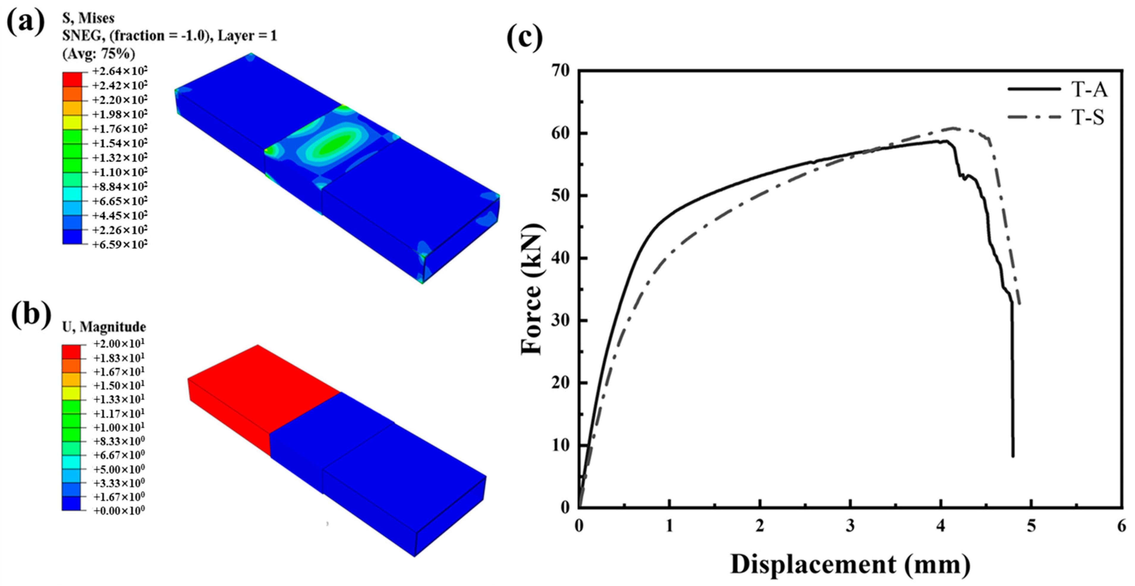
3.4.1. Finite Element Analysis of Tensile Samples

Figure 13a,b show the stress and deformation contours from the finite element analysis (FEA) of the tensile test samples. The analysis indicates that stress is primarily concentrated on the inner and outer surfaces of the CFRP−aluminum alloy connection, reflecting the bond strength of the adhesive interface. Most of the stress occurs at the tensile end of the aluminum alloy, with minimal stress or strain in the CFRP component−aluminum alloy profile interface. Figure 13c compares the simulation (T-S) and experimental (T-A) load curves for the tensile test of the CFRP−aluminum alloy connection samples. Both curves exhibit a consistent linear trend. However, the measured curve shows more fluctuations and a plateau phase after failure, likely due to imperfections in the bonding surface during manufacturing. The maximum measured load reached 58.71 kN. The simulated curve, benefiting from idealized conditions, displays a smoother load–displacement trend, with an earlier reduction in slope and a quicker decline in load after failure. The maximum simulated load was 61.57 kN, slightly higher than the measured result, with a 4.87% error margin.

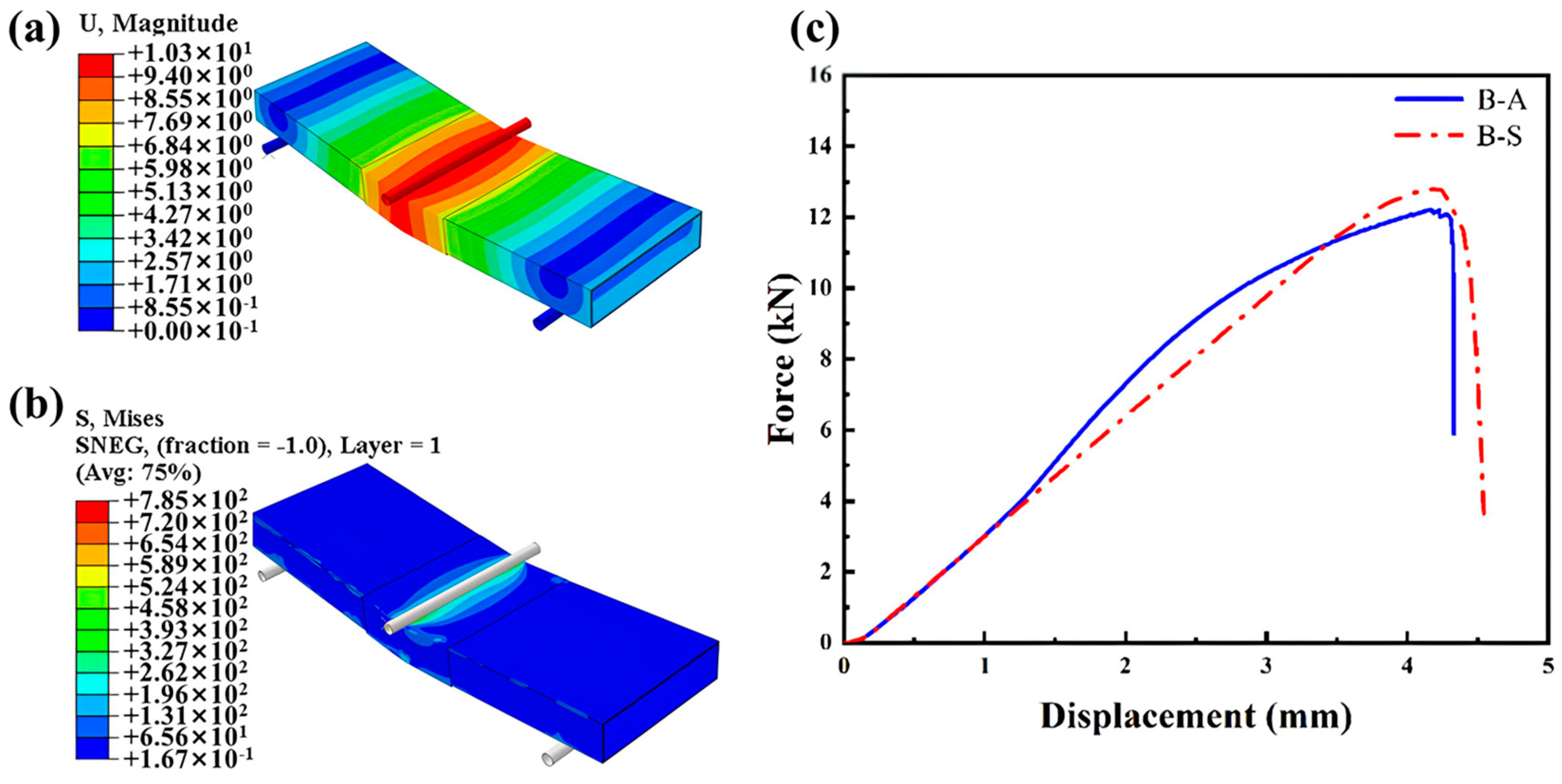
3.4.2. Finite Element Analysis of Bending Samples

Figure 14a,b show the finite element model’s calculation results. The three-point bending test reveals that stress and strain are primarily concentrated at the aluminum alloy connection in the center, effectively reflecting the connection’s strength. Figure 14c compares the simulated (B-S) and measured (B-A) load curves for the three-point bending test of CFRP/aluminum alloy connection samples. The simulated and measured curves show a consistent linear trend. However, due to the more controlled performance parameters and loading methods in the simulation, the material’s stress–strain curve is straighter, with less pronounced slope changes near the maximum load compared to the measured curve. The practical challenges in achieving ideal conditions during sample fabrication and testing result in a measured maximum load of 12.21 kN, while the simulated maximum load is 12.79 kN, yielding an error margin of 4.50%.

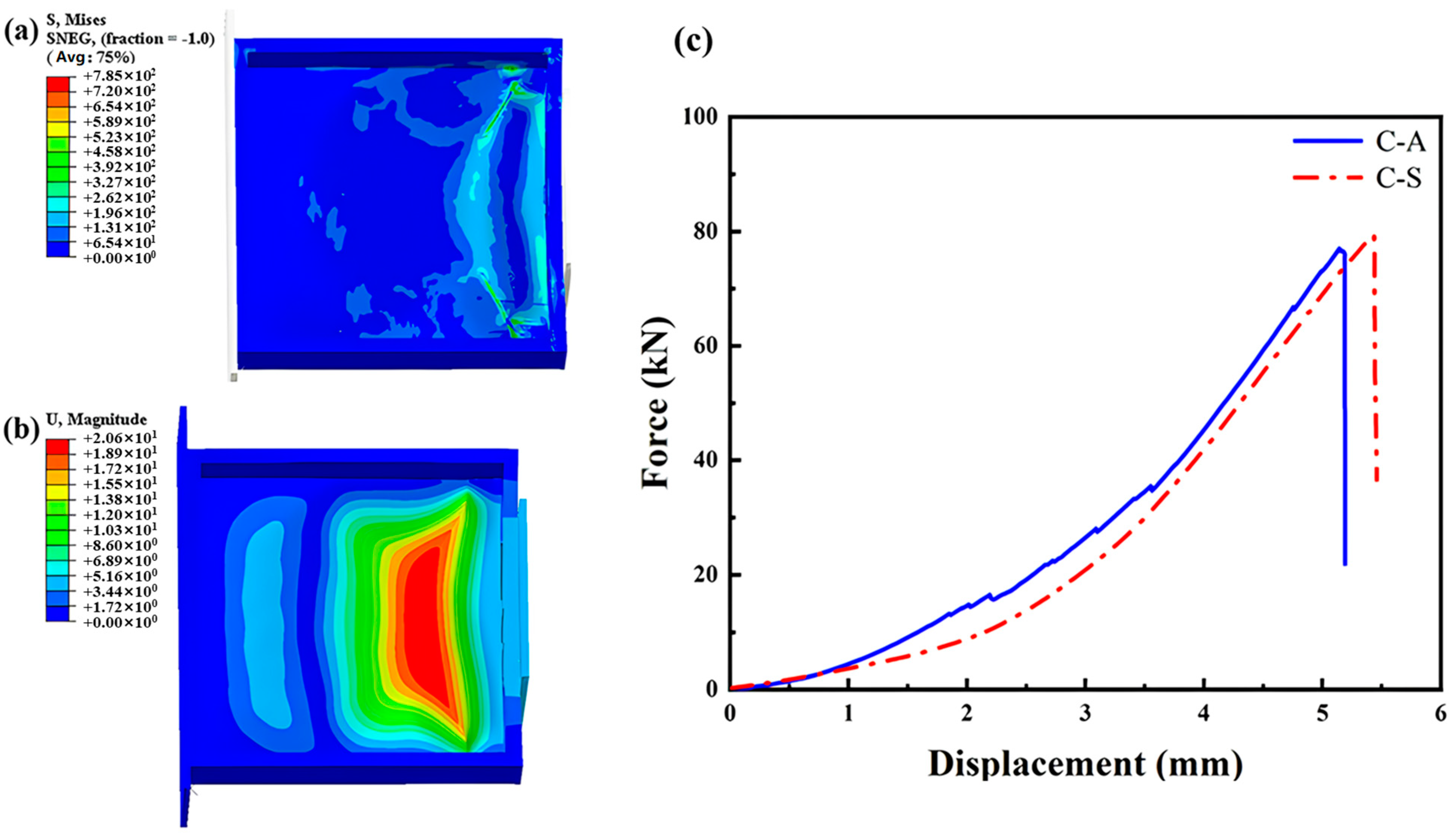
3.4.3. Finite Element Analysis of Sandwich-Structure Joint Box

Figure 15a,b shows the stress and deformation contours from the finite element analysis of the box structure model. Under compressive loading, the side beams exhibit significant displacement and bending deformation. The box bottom experiences severe inward deformation, resulting in extensive bending failure, consistent with experimental observations. The failure modes include bending and shear failure of the side beams and interface failure at the box bottom. However, the side beam connections remain intact, indicating that the structure and surface treatment effectively enhance bonding strength.
Figure 15c compares the simulation (C-S) and experimental (C-A) compression test results for the sandwich-structure joint box. The experimental curve shows load fluctuations due to the composite nature and heterogeneous structure of the CFRP material, making it more irregular. In contrast, the simulated curve is smoother, with more consistent load–displacement changes. The maximum simulated load is 79.67 kN, while the experimental maximum load is 77.01 kN, with a minor error of 3.34%. This indicates that the finite element analysis model is highly reliable for complex structures.

4. Conclusions

This paper proposes a novel CFRP−aluminum alloy composite connection method. The aluminum alloy is surface-treated using plasma and laser synergistic treatment. The CFRP prepreg is wrapped around the connection area and co-cured with the aluminum alloy through vacuum bag pressing to achieve the connection. By using CFRP for aluminum alloy composite connections and studying the effect of CFRP component width on connection performance, the optimal width of the CFRP component to enhance this connection structure was determined. Surface treatment of the aluminum alloy using the optimal synergistic treatment method further improved the connection structure strength. A simple automotive battery box lower-housing structure was fabricated and experimentally verified that this connection structure can also enhance certain components.
This paper also experimentally investigated and established a constitutive model of the aluminum alloy surface synergistic treatment and CFRP connection interface. Finite element analysis simulations were performed for the tensile, bending, and compression tests of the optimal width and surface-treated connection samples. The following conclusions were obtained:
1. Effect of CFRP Width on Connection Performance: The study explored the impact of different CFRP component widths on connection structure performance, determining that a width of 60 mm was the most suitable for this type of connection structure. Without surface treatment, the tensile load of the connectors reached 28.43 kN and the bending load reached 12.57 kN, representing increases of 93.93% and 114.14%, respectively, compared to aluminum alloy welded connections. The bending strength-to-weight ratio improved by 206.47%. The tensile performance of the connectors was primarily due to the adhesive bond between the CFRP and aluminum alloy interface, while the bending performance was mainly due to the stiffness of the CFRP components. Therefore, without surface treatment, this structure significantly enhanced the bending performance and also improved the tensile load of the connectors, although the increase in tensile strength-to-weight ratio was not substantial.
2. Surface Treatment and Connection Performance: Based on the optimal CFRP width, surface treatment of the aluminum alloy improved the interface connection between the aluminum alloy and CFRP. Experimental tests showed that the tensile load of the connectors reached 58.71 kN and the bending load reached 14.33 kN, representing increases of 206.47% and 14%, respectively, compared to untreated connectors. The strength-to-weight ratio increased by 106.53% and 12.33%, respectively. This indicates that the aluminum alloy surface synergistic treatment effectively improved the interface issues between the aluminum alloy and CFRP, enhancing the tensile performance and moderately improving the bending performance of this connection structure. For welded connectors, the tensile and bending loads increased by 300.47% and 381.30%, respectively, indicating that surface-treated connection structures significantly improve mechanical performance.
3. Application in Automotive Battery Box: This connection structure was applied to a simplified model of the lower housing of an automotive battery box. Compression tests showed that connectors using this structure had a 73.99% higher compressive load and a 71.95% higher strength-to-weight ratio compared to aluminum alloy welded connectors. This verifies the potential application of this connection structure in developing composite material battery box lower-housings, composite material seat backs, composite material trunk lids, and other automotive components, providing a design approach for connecting automotive metal components.
4. Finite Element Analysis and Model Validation: Using ABAQUS 2023 software, we explored the finite element analysis (FEA) of the composite connection structure. The study focused on establishing the constitutive model for the aluminum alloy−CFRP interface connection using the bilinear Fernando model. Through interface experiments, we identified the model’s bond−slip curve and optimized the FEA model structure. The tensile and bending tests of the connection joints were analyzed using FEA. The analysis results showed a maximum tensile load of 61.57 kN and a maximum bending load of 12.79 kN. Compared with the actual results, the error was within 5%, preliminarily validating the reliability of the simulation model. The model was then applied to the battery box structure. The FEA results matched the actual test trends and peak values, with the maximum load in the simulation analysis being 79.67 kN and the measured maximum load being 77.01 kN, resulting in an error of only 3.34%. This further verified the feasibility of the finite-element interface bonding model. These findings provide a reference for future FEA of other types of interface contacts or connection structures, contributing to the development of lightweight materials and improved connection methods in the automotive industry.
In summary, this connection structure effectively addresses the challenges of aluminum alloy welding, such as welding difficulty, high costs, significant product deformation, low joint strength, and inconsistent welding quality. This connection technique does not require advanced welding equipment and avoids issues with welding thin products. Therefore, the cost can be controlled after process adjustments. It has been experimentally verified in multiple automotive lightweight development projects and holds promise for further industrialization. This performance-enhancing method can also be applied to other related product structure studies, providing a foundation for the application of and research into hybrid metal and composite material connection structures.

Author Contributions

Conceptualization, J.Z., Y.L. and L.C.; investigation, D.K. and R.G.; methodology, J.Z., Y.Q., Z.M., M.Z. and M.Y.; supervision, Z.S.; validation, D.K.; writing—original draft, J.Z.; writing—review and editing, J.Z. All authors have read and agreed to the published version of the manuscript.

Funding

This work was supported by the Fundamental Research Funds for the Central Universities (223202023G-23), (CUSF-DH-T-2023042) and (2232024D-12).

Institutional Review Board Statement

Not applicable.

Informed Consent Statement

Not applicable.

Data Availability Statement

Data are contained within the article.

Conflicts of Interest

The authors declare no conflicts of interest.

References

  1. Jeevi, G.; Nayak, S.K.; Abdul, K.M. Review on adhesive joints and their application in hybrid composite structures. Adhes. Sci. Technol. 2019, 33, 1497–1520. [Google Scholar] [CrossRef]
  2. Shang, X.; Marques, E.A.S.; Machado, J.J.M.; Carbas, R.J.C.; Jiang, D.; Da Silva, L.F. Review on techniques to improve the strength of adhesive joints with composite adherends. Compos. Part B Eng. 2019, 177, 107363. [Google Scholar] [CrossRef]
  3. Chen, D.; Sun, G.; Jin, X.; Li, Q. Quasi-static bending and transverse crushing behaviors for hat-shaped composite tubes made of CFRP, GFRP and their hybrid structures. Compos. Struct. 2020, 239, 111842. [Google Scholar] [CrossRef]
  4. Wang, Z.; Zhang, W.; Luo, Q.; Zheng, G.; Li, Q.; Sun, G. A novel failure criterion based upon forming limit curve for thermoplastic composites. Compos. Part B Eng. 2020, 202, 108320. [Google Scholar] [CrossRef]
  5. Wang, Z.; Xie, H.; Luo, Q.; Li, Q.; Sun, G. Optimizaition for formability of plain woven carbon fiber fabrics. Int. J. Mech. Sci. 2021, 197, 106318. [Google Scholar] [CrossRef]
  6. Zhang:, X.; Chen, Y.; Hu, J. Recent advances in the development of aerospace materials. Prog. Aerosp. Sci. 2018, 97, 22–34. [Google Scholar] [CrossRef]
  7. An, J. Study on Toughening Modification of Flame Retardant Composite Materials Based on PBT. Bachelor’s Thesis, Lanzhou University of Technology, Lanzhou, China, 2021. [Google Scholar]
  8. Xie, G.S.; Huang, Z.B.; Zhao, X.B.; Qin, P.F.; Lao, B. Discussion on Lightweight Design of Automobile Bodies. Automot. Parts 2023, 80–84. [Google Scholar]
  9. Kunická, L.; Kocich, R.; Lowe, T.C. Advances in metals and alloys for joint replacement. Prog. Mater. Sci. 2017, 88, 232–280. [Google Scholar] [CrossRef]
  10. Taub, A.; De Moor, E.; Luo, A.; Matlock, D.K.; Speer, J.G.; Vaidya, U. Materials for Automotive Lightweighting. Annu. Rev. Mater. Res. 2019, 49, 327–359. [Google Scholar] [CrossRef]
  11. Heinz, A.; Haszler, A.; Keidel, C.; Moldenhauer, S.; Benedictus, R.; Miller, W.S. Recent development in aluminum alloys for aerospace applications. Mater. Sci. Eng. A 2000, 280, 102–107. [Google Scholar] [CrossRef]
  12. Tian, Y.L. Trends in Lightweight Material Technology and the Application and Challenges of Composite Materials in New Energy Vehicles. In Proceedings of the “Innovative Materials Leading New Opportunities in Automotive Development”—2019 China Automotive Materials (Xiqing) International Forum, Tianjin, China, 27 March 2019; pp. 500–510. [Google Scholar]
  13. Lu, S.K.; Hua, D.X.; Li, Y.; Cui, F.Y.; Li, P.Y. Stiffness calculation model of thread connection considering friction factors. Math. Probl. Eng. 2019, 2019, 8424283. [Google Scholar] [CrossRef]
  14. Yu, H.Y.; Li, J.X.; Zhou, G.X. Tensile Performance of Bolt Connections between Carbon Fiber Composite Materials and High-Strength Steel Plates. J. Tongji Univ. (Nat. Sci. Ed.) 2018, 46, 680–686+700. [Google Scholar]
  15. Xiao, Y.; Ishikawa, T. Bearing strength and failure behavior of bolted composite joints (part I: Experimental investigation). Compos. Sci. Technol. 2005, 65, 1022–1031. [Google Scholar] [CrossRef]
  16. Liu, H.; Liu, X.; Chen, Z.; Ouyang, Y.; Yin, J. Mechanical properties of bolted connections for aluminum alloy structures at elevated temperatures. Thin-Walled Struct. 2020, 157, 107067. [Google Scholar] [CrossRef]
  17. Xiong, Y.J.; Zheng, Y.P.; Xia, X.S.; Yang, B.N. Study on the Performance of Metal-Composite Material Lap Joint Structures. Fiberglass/Compos. Mater. 2019, 59–65. [Google Scholar]
  18. Liu, Y.; Zhuang, W.; Luo, Y.; Xie, D.; Mu, W. Joining mechanism and damage of self-piercing riveted joints in carbon fibre reinforced polymer composites and aluminium alloy. Thin-Walled Struct. 2023, 182, 110233. [Google Scholar] [CrossRef]
  19. Wang, J.; Zhang, G.; Zheng, X.; Li, J.; Li, X.; Zhu, W.; Yanagimoto, J. A self-piercing riveting method for joining of continuous carbon fiber reinforced composite and aluminum alloy sheets. Compos. Struct. 2021, 259, 113219–113228. [Google Scholar] [CrossRef]
  20. Lee, C.J.; Lee, J.M.; Ryu, H.Y.; Lee, K.H.; Kim, B.M.; Ko, D.C. Design of hole-clinching process for joining of dissimilar materials-Al6061-T4 alloy with DP780 steel, hot-pressed 22MnB5 steel, and carbon fiber reinforced plastic. J. Mater. Process. Technol. 2014, 214, 2169–2178. [Google Scholar]
  21. Li, H.; Liu, X.S.; Zhang, Y.S.; Senkara, J.; Li, G.Y.; Ma, M.T. Challenges, Trends, and Advances in Joining Technologies for Dissimilar Materials in New Energy Electric Vehicles. Mater. Rev. 2019, 33, 3853–3861+3881. [Google Scholar]
  22. Ramezani, F.; Nunes, P.D.P.; Carbas, R.J.C.; Marques, E.A.S.; da Silva, L.F.M. The Joint Strength of Hybrid Composite Joints Reinforced with Different Laminates Materials. J. Adv. Join. Process. 2022, 5, 100103–100113. [Google Scholar] [CrossRef]
  23. Ni, J.; Min, J.; Wan, H.; Lin, J.; Wang, S.; Wan, Q. Effect of adhesive type on mechanical properties of galvanized steel/SMC adhesive-bonded joints. Int. J. Adhes. 2019, 97, 102482. [Google Scholar] [CrossRef]
  24. Qin, J.J. Exploration of the Process Flow for Metal Adhesive Bonding Pretreatment; Modern Enterprise: Seattle, WA, USA, 2019; pp. 146–147. [Google Scholar]
  25. Sun, G.; Xia, X.; Liu, X.; Luo, Q.; Li, Q. On quasi-static behaviors of different joint methods for connecting carbon fiber reinforce plastic (CFRP) laminate and aluminum alloy. Thin-Walled Struct. 2021, 164, 107657. [Google Scholar] [CrossRef]
  26. Joesbury, A.M.; Colegrove, P.A.; Van Rymenant, P.; Ayre, D.S.; Ganguly, S.; Williams, S. Weld-bonded stainless steel to carbon fiber-reinforced plastic joints. J. Mater. Process. Technol. 2018, 251, 241–250. [Google Scholar] [CrossRef]
  27. Murray, R.E.; Roadman, J.; Beach, R. Fusion joining of thermoplastic composite wind turbine blades: Lap-shear bond characterization. Renew. Energy 2019, 140, 501–512. [Google Scholar] [CrossRef]
  28. Xiao, J.; Min, J.Y.; Lin, J.P.; Zhang, J. A Review of the Bonding Techniques Between Polymer Matrix Composites and Metals. Automot. Abstr. 2021, 543, 32–38. [Google Scholar]
  29. Kawahito, Y.; Niwa, Y.; Terajima, T.; Katayama, S. Laser direct joining of glassy metal Zr55Al10Ni5Cu30 to engineering plastic polyethylene terephthalate. Mater. Trans. 2010, 51, 1433–1436. [Google Scholar] [CrossRef]
  30. Lin, J.; Zhang, J.; Min, J.; Sun, C.; Yang, S. Laser-assisted conduction joining of carbon fiber reinforced sheet molding compound to dual-phase steel by a polycarbonate interlayer. Opt. Laser Technol. 2021, 133, 106561. [Google Scholar] [CrossRef]
  31. Suresh, S.; Venkatesan, K.; Natarajan, E. Influence of SiC Nanoparticle Reinforcement on FSS Welded6061-T6 Aluminum Alloy. J. Nanomater. 2018, 1, 7031867. [Google Scholar]
  32. Sonoya, K.J.; Fukui, K.; Suzuki, M. Effect of Welding Conditions of Spot Welded Zone on the Tensile Strength about Aluminum Alloy (A6061). Univers. J. Mech. Eng. 2016, 4, 8–18. [Google Scholar] [CrossRef]
  33. Prussak, R.; Stefaniak, D.; Kappel, E.; Hühne, C.; Sinapius, M. Smart cure cycles for fiber metal laminates using embedded fiber Bragg grating sensors. Compos. Struct. 2019, 213, 252–260. [Google Scholar] [CrossRef]
  34. Zhu, W. Study on the Interface Control Mechanism and Performance of Al/CFRP/Al Laminates. Master’s Thesis, Yanshan University, Qinhuangdao, China, 2021. [Google Scholar]
  35. Park, S.Y.; Choi, W.J.; Choi, H.S.; Kwon, H. Effects of surface pre-treatment and void content on GLARE laminate process characteristics. J. Mater. Process. Technol. 2010, 210, 1008–1016. [Google Scholar] [CrossRef]
  36. Mu, W.L.; Na, J.X.; Qin, G.F.; Tan, W.; Gao, Y.; Shen, H. Durability Study of CFRP-Aluminum Alloy Adhesive Joints at Extreme Temperatures. Automot. Eng. 2020, 42, 985–992. [Google Scholar]
  37. Boon, Y.D.; Joshi, S.C.; Ong, L.S. Effects of mechanical surface treatment on bonding between aluminum and carbon/epoxy composites. Procedia Eng. 2017, 184, 374–386. [Google Scholar] [CrossRef]
  38. Nemani, S.K.; Annavarapu, R.K.; Mohammadian, B.; Raiyan, A.; Heil, J.; Haque, M.A.; Abdelaal, A.; Sojoudi, H. Surface modification of polymers: Methods and applications. Adv. Mater. Interfaces 2018, 5, 1801247. [Google Scholar] [CrossRef]
  39. Song, Y.; Shi, G.Q.; Dong, Z.D.; Tang, X.; Han, B.N. Review of Common Surface Treatment Methods in Aerospace Applications. Electron. Prod. Reliab. Environ. Test. 2019, 37, 78–81. [Google Scholar]
  40. Liu, X. Fundamental Research on the Mechanism and Application of Ionized Airflow Assisted Cutting. Master’s Thesis, Dalian University of Technology, Dalian, China, 2012. [Google Scholar]
  41. Bónová, L.; Zhu, W.; Patel, D.K.; Krogstad, D.V.; Ruzic, D.N. Atmospheric pressure microwave plasma for aluminum surface cleaning. J. Vac. Sci. Technol. A Vac. Surf. Film. 2020, 38, 023002. [Google Scholar] [CrossRef]
  42. Munoz, J.; Bravo, J.A.; Calzada, M.D. Aluminum metal surface cleaning and activation by atmospheric-pressure remote plasma. Appl. Surf. Sci. 2017, 407, 72–81. [Google Scholar] [CrossRef]
  43. Li, C.Q.; Dong, H.B.; Zou, Y.G.; Zou, X.H. The Effect of Low-Temperature Air Plasma Treatment on the Adhesion Performance of Aluminum Alloy Surfaces. China Surf. Eng. 2017, 30, 34–42. [Google Scholar]
  44. GB/T 228.1-2010; Metallic Materials—Tensile Testing—Part 1: Method of Test at Room Temperature. Standardization Administration of China: Beijing, China, 2010.
  45. GB/T 232-2010; Metallic Materials—Bend Test Method. Standardization Administration of China: Beijing, China, 2010.
  46. Wang, H.T.; Wu, G.; Dai, Y.T.; He, X.Y. Determination of the bond–slip behavior of CFRP-to-steel bonded interfaces using digital image correlation. J. Reinf. Plast. Compos. 2016, 35, 1353–1367. [Google Scholar] [CrossRef]
  47. Menzemer, C.C.; Fei, L.; Srivatsan, T.S. Failure of bolted connections in an aluminum alloy. J. Mater. Eng. Perform. 1999, 8, 197–204. [Google Scholar] [CrossRef]
Figure 1. (a) Plasma surface treatment schematic; (b) laser surface treatment schematic.
Coatings 14 00785 g001
Figure 2. The process for making CFRP connection specimens. (a) Fabrication of internal CFRP components; (b) assembly (c); laying of external CFRP.
Coatings 14 00785 g002
Figure 3. (a) Vacuum bag molding; (b) curing schedule; (c) molded sample.
Coatings 14 00785 g003
Figure 4. Process flow diagram for CFRP connection structure casing forming.
Coatings 14 00785 g004
Figure 5. Schematic Diagram of Specimen Dimensions.
Coatings 14 00785 g005
Figure 6. (a) Experimental curve of the joint under synergistic surface treatment; (b) constitutive model curve of the joint interface with synergistic treatment on the aluminum alloy surface.
Coatings 14 00785 g006
Figure 7. Tensile test model of CFRP−aluminum alloy composite joint structure: (a) meshing; (b) boundary conditions; (c) distributed load; bending test model of CFRP−aluminum alloy composite joint structure: (d) meshing; (e) boundary conditions; (f) distributed load.
Coatings 14 00785 g007
Figure 8. Finite element model of CFRP−aluminum alloy composite structure box: (a) meshing; (b) boundary conditions; (c) distributed load.
Coatings 14 00785 g008
Figure 9. Failure modes of composite joints with different CFRP widths and welded structures: (a) tensile failure of the joints; (b) bending failure of the joints.
Coatings 14 00785 g009
Figure 10. (a) Tensile Test Results and Specific Strength, (b) bending test results and specific strength.
Coatings 14 00785 g010
Figure 11. It shows the test results and strength-to-weight ratio for welded (0), untreated connection structures (60), and cooperatively treated structures (60*): (a) tensile test; (b) bending test.
Coatings 14 00785 g011
Figure 12. Compression tests and experimental load curves for different structural boxes: (ac) represent the welded structure, the box with untreated connection structure, and the box with surface-treated connection structure, respectively. (d) represents the test experimental load curve.
Coatings 14 00785 g012
Figure 13. (a) Stress contour of tensile sample; (b) deformation contour of tensile sample, (c) comparison of simulated and measured load curves for tensile test.
Coatings 14 00785 g013
Figure 14. (a) Deformation contour of bending sample; (b) stress contour of bending sample; (c) comparison of simulated and measured load curves for bending test.
Coatings 14 00785 g014
Figure 15. (a) Compression stress cloud diagram of the box structure, (b) compression deformation cloud diagram of the box structure, (c) comparison of compression simulation and experimental measurement of the box structure.
Coatings 14 00785 g015
Table 1. Main experimental raw materials.
Material NameSpecificationManufacturer
Aluminum Alloy Profiles6061 (Custom-made workpieces)Jiangsu Annan Sai Metal Products Co., Ltd. (Nanjing, China)
Carbon Fiber Plain-Weave PrepregT700-12KToray Industries, Co., Ltd. (Tokyo, Japan)
PET Foam (Polyethylene terephthalate)GURIT G-PETJiaxing ZH Composites Co., Ltd. (Jiaxing, China)
AcetoneWF330Shanghai Lingfeng Chemical Reagent Co., Ltd. (Shanghai, China)
Expanding FoamHR320Xiamen Haor New Materials Co., Ltd. (Xiamen, China)
Vacuum Bag FilmLVF230BShanghai LIGO Technology Co., Ltd. (Shanghai, China)
Release FilmLRF230BShanghai LIGO Technology Co., Ltd. (Shanghai, China)
Table 2. Main equipment and instruments.
NameModelManufacturer
UV Laser Marking Machine3SUV-3Shanghai Sanshu Industrial Co., Ltd. (Shanghai, China)
Atmospheric Plasma MachineSPA2800HDongguan Shengding Precision Instruments Co., Ltd. (Dongguan, China)
Universal Testing MachineCriterion40MTS Systems Corporation, USA, Co., Ltd. (Eden Prairie, MN, USA)
Table 3. Surface treatment parameters.
ParameterLaser TreatmentPlasma Treatment
Laser Frequency (kHz)10.763/
Scanning Speed (mm/s)102.719/
Scan Line Spacing (mm)0.115/
Treatment Time (s)/173.132
Treatment Distance (mm)/5.821
Gas Flow Rate (L/h)/597.383
Table 4. Material parameters of CFRP.
ParameterValueUnit
E162,000MPa
E258,000MPa
E36900MPa
ν120.04
ν130.3
ν230.3
G127700MPa
G132700MPa
G232700MPa
Table 5. Test values of specimen intrinsic model parameters.
NumberPeak Slip δ1
(mm)
Maximum Shear Stress τf
(MPa)
Maximum Slip δf
(mm)
Bond Stiffness τf/δ1
(MPa/mm)
Fracture Energy Gf
(N/mm)
C-10.02221.0010.124956.4601.300
C-20.03021.4290.140723.9531.503
C-30.02921.3850.129743.4311.374
C0.02721.2720.131794.4871.392
Table 6. Test results of the main structure of the case under different batteries.
ProductC-AC-BC-C
Maximum Compression Load (kN)77.0157.8344.26
Specific Strength (N/g)17.3513.0410.09
Disclaimer/Publisher’s Note: The statements, opinions and data contained in all publications are solely those of the individual author(s) and contributor(s) and not of MDPI and/or the editor(s). MDPI and/or the editor(s) disclaim responsibility for any injury to people or property resulting from any ideas, methods, instructions or products referred to in the content.

