Article

Durable and High-Temperature-Resistant Superhydrophobic Diatomite Coatings for Cooling Applications

1
IN+ Center for Innovation, Technology and Policy Research, Instituto Superior Técnico, Universidade de Lisboa, Avenida Rovisco Pais, 1049-001 Lisboa, Portugal
2
CINAMIL—Military Academy Research Center, Department of Exact Sciences and Engineering, Portuguese Military Academy, 2720-113 Amadora, Portugal
*
Author to whom correspondence should be addressed.
Coatings 2024, 14(7), 805; https://doi.org/10.3390/coatings14070805
Submission received: 30 May 2024 / Revised: 18 June 2024 / Accepted: 24 June 2024 / Published: 28 June 2024

Abstract

:
The present work is aimed at the development of superhydrophobic coatings and surfaces with enhanced robustness and boiling temperature resistance. We will address the synthesis method of the coatings, which was based on the preparation of a composite of silanized diatomite particles embedded in epoxy resin. After the synthesis of the composite solution, it was applied by dip-coating in stainless steel substrates and submitted to a post-treatment cure in an oven. The method proved to be a comparatively fast and simple one. Then, the substrate/coating sets were characterized using different techniques, including Fourier transform infrared spectroscopy and scanning electron microscopy, and their water contact angle and roughness were measured. Apart from this, the physical and chemical robustness of the sets was also tested using diverse resistance tests like adhesion strength, abrasion resistance, resistance to strong acids and bases, and resistance to boiling water. The main results are that we obtained robust coatings, with wettability defined by water contact angles above 150°. Also, the synthesized coatings revealed good resistance to boiling water, as their properties were almost unchanged after the completion of a long period of tests. The characterization of the produced coatings suggested their propensity to be explored for use in water boiling surfaces and interfaces for cooling purposes in boiling heat transfer systems.

1. Introduction

Surface–water interactions can be classified into four different surface types, which are ranked according to decreasing intermolecular interactions with water as follows: superhydrophilic, hydrophilic, hydrophobic, and superhydrophobic. Superhydrophilic surfaces combine hydrophilic chemistry and micro-/nanostructures and have contact angles tending to zero degrees. Hydrophilic surfaces have hydrophilic chemistry and contact angles between 0 and 90°, hydrophobic surfaces have hydrophobic chemistry and contact angles between 90° and 120°, and superhydrophobic surfaces have hydrophobic chemistry and micro-/nano-scaled structures with contact angles from 150° to 180°. Due to roughness features at the nanometer-to-micrometer scale and material that is chemically hydrophobic, the water does not interact with a superhydrophobic surface. If the ambient pressure is sufficiently small, the cavities between features will not be filled with water, and the surface is said to be in the Cassie state. This state is prerequisite for many unique superhydrophobic surface characteristics. The wettability of a surface can be defined as the ability of a liquid to wet it, and this can be determined using contact angle measurements. The contact angle is the three-phase contact point of the solid–liquid–air interface, and its value varies from one surface material to the other and is affected by the surface properties.
When exploring chemical surface modification, the free energy of the surface may increase or decrease, causing the liquid droplet to spread completely or hover over the surface, respectively. Moreover, the micro-/nanostructured hierarchical materials possess increased specific surface areas, which can affect the wettability of the surfaces. Apart from this, surface modification by binding low-surface energy chemicals makes the water droplet hover over the surface. Nonetheless, the production of micro- and nanostructures, including nanostructures and nanoparticles, enhances the surface free energy, providing high capillary force for the incursion of the fluid [1]. According to the Wenzel theory, roughness has an influence on both hydrophilic and hydrophobic surfaces. The effect of surface modification at the micro- and nanoscales influences its wettability, which is being studied with several materials.
Superhydrophobic coatings can be synthesized using silane-treated diatomaceous earth with polymeric binders, such as polyurethane or epoxy resins. Diatoms are unicellular algae of the class Bacillariophyceae of Phylum bacillariophyta [2]. Diatoms extract silicon from water to produce their exoskeletons, which are called frustules or hydrated silica shells [3]. When they are being produced, their tiny shells sink, and with time, these shells form layers of fossil deposits, which are known as diatomaceous earth (DE) or Kieselgur. Each three-dimensional DE structure contains millions of microscopic, hollow, perforated cylindrical, and disk-shaped shells. The resulting DE is an inert, highly porous, lightweight, and thermally resistant material. Naturally existing DE has a hydrophilic character, and chemically modified DE has been used in materials for superhydrophobic coatings [4], metal adsorbents [5], and drug delivery processes [6]. Surfaces that form static water contact angles superior to 150° and have sliding angles less than 10° are defined as superhydrophobic surfaces. The superhydrophobicity of a solid surface can be determined using its chemical composition and micro–nano hierarchical texture. Modifying a surface with low-energy chemical groups can effectively increase the water contact angle of a solid surface. Surfaces with CF2 and CF3 groups generally have low surface energies with contact angles of about 120° on a flat surface [7]. Roughening the surface may result in contact angles as high as 160° to 175°, and the surfaces become non-wettable. These superhydrophobic coatings are water-repellent and self-cleaning and can be used in many applications, like heat transfer enhancement practices, anti-icing, and anti-fogging. There are many ways to fabricate superhydrophobic surfaces, including plasma etching [8], graft-on-graft polymerization [9], chemical vapor deposition [10], lithography [11], sol–gel processing [12], and the self-assembly of low-surface energy materials. Nonetheless, some of these techniques are complex and require expensive equipment. In this scenario, it is of relevance to develop a facile and cost-effective methodology for synthesizing superhydrophobic surfaces. The use of low-cost materials, such as diatomaceous earth particles, is obviously worth consideration for that purpose. Our objective was to produce superhydrophobic coatings using fluorosilane-/aminosilane-treated diatomaceous earth particles (DE) with polymeric binders with low volatile organic contents. DE has already been made into superhydrophobic particles through a variety of novel chemistries. For instance, Puretskiy et al. [13] demonstrated that a hydrophobic polymer could be grafted from DE to make superhydrophobic anti-icing materials. Sticking the particles to the top of epoxy coatings improved the mechanical properties of the DE layer. However, the manufacturing process was somewhat complex and not scalable. Also, Oliveira et al. [14] and Polizos et al. [15] have confirmed that the fluorosilanes grafted to DE could impart a superhydrophobic nature to the diatomaceous earth particles. Also, it was demonstrated that coatings with treated diatomite and polydimethylsiloxane could perform better with the addition of graphene oxide [4]. On the other hand, Perera et al. [16] determined the water contact angles as a function of the fluorocarbon fraction on diatomite and the particle loadings of treated DE in the final coating solution. The contact angles exceeded 150° for coatings with at least a 0.02 fluorocarbon fraction (mass of fluorosilane/mass of particle) on the DE and with 0.2 particle loadings (mass of treated particles/mass of coating). The water contact angles of the surfaces were dependent on the nature of the binder below 0.2 particle loadings of the superhydrophobic diatomite particles but were independent of the type of the binder after achieving superhydrophobicity. The results were consistent with superhydrophobicity resulting from the migration of superhydrophobic DE moving to and covering the surfaces completely. Whereas most of the experimental works have shown that the superhydrophobic coatings could be produced employing specific formulations, very few data have been published about the influencing factors of the nanoparticles and the performance of the fabricated coatings. Accordingly, to manufacture more effective coatings, additional efforts should be made to better understand, for instance, the effect on the superhydrophobicity of the coatings of the number of grafted fluorocarbons in the DE powder and/or of the particle loadings of treated DE in the final coating solutions. In addition, the impact of the different binders should also be the focus of reported work on the matter.
In this context, surface modification to alter topography and wettability has been explored to improve the pool boiling heat transfer [17]. The published studies indicate that the use of surfaces modified at the nano/micro scale results in a noticeable heat transfer enhancement and a decreased superheat level for a given heat flux. At the same time, the stability and durability of the fabricated coatings remain important issues, often limiting the implementation of one or another surface modification technique in practical large-scale applications, as many of the devised surfaces have shown mechanical fragility and do not withstand high temperatures and/or thermal stress, mostly losing their wetting properties. For instance, some coatings were found to possess poor mechanical robustness [18], only moderate durability in severe vapor environments [19], a strong decrease in the contact angle after abrasion resistance cycling [20], and other practical limitations like an excessive fabrication time for the coatings to achieve superhydrophobicity [21].
Our work aimed at the development of superhydrophobic coatings to be applied over AISI 304 stainless steel foil substrates, as they are mechanically robust, high-temperature-resistant, and durable under pool boiling conditions. For this purpose, the synthesis of the base materials of the coatings was based on the silylation of suspensions of diatomite, like the one carried out by Kucuk et al. [22]. To promote better adhesion of the coatings on the substrate, the resulting dried nanopowder was added to a binder solution made of epoxy resin composed of bisphenol A diglycidyl ether and tetraethylenepentamine (DGEBA/TEPA), according to a procedure like the one described by Yuan et al. [23]. The final coating used in this work was a formulation of diatomite nanoparticles that underwent silylation with aminopropyltriethoxysilane (APTES) and perfluoroctyltrichlorosilane (PFOTS), to which was then added an epoxy resin binder. After the dip-coating of stainless-steel foil samples in the final coating solution, the foil samples were post-cure treated according to a well-defined temperature and stage time in an oven to obtain smooth, homogeneous, and strong adherent coatings. The first sections of the present work describe the materials and methods used for the synthesis of the diatomite silane functionalized superhydrophobic coatings. Section 2 describes the characterization of the coatings according to different techniques. Section 3 presents the coating durability assays and corresponding qualitative and quantitative findings. Finally, the concluding remarks are described, and suggestions for further research are given.

2. Materials

Table 1 summarizes the fundamental materials used in this experimental work.

3. Coating Synthesis Procedures

3.1. General Aspects

To produce the coatings, we prepared two different binder solutions of epoxy (DGEBA/TEPA) and polystyrene. Nonetheless, the latter did not provide a reasonable adhesion to the stainless steel substrate. The epoxy binder solutions were prepared by thoroughly mixing a stoichiometric amount of epoxy resin and curing agent in tetrahydrofuran. Two different sets of testing samples were prepared. The first set was a series of coatings made from the treated diatomite samples with different amounts of fluorosilane. The treated diatomite particles with different amounts of fluorosilane were then employed to produce epoxy-bonded coatings with 0.25, 0.35, and 0.45 particle loadings. The particle loadings were determined as the fractions of the mass of the diatomite to the mass of the diatomite plus the epoxy resin. In addition, the fluorocarbon fraction (considered in this work as the total fraction of fluorosilane plus aminosilane) on the diatomite was expressed as the mass fraction of the fluorocarbon to the total mass of treated particles, i.e., diatomite plus fluorocarbon. This fluorocarbon fraction was selected based on having enough fluorosilane for the sample to be superhydrophobic. Moreover, to improve the coating adhesion to the substrate, the latter was chemically cleaned and etched with acetone and ultra-sonicated with nitric acid and hydrogen peroxide prior to the coating steps, ensuring that the applied superhydrophobic coating would adhere better to the hydrophilic substrate. To obtain the nanopowder, para-toluenesulfonic acid was added as a surfactant to facilitate the adhesion of the fluorosilane PFOTS to the diatomite nanopowder. The fluorosilane was added to impart superhydrophobic character to the coating. After that, the aminosilane APTES was added to produce a chemical surface roughness to the nanopowders and to better affix the fluorosilane PFOTS. After the preparation of the polymeric binders like the epoxy resin, the binders were blended with the sililated nanopowders and applied over the substrate by dip-coating. After air drying the coating, the samples were post-cure treated to improve adhesion to the stainless steel substrate.

Experimental Procedure with Epoxy Resin as Binder

The experimental protocol to synthesize the diatomite (DE) sililated with PFOTS and APTES and bonded with epoxy resin (DGEBA/TEPA) involved the following steps and tasks:
Step 1—Preparation of the substrate:
  • Rinsing of the surface of the stainless steel with acetone;
  • Ultra-sonication at 100 W of the substrate with nitric acid for 10 min;
  • Ultra-sonication at 100 W of the surface of the substrate with hydrogen peroxide for 10 min;
  • Drying of the stainless steel substrate with an air jet.
Step 2—Obtaining the PFOTS–DE solution:
  • Mix 8 g of DE, 80 mL of toluene, and 0.1 g of para-toluenesulfonic acid in a glass beaker or vial;
  • Gradual addition of 1.7 g (≈1 mL) of PFOTS (perfluoroctyltrichlorosilane) and mixing by vigorous magnetic stirring at 50 °C for 12 h;
  • Rinse twice with 20 mL of hexane and discard the supernatants.
Step 3—Obtaining the PFOTS–APTES–DE solution:
  • Addition of 30 mL of toluene;
  • Gradual addition of 0.75 g (≈0.8 mL) of APTES (amino-propyltriethoxysilane) and mixing by vigorous magnetic stirring at 60 °C for 12 h and discarding of the supernatants;
  • Double rinsing of the mixture once with 20 mL of hexane and once with 20 mL of ethanol.
Step 4—Obtaining the EPOXY solution:
  • By stoichiometric analysis (amine equivalent weight) mixing of 17 parts of TEPA for 100 parts of DGEBA;
  • Addition into a glass beaker of 25 mL (29 g) of DGEBA and 5 mL (5 g) of TEPA;
  • Addition of 23 mL of THF and mixing by vigorous magnetic stirring at room temperature (minimum ratio of 0.3 g to 1 mL of THF according to findings; considered ratio of 1.5 g–1 mL of THF: 23 mL THF for 34 g DGEBA/TEPA).
Step 5—Obtaining the DE–PFOTS–APTES–EPOXY solution:
  • Mixing the DE–PFOTS–APTES solution with the EPOXY solution in a glass beaker at room temperature.
Step 6—Applying the EPOXY–PFOTS–APTES–DE coating:
  • Immersion of the clean substrate into the EPOXY–PFOTS–APTES–DE solution for 5 min before withdrawal for the first dip-coating and for 30 s before withdrawal for the four subsequent immersions;
  • Air drying of the substrate after each immersion at room temperature for 1 min.
Step 7—Heat treatment of the coating/substrate set:
  • Air drying of the coating/substrate set at room temperature for 24 h;
  • Heat treatment of the coating/substrate set in an oven at 130 °C for 2 h.
Figure 1 schematically illustrates the main steps of the coating synthesis procedure.
Figure 2 shows the substrate before and after etching and the different produced coatings.

4. Results and Discussion

4.1. Characterization of the Coatings

4.1.1. Fourier Transform Infrared Spectroscopy
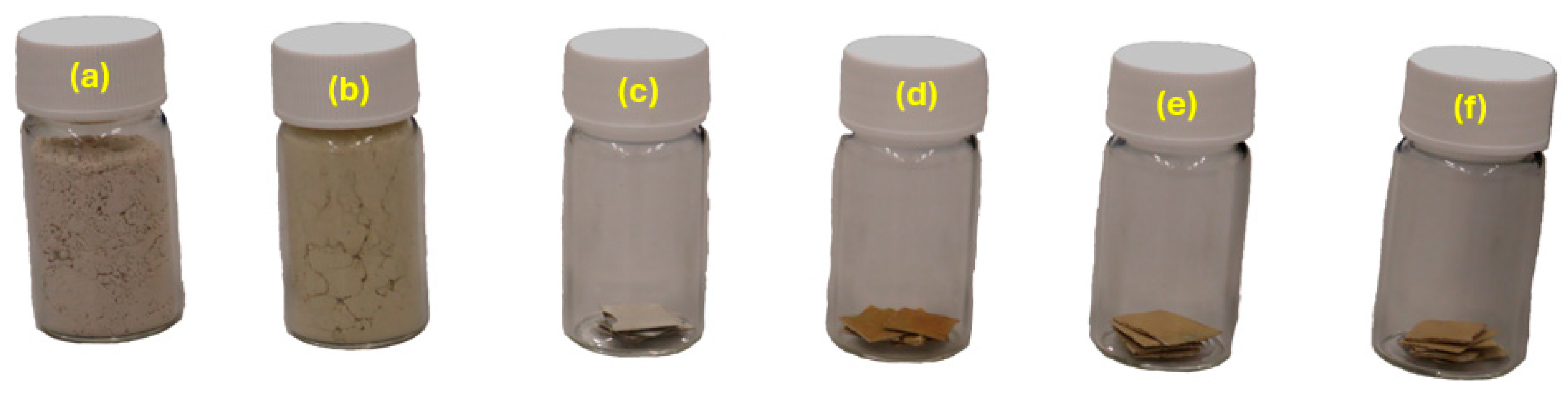
Figure 3 presents the Fourier transform infrared spectroscopy spectra of the coating constitutive nanopowders.
The infrared spectroscopy analysis of the nanopowders was carried out using a Nicolet 5700® FTIR spectrometer (Nicolet Instrument Corporation, Fitchburg, WI, USA) with the aid of a Smart ITR® ATR device (ThermoScientific, Waltham, MA, USA). The analyzed powders included the following:
(i)
Diatomite in the as-received state;
(ii)
Diatomite grafted with APTES and then fluorinated with PFOTS;
(iii)
Diatomite fluorinated with PFTOS and then grafted with APTES.
In the obtained spectra, it was possible to identify the band of the O-H stretching vibration of the silanol groups of APTES at 3379 cm−1. Also, the amine surface modification success of APTES can be confirmed by the band of the NH2 functional group deformation at 1616 cm−1. In the frequency range between 1300 cm−1 and 600 cm−1, we identified the following bands of interest:
(i)
CF2 functional group vibration at 696 cm−1;
(ii)
Si-O vibration at 754 cm−1;
(iii)
Si-O symmetric stretching vibration at 793 cm−1;
(iv)
Si-OH vibration at 908 cm−1;
(v)
Si-O-Si vibration at 1032 cm−1;
(vi)
Si-O in-plane stretching vibration at 1130 cm−1;
(vii)
C-C symmetric stretching vibration at 1159 cm−1;
(viii)
CF2 functional group symmetric stretching vibration at 1186 cm−1;
(ix)
CF2 functional group asymmetric vibration at 1227 cm−1.
In addition to almost overlapping with only negligible differences of the two FTIR spectra of the sililated diatomite, this indicated that in terms of the final composition of the powders, adding the fluorosilane (PFOTS) or, alternatively, the aminosilane (APTES) first made practically no difference.

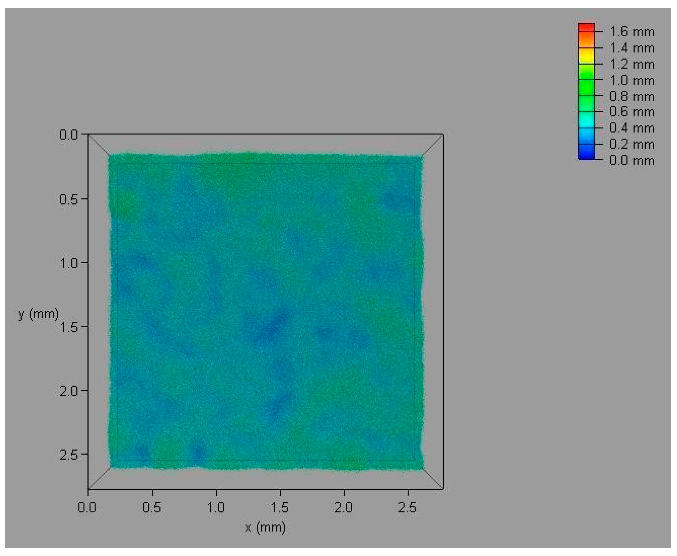
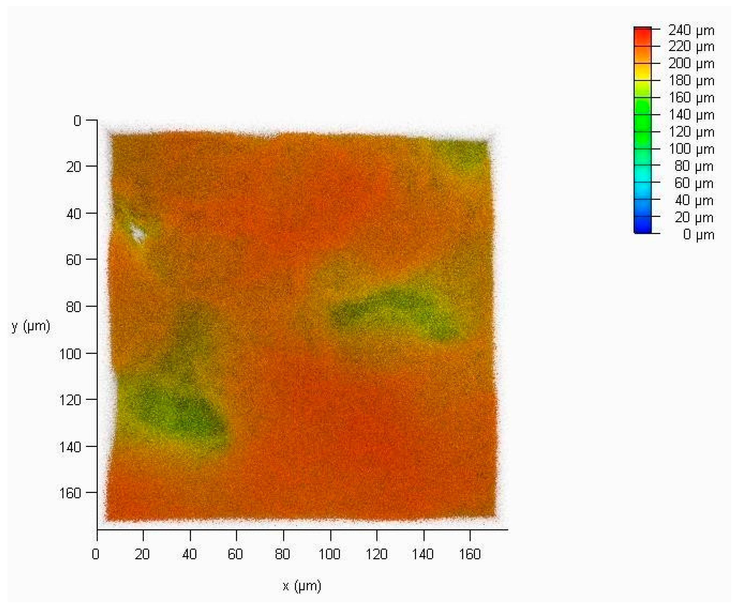
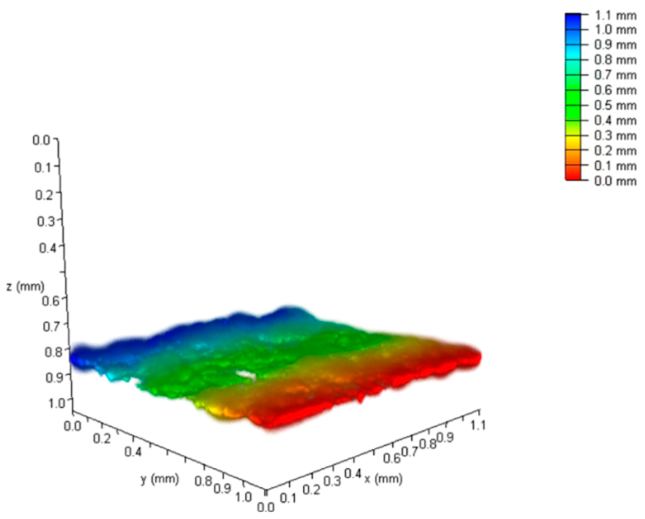
4.1.2. Laser Scanning Confocal Microscopy

A confocal microscope, Leica® TCS SP8 (Wetzlar, Germany), was employed to perform a topographic analysis of the surface of the coatings. Through the reflective mode, we conducted surface scanning on different planes with a pre-defined step. The three-dimensional image incorporates the sum of several images taken at diverse planes and surface heights. We used different objectives with distinct magnifications. Prior to the microscopic analysis, the characterized substrate/coating sets were immersed in five distinct aqueous solutions with different concentrations of rhodamine B fluorophore (rhodamine B, ≥95% purity HPLC, from Sigma-Aldrich®). The initial solution was obtained by dissolving 50 mg of rhodamine B in 80 mL of water-DD under continuous and vigorous stirring at ambient temperature. The desired concentration was achieved by diluting 20 mL of the initial solution in 80 mL of water-DD. The procedure was repeated with identical successive dilutions until five different concentrations were achieved. The samples were then immersed in the rhodamine–distilled water solution and maintained in the solution for different periods. The most effective was the 48 h duration. Figure 4 shows a substrate/coating sample after immersion for 48 h in rhodamine B.
Figure 5, Figure 6, Figure A1 and Figure A2 show the obtained laser scanning confocal microscopy imaging.
As can be seen in the different microscopic images, the obtained coatings with the same composition had average thicknesses varying from 100 µm to 800 µm. The lack of total uniformity visible in a major part of the images is due to the dip-coating method. Despite being easy, cost-effective, and requiring only inexpensive equipment, this coating production method requires a fully dispersed coating solution, and it is very difficult to obtain a totally uniform final coating. Nonetheless, if the coating is applied in small areas like the superhydrophobic regions of a biphilic surface better uniformity could be attained.

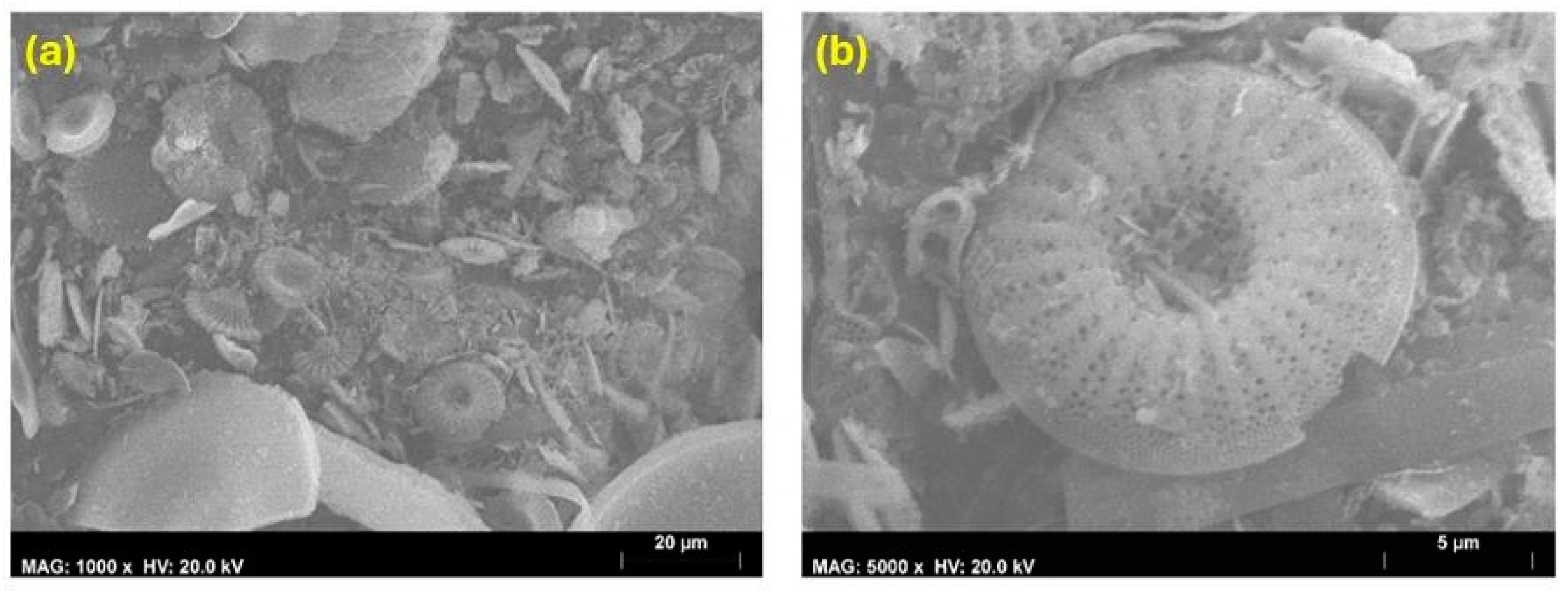
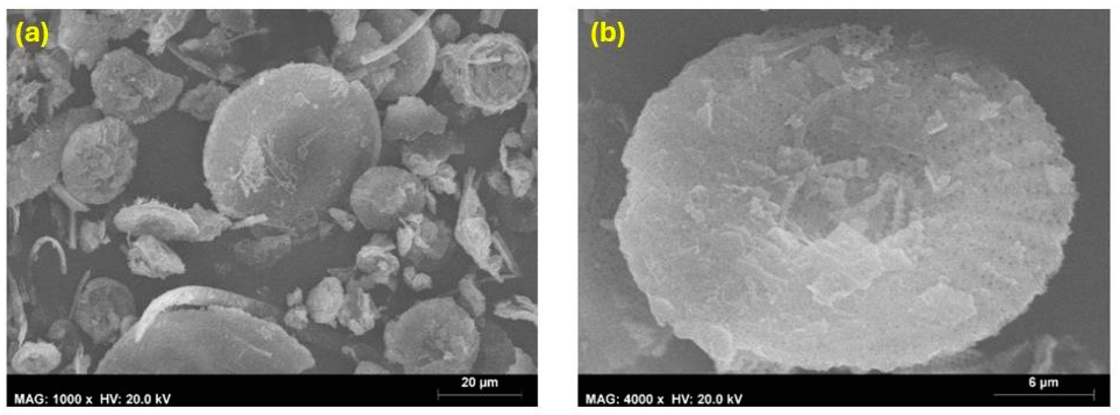
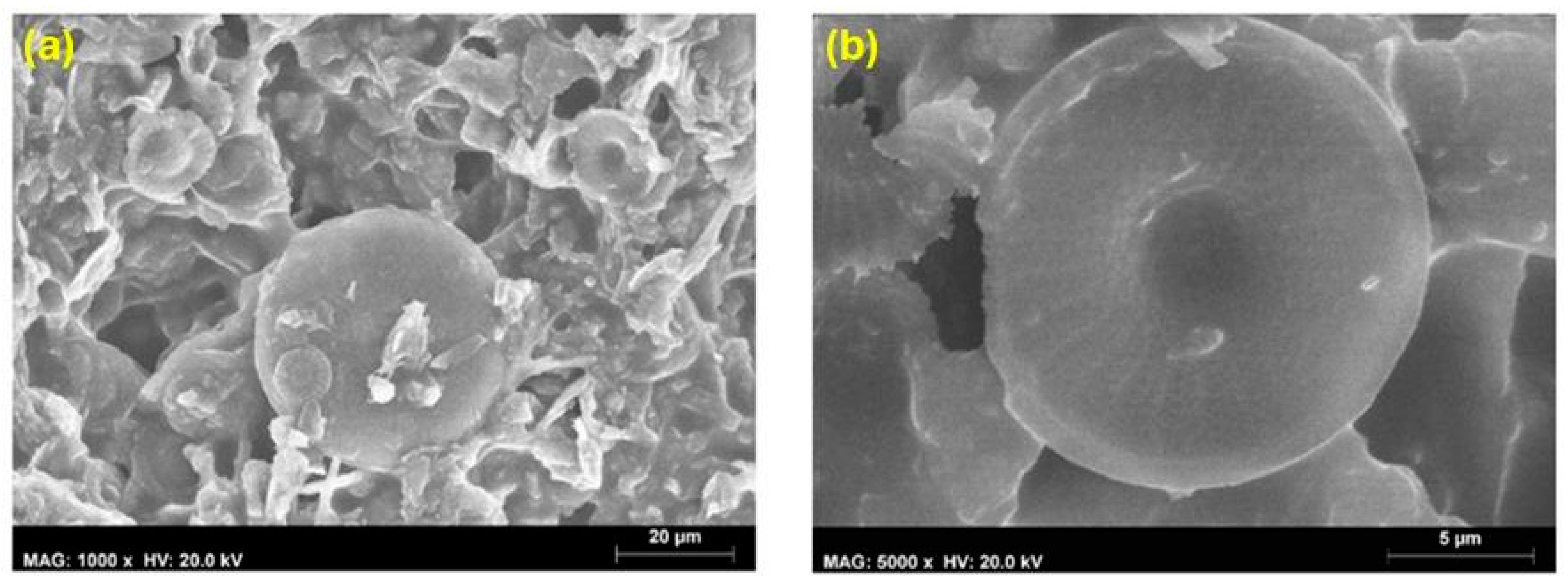
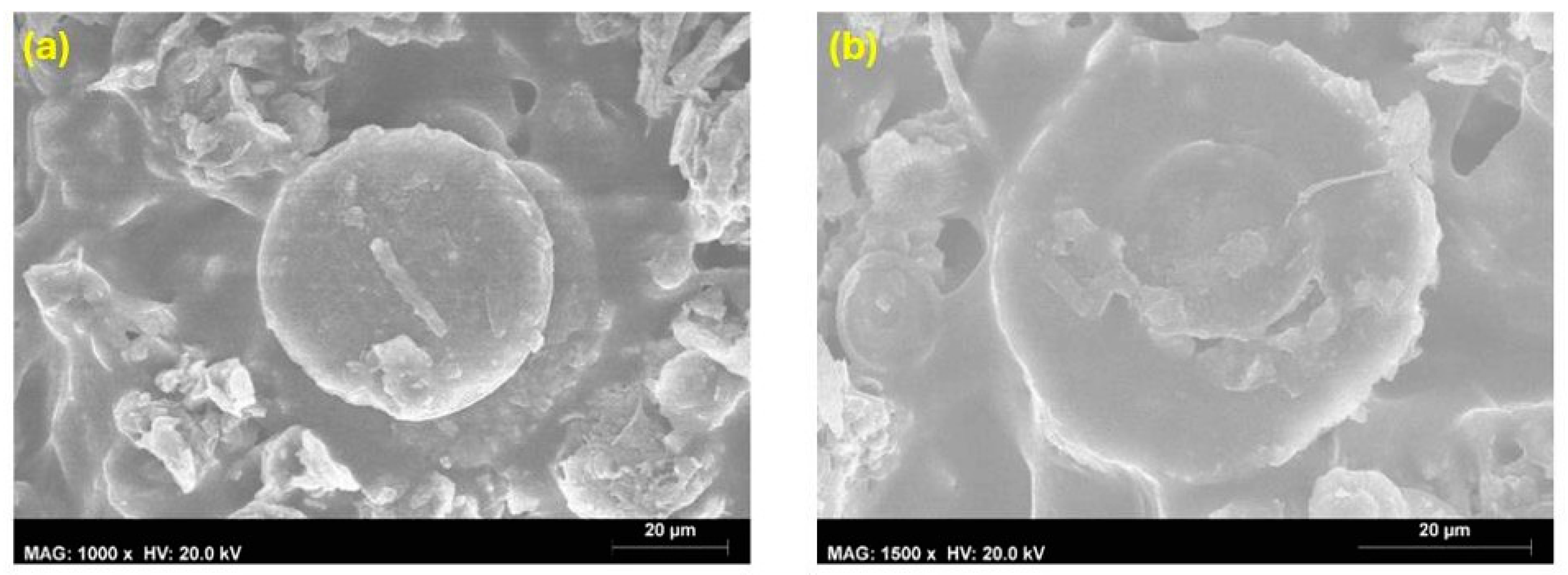
4.1.3. Scanning Electron Microscopy

At Microlab—Electron Microscopy Laboratory-IST (Lisboa, Portugal) facilities, six different samples were examined using scanning electron microscopy, as follows: untreated diatomite powder, treated diatomite powder with silanization, untreated diatomite–epoxy coating, 25% particle loading coating, 35% particle loading coating, and 45% particle loading coating. Figure 7 shows the analyzed samples. Prior to any observation, the samples were metalized using a sputter coater Sputter Coater Q150T-ES from Quorum Technologies® (Lewes, UK) with a gold and palladium electrical conductor thin film. After that, the samples were placed in a vacuum desiccator, Vacuum Desiccator 2251 from Pelco® (Fresno, CA, USA), for a pre-defined period.
Figure 8 and Figure 9 show the SEM images for the untreated diatomite powder and treated diatomite powder, respectively.
Untreated diatomite powder:
Figure 8. SEM micrographs of the untreated diatomite powder: (a) General view of the microstructure, (b) Detail of a diatomite disk.
Coatings 14 00805 g008
The SEM micrographs clearly display the porous character of the diatomite particles. This high-porosity degree promotes the formation of the enhanced specific surface area and roughness of the used particles. Also, the SEM micrographs of the untreated diatomite powder showed that the existing diatomite skeletons are mainly composed of disk-shaped particles with diameters between 10 and 20 µm. The rest of the particles in the analyzed sample were irregular or, alternatively, cylindrically shaped with diameters and lengths inferior to 20 µm. An important surface feature is the fact that a hierarchical roughness can be observed on the diatomite particles. As can be seen in Figure 9b, the captured diatomite particle possesses both nano- and micro-scale roughness, which is very useful for obtaining superhydrophobic surfaces resulting in macro- and mesopores.
Treated diatomite powder:
Figure 9. SEM micrographs of the treated diatomite powder: (a) General view of the microstructure, (b) Detail of a diatomite disk.
Coatings 14 00805 g009
The silanization procedure decreased the pore size distribution intensities, and this effect seems to provoke a decrease in the specific surface area of the treated diatomite powder. Increasing the fluorosilane PFOTS fraction of the diatomite may decrease the porosity degree and specific surface area of treated samples even further. This suggests that the fluorosilane either clogged or constricted some of the smaller pores of the diatomite particles. However, this effect did not strongly impact on the superhydrophobic nature of the treated particles. In essence, it should be stated that the addition of PFOTS reduced the specific surface area of the diatomite particles and their pore volumes. These effects do not affect the superhydrophobicity since the surface roughness from the diatomite particles is enough to induce superhydrophobicity. Figure 10 shows the micrographs corresponding to the untreated diatomite coating with only epoxy.
Untreated diatomite coating:
Figure 10. SEM micrographs of the DIATOMITE–EPOXY coating: (a) General view of the microstructure, (b) Detail of a diatomite disk.
Coatings 14 00805 g010
Figure 11, Figure 12 and Figure 13 show SEM images for the DIATOMITE–PFOTS–APTES–EPOXY coating with different particle loading percentages.
Twenty-five percent particle loading coating:
Figure 11. SEM micrographs of the DIATOMITE–PFOTS–APTES–EPOXY coating with 25% particle loading: (a) General view of the microstructure, (b) Detail of a diatomite disk.
Coatings 14 00805 g011
Thirty-five percent particle loading coating:
Figure 12. SEM micrographs of the DIATOMITE–PFOTS–APTES–EPOXY coating with 35% particle loading: (a) General view of the microstructure, (b) Detail of a diatomite disk.
Coatings 14 00805 g012
Forty-five percent particle loading coating:
Figure 13. SEM micrographs of the DIATOMITE–PFOTS–APTES–EPOXY coating with 45% particle loading: (a) General view of the microstructure, (b) Detail of a diatomite disk.
Coatings 14 00805 g013
There was no significant change in the surface morphology of the samples with particle loadings of treated particles superior to 0.25. At the studied particle loadings, the similarity in the superhydrophobic range is caused by the fact that the surface became covered with treated superhydrophobic particles. Only small fractions of the epoxy resin binder are visible. The incorporation of more diatomite particles into the surface covers the spacing between them and reduces the amount of air trapped beneath the particles. When the treated diatomite particles were mixed with the epoxy binder at a sufficient particle loading percentage, the diatomite migrated to the surface, producing a specific surface roughness. This was accompanied by the effect of the silanes, which provided a low-energy surface. The combination of the surface roughness and low-energy surface promoted an increase in the measured contact angles. With particle loadings above 0.25, the contact angles reached a plateau and remained at approximately 135–150°. In sum, the treatment of diatomite particles with silanes makes them somewhat incompatible with the epoxy resin binder, causing some of the particles to move to the air interface. The migration to the surface should depend on the concentration of particles and the viscosity of the binder, which is comparatively low in the case of the epoxy resin.

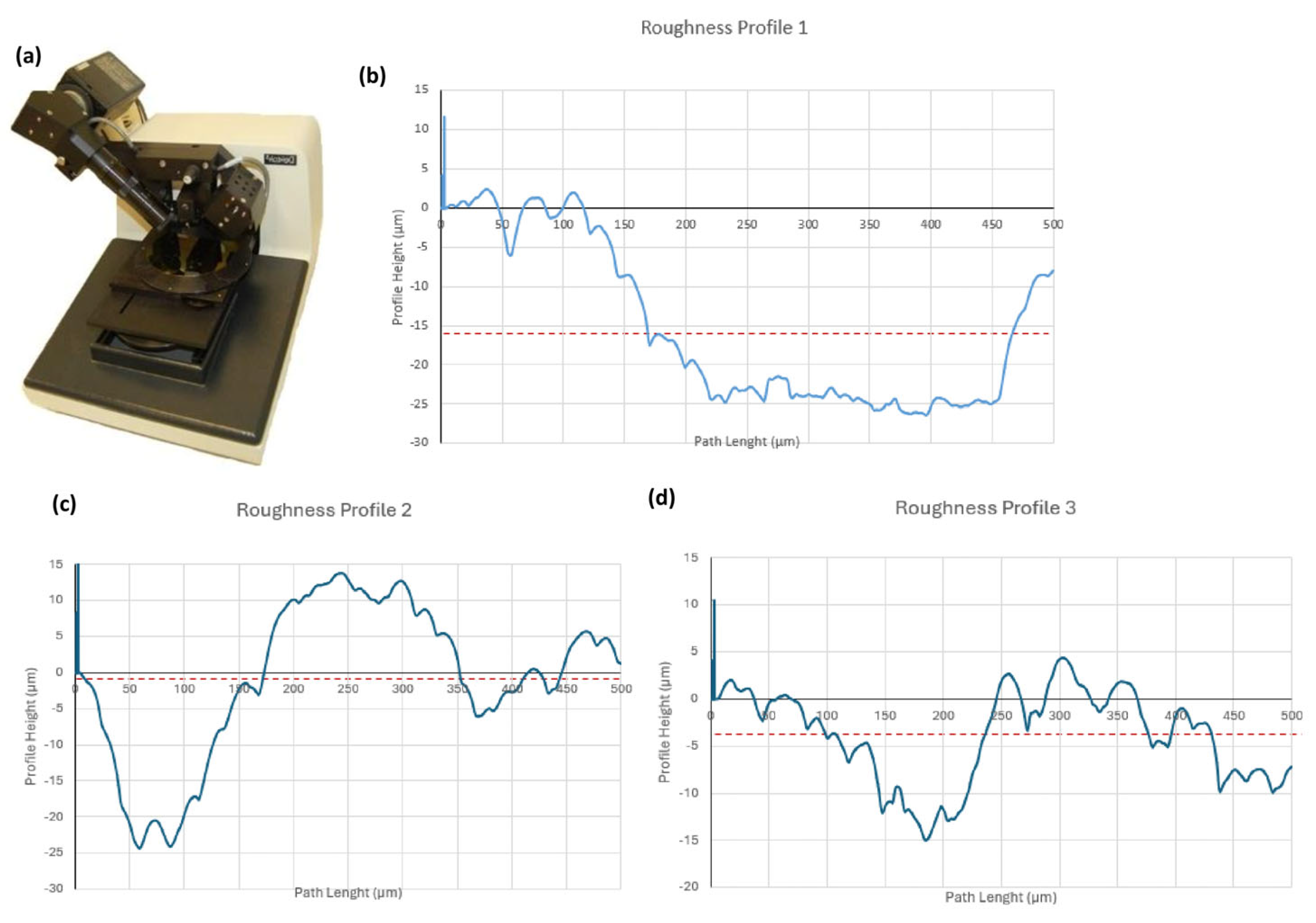
4.1.4. Roughness Measurement

The surface roughness analysis of the coatings was performed with the aid of a Dektak 3—Veeco profilometer (Veeco Instruments, New York, NY, USA) with a maximum vertical resolution of 200 Å. For that purpose, a diamond stylus was placed and dragged along the testing surfaces to obtain the surface roughness profiles of five substrate/coating sets. Figure 14 presents the obtained surface roughness profiles.
After obtaining the surface roughness profiles, they were processed to determine the values of the mean arithmetic roughness Ra and the mean peak-to-peak roughness Rz according to the DIN 4768 standard [24]. The corresponding values, together with the respective standard deviations, are summarized in Table 2. The stainless-steel substrate gave near-zero Ra and Rz values within the resolution of the equipment. Hence, the surface roughness of the substrate is taken to be negligible.

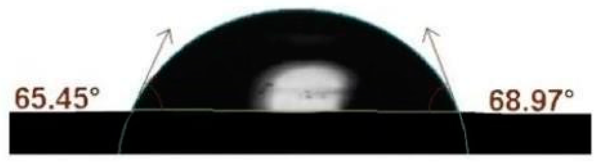
4.1.5. Contact Angle Measurement

The water contact angles of the coatings were measured with an optical tensiometer, Attension® Model Theta® (Biolin Scientific AB, Vastra Frolunda, Sweden), employing the sessile droplet method. The adjustment of the interface droplet/coating line was performed automatically. The acquired images were captured through a video camera and post-processed using the One Attension software version 4.1 according to the Young–Laplace model. The distilled water droplets were deposited in six different representative points of the coatings with the aid of a micropipette. The used droplet volume was nearly 5 µm. Finally, the obtained results were the left contact angle, right contact angle, and average contact angle. Figure 15 shows the optical tensiometer and the water contact angle measurement method. Figure 16 shows the main results of the water contact angle measurement. Figure 17 shows the water contact angle measurement for the stainless steel foil substrate. Table 3 summarizes the main results of the water contact angle measurement.
DE–PFOTS–APTES–PS:
This solution provided only a very weak adhesion of the polystyrene binder onto the stainless steel substrate, indicating that this binder was not the most adequate for this type of substrate. Therefore, such evidence inhibited any wettability evaluation through the water contact angle measurement for this technical solution/hypothesis.
DE–PFOTS with PS skeleton and EPOXY binder:
This solution provided only very little adhesion of the final coating on the entire stainless steel substrate. Therefore, this fact inhibited any wettability evaluation using a water contact angle measurement and any further processing/study of this solution/hypothesis.

4.1.6. Thermal Conductivity Measurement

For the thermal conductivity and other thermophysical properties of the coatings, three distinct samples were prepared with different particle loadings of the filler. For that purpose, the diatomite–APTES–PFOTS–epoxy solution was poured into PLA 3D printing molds and post-cured in an oven. Figure A3 presents the sample preparation procedure with the used mold, the solution poured in the mold, and the final measuring coating disk. After that, the samples were removed from the mold, and the resulting coating disks were used for thermal conductivity measurements using a hot disk thermal analyzer from Hot Disk®, as shown in Figure A4.
The main results of the thermal conductivity, thermal diffusivity, and specific heat are summarized in Table 4.

5. Durability Tests

Superhydrophobic surfaces can be evaluated through different durability assays, including mechanical, chemical, and water impact, among others. The mechanical robustness of superhydrophobic surfaces is a critical issue and has become a noticeable concern, particularly when dealing with heat transfer surfaces with a superhydrophobic nature. The micro-/nano-scaled hierarchical structures formed by the incorporating particles, as well as certain non-flexible polymeric binders, have been found to be highly sensitive to different mechanical stresses. The damage of the nanoparticles or the distortion of the binder may lead to an increased solid/liquid interfacial contact area and alterations in the surface chemistry. Such effects may result in the loss of the superhydrophobic character of the surface. The most followed route for effective durability is to make the developed surfaces withstand external mechanical stresses without altering their morphology and chemical composition too much. Also, the main eligible features related to the mechanical robustness assessment of the surfaces are the adhesion strength to the substrate, abrasion resistance, and dynamic liquid and solid impact resistance.

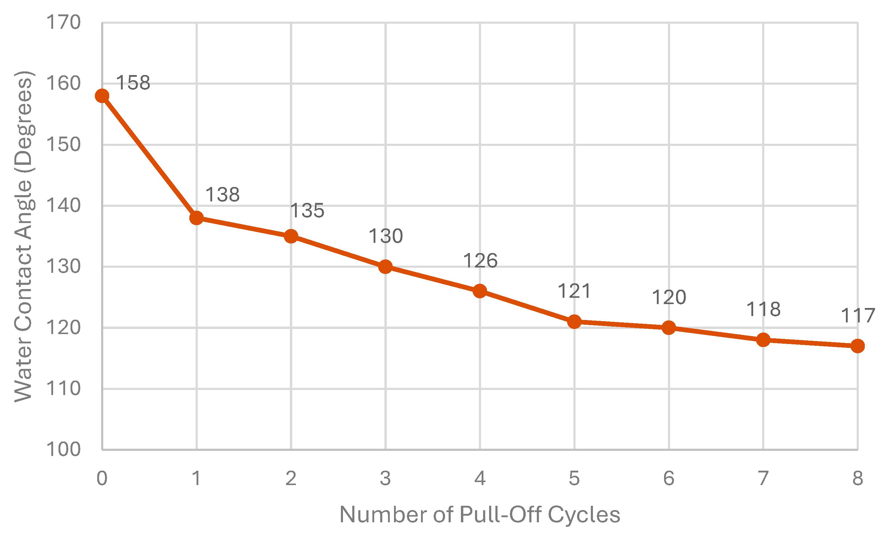
5.1. Adhesion Resistance Test (Peel-Off Test)

The adhesion resistance assay infers whether the superhydrophobic coating adheres securely to the substrate. This test is usually the first to be carried out for evaluating the durability of the coatings in general, given that an insufficient adhesion level will provoke the detachment of the coating under service. Also, the adhesion and coherence within the coating itself is also of importance, and the cohesive forces between the base material and the binder should also be investigated. The tape peeling test is a useful and straightforward way to remove constitutive material from a surface or coating, and it is normally employed to evaluate the adhesive strength of hydrophobic coatings that cover a wide range of different substrates. This test usually follows the following procedure:
  • A peeling tape is applied and carefully pressed down with a metal cylinder onto the surface to be tested to eliminate any air entrapment and to ensure uniform contact between the tape and testing coating;
  • The tape is peeled off from the surface vertically from one end, the after-peeled condition of the coating is evaluated, and it is observed whether the coating was completely removed or, alternatively, only partially detached;
  • The procedure of points one and two completes one peeling cycle, and after each cycle, the wettability of the coating should be characterized using a contact angle measurement.
It should be noted that the peeling tapes can be classified according to their own adhesion strength, which is defined against a reference substrate. A major part of the cases refers to a steel substrate, and the adhesion strength is expressed in Newtons per meter. Also, a higher adhesion strength factor can be translated into more severe damage to the testing coating. The adhesion test of the coating was performed based on the ASTM D 3359-02 standard [25] with the aid of a commercially available bonding tape with high adhesion to steel VHbB from 3M®. In the test, the tape was applied on top of the coating by rolling a massive steel cylinder weighing 2 Kg on the testing tape. The rolling procedure was completed whenever the tape was completely flat with no wrinkles and adherent. After 1 min of bonding, the tape was peeled off. The procedures of the application and peeling of the tape formed one cycle of the assay, and a new piece of tape was employed for each testing cycle. After each cycle, the water contact angle of the remaining coating was measured using optical tensiometry. Figure 18 schematically illustrates the adhesion resistance test procedure of the coating. Figure 19 presents the plot of the water contact angle vs. the number of pull-off cycles.

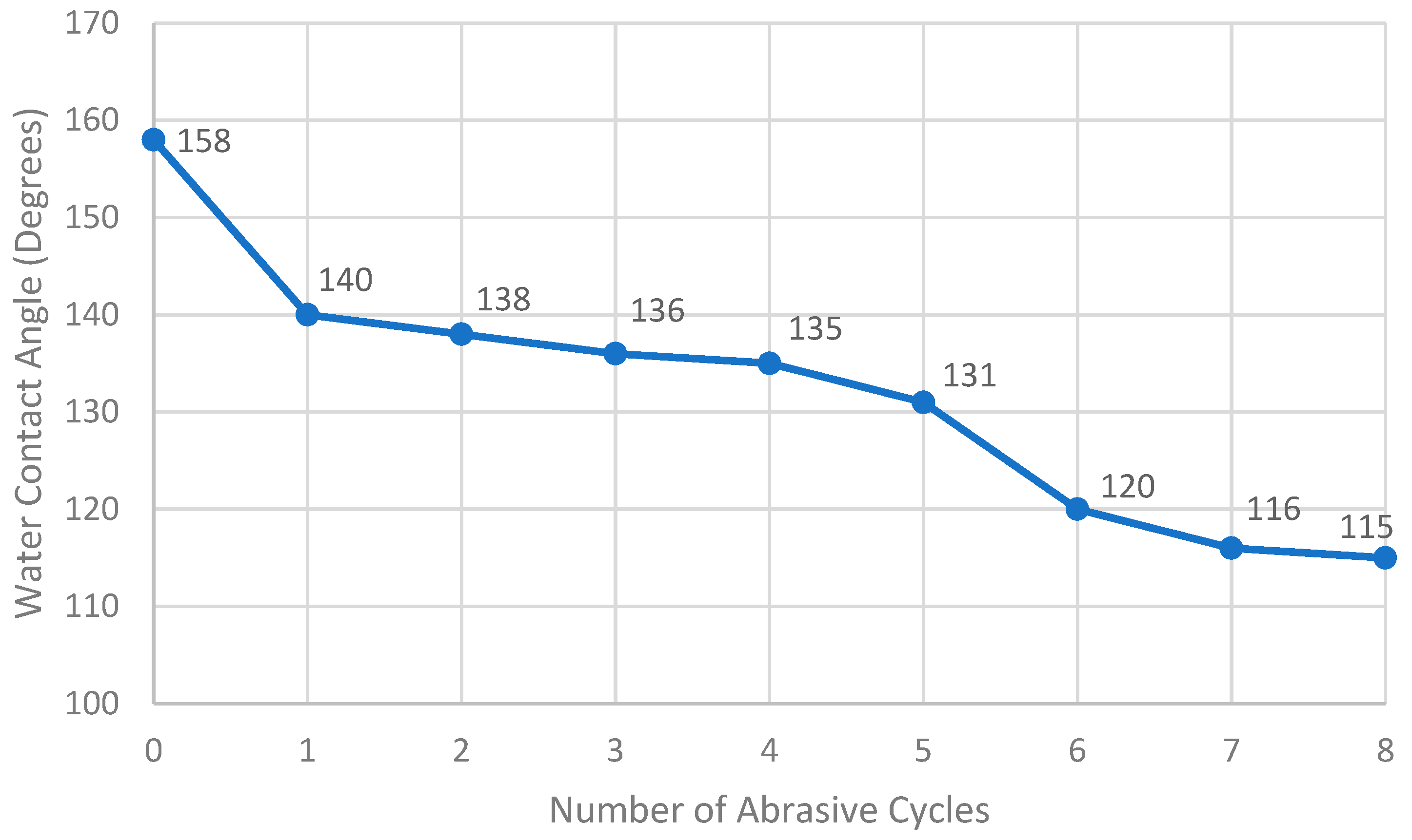
5.2. Abrasion Resistance Test

The abrasion resistance test of coatings can be performed by imposing a linear shear abrasive action across the surface. This wearing action is usually performed using an abrasive paper. The abrasive effect may result in surface modification and the loss of hydrophobicity. The abradant material can be sandpaper, PDMS, or rubber, and the load applied on the tested coating can be adjusted by selecting different block weights. In each cycle of the test, the set sample/weight will move along a pre-determined path across the abrasive paper. The fundamental features that should be evaluated with this test are the number of cycles until the loss of hydrophobicity and the total number of cycles that is required to physically remove the coating, exposing the substrate below it. This test allowed for the evaluation of the abrasion resistance and wettability of the coatings. The test itself was based on the ASTM D4060-19 [26] standard and consisted of applying a pressure of 2.5 kPa onto the coatings typical to the 180-grid silicon carbide abrasive paper. Then the coating was dragged across the abradant, taking the course of 10 cm in one direction with a pre-defined velocity of approximately 3 cm per second in such a way that all the coating extension was abraded. This procedure defined a test cycle. The cycles were repeated until a maximum of five cycles was reached. After each complete test, the integrity of the coatings was evaluated through a visual inspection, and the equilibrium water contact angle was determined using optical tensiometry. Table A1 summarizes the qualitative analysis of the coatings. Figure 20 schematically illustrates the abrasion resistance test procedure of the coating. Figure 21 presents the plot of the water contact angle vs. the number of abrasive cycles.

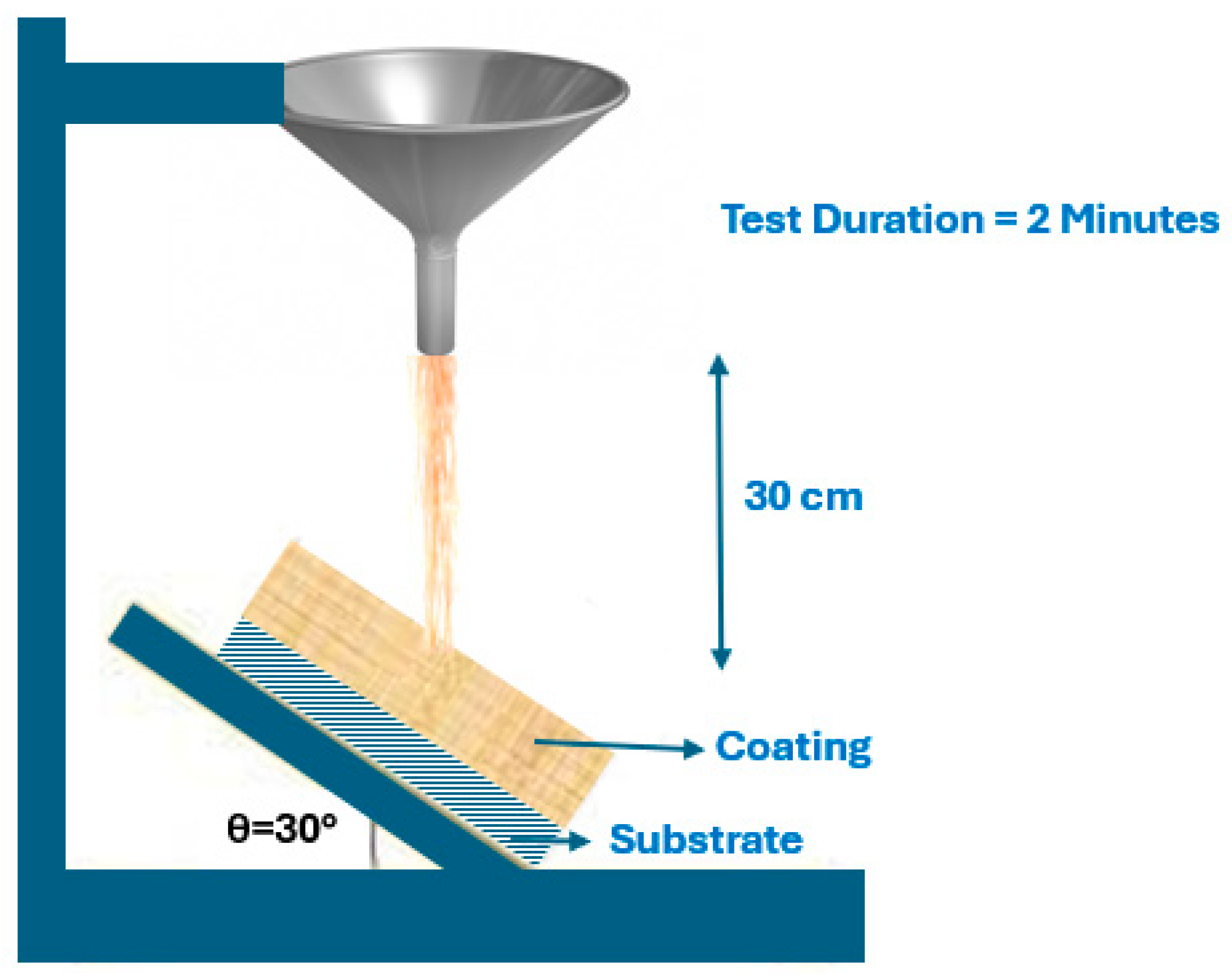
5.3. Solid Impact Resistance Test

The durability of the coatings can also be inferred under collision or impact with a solid. In such dynamic impact assays, the coatings are placed either horizontally or tilted at 45°. The morphology of the surface and the superhydrophobic nature may be considerably changed after the collision with solid particles. One of the most performed assays employs micro-sized grains of sand, or another alternative material, impacting the testing surface. The tilting of the coating averts the deposition of the solid grains after their impact and enables the rolling of the grains over the coating. The latter action generates an abradant effect that can be useful to evaluate the abrasion resistance of the coating. Moreover, the solid grains are weighed to a fixed mass, put in a glass hopper, and flow from there at a constant rate until they impact the surface. The hopper is positioned at a pre-defined height from the coating surface. The varying height of the glass container will alter the kinetic energy of the grains. Hence, an increased height will induce augmented kinetic energy, and consequently, increased damage is expected to occur on the testing coating. The solid impact resistance and abrasion test of the coating was performed based on the ASTM D968-22 [27] standard of the falling sand abrasive test, using 250 g of aluminum oxide grains that were dropped from a height of 30 cm onto the 30° tilted coating for two minutes. After being dropped and impacted on the testing coating, the aluminum oxide grains slid down over the coating surface, inducing an abrasive effect. This procedure represented one testing cycle, and the next one was carried out with a fresh portion of grains. After each cycle, the water contact angle of the tested coating was measured using optical tensiometry. All the tested samples passed the test. Figure 22 schematically illustrates the apparatus used for the solid impact resistance test.

5.4. Liquid Impact Resistance Test

The liquid impact test is a very suitable assay to evaluate the durability of hydrophobic surfaces. The operating liquid can be in the form of sprayed micro-sized droplets, regular-sized droplets, or liquid jets. This test can mimic the contact of the surface with the heat transfer fluids that serve in thermal management systems and devices. The employed free-fall liquid impact apparatus is usually like the solid–liquid impact apparatus, with the only difference being the liquid dispenser instead of the container of the solid particles. By increasing the pressure of the ejected liquid, the testing action of the assay will impart more damage to the testing surface. More specifically, in the free-fall liquid impact test the nano-micro hierarchical structure of the coating can be deteriorated by the continuous impact of the droplets, and in the liquid jet test, the spraying nozzle is replaced with a high-pressure jetting nozzle, usually producing even greater damage to the surface. The main parameters to set are the liquid jet velocity and diameter, the distance between the jet and the sample coating, and the tilting angle of the support of the coating. The liquid jet impacting the coating generates maximum pressure in a small area, which is very demanding from the coating robustness standpoint. In some cases, the hydrophobic nature of the coating remains unaltered after the initial impact of the liquid droplets or jet, but it gradually loses its hydrophobicity because of a Cassie-to-Wenzel wetting transition. The liquid penetration of the hierarchical surface features of the hydrophobic coating is expected to happen after consecutive tests. This penetration increases with the increasing size of the liquid droplet, impact velocity, and pressure. This test enabled the evaluation of the durability and wettability of the coatings when submitted to the action of a water jet. The test apparatus scheme is presented in Figure 23. The substrate/coatings sets were positioned at a 45-degree angle under the water jet at a pre-defined pressure. The water outlet was placed at a height of 5 cm from the testing coatings. The coatings were under the water jet for 10 min and under different pressures of 10 and 100 kPa. After each test, the integrity of the coating was inferred through a visual inspection, and the water contact angle was measured using optical tensiometry. Table A2 summarizes the qualitative analysis of the coatings.

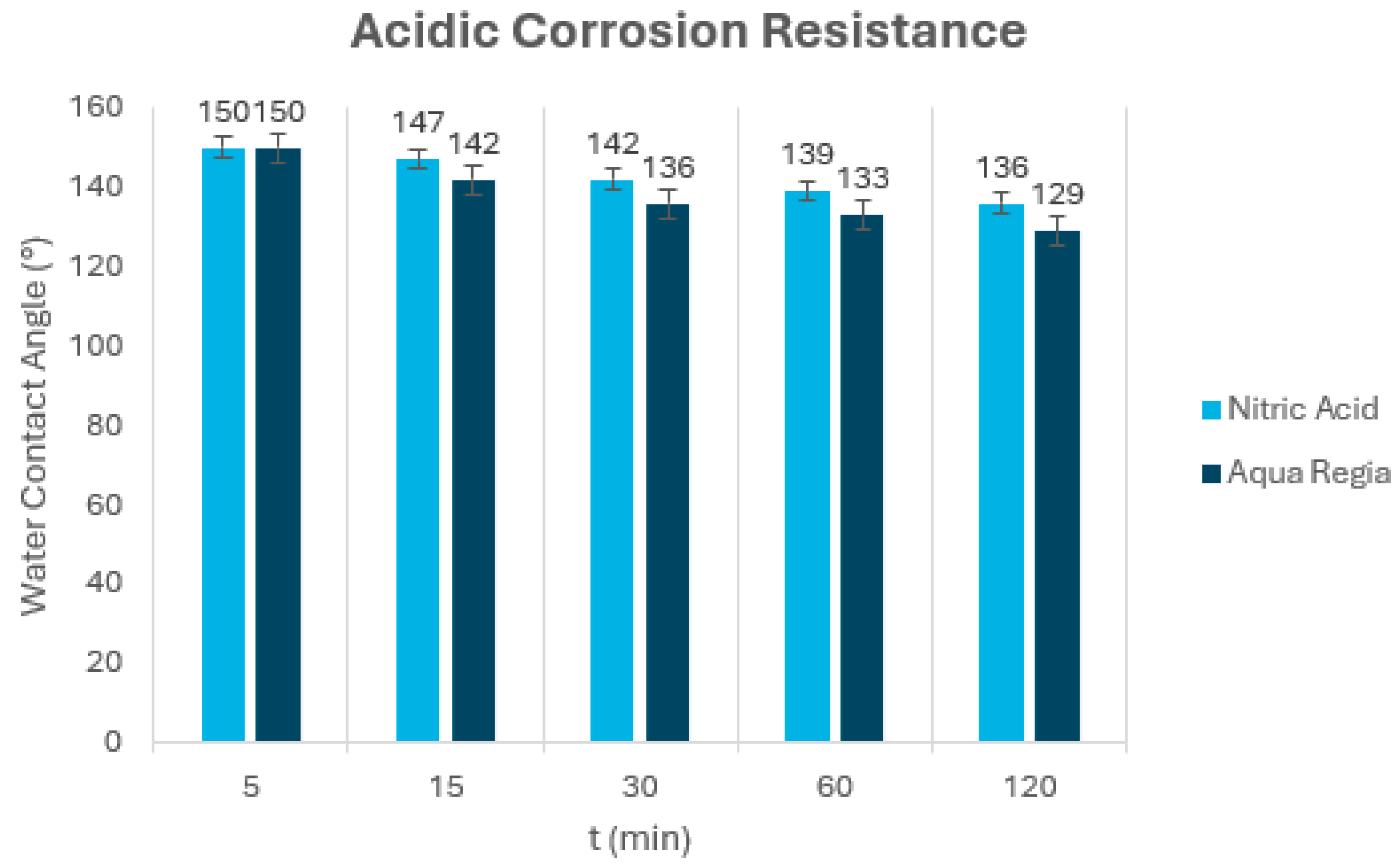
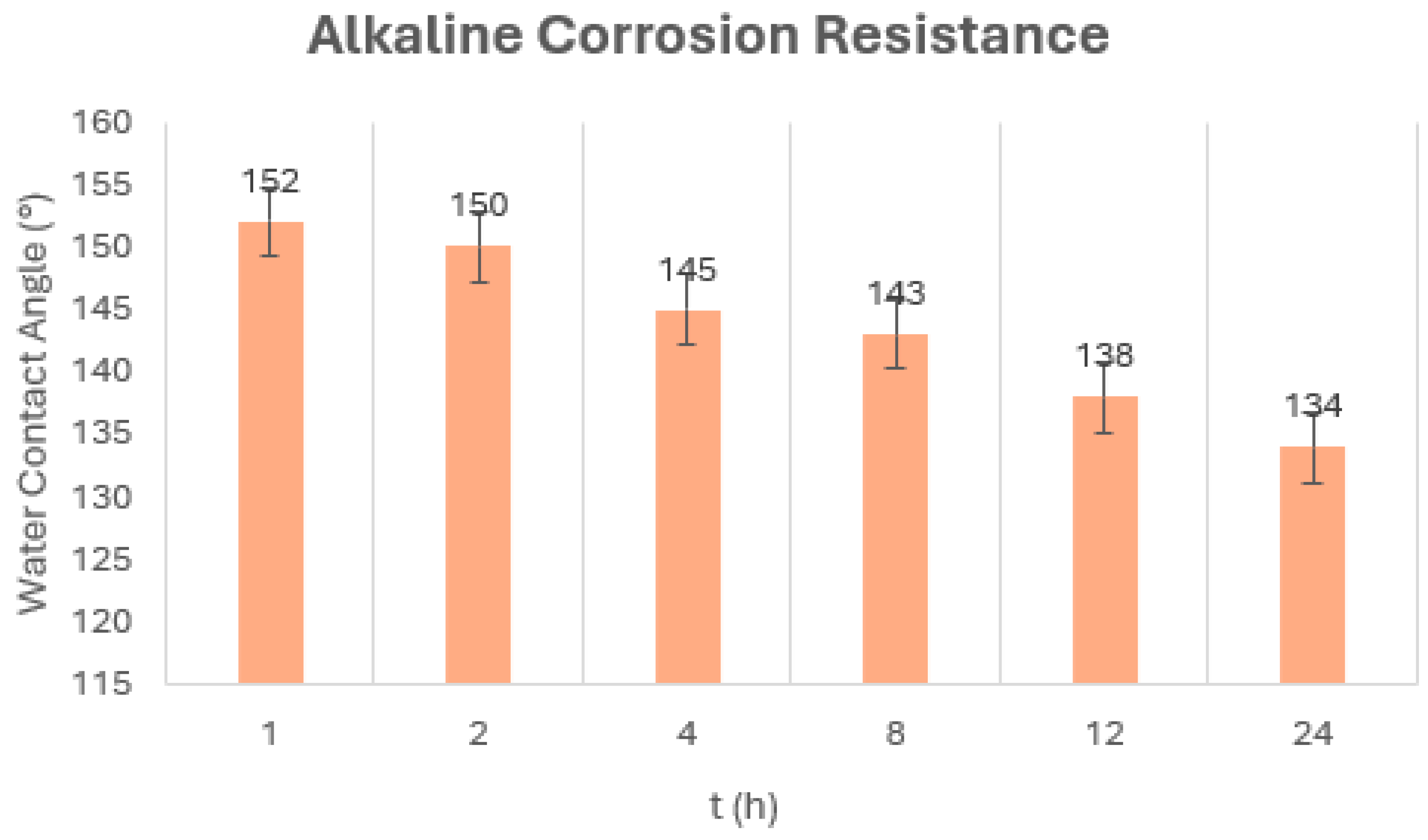
5.5. Corrosion Resistance Test

Chemical corrosion can cause the loss of superhydrophobicity due to the decomposition of the low-surface energy materials. This must be considered when superhydrophobic coatings are designed for practical applications. Researchers have begun to evaluate the corrosion resistance of superhydrophobic coatings and have prepared anticorrosive superhydrophobic coatings for specific practical applications. However, there are currently no well-established standard methods for evaluating the corrosion resistance of superhydrophobic surfaces. The most common approach to address the chemical corrosion resistance of superhydrophobic coatings is to immerse them in strong acids, strong alkalis, seawater, or NaCl solutions and to take them out of the corrosive solutions and evaluate their wettability using periodic contact angle measurement. To conduct the corrosion resistance tests, the stainless-steel foil/coating sets were immersed in acidic and alkaline solutions. We used a concentrated nitric acid solution or, alternatively, a 70% acid nitric solution with a pH equal to 3, a 1M alkaline sodium hydroxide solution, and aqua regia, a mixture of hydrochloric acid and nitric acid in a 3:1 volume ratio. After being immersed for 5, 15, 30, 60, and 120 min, the sets were rinsed with distilled water and air dried, and the equilibrium water contact angle of the coatings was measured using optical tensiometry. The coatings remained hydrophobic even after being immersed in aqua regia for 120 min. We found that the contact angle degraded gradually over the immersion time, and finally, droplets were seen to be pinning on the surface after two hours, indicating the loss of surface superhydrophobicity. The inherent chemical inertness of the selected coating constituents provided good chemical resistance. Figure 24 presents the chart of the water contact angle against the immersion time for the nitric acid and aqua regia. Figure 25 presents the chart of the water contact angle against the immersion time for sodium hydroxide.

5.6. Air Durability Test

We also tested the air exposure durability of the coatings at room temperature. In this sense, after one month of air exposure and without any special protection, the integrity of the coatings was inferred, and the water contact angle was measured using optical tensiometry. We observed no significant changes in the integrity of the coatings, or the water contact angles, indicating improved durability when exposed to air at room temperature.

5.7. Water Durability Test

This test enabled the evaluation of the durability of the coatings when immersed in water. The different substrate/coating sets were immersed in distilled water at room temperature and boiling temperature for 24, 48, 96, 192, 384, and 762 h. After each test, we carried out a qualitative visual inspection of the integrity of the coatings in terms of general aspect, color, hardness, thickness, wear, and eventual surface defects. The water contact angle was also measured using optical tensiometry after each test. Table A3 and Table A4 summarize the qualitative analysis for the different coatings after each test. There were no considerable changes in the water contact angle after each test. The water boiling resistance test was conducted in the in-house developed pool boiling equipment in the IN+-IST-Lisbon facilities. Indeed, it was a pool boiling experiment of the superhydrophobic coating, but without capturing the bubble dynamics and associated thermographic phenomena. Figure 26 and Figure A5 present a general view of the pool boiling equipment and a view of the pool boiling chamber and condenser sections, in which the water boiling resistance test was carried out.
The water reservoir was coupled with a pressure-measuring monometer and a thermocouple for temperature measuring. The pressure was kept at 1 bar. The chamber has an internal heating coil and a heating cartridge regulated by a PID controller, which turns the heating cartridge resistance on when the temperature measured by the thermocouple reaches the pre-defined value and turns it off when the temperature of the operating fluid is below that value. The boiling chamber also has two internal type K thermocouples for monitoring the temperature of the working fluid in different areas. One of the thermocouples measured the saturation temperature and was positioned near the coating sample. The other thermocouple was positioned a little farther from the boiling surface and was connected to the PID controller. Also, a pressure transducer from Omega Dyne® (Sunbury, OH, USA) connected to a dedicated DC power supply was positioned on top of the boiling chamber. Both thermocouples had a precision of 1 °C, whereas the pressure transducer had 1.6 mbar of precision. The thermocouples monitoring the operating fluid and heating surface temperatures and the pressure transducer were connected to a DT9829 DAQ board from Data Translation® (Marlborough, MA, USA), which in turn, was connected to a PC. The signals of pressure and temperature were acquired and recorded in the QuickDAQ® acquisition software version 3.7.0.46. The stainless steel base of the boiling chamber is shown in Figure A6. A copper cable connected each power connector to a small block of steel, which was welded to the testing surface. The test chamber was connected to the main reservoir, which also included a connection for the fluid outflow that is open after each pool boiling experiment. To retain the atmospheric working conditions, a steam condenser was installed on top of the boiling chamber. The generated steam in the pool boiling chamber goes upward to the condenser, and the liquid condensate goes downward back to the boiling chamber. The piping of the condenser was complete, with the tube connected to the condensate reservoir. The initial section of the tube was covered with an isolating sleeve to prevent the condensation of the vapor phase. Prior to any experiment, it was necessary to ensure that the operating fluid—considered as distilled water in this description—had the minimum non-condensable gases to attain a maximized degasification process. Hence, the distilled water was heated up to its point of ebullition and kept at a pressure of 1 bar for one hour. After that, the pressure was released, adjusted nearly to the atmospheric pressure, and kept there for one hour. Then the heating resistances were turned on to initiate the heating of the boiling chamber. At this point, the QuickDAQ® software version 3.7.0.46 was launched to monitor the working temperature and pressure. The distilled water started to flow into the test chamber. When the pool boiling test chamber was filled, the temperature of the water decreased by nearly 20 °C, and consequently, it needed to be reheated. To reheat the water and keep it at 100 °C, the internal resistances, PID controller, and power source for the heating coil were turned on. Table A3 and Table A4 show the qualitative analysis for the coatings after the water durability test in room conditions and boiling, respectively. Figure 27 shows the DE–PFOTS–APTES–EPOXY coating before and after immersion in boiling water for 192 h. We observed a contact angle reduction and changes in the aspect and color after the referred immersion.

5.8. Aging Durability Test

The aging durability test enabled the evaluation of the durability and wettability of the coatings. It consisted of the immersion of the substrate/coating sets for 120 h in an acetic acid solution with a pH equal to 3 to infer the resistance to weak acids. The sets were also emerged for the same period in a sodium hydroxide solution with a pH equal to 13 to evaluate the alkaline resistance of the sets. After immersion, the integrity of the coatings was evaluated through a visual inspection, and the water contact angle was determined using optical tensiometry. Table A5 summarizes the qualitative analysis of the different coatings after each test. There were no significant changes in the water contact angle after each test.

6. Conclusions

The main concluding remarks of the current experimental study are discussed in the following points:
  • The water contact angle measurement gave relatively standard deviations from point to point. This was mainly due to the surface heterogeneities caused by the different surface roughness, thickness, porosity, and topographical features of the six measuring spots across the coatings;
  • The dip-coating methodology has some limitations, such as the lack of total uniformity of the coatings if it is not subjected to a proper control. Hence, this method may impart non-uniform spreading of the coating particles, which may negatively influence the consistency of the experimental results;
  • Since the nanopowders and nanomaterials commonly exhibit an agglomerating trend, special care should be given to the preparation of the coating solutions, always attempting to obtain the most uniform dispersion of the nanopowders in the solvents. Otherwise, the coating solution may result in the formation of local agglomerates and surface heterogeneities when applied to the substrate, whatever the coating method;
  • However, in terms of scalability, all the referred issues are possible to mitigate, or even eliminate, in large-scale industrial production with ameliorated and rapid coating fabrication methods;
  • The solutions with better wettability performance that obtained average contact angles superior to 135° (considered as quasi-superhydrophobic or even superhydrophobic by some authors) were DE–APTES–EPOXY, two-layer DE–PFOTS–EPOXY, and DE–PFOTS–APTES–EPOXY;
  • It appears that the overlap of one or more coating layers did not entail any considerable wettability improvement. The superposition of coating layers even deteriorated the wettability measured for only one applied coating layer, as in the DE–APTES–EPOXY case;
  • None of the coating alternatives presented superior robustness and durability characteristics in all the tested parameters according to the performed resistance assays. Nonetheless, the conducted qualitative analysis gave strong indications to conclude that the solutions with better wettability performance in the superhydrophobicity near range were the ones with better durability;
  • Even considering the most performant coating formulations, these had only satisfactory performance in the robustness and durability tests, namely, in the more exigent ones like the abrasion resistance test;
  • Despite the non-ideal results, the characterization and robustness test results of the coatings indicate at least satisfactory behavior under pool boiling conditions in the form of biphilic boiling surfaces;
  • In further research, it is recommended to prepare biphilic boiling surfaces with different configurations of the developed coating of the superhydrophobic regions and test them under pool boiling conditions with the capture of high-speed images of the bubble dynamics and infrared thermographic images of the associated thermal phenomena.

Author Contributions

Conceptualization, J.P. and R.S.; methodology, J.P. and A.M. (Ana Moita); software, A.M. (Ana Moita); validation, A.M. (Ana Moita) and A.M. (António Moreira); formal analysis, A.M. (Ana Moita); investigation, J.P. and R.S.; resources, A.M. (António Moreira); data curation, J.P. and R.S.; writing—original draft preparation, J.P. and R.S.; writing—review and editing, J.P. and R.S.; supervision, A.M. (Ana Moita) and A.M. (António Moreira); project administration, A.M. (António Moreira); funding acquisition, A.M. (António Moreira). All authors have read and agreed to the published version of the manuscript.

Funding

The authors are grateful to the Fundação para a Ciência e a Tecnologia (FCT), Avenida D. Carlos I, 126, 1249-074 Lisboa, Portugal, for partially financing the project “Estratégias interfaciais de arrefecimento para tecnologias de conversão com elevadas potências de dissipação”, Ref. PTDC/EMETED/7801/2020, António Luís Nobre Moreira, Associação do Instituto Superior Técnico para a Investigação e o Desenvolvimento (IST-ID). José Pereira also acknowledges FCT for his PhD fellowship ref. 2021.05830.BD doi: 10.54499/2021.05830.BD. The authors are also grateful for FCT funding through 2022.03151.PTD and LA/P/0083/2020 IN + -IST-ID. A.S. Moita acknowledges Fundação para a Ciência e Tecnologia from the support doi: 10.54499/CEECINST/00043/2021/CP2797/CT0005.

Institutional Review Board Statement

Not applicable.

Informed Consent Statement

Not applicable.

Data Availability Statement

Data is contained within the article.

Conflicts of Interest

The authors declare no conflicts of interest.

Nomenclature

CpSpecific heat capacity [J·Kg−1·K−1]
kThermal conductivity [Wm−1·K−1]
DThermal diffusivity [m2/s]
µViscosity of suspensions [Pa·s]
RaMean arithmetic rugosity [µm]
RzMean peak-to-peak rugosity [µm]
TsSurface temperature (K)
TsatSaturation temperature of the liquid (K)

Appendix A

Table A1. Qualitative analysis for the coatings after the abrasion resistance test. √—no considerable changes in the integrity and contact angle, ×—degradation and/or contact angle reduction.
Coating1 Cycle2 Cycles3 Cycles4 Cycles5 Cycles
DE–APTES–EPOXY××××
DE–APTES–EPOXY
Two Layers
×××
DE–APTES–EPOXY
Three Layers
×××
DE–PFOTS–EPOXY×××
DE–PFOTS–EPOXY
Two Layers
××
DE–PFOTS–APTES– EPOXY×××
DE–PFOTS–APTES– EPOXY
Two Layers
××
Table A2. Qualitative analysis for the coatings after the water jet impact resistance test. √—no considerable changes in the integrity and contact angle, ×—degradation and/or contact angle reduction.
Coating10 kPa100 kPa
DE–APTES–EPOXY×
DE–APTES–EPOXY
Two Layers
DE–APTES–EPOXY
Three Layers
DE–PFOTS–EPOXY×
DE–PFOTS–EPOXY
Two Layers
×
DE–PFOTS–EPOXY
Three Layers
×
DE–PFOTS–APTES– EPOXY
Two Layers
×
Table A3. Qualitative analysis for the coatings after the water durability test. √—no considerable changes in the integrity and contact angle, ×—degradation and/or contact angle reduction.
Coating24 h48 h96 h192 h384 h762 h
DE–APTES–EPOXY××
DE–APTES–EPOXY
Two Layers
DE–APTES–EPOXY
Three Layers
DE–PFOTS–EPOXY××
DE–PFOTS–EPOXY
Two layers
DE–PFOTS–APTES– EPOXY××
DE–PFOTS–APTES– EPOXY
Two Layers
Table A4. Qualitative analysis for the coatings after the boiling water durability test. √—no considerable changes in the integrity and contact angle, ×—degradation and/or contact angle reduction.
Coating24 h48 h96 h192 h384 h762 h
DE–APTES–EPOXY×××
DE–APTES–EPOXY
Two Layers
×
DE–APTES–EPOXY
Three Layers
×
DE–PFOTS–EPOXY×××
DE–PFOTS–EPOXY
Two layers
×
DE–PFOTS–APTES– EPOXY×××
DE–PFOTS–APTES– EPOXY
Two Layers
×
Table A5. Qualitative analysis for the coatings after the aging durability test. √—no considerable changes in the integrity and contact angle, ×—degradation and/or contact angle reduction.
CoatingAcetic Acid, pH = 3Sodium Hydroxide, pH = 13
DE–APTES–EPOXY××
DE–APTES–EPOXY
Two Layers
×
DE–APTES–EPOXY
Three Layers
DE–PFOTS–EPOXY×
DE–PFOTS–EPOXY
Two layers
×
DE–PFOTS–APTES– EPOXY×
DE–PFOTS–APTES– EPOXY
Two Layers
×

Appendix B

Figure A1. Top view of the coatings at 5× magnification.
Coatings 14 00805 g0a1
Figure A2. Top view of the coatings at 63× magnification.
Coatings 14 00805 g0a2
Figure A3. Thermal conductivity measuring sample preparation: (a) 3D printing mold, (b) diatomite–APTES–PFOTS–epoxy solution poured in the mold, and (c) post-cured coating disk for thermal conductivity measurement.
Coatings 14 00805 g0a3
Figure A4. Thermal conductivity hot disk thermal analyzer: (a) general view of the apparatus, (b) front view of the hot disk thermal analyzer, (c) sample holder, and (d) sensor.
Coatings 14 00805 g0a4
Figure A5. View of the pool boiling chamber and condenser sections.
Coatings 14 00805 g0a5
Figure A6. Stainless steel base of the pool boiling chamber (a) upper side and (b) underside.
Coatings 14 00805 g0a6

References

  1. Yuan, X.; Du, Y.; Fei, G.; Yang, R.; Wang, C.; Xu, Q.; Li, C. Experimental study on developing in-situ hierarchical micro/nanocrystals for improved capillary wicking. Microfluid. Nanofluid. 2023, 27, 31. [Google Scholar] [CrossRef]
  2. Vrieling, E.G.; Beelen, T.P.M.; van Santen, R.A.; Gieskes, W.W.C. Diatom silicon biomineralization as an inspirational source of new approaches to silica production. J. Biotechnol. 1999, 70, 39–51. [Google Scholar] [CrossRef]
  3. Gulturk, E.A.; Guden, M.; Tasdemirci, A. Calcined and natural frustules filled epoxy matrices: The effect of volume fraction on the tensile and compression behavior. Compos. B Eng. 2013, 44, 491–500. [Google Scholar] [CrossRef]
  4. Nine, M.J.; Cole, M.A.; Johnson, L.; Tran, D.N.H.; Losic, D. Robust Superhydrophobic Graphene-Based Composite Coatings with Self-Cleaning and Corrosion Barrier Properties. ACS Appl. Mater. Interfaces 2015, 7, 28482–28493. [Google Scholar] [CrossRef]
  5. Yuan, P.; Liu, D.; Tan, D.-Y.; Liu, K.-K.; Yu, H.-G.; Zhong, Y.-H.; Yuan, A.-H.; Yu, W.-B.; He, H.-P. Surface silylation of mesoporous/macroporous diatomite (diatomaceous earth) and its function in Cu(II) adsorption: The effects of heating pretreatment. Microporous Mesoporous Mater. 2013, 170, 9–19. [Google Scholar] [CrossRef]
  6. Vasani, R.B.; Losic, D.; Cavallaro, A.; Voelcker, N.H. Fabrication of stimulus-responsive diatom biosilica microcapsules for antibiotic drug delivery. J. Mater. Chem. B 2015, 3, 4325–4329. [Google Scholar] [CrossRef] [PubMed]
  7. Shibuichi, S.; Yamamoto, T.; Onda, T.; Tsujii, K. Super Water- and Oil-Repellent Surfaces Resulting from Fractal Structure. J. Colloid Interface Sci. 1998, 208, 287–294. [Google Scholar] [CrossRef] [PubMed]
  8. Li, L.; Roethel, S.; Breedveld, V.; Hess, D.W. Creation of low hysteresis superhydrophobic paper by deposition of hydrophilic diamond-like carbon films. Cellulose 2013, 20, 3219–3226. [Google Scholar] [CrossRef]
  9. Nystrom, D.; Lindqvist, J.; Ostmark, E.; Hult, A.; Malmstrom, E. Superhydrophobic bio-fibre surfaces via tailored grafting architecture. Chem. Commun. 2006, 34, 3594–3596. [Google Scholar] [CrossRef]
  10. Chen, W.; Fadeev, A.Y.; Hsieh, M.C.; Oner, D.; Youngblood, J.; McCarthy, T. Ultrahydrophobic and Ultralyophobic Surfaces: Some Comments and Examples. Langmuir 1999, 15, 3395–3399. [Google Scholar] [CrossRef]
  11. Callies, M.; Chen, Y.; Marty, F.; Pépin, A.; Quére, D. Microfabricated textured surfaces for super-hydrophobicity investigations. Microelectron. Eng. 2005, 78–79, 100–105. [Google Scholar] [CrossRef]
  12. Shirtcliffe, N.J.; McHale, G.; Newton, M.I.; Perry, C.C.; Roach, P. Porous materials show superhydrophobic to superhydrophilic switching. Chem. Commun. 2005, 25, 3135–3137. [Google Scholar] [CrossRef]
  13. Puretskiy, N.; Chanda, J.; Stoychev, G.; Synytska, A.; Ionov, L. Anti-Icing Superhydrophobic Surfaces Based on Core-Shell Fossil Particles. Adv. Mater. Interfaces 2015, 2, 1500124. [Google Scholar] [CrossRef]
  14. Oliveira, N.M.; Reis, R.L.; Mano, J.F. Superhydrophobic Surfaces Engineered Using Diatomaceous Earth. ACS Appl. Mater. Interfaces 2013, 5, 10. [Google Scholar] [CrossRef]
  15. Polizos, G.; Winter, K.; Lance, M.J.; Meyer, H.M.; Armstrong, B.L.; Schaeffer, D.A.; Simpson, J.T.; Hunter, S.R.; Datskos, P.G. Scalable superhydrophobic coatings based on fluorinated diatomaceous earth: Abrasion resistance versus particle geometry. Appl. Surf. Sci. 2014, 292, 563–569. [Google Scholar] [CrossRef]
  16. Perera, H.J.; Khatiwada, B.K.; Paul, A.; Mortazavian, H.; Blum, F.D. Superhydrophobic surfaces with silane- treated diatomaceous earth/resin systems. J. Appl. Polym. Sci. 2016, 133, 44072. [Google Scholar] [CrossRef]
  17. Moita, A.; Moreira, A.; Pereira, J. Nanofluids for the Next Generation Thermal Management of Electronics: A Review. Symmetry 2021, 13, 1362. [Google Scholar] [CrossRef]
  18. Liu, S.; Liu, X.; Latthe, S.; Li, G.; An, S.; Yoon, S.; Liu, B.; Xing, R. Self-cleaning transparent superhydrophobic coatings through simple sol-gel processing of fluoroalkylsilane. Appl. Surf. Sci. 2015, 351, 897–903. [Google Scholar] [CrossRef]
  19. Zheng, Y.; Yi, H.; Qing, Y.; Zhuo, Z.; Mo, Q. Formation of SiO2/polytetrafluoroethylene hybrid superhydrophobic coating. Appl. Surf. Sci. 2021, 258, 9859–9863. [Google Scholar] [CrossRef]
  20. Ipekci, H.; Harun, H.; Serdar, M.; Hancer, M. Superhydrophobic coatings with improved mechanical robustness based on polymer brushes. Surf. Coat. Technol. 2016, 299, 162–168. [Google Scholar] [CrossRef]
  21. Yin, B.; Fang, L.; Tang, A.-Q.; Huang, Q.-L.; Jia, H.; Mao, J.-H.; Ge, B.; Bai, H. Novel strategy in increasing stability and corrosion resistance for super-hydrophobic coating on aluminum alloy surfaces. Appl. Surf. Sci. 2011, 258, 580–585. [Google Scholar] [CrossRef]
  22. Kucuk, F.; Sismanoglu, S.; Kanbur, Y.; Tayfun, U. Effect of silane-modification of diatomite on its composites with thermoplastic polyurethane. Mater. Chem. Phys. 2020, 256, 123683. [Google Scholar] [CrossRef]
  23. Yuan, Z.; Wang, Z.; Guo, Z.; Wang, Y.; Wang, J.; Liu, W.-B.; Derradji, M.; Qiu, J. Diatomite-filled epoxy resin composites: Curing behavior, dielectric, and thermal properties. Polym. Compos. 2022, 43, 422–429. [Google Scholar] [CrossRef]
  24. DIN 4768; Standard—Determination of Values of Surface Roughness Parameters Ra. Rz, Rmax Using Electrical Contact (Stylus) Instruments Concepts and Measuring Conditions. Deutsches Institut fur Normung: Berlin, Germany, 1990.
  25. ASTM D3359-02; Standard—Standard Test Methods for Measuring Adhesion by Tape Test. ASTM International: West Conshohocken, PA, USA, 2002.
  26. ASTM D4060-19; Standard—Standard Test Method for Abrasion Resistance of Organic Coatings by the Taber Abraser. ASTM International: West Conshohocken, PA, USA, 2019.
  27. ASTM D968-22; Standard—Standard Test Methods for Abrasion Resistance of Organic Coatings by Falling Abrasive. ASTM International: West Conshohocken, PA, USA, 2022.
Figure 1. Schematic diagram of the coating synthesis procedure.
Coatings 14 00805 g001
Figure 2. Used substrate and obtained coatings: (a) stainless steel substrate, (b) etched stainless steel substrate, (c) untreated diatomite coating, (d) 25% particle loading coating, (e) 35% particle loading coating, and (f) 45% particle loading coating.
Coatings 14 00805 g002
Figure 3. Fourier transform infrared spectroscopy spectra of the coating constitutive nanopowders: diatomite in its as-received state (blue line), diatomite with the addition of APTES followed by the addition of PFOTS (orange line), and diatomite with the initial addition of PFOTS followed by the addition of APTES (gray line).
Coatings 14 00805 g003
Figure 4. Diatomite–PFOTS–APTES–EPOXY coating after immersion for 48 h in rhodamine B.
Coatings 14 00805 g004
Figure 5. Three-dimensional scanning of the coating at 20× magnification.
Coatings 14 00805 g005
Figure 6. Three-dimensional scanning of the coating at 20× magnification.
Coatings 14 00805 g006
Figure 7. Samples for SEM analysis: (a) untreated diatomite powder, (b) treated diatomite powder, (c) untreated diatomite coating, (d) 25% particle loading coating, (e) 35% particle loading coating, and (f) 45% particle loading coating.
Coatings 14 00805 g007
Figure 14. Surface roughness measurement: (a) Dektak 3—Veeco profilometer, (bd) Obtained roughness profiles for the coating.
Coatings 14 00805 g014
Figure 15. Optical tensiometer theta from Attension®: (a) general view of the optical tensiometer and (b) deposition of a droplet using a dosimeter and fixation of the sample with polyamide tape to ensure that the sample is totally flat.
Coatings 14 00805 g015
Figure 16. Water contact angles for (a) DE–APTES–EPOXY, (b) two-layer DE–PFOTS–EPOXY, (c) DE–PFOTS–APTES–EPOXY, and (d) two-layer DE–PFOTS–APTES–EPOXY.
Coatings 14 00805 g016
Figure 17. Water contact angle for the stainless steel substrate.
Coatings 14 00805 g017
Figure 18. Schematic illustration of the adhesion resistance test procedure of the coating.
Coatings 14 00805 g018
Figure 19. Plot water contact angle vs. number of pull-off cycles.
Coatings 14 00805 g019
Figure 20. Schematic illustration of the abrasion resistance test procedure for the coatings.
Coatings 14 00805 g020
Figure 21. Plot water contact angle vs. number of abrasive cycles.
Coatings 14 00805 g021
Figure 22. Schematic illustration of the apparatus used for the solid impact resistance test.
Coatings 14 00805 g022
Figure 23. Schematic illustration of the water jet impact resistance testing apparatus.
Coatings 14 00805 g023
Figure 24. Chart of the water contact angle vs. immersion time for nitric acid and aqua regia.
Coatings 14 00805 g024
Figure 25. Chart of the water contact angle vs. immersion time for sodium hydroxide.
Coatings 14 00805 g025
Figure 26. General view of the IN+ pool boiling equipment.
Coatings 14 00805 g026
Figure 27. DE–PFOTS–APTES–EPOXY coating (a) before and (b) after water boiling immersion for 192 h.
Coatings 14 00805 g027
Table 1. Summarizes the materials used in this experimental work.
Material-FunctionDesignationPropertiesBrand
Stainless Steel Foil—SubstrateAISI-304 Stainless Steel Foil20 µm-thickCommercially available from several brands
Diatomite—Base PowderDiatomaceous Earth, Kieselguhr Sigma-Aldrich®, St. Louis, MO, USA
PS192,000, granulatedSigma-Aldrich®
Epoxy Resin DGEBA—BinderDGEBA: Bisphenol A diglycidyl ether C21H24O4 Sigma-Aldrich®
Epoxy Resin TEPA—BinderTEPA: Tetraethylenepentamine C8H23N5 Sigma-Aldrich®
APTES—Silanization3-Aminopropyltriethoxy silane
APTES, C9H23NO3Si,
ThermoScientific®, Waltham, MA, USA
PFOTS—Silanization3-Aminopropyltriethoxy silane (PFOTS), C14H19F13O3Si ThermoScientific®
Table 2. Average roughness and peak-to-peak roughness values for the coating.
12345AverageStandard Deviation
Ra4.248.322.532.304.134.302.415
Rz11.7018.108.117.0210.511.093.881
Table 3. Summarizes the main results of the water contact angle measurement.
SolutionContact Angle Left (°)Contact Angle Right (°)Contact Angle (°)Droplet Volume (µL)
DE–APTES–EPOXY135.7 ± 2.8136.1 ± 3.4135.9 ± 3.15.7 ± 0.2
DE–APTES–EPOXY—two layers80.1 ± 4.880.1 ± 4.780.1 ± 4.74.9 ± 0.4
DE–APTES–EPOXY—three layers62.3 ± 6.962.7 ± 6.762.5 ± 6.86.2 ± 0.8
DE–PFOTS–EPOXY125.8 ± 7.2126.0 ± 7.8125.9 ± 7.44.7 ± 0.7
DE–PFOTS–EPOXY—Two layers136.4 ± 4.2135.6 ± 5.1136.0 ± 4.55.3 ± 0.6
DE–APTES–PFOTS–EPOXY138.8 ± 5.0138.8 ± 7.1138.8 ± 5.36.1 ± 0.4
DE–APTES–PFOTS–EPOXY—Two Layers134.4 ± 6.1134.8 ± 6.7134.6 ± 6.45.1 ± 0.6
Stainless Steel Substrate66.5 ± 3.067.5 ± 2.966.6 ± 3.44.6 ± 0.7
Table 4. Results of the thermal conductivity, thermal diffusivity, and specific heat measurements.
SampleThermal Conductivity (W/m·K)Thermal Diffusivity (mm2/s)Specific Heat (MJ/m3·K)Penetration Depth (mm)
PL = 25%0.12 ± 0.0080.06 ± 0.0072.11 ± 0.1134.33 ± 0.270
PL = 35%0.23 ± 0.0040.16 ±0.0061.49 ± 0.0367.06 ± 0.140
PL = 45%0.12 ± 0.0040.13 ±0.0080.90 ± 0.0246.46 ± 0.190
Disclaimer/Publisher’s Note: The statements, opinions and data contained in all publications are solely those of the individual author(s) and contributor(s) and not of MDPI and/or the editor(s). MDPI and/or the editor(s) disclaim responsibility for any injury to people or property resulting from any ideas, methods, instructions or products referred to in the content.

