Review

A Review of Capacity Fade Mechanism and Promotion Strategies for Lithium Iron Phosphate Batteries

China Electric Power Research Institute, Haidian District, Beijing 100192, China
*
Author to whom correspondence should be addressed.
Coatings 2024, 14(7), 832; https://doi.org/10.3390/coatings14070832
Submission received: 28 May 2024 / Revised: 24 June 2024 / Accepted: 26 June 2024 / Published: 3 July 2024

Abstract

:
Commercialized lithium iron phosphate (LiFePO4) batteries have become mainstream energy storage batteries due to their incomparable advantages in safety, stability, and low cost. However, LiFePO4 (LFP) batteries still have the problems of capacity decline, poor low-temperature performance, etc. The problems are mainly caused by the following reasons: (1) the irreversible phase transition of LiFePO4; (2) the formation of the cathode–electrolyte interface (CEI) layer; (3) the dissolution of the iron elements; (4) the oxidative decomposition of the electrolyte; (5) the repeated growth and thickening of the solid–electrolyte interface (SEI) film on the anode electrode; (6) the structural deterioration of graphite anodes; (7) the growth of lithium dendrites. In order to eliminate the problems, methods such as the modification, doping, and coating of cathode materials, electrolyte design, and anode coating have been studied to effectively improve the electrochemical performance of LFP batteries. This review briefly describes the working principle of the LFP battery, the crystal structure of the LFP cathode material, and its electrochemical performance as a cathode. The performance degradation mechanism of LFP batteries is summarized in three aspects—cathode material, anode material, and electrolyte—and the research status of LFP material modification and electrolyte design is emphatically discussed. Finally, the challenges and future development of LFP batteries are prospected.

1. Introduction

Lithium-ion batteries are widely used in fields such as electronics, electric vehicles, and grid energy storage due to their high energy density and long cycle life [1,2,3,4]. The principle of a lithium battery is that lithium ions shuttle back and forth to the anode and cathode materials with the help of electrolytes, and at the same time, external electrons are transferred to realize the mutual transformation between electric energy and chemical energy [5]. In the process of use, complex changes have taken place in the lithium battery, such as SEI film growth and degradation, electrolyte degradation, diaphragm damage, graphite peeling, etc., which lead to the problems of actual capacity attenuation, internal resistance increase, and poor discharge capacity. Moreover, battery aging and failure will not only affect performance but also cause some safety problems [6,7]. In the field of electric transportation, with the expansion of electric vehicle sales, the safety accidents of power batteries increase year by year. There were more than 200 reported electric vehicle fires and burning accidents in China in 2021, and the safety of electric vehicles has become one of the most concerning issues for consumers and electric vehicle enterprises. In the field of power grid energy storage, more than 30 power station accidents occurred in South Korea during 2017–2021 [8]. In April 2021, an explosion accident occurred at Dahongmen electrochemical energy storage power station in Beijing. The direct cause was a short circuit fault in a single lithium iron phosphate battery, which caused the heat to spread out of control and catch fire, killing two firefighters [9]. On 15 May 2024, a fire broke out at the Gateway 250 MWh energy storage power station in San Diego, which lasted for six days and produced a lot of toxic smoke and hydrogen. With the increasing application of lithium-ion batteries, their safety has been widely discussed and studied in industry and academia.
These fire and explosion accidents of electric vehicles and energy storage power stations show that the current lithium-ion battery energy storage technology is not perfect. Through dissecting and analyzing all kinds of failed batteries, people realize that it is necessary to improve lithium-ion battery materials through various technologies and gradually solve the problems of capacity attenuation, internal resistance increase, internal short circuit, flatulence, thermal runaway, and so on.
A lot of previous work has focused on explaining the failure mechanism of ternary batteries. The main causes of failure include the dissolution of active materials, particle breakage, electrolyte decomposition, the corrosion of current collectors, and lithium precipitation by anode side reaction [10,11]. Atalay et al. [12] established a theoretical model to calculate the linear decline and accelerated nonlinear decline at the end of life and thought that the battery capacity decline mainly came from SEI thickening, lithium evolution, and anode pore shrinkage. In the process of studying the influence of mechanical force on the battery, through EIS testing and analysis, it is found that mechanical stress mainly affects the dynamic performance of the anode, which accelerates the side reaction inside the battery [13,14].
At present, there is much research on the failure of ternary lithium-ion batteries, but the research literature on the failure of lithium iron phosphate batteries is not comprehensive. In order to prolong the service life of lithium iron phosphate batteries and avoid safety problems, it is very necessary to analyze the failure mechanism of the battery and put forward improvement strategies. In this paper, we first analyze the performance degradation mode of lithium iron phosphate batteries under various operating conditions. Then, we summarize the improvement technologies of lithium iron phosphate battery materials, including doping and coating.
The remaining part of this paper is arranged as follows: Section 2 introduces the crystal structure and electrochemical performance of LiFePO4. Section 3 summarizes various attenuation mechanisms of the anode and cathode respectively. Section 4 introduces several methods to improve the performance of LiFePO4/C batteries. Finally, in Section 5, the conclusions are summarized.

2. Crystal Structure and Electrochemical Performance of LiFePO4

A commercialized LFP battery mainly includes a graphite anode, LFP cathode, lithium salt electrolyte, and a separator permitting only lithium ions to pass. To make electrical contact, the cathode, anode, and separator should be as close to each other as possible. Normally, the anode of an LFP battery is coated on copper foil after the graphite, binder, and conductive agent are mixed and ground. Moreover, the positive electrode is an aluminum foil coated with a composition of active substances, binder, and conductive additives after they are ground. Porous polyethylene or polypropylene is usually used as a separator. The electrolyte consists of lithium salt and organic solvent, typically 1 mol L−1 LiPF6 for the lithium salt and primarily carbonates for the organic solvent [15].
The LFP exhibits an orthorhombic olivine structure characterized by a distorted hexagonal close-packed (h c p) framework, in which Li and Fe atoms are located in the 4a and 4c sites in the oxygen octahedral, respectively, and P in the center position of the oxygen tetrahedral [16]. FeO6 octahedral layers are corner-shared in the b–c plane, while LiO6 octahedrons are edge-shared chains along the b axis (i.e., [010] direction), creating lithium-ion transportation tunnels [17,18]. The PO4 tetrahedral connects the corner-shared FeO6 octahedral and edge-shared LiO6 octahedral, extending parallel to the b-axis, forming a stable three-dimensional structure, as shown in Figure 1 [11,16]. The lattice parameters are as follows: a = 10.33 Å, b = 6.01 Å, c = 4.69 Å, and V = 291.2 Å3 [19].
During the charging and discharging process, Li+ can be extracted from LiFePO4 and reversibly inserted into FePO4, without changing the olivine skeleton, following the phase transition reaction (LiFePO4 ⇌FePO4 + Li+ + e). This process results in a flat potential of approximately 3.5 V vs. Li+/Li and offers a theoretical capacity of 170 mAh g−1. Moreover, LFP exhibits good cycle stability, with a small volume change (6.8%) and excellent thermal stability because of the robust covalent bonding between the oxygen and phosphorus ions, forming (PO4)3− polyanionic clusters [20]. Owing to these merits, LFP is widely used as a positive electrode material for LIBs. However, the electronic conductivity (10−9 S cm−1 at 298 K) and Li+ diffusion coefficient (ranging from 10−13 to 10−16 cm2 s−1) of LFP are low [21,22], which results in the practical capacity being lower than the theoretical value and poor rate performance.

3. Capacity Fade Mechanism

Figure 2a depicts a series of physical and chemical reactions in a lithium iron phosphate battery from the aging of the anode and cathode. It is evident that battery aging primarily stems from the phase transition of LiFePO4/FePO4, the destruction of active material structure, the dissolution of iron elements, the formation of SEI film at the anode/electrolyte interface, lithium dendrite deposition, and electrolyte decomposition. The internal aging reactions occurring in the anode and cathode are the primary drivers of capacity degradation, but their reaction mechanisms and influence on capacity loss are quite different. In addition, compared with cathode, anode, and electrolyte, the reactions occur within inactive materials, such as collectors and binders, which exert minimal influence on battery aging. In other words, we can classify these side reactions into two main aging modes: the loss of active material (LAM) and lithium inventory loss (LLI), as shown in Figure 2b.

3.1. Degradations at the Cathode

As is well known, the cathode material plays a key role in LIBs. Firstly, we demonstrate the two different phase transition mechanisms (the two-phase transition mechanism and the solid–solution phase transition mechanism) of LFP electrode material and how they affect the battery capacity, including phase change and the formation of cracks, etc. Next, we explain the rarely mentioned CEI, including the composition, the formation process, and the influence of the CEI layer on the battery capacity decline. Last, we illustrate the dissolution of iron at high temperatures and how it affects the battery capacity decline.

3.1.1. Irreversible Phase Transition

LFP is a typical phase change material featuring a two-phase system comprising a single lithium-poor phase, heterosite (FePO4), and a lithium-rich phase, triphylite (LiFePO4). Initially, the phase transition of LFP is viewed as a two-phase process; during the lithiation/delithiation processes, a grain of single-phase LFP turns into a two-phase structure of LFP/FePO4 with a sharp phase interface [23]. The stress may be exerted on the interface and the phase interface moved along the b-axis, parallel to the ac plane [24,25]. Accordingly, pores and cracks gradually develop and expand with increased cycles [26,27]. SEM images reveal cracks and high porosity in the FePO4 layer due to significant molar volume changes, as shown in Figure 3a [28]. Cycling induces the separation of grain boundaries due to cracks, diminishing connectivity, and electrical contact between grains [29]. Consequently, high polarization is induced and leads to the degradation of battery capacity. In addition, due to the low ionic and electronic conduction of LFP, cracks are likely to cause certain portions of both old particles and newly formed LFP particles, as shown in Figure 3b, to shift slightly towards smaller grains in aged samples compared to fresh ones. These grains become electrochemically inactive, hindering their participation in the overall delithiation reaction within the electrode and consequently leading to a decrease in electrode capacity [27].
Theoretically, LFP does not exhibit excellent rate performance. However, nano LFP displayed good rate performance within the battery, contradicting the two-phase mechanism. To delve into the evolution of stress at the phase boundary, Cheng-Kai Chiu Huang et al. [30] developed the finite element model that incorporates the anisotropic lithium intercalation (deintercalation) mechanism. In this model, the increased mechanical stress at the two-phase interface during Li+ insertion is revealed. With the complete embedding of lithium into particles, the stress on its surface reaches the maximum, which may lead to the formation of cracks. Furthermore, the study investigates the relationship between C-rate and stress. The results indicate that under the same level of lithiation, particles have varying strain energies at different C-rate discharging conditions. This study further proves the different phase transition mechanisms of the LFP cathode. The solid solution mechanism is illustrated in Figure 3c. The primary distinction between the solid solution process and the two-phase process lies in the phase interface. The phase transformation of LFP appears to be influenced by its material characteristics and environmental factors [31]. To elucidate the development process of the metastable LxFP phase and its influence on the electrochemical properties, Ikuma Takahashi et al. [32] directly observed the phase transition behavior at 10C charge/discharge rate using operando XRD. The observed phase transition behavior is schematically shown in Figure 3d. During the charge reaction, a two-phase coexistence between the LFP and FP phases occurs. Conversely, during discharge, the metastable LxFP phase is formed and persists until the end of discharge. The asymmetric phase transition between LFP and FePO4 leads to decreased discharge capacity and increased irreversible capacity under high-rate conditions.
Figure 3. (a) SEM image of cracks and pores in a delithiated LiFePO4 single crystal [28]; (b) particle size distribution for LiFePO4 [27]; (c) Schematic diagram of the solid solution process and two-phase process [31]; (d) phase transition behavior of LiFePO4 during charge and discharge at a high rate [32].
Coatings 14 00832 g003
Compared with other cathode materials of LIBs, such as ternary material, the phase transition mechanism of the LFP battery is somewhat complicated, encompassing both a two-phase mechanism and the solid solution mechanism. The phase transition mechanism of LFP is influenced by factors such as particle size, the rate of lithiation/delithiation, and so on. In summary, both the two-phase phase transition mechanism and the solid–solution phase transition mechanism have impacts on the battery capacity decline during continuous cycles. For the two-phase mechanism, cracks and pores gradually develop and expand as the number of cycles increases, which leads to poor electric contact between grains or active particles and carbon. Consequently, high polarization is induced and contributes to capacity fading. In addition, for the solid solution mechanism, the phase transition from LxFP to the Li-rich phase is observed to be less likely to proceed further during discharge. This asymmetric phase transition results in a decrease in discharge capacity and an increase in irreversible capacity.

3.1.2. Formation of Cathode–Electrolyte Interface (CEI) Layer

Similar phenomena occur at the cathode; the passivation film grown on LFP during the first and subsequent charging process is called the cathode–electrolyte interface (CEI) film. Typically, it is thinner (around 5 nm for the LFP) than the SEI film. As mentioned above, the ion and electron conductivity of LFP is low, so commercial LFP batteries are usually coated with carbon and add carbon black (CB) as a conductive material [27]. The formed CEI layer at the electrode/electrolyte interface has a great effect on the degradation process. The layer may be a mixture of electrolyte decomposition products and carbon, such as Li-organic species and fluorophosphates. These components are anticipated to partially obstruct electrolyte passage, consequently elevating ionic resistance [27,33]. In addition, the structure of carbon agglomerates changes from quasi-crystalline to amorphous in aged batteries, which results in the electronic conductivity decreasing [34]. To gain a clear understanding of the formation and evolution of the LFP/electrolyte interphase, studies are also performed on non-carbon-coated LFP in the presence of LiPF6 in 1:1 EC: DMC(DC) electrolyte systems. The formation of a CEI layer involves various species, including Li-organic species, fluorophosphates, and LiF [35,36]. HRTEM results reveal that initially, there is no CEI layer on the electrode surface (state Ⅰ). However, upon charging to 4.2 V (state Ⅱ), a CEI layer forms with a thickness of 2.9 nm. Upon discharging to 2.5 V (state Ⅲ), the CEI layer thickness increases to 10.7 nm (Figure 4a). The schematic representation of the CEI layer formation process on the LFP electrode surface is shown in Figure 4b. Furthermore, during overcharging, electrolyte decomposition and formation of the inert layer of CEI are believed to contribute to capacity decay by consuming the Li+ in the system. The electrochemical impedance spectroscopy (EIS) results indicate that the impedance of the positive electrode is higher than that of the negative electrode, indicating that CEI contributes more to the impedance of the LiFePO4/graphite battery [37]. XPS reveals that higher temperatures promote the formation of organic species on the surface, and interphase growth accelerates the degradation of electrochemical performance by facilitating the accelerated loss of electrical contact within the electrode [38]. In summary, the formation of CEI deepens cathode polarization, potentially explaining the loss of lithium inventory, particularly in overcharged and high-temperature states. Therefore, it can affect the rate performance and reversible capacity of LFP/graphite batteries [39].

3.1.3. Dissolution and Deposition of Iron

High temperature is the main reason for iron dissolution. At 55 °C, the aged LFP cathode displays that Fe2+ is dissolved from the positive active material and reduced to iron on the surface of the carbon-negative electrode. However, such an effect is not observed for cathodes aged at −20 °C [40]. A schematic representation of an LFP/graphite Li-ion cell and the chemical reactions contributing to cell failure are depicted in Figure 5 [41]. The dissolution of iron and its subsequent influence on the battery can be divided into the following steps: (1) LiPF6 hydrolysis producing HF; (2) HF corrosion on the LFP surface; (3) the solvation of Fe2+; (4) the reduction of solvated Fe2+; and (5) potential impairment to SEI, resulting in SEI thickening and gas evolution. During charging, dissolved Fe2+ migrates to the anode and is reduced to Fe, which is deposited on the anode surface. These iron deposits hinder the Li+ intercalation into the graphite anode, leading to the inaccessibility of the graphite layers [42]. Additionally, charge transfer resistance (Rct) analysis using EIS confirms the obstacle of Li+ intercalation, contributing to capacity fade in cells cycled in Fe-containing electrolytes [43]. Moreover, these deposits accelerate electrolyte decomposition and aggravate surface structural disorder in graphite by catalyzing the reduction of some organic SEI components, resulting in a thicker SEI layer [44]. The loss of active lithium ions leads to a decline in battery capacity [45]. In conclusion, both effects contribute to capacity fade upon cycling, resulting in the loss of lithium inventory at the anode and increased electrode polarization [46].

3.2. Degradations at the Graphite Anode

Although there have been some reports about the aging mechanism of graphite anode for LIBs before, here, we just review the mechanism of one type of LIBs (LFP as cathode, graphite materials as anode) concretely, which was not reported. The degradations at the graphite anode involving the dissolution and transfer of iron from the LFP cathode to the graphite anode promote the electrolyte decomposition, the reformation or repair of unstable SEI, the attenuation of graphite active materials, and the formation of lithium dendrites (Figure 6).

3.2.1. Formation of Irreversible SEI Layer

As is well known, it is common for an SEI film to form at the negative electrode of LIBs. Undoubtedly, LFP/graphite Li-ion batteries are also inevitable. During the initial charge, the formation of an SEI precedes the intercalation of Li+ into the graphene inter-layers of the graphite anode. A robust SEI film, characterized by its stability, thinness, and compactness, is crucial for the chemical and mechanical integrity of the electrode. Its primary function is to passivate the electrode surface to significantly reduce electron transfer while allowing Li+ to pass through easily [47]. The protective film shields the electrode from solvent molecules and electrolyte anions, allowing only the intercalation and deintercalation of Li+ [48]. There are two principal sources of components deposited on the anode surface. The first source is the reduction of solvated Li+ at the anode/electrolyte interface, resulting in the deposition of insoluble Li salt species. The second potential source is organic products and dissolved Fe2+ from the LFP cathode as mentioned above, which can diffuse through the separator and deposit on the graphite surface [49]. The composition of the electrolyte [47] and external factors like temperature and current density have a great effect on SEI [50]. With the continuous cycle and the influence of various factors, there are three different mechanisms related to the growth and rearrangement of SEI: (I) Thermal failure. As mentioned above, we know that the Fe dissolution and deposit under high temperatures accelerate the decomposition of the electrolyte and the reformation/repair of unstable SEI in graphite. Furthermore, the battery generates heat through three mechanisms: ohmic heat, reaction heat, and reversible heat [51]. Especially in high-rate conditions, ohmic heat predominates, which results in the instability of the electrode/electrolyte interface and may lead to an unstable SEI layer on the exposed graphite anode surface [50]. (II) Chemical reaction. Some Li salts deposited on the anode surface dissolve in the electrolyte. This dissolution leads to the generation of new SEI species, repairing the defects on the film and consuming reversible Li. This process may contribute to the loss of Li+. This is especially more obvious at high temperatures [52,53]. (III) Micro cracks in the SEI film. Graphite particles undergo approximately a 10% volume change during charge and discharge, potentially causing SEI cracking due to particle expansion and contraction. This crack refreshes the anode surface, inducing the continuous reduction of electrolyte components to form new SEI films [54]. Overall, the formation of the SEI layer primarily causes Li+ loss, the main contributor to capacity loss [55,56,57]. Moreover, the SEI increases the charge transfer resistance or reduces the ion conductivity by its thickening, and it obstructs pores on the carbon anode electrode. This obstruction limits Li+’s accessibility to the anode surface, resulting in irreversibly increased capacity [49,50,55].

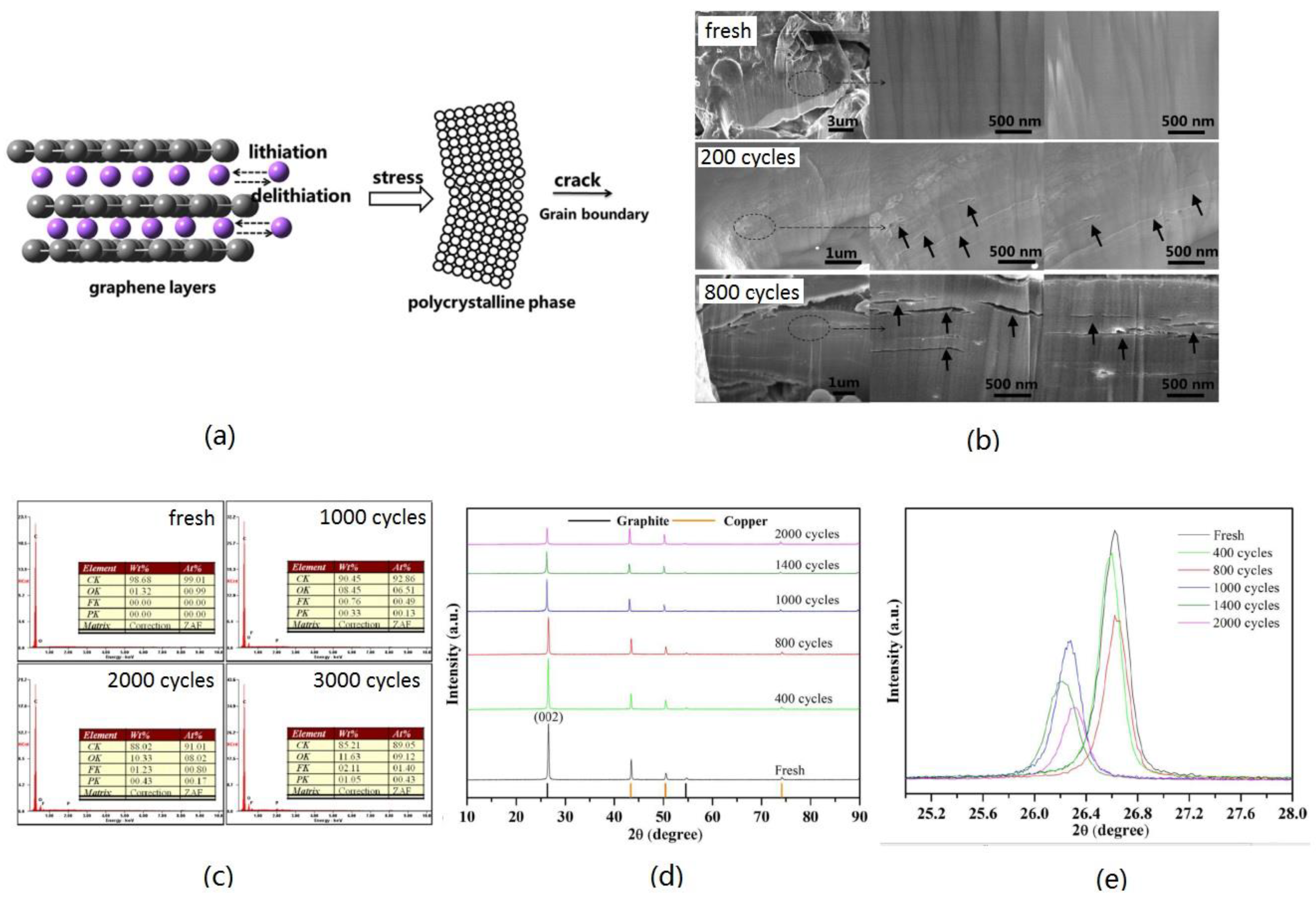
3.2.2. Structure Deterioration

The structure degradation of graphite anodes in commercial LIBs is related to cycling numbers and charge rates. Stress induced during the lithiation and delithiation initiates and propagates cracks. Figure 7a shows that these cracks occur along grain boundaries [58]. During the long-term cycling, the micro-cracks expand, causing volume expansion of the graphite particle and the overall cell volume [59]. Figure 7b illustrates the SEM images of fresh and cycled anodes, revealing cracks occurring on the graphite particles after cycling, indicating the physical damage caused by the inherent volume change [58]. Particularly, higher charge rates increase the likelihood of anode electrodes cracking, given graphite’s higher tensile strength [54]. In addition, the EDS spectra and related test results of the surface of the anode electrodes are shown in Figure 7c [54]. No signal for F and P was observed on the fresh electrode, signals indicative of F and P were present on all cycled electrodes, and O, F, and P elements are the major components of SEI films, as mentioned above. So, we can draw the conclusion that the uninterrupted volume change among graphite particles leads to the generation and agglomeration of composites [60]. These composites may be the result of the recombination/repair of the SEI layer and the reaction of electrolytes with the newly exposed anode surface [61]. Cycled graphite internal structural analyses of full XRD pattern spectra and the characteristic (002) peaks plot (Figure 7d,e) confirm graphite expansion and rupture during repeated lithiation/delithiation processes [62]. The volume changes introduce irreversible damage to the SEI layer, leading to carbon negative/electrolyte interface instability, suspected as the cause of lithium inventory loss. Since battery capacity hinges on active lithium quantity, the capacity loss directly correlates with the loss of active lithium [63]. In conclusion, the structural degradation of the graphite anode prompts active Li+ consumption for SEI film repair and side reactions and causes the loss of active material due to the material expanding and rupturing.

3.2.3. Growth of Lithium Dendrites

The lithium plating reaction of LFP batteries most likely first occurs at the anode–separator interface, which is greatly affected by the lower ambient temperature and higher current rate. These factors influence both the kinetics and the diffusion rate of Li+, leading to the deposition of lithium on the anode electrode’s surface (Figure 8a) instead of Li+ intercalating into the graphene interlayers. Lithium is easier to deposit owing to the decreased solid diffusion coefficient and lower anode potential at low temperatures. Furthermore, lithium deposition may break the SEI film at a high current density owing to stress, which will repair the SEI film and increase its thickness [64]. Consequently, the electrolyte reacts with lithium to produce a new SEI film on the deposited lithium surface, exacerbating the loss of cycled lithium and thickening the SEI film once more [65], and the increased thickness elevates resistance (Figure 8b) [66]. Non-uniform lithium deposition on the anode surface may cause protrusions on the SEI film [67]. Over time, some of these protrusions can develop into lithium dendrites, capable of piercing the separators and causing internal short circuits, which significantly risks battery safety. Moreover, as lithium plating progresses, portions of the deposited lithium may fracture and detach. When the deposited lithium is completely wrapped by the insulating SEI, it cannot be reversed to active lithium, which leads to a continuous decrease in the lithium source in the battery and a decrease in battery capacity [65,68]. A framework combining incremental capacity analysis (ICA) and model simulations quantified that the pace of loss of lithium inventory quadrupled with the emergence of lithium plating [69]. Additionally, the active material encapsulated by the deposited lithium experiences part volume expansion, resulting in an increase in mechanical stress [66,68]. This stress can induce the active material cracking during cycling, resulting in further reduction in anode capacity. In conclusion, lithium dendrite deposition can lead to the loss of cyclable lithium and cause an internal short circuit, resulting in severe capacity degradation and safety hazards for LFP batteries.

4. Enhancement Strategies

The capacity fade of LFP batteries primarily stems from several factors, including phase transition, CEI layer formation, Fe dissolution from cathode active materials, the decomposition of electrolytes, SEI film thickening, structure deterioration of anode materials, and lithium dendrite growth. Consequently, in order to improve the electrochemical performance of LFP batteries, three main aspects can be optimized: cathode, anode, and electrolyte (Figure 9).

4.1. Doping

Given that electrons preferentially transport along the ac plane while Li+ diffuses along the b-axis direction in LFP, it is reasonable to assume that the doping effect on electron and ion conduction may vary by site [70,71]. Both X-ray absorption experiments [72] and first-principles calculations [73] indicate that doping enhances electronic conductivity. Various doping types, such as lithium site substitution, iron site substitution, and polyanion doping, are helpful in improving the structural stability of LFP, which increases the Li+ diffusion coefficient and reduces the charge transfer resistance. The enhancements significantly impact electrochemical performance, even in extreme environments.

4.1.1. Lithium Site Substitution

Substituting Li+ with other metal ions significantly enhances the electrochemical performance of LFP. First-principle calculations reveal that substituting Li+ with Na+ not only enhances electronic conductivity but also improves ionic transport characteristics, making it more favorable for high-rate performance compared to pure LFP [74], so the sample substituting Li+ with an appropriate amount of Na+ showed superior cycle stability and improved rate capability, e.g., Li0.99Na 0.01FePO4 demonstrated remarkable capacity retention, maintaining 86.7% after 500 cycles at 10C. This performance can be attributed to its unique ac facet morphology and expanded lattice parameters in a and c. Meanwhile, introducing a suitable amount of Na significantly reduces the charge transfer resistance, as illustrated in Figure 10a [75,76]. Moreover, Nb doping was observed to widen the one-dimensional diffusion channels of Li+ along the [010] direction, thus enhancing Li+ diffusivity. With its various valences, Nb tends to induce n-type doping, thereby improving the electron conductivity of the materials. The improved electrochemical performance indicates that the Nb doping can enhance the electrochemical property of LFP/C [77]. Compared with pristine LFP, the Li1−x−vVxFePO4 shows higher capacity (Figure 10b) and conductivity, which are attributed to the substitution of V at the Li site and the consequent generation of Li vacancies. This was confirmed by ex-situ X-ray absorption near edge structure (XANES) results, as shown in Figure 10c [78]. It is also because of the increased concentration of lithium vacancies; the LFP cathode material, upon partial substitution of lithium by aluminum, improved the electrochemical performance [79]. In addition, defects were generated with two positive charges after Y3+ substituted Li+ and iron atomic holes were generated, leading to positive hole conduction, which reduced the material’s resistance and enhanced its conductivity. Meanwhile, the grain size of Y-doped LFP decreased, and its grain morphology became more uniform compared to undoped LFP, as illustrated in Figure 10d,e, which increased the Li+ diffusion and improved the conductivity, so the electrochemical performance improved [80]. Tian et al. [81] prepared a series of samples of lanthanum-doped Li1–xLaxFePO4 by the solid-state synthesis method. The optimum sample, Li0.99La0.01FePO4 showed higher capacities and better long-term stability than other cells. The roles of La include reducing particle size to the nanoscale, enhancing electrical conductivity, and affecting charge transfer resistances in cells based on the doping amount. In comparison to pure LFP, the unit-cell parameter and volume of Li0.98Cu0.01FePO4 are both reduced. This is due to the smaller ion radius of Cu 2+ compared to Li+, resulting in a decrease in the length of the c-axis. Additionally, the stronger binding force between Cu 2+ and O2− compared to Li+ and O2− leads to the shrinkage of the unit-cell volume of Li0.98Cu0.01FePO4. These reasons cause the electrochemical performance of Li0.98Cu0.01FePO4 to be better than LFP [82]. Similar to the influence mechanism of Cu doping, doping with 1% Ti4+ (molar fraction) improves electrochemical performance, delivering an initial specific capacity of 146.7 mAh/g at a 0.3C rate. Electrochemical impedance results indicate that doping an appropriate amount of Ti4+ significantly reduces the charge transfer resistance of the sample (Figure 10f) [83].
All in all, the influence mechanisms of doping Na, Y, V, Cu, etc., at the Li site include widening the one-dimensional diffusion channels for Li+, inducing lithium vacancies in the crystal structure, reducing the grain size and making the grain morphology more regular, and shrinking the unit-cell volume, which enhances the electrochemical performance greatly. However, excessive guest ions doped on Li sites may block the diffusive path of Li+ since the diffusion coefficient of Li+ is primarily fast along the tunnel c-axis [84]. This is also the reason why different amounts of guest ion doping are studied.

4.1.2. Iron Site Substitution

Substituting cations at the Fe site (M2 site) in LFP typically leads to higher ionic mobility and Li+ diffusion coefficients. This is attributed to the cell volume expansion and weakened Li-O interactions, a phenomenon known as the pillar effect. It reinforces the layered crystalline structure, preventing collapse during the lithiation/delithiation. Weakened Li-O interactions reduce charge transfer resistance, enhancing cyclic reversibility. In addition, first-principle calculations indicate that metal ion doping at the Fe site facilitates Li+ diffusion along the 1D pathway, increasing electronic and ionic conductivity [85]. For example, Zn and Ru doping preserve LFP’s lattice structure, providing a more stable lattice structure, and the doped atoms protect the LFP crystal from shrinking during lithiation/delithiation. This kind of “pillar’’ effect expands space for Li+ movement, thus improving conductivity and Li+ diffusion coefficients. These enhancements ultimately boost the discharge capacity and rate capability of LFP [86,87,88]. The olivine-type LFP structure and the doping sites of V atoms on Fe atoms are depicted in Figure 11a [89]. Vanadium doping reduces the barrier of Li+ diffusion along the one-dimensional channel in both LiFePO4 and FePO4 phases (Figure 11b). Structural analysis reveals that the lower diffusion barrier is closely tied to the volumetric expansion of the diffusion channel. Proper V doping refines the LFP particle size, induces lattice distortion, and weakens the Li-O bonds, thereby enhancing Li+ diffusion and electronic conductivity, resulting in improved electrochemical performance of LFP/C composites (Figure 11c) [90]. Co-doping strengthens the PO4 structure and also weakens the Li-O band, thus leading to the superior electrochemical performance of the LiFe0.99Co0.01PO4/C composite [91]. Cupric substitution enlarges the interplanar distance of planes parallel to the [010] direction of the LFP crystal, widening the diffusion channels of Li+ along the same direction. Cupric ion-substituted LFP/C composites exhibit improved electrochemical activity for Li+ storage compared to LFP/C [92]. The LiTi0.08Fe0.92PO4 cathode demonstrates enhanced specific capacities, higher capacity retentions, and good rate capabilities (Figure 11d), likely owing to the improvement in ionic migration pathways formed by the strategically placed NASICON particles between the olivine particles [93]. An appropriate amount of Mo doping at the Fe site preserves the olivine structure of LFP while significantly enhancing Li+ diffusion compared to the undoped materials [94]. Similarly, appropriate Mn2+ doping increases electronic and ionic transportation, enhancing the performance of LFP/C under extreme conditions [95,96]. However, the large radius and poor intrinsic kinetic properties of Mn in LFP/C lead to a negative cooperative effect, where the large radius benefits charge transfer but the poor intrinsic kinetic properties hinder electrochemical reactions [97]. Doped Ni reduces electrode polarization and electrochemical impedance compared to pure LFP, achieving a specific capacity of 175.8 mAh·g−1 at 0.2C after sufficient activation, surpassing the theoretical value of 170 mAh·g−1 (Figure 11e) [98]. Rh substitution enhances the rate capability of LFP/C, with the LiFe0.975Rh0.025PO4/C sample demonstrating a high-rate performance and a longer cycling life than LFP/C at high temperatures [99]. Ce doping optimizes crystal microstructure and particle size, decreases charge transfer resistance, and improves electrical conductivity and Li+ diffusion rate in LFP/C. The LiFe0.9Ce0.1PO4/C has good cycle performance; that is, the capacity retention ratio is 99.6% after 100 cycles of 1 C [100]. Furthermore, proper Sm doping at the Fe site improves electronic conductivity and Li+ diffusion while reducing charge-transfer resistance [101].
In conclusion, substituting iron ions is a straightforward method for enhancing both the structural stability and electrochemical properties of LFP cathode materials, and it can enhance their performance even in extreme environments. Moreover, to further enhance the electrochemical performance through synergistic effects, co-doping at the Fe site has been adapted, such as co-doping Ni and Mn at the Fe site, co-doping Ti and V at the Fe site, etc. [102,103]. However, similar to the lithium site substitution, the amount of element doping is too much; it could hinder the Li+ diffusion during the cycle, which would have a negative impact on electrochemical performance. Therefore, it is very important to carefully adjust the amount of substitution in the synthesis process to optimize its properties.

4.1.3. Polyanion Doping

Polyanion doping has been used to improve the properties of LFP materials, significantly influencing the stability of LFP’s crystal structure, Li+ insertion/extraction rate and pathway, and electronic conductivity. Doping can occur at the P site and O site. Fluorine doping induces the closure of gaps in the electronic structure, thereby improving the conductivity properties of the doped compound. Rietveld refinement analyses indicate that fluorine ions preferably occupy specific oxygen sites [104]. Owing to the distinct ionic radius and electronic configurations of F and O2−, fluorine doping can modify lattice parameters, increase lattice volume, adjust interatomic distances, narrow the band gap, and reconfigure the electron cloud, resulting in enhanced high-rate performance and cycling stability, reduced polarization, decreased charge transfer resistance, and an improved diffusion coefficient of Li+. The fundamental rationale behind the enhanced electrochemical performances lies in F doping’s ability to boost electronic conductivity, accelerate the Li+ diffusion coefficient, and maintain structural stability [105,106]. In addition, the F-doped samples exhibit significantly improved cycling life at elevated temperatures compared to the undoped sample (Figure 12a) [107]. Cl doping enhances the electrochemical reaction during cycling, thereby improving high-rate performance primarily through enhanced Li+ diffusion, which is facilitated by Cl’s incorporation into the lattice of the olivine structure, weakening Li-O bonds [108,109]. Additionally, Cl doping effectively alters the microstructure, enhances structural stability, and boosts rate performance (Figure 12b) [110]. S doping in the LFP matrix expands the lattice due to the larger ionic radius of S2− compared to O2−, which also suppresses F e L i . antisite defects in Li+ diffusion channels. These defects promote the easy migration of Li+ without channel blockage, leading to enhanced electrochemical properties. As a result, S-doped LFP nanoparticles exhibit improved electrochemical properties, with a high discharge capacity of ~113 mAh g−1 even at a high rate of 10C [111]. Moreover, sulfur doping in LFP material can also improve its performance at high temperatures. The LiFePO3.98S0.03 cell demonstrates nearly identical discharge capacities (~155 mAh g−1) across all temperatures studied, exhibiting stable behavior [112]. With boron doping LFP at the P site, the proper amounts of B can decrease the particle size and agglomeration relatively, improve Li+ diffusion coefficients and electronic conductivity, and enhance discharge capacity, cycling stability, and rate performance. However, excessive B doping may induce oxygen defects in the material, leading to reduced active lithium content and unfavorable electrochemical performance [113,114]. Regarding N doping in LFP, first-principle investigations reveal that substituting nitrogen for oxygen on the (010) surface of LFP (Figure 12c) is energetically favorable, which can significantly reduce the band gap of LFP, indicating improved electronic conductivity. Research indicates that on pure LFP (010) surfaces, the substantial intrinsic activation energy of Li+ diffusion impedes rapid Li transport. Nevertheless, this barrier can be significantly diminished through nitrogen surface modification (Figure 12d). N doping on the LFP (010) surface holds the potential to enhance both its electron conductivity and ion diffusion characteristics [115,116].

4.2. Coating

Above all, the doping of lithium site substitution, iron site substitution, and polyanion doping on LFP are pivotal in improving electrochemical performance, including rate performance and cycle stability. In addition, they bolster structural stability and enhance performance even in extreme environments, etc. In order to further improve the electrochemical performance through synergistic effects, co-doping or co-substitution at the Fe site was adopted, as mentioned above. Similarly, co-doping at the Li site and Fe site, co-doping at the Fe site, polyanion doping, and various combinations of the three kinds of doping were adopted to improve the performance [85,117,118,119]. Of course, doping with other elements to improve the electrochemical performance of LFP is also worth studying.
As is well known, the low intrinsic electronic conductivity of LFP and the low diffusion coefficient of Li+ are primary limitations hindering its industrial application. Surface coating with electronically conductive layers has proven remarkably effective in boosting the electronic conductivity of this material. Various coating materials, such as carbon, metal, metal oxide, conducting polymers, etc., have been explored to enhance the performance.

4.2.1. Carbon Coating

Carbon coating stands out among various coating materials for its exceptional conductivity, electrochemical stability, affordability, and ease of application. This approach significantly enhances electronic conductivity and the kinetics of lithiation and delithiation, and avoids the aggregation of nanoparticles. The carbon-coating effectively prevents the agglomeration of the nano LFP, ensuring that embedded LFP primary nanocrystallites receive electrons and Li+ from all directions. The high-rate performance and cycle stability of the LFP@C composite are mainly attributed to its uniform coating morphology and low contact resistance between active material particles [120,121]. To further enhance the performance of carbon coating, some improved methods were adopted, e.g., coating Super P (SP) on LFP/C enhances the surface area and pore structure. The optimized LFP/C-SP5 cathode exhibits a capacity of 165.6 mAh/g at 0.1C and exceptional rate performance with a capacity of 59.8 mAh/g at 10C [122]. Additionally, using calcium lignosulfonate as one of the carbon sources results in the formation of a thin layer of calcium-doped carbon on the surface of LFP particles, which is expected to reduce side reactions between LFP and electrolytes and improve electrode stability. Compared to the LFP/C samples prepared by the solid-state method, derived LFP/C composites demonstrate excellent rate performance, cycle life, and low-temperature capability (Figure 13a) [123]. The attachment of fluorine-doped carbon (FC) onto the surface of LFP particles creates a three-dimensional (3D) conductive network structure, fostering excellent grain-to-grain electrical contact, minimizing Li+ diffusion distance between grain interfaces, and facilitating rapid electron transfer during charge/discharge. This configuration results in exceptional electrochemical performance in LIBs, with superior rate performance and cycling stability (Figure 13b) [124]. Additionally, nitrogen-doped carbon networks surrounding lithium iron phosphate nanoparticles promote the transfer of Li+ and electrons throughout the electrodes, reducing internal resistance and enhancing LFP’s efficient utilization (Figure 13c) [125]. Moreover, boron-doped carbon coating introduces significant defects, enhancing the electronic conductivity of LFP. Consequently, the boron-doped composite exhibits superior rate capability and cycle stability compared to the undoped sample, maintaining a high capacity of 126.8 mAh g−1 even at a high rate of 10C, with a capacity retention ratio of about 98.2% after 100 cycles [126]. Last but not least, highly graphitized advanced carbon materials (carbon nanotubes, graphene, etc.) possess exceptional electronic conductivity, high specific surface area, and excellent structural stability, making them superior to traditional carbon materials for coating LFP and addressing rate performance limitations [11], e.g., multilayer graphene films decorating carbon-coated LFP nanospheres create a unique 3D “sheets-in-pellets” and “pellets-on-sheets” conducting network structure, rich in mesopores, enhancing rate and cyclic performance by promoting electronic and ionic transport (Figure 13d) [127]. Carbon nanotubes embedded within LFP nanoplates, with graphene nanosheets coating the surface, form a crosslinked three-dimensional mixed conducting network, accelerating both electron conduction and ion diffusion, resulting in significant improvements in specific capacity and cycling performance (Figure 13e) [128]. Furthermore, a biomimetic composite comprising litchi-like LFP spheres assembled with 20 nm nanoparticles and reduced graphene oxides (rGO) facilitates short electron transfer pathways within and on the surface of LFP spheres, exhibiting high capacity, good coulombic efficiency, and high capacity retention even at −5 °C (Figure 13f) [129]. However, excessive carbon negatively affects tap density and energy density, underscoring the need to optimize carbon content during the coating process. Among the carbon-coated samples, LFP/C composites with 1.65 wt% carbon display the best initial discharge capacity and coulombic efficiency, attributed to the low Rsf value and preferential orientation of the (010) plane [130].

4.2.2. Other Layers

Besides carbon coating, metal, nonmetal, metal oxide, nonmetal oxide, phosphide, etc., can also be used as modification materials on the surface of LFP materials, which have a great effect on the electrochemical performance. Compared to pristine LFP/C, the Sn-coated LFP/C exhibits improved electric contact among particles, significantly reduced charge-transfer resistances, and enhanced Li+ diffusion rates, particularly at low temperatures. Furthermore, the Sn-coating layer shields the active materials from chemical attack by HF, thereby mitigating the dissolution of Fe from LFP in LiPF6-based electrolytes [131]. Moreover, uniformly dispersing small fractions of silver (approximately 1.37 wt%) throughout the LFP film enhances electrical conductivity, resulting in a favorable combination of moderate specific capacity, stable cycling, and notably, exceptional tolerance against high rates and over-charging and -discharging [132]. The surface modification of the nano-sized Si with a crystalline Si core and amorphous Si shell yields reduced coarsening, improved rate performance, and enhanced cyclic performance at high current densities, particularly at elevated temperatures (Figure 14a). Moreover, the surface modification of nano Si protects the active material from undesirable side reactions between the electrolyte and electrode, consequently suppressing the degradation of LIBs [133].
The typical oxide coatings enhance the cycle stability, rate performance, and low-temperature capabilities, decreasing the capacity fading. SiO2 on the LFP particle surface effectively prevents direct contact with the electrolyte solution, improving structural stability, reducing interfacial resistance, and enhancing Li+ conductivity. It also regulates Li+ insertion into the lattice, enhancing the order of Li+ occupation in the outer lattice of the particle [134]. CeO2-coated and V2O3-modified LFP/C cathode significantly improved electrochemical performance at low temperatures and rates. This improvement is attributed to reduced electrode polarization, enhanced electrical contact between cathode grains and the current collector-to-particles, and increased charge-transfer reaction activity at the LFP/C-electrolyte interface [135,136]. The positive surface modification effect of the SnO2 layer reduces material degradation during charging/discharging cycling, exhibiting excellent lithium intercalation reversibility in modified LFP, demonstrating outstanding coulombic efficiency, almost reaching 100% (Qdc/Qc), compared to the 97% efficiency of pure LFP [137]. Significant improvements in capacity and cycling stability at high charge/discharge rates can be achieved by nano-sized CuO and carbon co-coatings. The capacity fading of the CuO/C-LFP electrode is reduced to 1.6% after 20 cycles at a 1C rate [138]. Furthermore, metal composite oxide and ion-doped metal oxide coatings provide a new idea. ZnAl2O4 coating has many advantages, as follows: it enables the rapid and enhanced diffusivity of Li+ into the LFP surface, enhances resistance to HF acid attack, improves chemical and thermal stability, reduces ohmic (Rs) and interfacial resistance (Rct), and decreases chemical diffusion resistance at the solid–electrolyte interface region. Essentially, ZnAl2O4 coating significantly enhances the stability of the crystal structure and provides additional conduction pathways for lithiation/delithiation [139]. Surface treatment with aluminum-doped zinc oxide (AZO) coating greatly enhances the rate capability and low-temperature capabilities of LFP (Figure 14b), which can be assigned to the electrically conductive coating, increasing the electronic conductivity of LFP and the tap-density of LFP [140].
Nitrides, carbides, fluoride, phosphide, and phosphate were also utilized as surface modification materials for LFP. Nano-sized TiN particles, along with an amorphous carbon layer, formed an integrated network on the LFP surface, improving electrode activity and kinetics, resulting in reduced charge transfer resistance and an improved Li+ diffusion coefficient, which effectively enhances the discharge capacity and cycle stability, particularly at high rates (Figure 14c) [141]. Compared with the pristine LFP/C, Ti3SiC2-modified LFP/C samples exhibited lower charge-transfer resistance and higher Li+ diffusion coefficients, especially for the 4 wt% Ti3SiC2-modified samples at low temperatures, attributed to the conductive “bridge” effect facilitated by well-dispersed Ti3SiC2 [142]. LiF modification enhanced Li+ diffusion into the lattice due to better crystallinity and smaller particle size, achieving a high-rate capacity of 112.2 mAh g−1 at 10C, with stable cycling performance for LFP [143]. The electronic conductivity of the LFP/Fe2P composite increased with the Fe2P phase amount, particularly evident in the sample containing 8% Fe2P, showing high discharge capacity and rate capability at high current densities (Figure 14d) [144]. In addition, the co-coating effect of phosphate and carbon on the LFP cathode surface also has been studied and was shown to protect LFP from electrolyte corrosion and enhance its ion and electron transport ability, thereby ensuring its stability and increasing its capacity retention and rate performance [145,146,147].
Conductive polymers have garnered significant attention in recent decades for their unique semi-conducting and optoelectronic properties. The combination of LFP with conductive polymers has emerged as a promising avenue, enhancing electronic conductivity and Li+ surface exchange, especially showing good electrochemical performances in a wide temperature range. Composites such as Polypyrrole (PPy)/Polyethylene glycol (PEG) coatings on LFP particles improve electron transport via the resulting polymer network and Li+ exchange, leveraging PEG’s excellent salt dissolving property. This configuration ensures stable and reversible capacity, achieving a high capacity of ca. 100 mAh g−1 even under high-rate cycles of 5C [148]. Similarly, the coating of polythiophene (PTH) significantly improves LFP’s electronic conductivity, facilitating charge transfer reactions. The 10.56 wt.% LFP/PTh composite exhibits superior cycle ability and excellent rate capability (Figure 14e) [149]. Nanosized LFP particles coated with a uniformly thin polyacene (PAS) layer exhibit low polarization and excellent electrochemical performance across a wide temperature range of −20 °C to 60 °C [150]. In addition, conductive polymers and carbon co-coated LFP composites were also studied, as shown in Figure 14f. Compared with the PAS-coated LFP, the PAS/carbon-coated LFP showed lower charge transfer resistance (Rct) and a higher Li+ diffusion coefficient due to the double coating layer (PAS and carbon) and the small grain size. The dual PAS/carbon coating layer enhanced both initial discharge capacity (161.7 mAh g−1 at 0.2C) and capacity retention (99.7% after 50 cycles), ensuring ideal conductivity, electrolyte wetness, and the hindrance of direct contact between electrolyte and active particles [151]. Meanwhile, a novel electrode of free-standing poly (3,4-ethylenedioxythiophene) (PEDOT)-LFP composite films was successfully developed, eliminating electrochemically inactive materials (carbon, polymer binder, and current collector) commonly adopted in conventional cathodes. Despite this, the high discharge capacity of ~160 mAh g −1 is preserved, considering the relative amount of LFP in PEDOT-LFP film, offering a promising avenue for the exploration of ionic/electronic conducting support structures for LFP particles [152].
Figure 14. (a) Cycling performance of LiFePO4@C and LiFePO4@C/Si at 1 C under 60 °C between 2.5 and 4.3 V [133]; (b) initial discharge curves of undoped-LiFePO4 and AZO-LiFePO4 powders tested at −20 °C [140]; (c) cycling stability of 5 wt% TiN-LiFePO4/C and LiFePO4/C at the current rate of 1C [141]; (d) electronic conductivity of LiFePO4/Fe2P composite as function of Fe2P concentration and an initial discharge capacity at C/20 and C/1 current rate (between 2.5 and 4.3 V) [144]; (e) the rate and cycling capability of bare LiFePO4 and LiFePO4/PTh composite at various C rates [149]; (f) schematic diagrams of the double coating process of PAS/carbon-coated LiFePO4 [151].
Coatings 14 00832 g014
As mentioned above, the carbon material is the main coating method, which leads to a great improvement in electronic conductivity directly, delivering better rate capability and cycle stability. However, carbon coating cannot improve the electrochemical performance at low or elevated temperatures and other conditions. Therefore, metal, nonmetal, metal oxide, nonmetal oxide, phosphide, etc., can also be used as modification materials on the surface of LFP, which protects the active material from undesirable side reactions between the electrolyte and electrode, shows higher rate performance and better cycle stability, particularly at low or elevated temperatures, and decreases capacity fading. So, we can conclude that the coating is an effective way to enhance the electrochemical performance of LFP.

4.3. Microstructure Control

The reduction in particle size of olivine LFP is widely acknowledged as an effective approach to enhance electrochemical performance, which shortens the Li+ and electron transportation path, alleviating strain during the phase transition of LiFePO4 and FePO4. Additionally, it has been noted that the rate capability of LFP is predominantly influenced by its specific surface area, further emphasizing the effectiveness of minimizing particle size. Delacourt et al. [153] synthesized carbon-free LFP powders with a narrow particle size distribution of around 140 nm, resulting in exceptional electrochemical performance, showing a discharge of 147 mAh g−1 at a 5C rate with negligible capacity fade over 400 cycles. In addition, LFP nanoparticles, synthesized via a polyol process, exhibited various shapes such as nanorods and nanoplates, with an average size of 300 and 100 nm, respectively. The decrease in particle size was evident in the initial discharge curve, with a capacity of 168 mAh g−1 at the 0.1C rate, reaching 98% of the theoretical specific capacity [154]. Moreover, carbon-coated LFP particles with reduced size, a geometric mean diameter of 146 nm, and a geometric standard deviation of 1.4, demonstrated first discharge capacities of 165 mAh g−1 at 0.1C and 105 mAh g−1 at 20C while maintaining excellent rate performance with no capacity fading after 100 cycles across various rates from 1 to 60C owing to the decreased particle size [155].
Controlling morphology is another effective method for enhancing the electrochemical performance of LFP. A hollow structure (Figure 15a) provides a shorter pathway for Li+ diffusion and void space to accommodate stress induced by volume changes during cycling, improving electrode stability and Li+ diffusivity, leading to the enhanced rate capability and cycle performance (Figure 15b) [156,157]. In addition, porous electrode materials (Figure 15c) offer a large specific surface area and porous structure, enhancing the contact between electrolyte and active material and the structural stability during the cycling processes and reducing Li+ diffusion length for lithiation/delithiation. Therefore, the porous electrode shows good cycle stability and exceptional rate performance (Figure 15d). They are regarded as promising methods for enhancing LFP electrode performance [158,159].
All in all, the enhanced strategies of doping, coating, and microstructure control all have great effects on the electrochemical performance of LFP cathodes. Among them, the methods of reducing the size and carbon coating are the most economical and direct and also the simplest, which greatly affects the conductivity and the Li+ diffusion coefficient, showing better cycle stability and rate performance. The properties of LFP cathode materials are affected not only by their own structures but also by the side reactions between the material particles and the electrolyte interface. However, suitable doping and coating can significantly improve the electrochemical properties and temperature adaptability of LFP.

4.4. Electrolyte

We described the methods of cathode modification as mentioned above. Meanwhile, the modifications of electrolytes are also crucial for enhancing the electrochemical performance of LFP cathode materials or achieving certain functions of batteries. While the precise composition of mixed solvent may vary, a fundamental mixture typically includes ethylene carbonate (EC) with a cyclic structure, alongside one or more dialkyl carbonates with a linear structure: dimethyl carbonate (DMC), diethyl carbonate (DEC), and ethylmethyl carbonate (EMC) [160]. However, the abundance of flammable organic solvents poses a safety problem for batteries [161]. Meanwhile, LiPF6 is the predominant lithium salt utilized in commercialized LFP batteries due to its superior ionic conductivity, favorable electrochemical window, and beneficial interface formation properties on graphite anodes and Al current collectors compared to other lithium salts. Nevertheless, LiPF6 is susceptible to degradation in organic carbonate solvents, especially under elevated temperatures or catalyzed by traces of water in the electrolyte. The resulting decomposition products, HF and PF5, can dissolve metal moieties in cathode materials and react with carbonate solvents, thus diminishing battery capacity and increasing impedance [162]. Consequently, there is an urgent need to develop a new electrolyte system with enhanced thermal and electrochemical stabilities for LFP batteries.
Firstly, significant efforts have been devoted to advancing the core technology of novel lithium salts for LFP batteries. Lithium bis (trifluoromethanesulfonylimide) (LiTFSI) emerges as a promising alternative to Li salt due to its high stability against water and heat. However, its strong corrosion tendency on the Al current collector (around 3.7 V vs. Li+/Li) is fatal [163]. Li et al. [164] discovered that incorporating an appropriate amount of lithium difluoro (oxalate) borate (LiODFB) into the LiTFSI electrolyte effectively mitigates aluminum corrosion. Furthermore, LFP-based batteries utilizing LiTFSI0.6-LiODFB0.4-based electrolytes exhibit superior cycling stability and rate capability compared to those using LiPF6-based electrolytes (Figure 16a). In addition, synergistic effects between lithium bis(fluorosulfonyl)imide (LiFSI) and lithium bis-oxalato borate (LiBOB) salt in LiPF6/EC/EMC electrolyte were investigated by Zhang et al. [165]. Incorporating 0.2 mol L−1 of LiFSI into 1.0 mol L−1 LiPF6-based electrolytes effectively enhances the cycling stability and rate performance of the graphite anode. However, the LFP cathode faces challenges in cycling due to severe corrosion of the aluminum current collector by LiFSI. To address this issue, 0.2 mol L−1 LiBOB was introduced, effectively passivating the aluminum current collector and suppressing the corrosion caused by FSI anions. Additionally, LiFSI aids in reducing high impedance at the electrode/electrolyte interface arising from LiBOB salt. Consequently, full cell tests of LFP cathodes and the graphite anodes based on the LiPF6/LiFSI/LiBOB ternary-salt system demonstrated a commendable capacity retention ratio of approximately 84.3% after 200 cycles at 1 C rates, with a high average coulombic efficiency exceeding 99.8%. Furthermore, a novel single-ion gel polymer electrolyte emerges as a promising candidate for next-generation LIBs. The single-ion gel polymer electrolytes, including EC/DMC swollen polymeric lithium pentaerythrite borate (PLPB)@poly(vinylidenefluoride-co-hexafluoropropene)(PVDF-HFP) and polymeric lithium di(trimethylolpropane) borate(PLDB)@PVDF-HFP, exhibit favorable ionic conductivity across a wide temperature range, superior electrochemical stability, significantly high amounts of lithium ions, and effective Al passivation. LFP batteries utilizing these single-ion conducting electrolytes demonstrate stable charge/discharge behavior and outstanding cycle performance, both at room temperature and elevated temperatures [166].
Secondly, incorporating functional additives stands out as a highly effective and economical means to optimize electrolyte composition and improve the performance of LFP batteries. The SEI protecting layer emerges as a crucial factor for facilitating rapid kinetics and broad temperature suitability, particularly for enabling the fast charging of cells with graphite as anodes. Novel electrolyte additives such as fluorosulfonyl isocyanate (FI) [167] and tetraethylammonium tetrafluoroborate (TEABF4) [168] have been introduced to promote the formation of a conductive SEI film on the graphite surface, leading to a significant reduction in resistance at the graphite/electrolyte interface. Consequently, Li/graphite cells with the two additives both exhibited better rate performance, and LFP/graphite cells displayed better electrochemical performance, which was caused by an effective and stable SEI film at the electrolyte/electrode interface. Trimethyl borate (TMB) [169] and Tris(trimethylsilyl) borate (TMSB) [170] are effective electrolyte additives for enhancing the high-temperature performance of LFP cells due to the enhanced thermal stability of the electrolyte. Notably, among the tested TMB concentrations, the highest (0.1 M) concentration yields optimal performance, showcasing significantly higher capacity retention and mitigated thermal decomposition of the LiPF6-based electrolyte after 100 cycles at 60 °C in tested cells, resulting in a reduced capacity fade of only 47%. Additionally, LFP batteries employing a composite LiPF6-based electrolyte containing 1 wt% TMSB additive demonstrate superior discharge retention and enhanced cycling performance compared to those without TMSB additive at both 30 °C and 55 °C. Low temperature has great negative impacts on LFP batteries. Consequently, various electrolyte additives, including organic (fluoroethylene carbonate (FEC)) [171] and inorganic (sodium chloride (NaCl)) additives, have been proposed to ameliorate the low-temperature performance [172]. EIS results (Figure 16b) indicate that the low-temperature performance of the LFP electrode was enhanced through the formation of an SEI film with higher ion conductivity and reduced electrochemical reaction polarization facilitated by FEC. This accelerates the migration of Li+ through the SEI layer and boosts the electrochemical reaction rate. Additionally, the inclusion of NaCl as an electrolyte additive added to low-temperature electrolytes led to a notable improvement, delivering a high capacity of 115 mAh g−1 at 2 C, 20 mAh g−1 more than its NaCl-free counterpart. To solve the flammability problem of carbonate-based organic electrolytes, the flame-retardant electrolyte additive is the simplest and most effective method to avoid safety hazards. The combustion rate of carbonate solvents containing three kinds of flame retardants (phenoxycyclophosphazene, phosphate, Tris (2-chloropropyl) phosphate) decreased to varying degrees, significantly altering the flame characteristics of the solvent samples. Notably, tris (2-chloropropyl) phosphate exhibited the most effective flame-retardant properties by significantly reducing the combustion rate of carbonate solvent and lowering the peak flame and fuel temperatures, thereby significantly enhancing solvent safety [173]. It was also found that the electrolyte containing 10% phosphazenic compound triethoxyphosphazen-N- phosphoryldiethylester (PNP) effectively mitigated the flammability concerns without seriously compromising cell performance. The capacity and cycling performance of an LFP cathode in 10% PNP electrolyte showed no significant change compared to the baseline electrolyte [174]. In addition, other functional additives are also studied, such as overcharge protection additives for LFP battery electrolytes. Cyclic voltammetry (CV) curves revealed that the monomer 9-Phenyl-9H-carbazole (9P9HC) could be electro-polymerized to form a conductive polymer on the cathode surface, preventing voltage runaway during overcharging. Charge/discharge tests of the LFP/C batteries demonstrated their ability to control voltage within a safe range below 4.2 V, with no significant impact on electrochemical performance over 50 cycles [175].
Thirdly, alongside the modification of lithium salts and additives, altering the entire electrolyte system represents another approach to enhancing LFP battery performance. For instance, the lithium sulfonylbis(fluorosulfonyl)imide (LiSFSI) electrolyte, supplemented with lithium bis(fluorosulfonyl)imide (LiFSI) additive, demonstrates excellent ionic conductivity σ (8.9 mS/cm at 30 °C), a transference number (tLi+) of 0.64, and anodic stability of 5.47 V. This combination results in high efficiency and improved specific capacity, reaching to 156 mAh g−1, with outstanding capacity retention (99.93%) even after 500 cycles in the full cell LFP/electrolytes/graphite battery system [176]. Another example involves the utilization of a binary eutectic mixture of lithium LiFSI and potassium bis (fluorosulfonyl)imide (KFSI) molten salt electrolyte in natural graphite/LFP cells, despite exhibiting a low capacity ranging from 71 to 86 mAh g−1 due to a substantial irreversible capacity (71 mAh g−1) during the first cycle, maintaining a specific capacity of 71 mAh g−1 after 100 cycles at 80 °C [177]. Furthermore, the introduction of 3-((Trimethylsilyl)oxy) propionitrile as a non-volatile solvent for LIBs electrolytes, alongside bis(trifluoromethanesulfonyl)imide (LiTFSI) as a lithium salt, enhances both thermal and chemical stability, thereby improving safety compared to conventional volatile carbonate electrolytes. In cell tests, the investigated LiTFSI nitrile silyl ether electrolyte proves to be compatible with both LFP and graphite active materials (Figure 16c) [178]. The triglyme (TG)/lithium bis(fluorosulfonyl)amide (LiN(SO2F)2 (LiFSI)) 1:1 molar mixture electrolyte for high-safety lithium-ion secondary batteries showed relatively high thermal stability. Remarkably, extended charge/discharge cycles of the [LFP positive electrode|TG-LiFSI electrolyte|graphite negative electrode] cell result in 82% capacity retention after 100 cycles [179]. Additionally, an intelligent self-adaptable gel polymer electrolyte (GPE) built upon a novel copolymer with functional pendent groups facilitates lithium ion migration, enhances redox stability, catalyzes cyclization reactions, and mitigates combustion through a synergistic effect of these groups (Figure 16d). This innovation not only endows various batteries with superior long-term cycling performance at room temperature but also ensures thermal shutdown function at high temperatures and flame retardancy in fire exposure scenarios. Notably, an LFP/GPE/graphite pouch battery, initiating with a capacity of 24.06 mAh, retains 75.9% of its capacity and exhibits a coulombic efficiency of 99.6% after 200 cycles at 0.5 C and demonstrates outstanding resistance to mechanical damage, high temperatures, and flames, presenting a compelling proof of concept for extensively enhancing the safety of practical LIBs [180].
Figure 16. (a) Cycling performance of Li|LiFePO4 cells using 1 M LiTFSI0.6-LiODFB0.4 and 1 M LiPF6 [164]; (b) electrochemical impedance spectra of fully discharged LiFePO4 electrodes without FEC and with FEC at −20 °C [171]; (c) average values of the charge–discharge performance in LiFePO4 half cells at a 1C rate of the TMS-OPN-LiTFSI electrolyte in comparison to the EC/DEC (3:7)-LiPF6 electrolyte [178]; (d) the effects of DEVP segments in P(AN-DEVP)-based GPEs under different circumstances [180].
Coatings 14 00832 g016
In short, electrolyte modification can be studied from three aspects: novel lithium salts, functional additives, and new electrolyte systems, which can restrain side reactions and improve the performance of LFP batteries. The development of new lithium salts and the combination of multi-functional additives should attract more attention in future research, resulting in the development of more valuable new electrolyte systems. In addition, although the safety performance of LFP batteries is higher than ternary lithium-ion batteries, etc., it is still a great challenge. Therefore, in addition to addressing the electrochemical performance, the focus should also be on battery safety hazards, such as lithium dendrite growth at low temperatures and combustion at high temperatures.

4.5. Anode

As analyzed above, the degradations at the graphite anode involve the formation of an irreversible SEI layer, structural deterioration, and the growth of lithium dendrites. The modification of electrolytes (such as novel lithium salts and additives) proposed above can alleviate the problems of the unstable SEI film and the growth of lithium dendrites during the cycle, which affect the performance of the LFP batteries. In addition, coating, doping, and other methods to modify graphite anode materials can also solve the above problems to some extent. For example, Kim et al. [181] employed a straightforward sol–gel method to modified graphite with an amorphous Al2O3 coating. This layer enhances electrode material wettability, facilitating electrolyte infiltration into the graphite anode, thereby improving Li+ insertion kinetics and cycle stability. Surface-engineered graphite with 1 wt% Al2O3 demonstrates a reversible capacity of approximately 337.1 mAh g−1, even at a high rate of 4000 mA g−1, corresponding to 97.2% of the capacity obtained at a current density of 100 mA g−1. Additionally, a microwave-assisted coating method synthesizes a high-performance Si oxide-coated graphite flake (SGF) composite anode for LIBs. This SGF composite exhibits a reversible specific capacity of nearly 480 mAh g−1, retains 97% of its capacity at a current density of 2.5 A g−1 (approximately 5 C-rate), and maintains 94% capacity retention after 500 cycles, with an average coulombic efficiency exceeding 99.9%, thus it can be employed as a fast-charging LIB anode [182]. Furthermore, a Nitrogen-doped carbon-coating graphite (NHG@C) anode material with a hollow structure is developed through a facile and scalable process. This hollow structure, composed of graphite flakes with disordered orientation, facilitates electrolyte penetration and shortens Li+ diffusion pathways. The NHG@C anode material effectively limits side reactions between the organic electrolyte and superfine graphite, maintaining electrode structure stability during cycling, which exhibits excellent rate capability and achieves a high reversible capacity of 304 mAh g−1 at 1 A g−1 after 500 cycles [183].
Besides the advancements in graphite anode modification techniques, extensive research is being conducted on novel anode materials. Among these, spinel Li4Ti5O12 has great prospects owing to its high safety, relatively low manufacturing cost, and excellent cycle stability. Furthermore, Li4Ti5O12 exhibits a notably flat and high charge–discharge voltage plateau of approximately 1.55 V vs. Li+/Li, effectively preventing the formation of SEI films and lithium dendrites caused by electrolyte reduction decomposition below 0.8 V vs. Li+/Li [184]. Consequently, it greatly reduces active Li+ consumption in the first cycle, increases coulombic efficiency during cycling, improves compatibility with various electrolyte systems, facilitates Li+ diffusion across interfaces, and improves LIBs safety. However, its poor electrical conductivity and low lithium diffusion coefficient severely limit its rate capability, hindering practical applications for high-rate charging/discharging [185]. Moreover, silicon is also being employed as a promising LIB anode material. Compared with Li4Ti5O12 and graphite electrodes, it has the advantages of low cost, high theoretical capacity, and high safety [186,187]. Nevertheless, challenges such as low electronic conductivity, Li+ diffusion coefficient, huge volume expansion/shrinkage, and low initial coulombic efficiency during cycling impede the commercialization of Si-based anodes, indicating the need for further development [188]. The formation of SEI films poses a significant challenge for silicon-based anodes. Therefore, silicon-based materials still need great efforts to be studied. The primary hurdles to overcome remain the substantial volume effects and extremely low conductivity. As another one of the anode candidates, transition metal sulfides (TMSs) emerge as promising candidates for anodes, garnering increased attention due to their high theoretical capacity, cost-effectiveness, and eco-friendliness, which are based on the conversion reaction of lithiation/delithiation [189]. In contrast to graphite anodes, TMSs typically exhibit voltage platforms above 1.0 V, mitigating lithium dendrite formation and ensuring high safety. Furthermore, TMSs boast significantly higher theoretical specific capacity and electrical conductivity compared to Li4Ti5O12 [190]. However, the volumetric changes during cycling and side reactions with electrolytes of TMS materials also require numerous efforts to solve.

5. Conclusion and Outlook

Owing to the stable three-dimensional structure and the strong covalent bonding between the oxygen and phosphorus ions forming (PO4)3− polyanionic clusters of the LFP cathode, the batteries exhibited good cycle stability and thermal stability. LFP batteries are currently extensively used for power grids, new energy buses, and electric ships. However, irreversible phase transition, iron dissolution, and other factors will lead to capacity decline for LFP batteries. In addition, the low electronic conductivity and Li+ diffusion coefficient of the LFP cathode limit its further application. Therefore, analyzing the capacity fade mechanism of LFP batteries and putting forward promotion strategies is of significance.
This paper mainly analyzes the capacity fading mechanism of LFP batteries. We divide those physical and chemical reactions into two main aging modes, the loss of lithium inventory (LLI) and the loss of active material (LAM). The main reasons mainly involve three parts: cathode, anode, and electrolyte, which can be divided into seven parts: (1) irreversible phase transition; (2) the formation of the cathode–electrolyte interface (CEI) layer; (3) the dissolution of iron elements; (4) the oxidative decomposition of the electrolyte; (5) the repeated growth and thickening of a solid–electrolyte interface (SEI) film on the anode electrode; (6) the structural deterioration of graphite anodes; and (7) the growth of lithium dendrites. Among them, we concluded the influence of two different phase-change mechanisms (two-phase mechanism and solid–solution mechanism) on battery capacity fade for the first time, related to particle size and the rate of lithiation/delithiation, etc. The rarely mentioned formation of CEI deepens the cathode polarization and could thus, in part, explain the loss of lithium inventory, especially in an overcharged and high-temperature state. High temperatures are the main reason for iron dissolution, which leads to the loss of lithium inventory at the anode and the increasing polarization of the electrode. The formation of the SEI layer is the predominant source of Li+ loss and limits the accessibility of Li+ to the anode surface, leading to an increase in irreversible capacity. The structural deterioration of the graphite anode will cause the consumption of active Li+ to repair SEI film and cope with side reactions. Lithium plating increased the resistance and the internal short circuit, which induced severe capacity degradation and safety hazards for LFP batteries.
In order to solve these problems, various strategies based on doping, coating, and microstructure control of the cathode material, the design of the electrolyte, and the modification of the anode have been studied to effectively stabilize the LFP cathode and improve the electrochemical performance. Among them, the modification of cathode materials and electrolyte design are emphatically discussed, and the modification of anode materials is also briefly introduced. The doping of lithium site substitution, iron site substitution, and polyanion doping on LFP play an important role in improving structural stability, electronic conductivity, and performance under extreme conditions, etc. In order to further improve the electrochemical performance through synergistic effects, co-doping or co-substitution at the Li site and Fe site or polyanion and various combinations of the three kinds of doping were adopted to improve the performance. Carbon-coated LFP cathodes deliver better rate capability and cycle stability. Moreover, metal, nonmetal, metal oxide, nonmetal oxide, phosphide, etc., can also be used as modification materials on the surface of LFP, protecting the active material from undesirable side reactions between the electrolyte and electrode, showing higher rate capability and better cycling stability, especially at low or elevated temperatures, and decreasing the capacity fading. Microstructure control, reducing the particle size, and designing the morphology (hollow and porous structure) are effective methods to improve the rate and cycling performance. Electrolyte modification can be studied from three aspects: novel lithium salts, functional additives, and new electrolyte systems, which can restrain side reactions and improve the electrochemical performance of LFP batteries. Coating, doping, and other methods to modify graphite anode materials can also be used to improve the electrochemical performance. In addition, some new anode materials are also being widely studied.
In this paper, the effects of two different phase-change mechanisms of LFP cathodes on the battery capacity fade are put forward and have been confirmed in many papers, respectively, but there is no systematic comparative analysis of the effects of these two different phase-change mechanisms on the battery capacity in any paper. This is a point worthy of attention in future research. Due to the relatively low theoretical specific capacity of the LFP cathode, increasing the energy density of battery cells through modeling and experimental work on the electrode structure design is necessary. In addition, the fast-charging technology must make a major breakthrough in future research, which plays a vital role in the further development of electric vehicles. The poor electrochemical performance at low temperatures is another factor that limits the application of LFP batteries. It could be improved by choosing an appropriate new anode material, designing a novel electrolyte, optimizing the thermal management scheme, and charge/discharge methods. Last but not least, the hazards caused by safety problems cannot be ignored. Developing and utilizing higher thermal stability separators and solid-state electrolytes and also optimizing the thermal management scheme can greatly improve safety.

Funding

This work was supported by the Science and Technology Foundation of State Grid Corporation of China (5100-202155307A-0-0-00).

Institutional Review Board Statement

Not applicable.

Informed Consent Statement

Not applicable.

Data Availability Statement

The original contributions presented in the study are included in the article, further inquiries can be directed to the corresponding author.

Conflicts of Interest

The authors declare no conflict of interest.

References

  1. Armand, M.; Tarascon, J.M. Building better batteries. Nature 2008, 451, 652–657. [Google Scholar] [CrossRef] [PubMed]
  2. Goodenough, J.B. Energy storage materials: A perspective. Energy Storage Mater. 2015, 1, 158–161. [Google Scholar] [CrossRef]
  3. Dunn, B.; Kamath, H.; Tarascon, J.M. Electrical Energy Storage for the Grid: A Battery of Choices. Science 2011, 334, 928–935. [Google Scholar] [CrossRef] [PubMed]
  4. Zhang, L.-Q.; Zhu, C.-X.; Yu, S.-C. Status and challenges facing representative anode materials for rechargeable lithium batteries. J. Energy Chem. 2022, 66, 260–294. [Google Scholar] [CrossRef]
  5. Gao, J.-Y.; Jin, B.-W.; Shao, M.-F. Layered double hydroxides functionalization toward rechargeable batteries. Particuology 2024, 91, 138–154. [Google Scholar] [CrossRef]
  6. Peled, E.; Menkin, S. Review-SEI: Past, present and future. J. Electrochem. Soc. 2017, 164, 1703–1719. [Google Scholar] [CrossRef]
  7. Li, R.; Bao, L.-Y.; Chen, L. Accelerated aging of lithium-ion batteries: Bridging battery aging analysis and operational lifetime prediction. Sci. Bull. 2023, 68, 3055–3079. [Google Scholar] [CrossRef]
  8. Chen, Y.; Xiao, R.; Cui, Y.-L. Research Review on Early Warning and Suppression Technology of Lithium-ion Battery Fire in Energy Storage Power Station. J. Electr. Eng. 2022, 17, 72–87. [Google Scholar]
  9. Li, Z.-L.; Li, X.-H.; Wang, J. Research Progress in Thermal Runaway Warning and Protection of Lithium-ion Battery Energy Storage Power Station. High Volt. Appar. 2024, 60, 87–99. [Google Scholar]
  10. Yuan, Q.-F.; Zhao, F.-G.; Wang, W.-D. Overcharge failure investigation of lithium-ion batteries. Electrochim. Acta 2015, 178, 682–6880. [Google Scholar] [CrossRef]
  11. Wang, J.; Purewal, J.; Liu, P. Degradation of lithium ion batteries employing graphite negatives and nickel-cobalt-manganese oxide + spinel manganese oxide positives: Part 1, aging mechanisms and life estimation. J. Power Sources 2014, 269, 937–948. [Google Scholar] [CrossRef]
  12. Atalay, S.; Sheikh, M.; Mariani, A.; Merla, Y.; Bower, E.; Widanage, W.D. Theory of battery ageing in a lithium-ion battery: Capacity fade, nonlinear ageing and lifetime prediction. J. Power Sources 2020, 478, 229026–229034. [Google Scholar] [CrossRef]
  13. Mussa, A.S.; Klett, M.; Lindbergh, G.; Lindström, R.W. Effects of external pressure on the performance and ageing of single-layer lithium-ion pouch cells. J. Power Sources 2018, 385, 18–26. [Google Scholar] [CrossRef]
  14. Sauerteig, D.; Hanselmann, N.; Arzberger, A. Electrochemical-mechanical coupled modeling and parameterization of swelling and ionic transport in lithium-ion batteries. J. Power Sources 2018, 378, 235–247. [Google Scholar] [CrossRef]
  15. Liu, Y.-K.; Zhao, C.-Z.; Du, J. Research Progresses of Liquid Electrolytes in Lithium-Ion Batteries. Small 2023, 22, 2205315. [Google Scholar] [CrossRef]
  16. Gong, C.; Xue, Z.; Wen, S.; Ye, Y.; Xie, X. Advanced carbon materials/olivine LiFePO4 composites cathode for lithium ion batteries. J. Power Sources 2016, 318, 93–112. [Google Scholar] [CrossRef]
  17. Zhang, W.J. Structure and performance of LiFePO4 cathode materials: A review. J. Power Sources 2011, 196, 2962–2970. [Google Scholar] [CrossRef]
  18. Yu, F.; Ge, S.; Li, B.; Sun, G.; Mei, R.; Zheng, L. Three-Dimensional Porous LiFePO4: Design, Architectures and High Performance for Lithium Ion Batteries, Curr. Inorg. Chem. 2012, 2, 194–212. [Google Scholar] [CrossRef]
  19. Padhi, A.K.; Nanjundaswamy, K.S.; Goodenough, J. Phospho-olivines and positive-electrode materials for rechargeable lithium batteries. J. Electrochem. Soc. 1997, 144, 1188–1194. [Google Scholar]
  20. Ren, X.-G.; Li, Y.-J.; He, Z.-J.; Xi, X.-M.; Shen, X.-J. In-situ growth of LiFePO4 with interconnected pores supported on carbon nanotubes via tavorite-olivine phase transition, Ceram. Inter. 2023, 49, 40131–40139. [Google Scholar]
  21. Zhao, Y.-S.; Li, W.-L.; Wu, J.; Zhou, X.-F.; Liu, Z.-P. A Scalable and Controllable Li-Powder-Coating Prelithiation Method Toward Ultralong-life and High-Energy-Density LiFePO4 Battery. Energy Technol. 2023, 11, 23003. [Google Scholar] [CrossRef]
  22. Islam, M.S.; Driscoll, D.J.; Fisher, C.A.J.; Slater, P.R. Atomic scale investigation of defects, dopants, and lithium transport in a LiFePO4 olivine-type battery material. Chem. Mater. 2005, 17, 5085. [Google Scholar] [CrossRef]
  23. Siddique, N.A.; Allen, A.M.; Mukherjee, P.P.; Liu, F.-Q. Simulation of effect of interfacial lithium flux on miscibility gap in non-equilibrium phase transformation of LiFePO4 particles. J. Power Sources 2014, 245, 83–88. [Google Scholar] [CrossRef]
  24. Wang, H.; Li, J.-B.; Miao, Z.-Y.; Huang, K.; Liao, Y.-Q.; Xu, X.-J.; Meng, J.-T.; Li, Z.; Huang, Y.-H. Hierarchical Electrode Architecture Enabling Ultrahigh-Capacity LiFePO4 Cathodes with Low Tortuosity. ACS Appl. Mater. Interfaces 2023, 15, 26824–26833. [Google Scholar] [CrossRef]
  25. Huang, H.Y.S.; Wang, Y.X. Dislocation Based Stress Developments in Lithium-Ion Batteries. J. Electrochem. Soc. 2012, 159, A815–A821. [Google Scholar] [CrossRef]
  26. Channagiri, S.A.; Nagpure, S.C.; Babu, S.S.; Noble, G.J.; Hart, R.T. Porosity and phase fraction evolution with aging in lithium iron phosphate battery cathodes. J. Power Sources 2013, 243, 750–757. [Google Scholar] [CrossRef]
  27. Scipion, R.; Jørgensen, P.S.; Ngo, D.; Simonsen, S.; Liu, Z.; Yakal-Kremski, K.; Wang, H.Q.; Hjelm, J.; Norby, P.; Barnett, S.; et al. Electron microscopy investigations of changes in morphology and conductivity of LiFePO4/C electrodes. J. Power Sources 2016, 307, 259–269. [Google Scholar] [CrossRef]
  28. Weichert, K.; Sigle, W.; Aken, P.; Jamnik, J.; Zhu, C.B.; Amin, R.; Acarturk, T.; Starke, U.; Maier, J. Phase Boundary Propagation in Large LiFePO4 Single Crystals on Delithiation. J. Am. Chem. Soc. 2012, 134, 2988–2992. [Google Scholar] [CrossRef]
  29. Konda, K.; Jacob, M.S.; Seth, J.; Juvekar, V.; Gopalan, R.; Moodakare, S. Capacity degradation of lithium-ion cell: The role of free carbon black content in the slurry and drying induced cracks in LiFePO4 electrode. J. Energy Storage 2023, 74, 109477. [Google Scholar] [CrossRef]
  30. ChiuHuang, C.K.; Huangz, H.Y.S. Stress Evolution on the Phase Boundary in LiFePO4 Particles. J. Electrochem. Soc. 2013, 160, 2184–2188. [Google Scholar] [CrossRef]
  31. Zhang, B.-Q.; Wang, S.-Z.; Li, Y.-H.; Sun, P.-P.; Yang, C.; Wang, D.; Liu, L. Review: Phase transition mechanism and supercritical hydrothermal synthesis of nano lithium iron phosphate. Ceram. Inter. 2020, 46, 27922–27939. [Google Scholar] [CrossRef]
  32. Takahashi, I.; Mori, T.; Yoshinari, T.; Orikasa, Y.; Koyama, Y.; Murayama, H.; Fukuda, K.; Hatano, M.; Arai, H.; Uchimoto, Y.; et al. Irreversible phase transition between LiFePO4 and FePO4 during highrate charge-discharge reaction by operando X-ray diffraction. J. Power Sources 2016, 309, 122–126. [Google Scholar] [CrossRef]
  33. Scipioni, R.; Jørgensen, P.S.; Stroe, D.I.; Younesi, R.; Simonsen, S.B.; Norby, P.; Hjelm, J.; Jensen, S.H. Complementary analyses of aging in a commercial LiFePO4/Graphite 26650 cell. Electrochim. Acta 2018, 284, 454–468. [Google Scholar] [CrossRef]
  34. Kobayashi, Y.; Miyashiro, H.; Mita, Y. Capacity fading of a LiFePO4/graphite cell during shallow cycling due to planar inhomogeneity in LiFePO4. J. Power Sources 2020, 451, 227782. [Google Scholar] [CrossRef]
  35. Cuisinier, M.; Dupré, N.; Martin, J.; Kanno, R.; Guyomard, D. Evolution of the LiFePO4 positive electrode interface along cycling monitored by MAS NMR. J. Power Sources 2013, 224, 50–58. [Google Scholar] [CrossRef]
  36. Zhang, J.-W.; Yu, H.-X.; Zhang, X.-K.; Xia, M.-T.; Zhang, X.Q.; Zhang, L.Y.; Shui, M.; Cui, Y.H.; Shu, J. Surface chemistry of LiFePO4 cathode material as unraveled by HRTEM and XPS. Ionics 2021, 27, 31–37. [Google Scholar] [CrossRef]
  37. Liu, Y.-D.; Xie, J. Failure Study of Commercial LiFePO4 Cells in Overcharge Conditions Using Electrochemical Impedance Spectroscopy. J. Electrochem. Soc. 2015, 162, A2208–A2217. [Google Scholar] [CrossRef]
  38. Dupré, N.; Martin, J.F.; Degryse, J.; Fernandez, V.; Soudan, P.; Guyomard, D. Aging of the LiFePO4 positive electrode interface in electrolyte. J. Power Sources 2010, 195, 7415–7425. [Google Scholar] [CrossRef]
  39. Edstr¨om, K.; Gustafsson, T.; Thomas, J.O. The cathode–electrolyte interface in the Li-ion battery. Electrochim. Acta 2004, 50, 397–403. [Google Scholar] [CrossRef]
  40. Simolka, M.; Heger, J.-F.; Traub, N.; Kaess, H.; Friedrich, K.A. Influence of Cycling Profile, Depth of Discharge and Temperature on Commercial LFP/C Cell Ageing: Cell Level Analysis with ICA, DVA and OCV Measurements. J. Electrochem. Soc. 2020, 167, 110502. [Google Scholar] [CrossRef]
  41. Eldesoky, A.; Logan, E.R.; Johnson, M.B.; McFarlane, C.R.M.; Dahn, J.R. Scanning Micro X-ray Fluorescence (μXRF) as an Effective Tool in Quantifying Fe Dissolution in LiFePO4 Cells: Towards a Mechanistic Understanding of Fe Dissolution. J. Electrochem. Soc. 2020, 167, 130539. [Google Scholar] [CrossRef]
  42. Li, D.J.; Danilov, D.; Xie, J.; Raijmakers, L.; Gao, L.; Yang, Y.; Notten, P. Degradation Mechanisms of C6/LiFePO4 Batteries: Experimental Analyses of Calendar Aging. Electrochim. Acta 2016, 190, 1124–1133. [Google Scholar] [CrossRef]
  43. Lai, Y.-Q.; Cao, Z.; Song, H.-S.; Zhang, Z.; Chen, X.; Lu, H.; Jia, M.; Li, J. Influence of Fe (II) Species in Electrolyte on Performance of Graphite Anode for Lithium-Ion Batteries. J. Electrochem. Soc. 2012, 159, 1961–1966. [Google Scholar] [CrossRef]
  44. Joshi, T.; Eom, K.S.; Yushin, G.; Fuller, T. Effects of Dissolved Transition Metals on the Electrochemical Performance and SEI Growth in Lithium-Ion Batteries. J. Electrochem. Soc. 2014, 161, 1915. [Google Scholar] [CrossRef]
  45. Guo, Z.-J.; Chen, Z.-L. High-temperature capacity fading mechanism for LiFePO4/graphite soft-packed cell without Fe dissolution. J. Electroan. Chem. 2015, 754, 148–153. [Google Scholar] [CrossRef]
  46. Zhi, X.-K.; Liang, G.-C.; Wang, L.; Ou, X.-Q.; Zhang, J.-P.; Cui, J.-Y. The cycling performance of LiFePO4/C cathode materials. J. Power Sources 2009, 189, 779–782. [Google Scholar] [CrossRef]
  47. Agubra, V.; Fergus, J. The formation and stability of the solid electrolyte interface on the graphite anode. J. Power Sources 2014, 268, 153–162. [Google Scholar] [CrossRef]
  48. Meda, U.S.; Lal, L.; Garg, P. Solid Electrolyte Interphase (SEI), a boon or a bane for lithium batteries: A review on the recent advances. J. Energy Storage 2021, 47, 103564. [Google Scholar] [CrossRef]
  49. Sharifi, H.; Mosallanejad, B.; Mohammadzad, M.; Hosseini-Hosseinabad, S.M.; Ramakrishna, S. Cycling performance of LiFePO4/graphite batteries and their degradation mechanism analysis via electrochemical and microscopic techniques. Ionics 2022, 28, 213–228. [Google Scholar] [CrossRef]
  50. Zheng, Y.; He, Y.-B.; Qian, K.; Li, B.-H.; Wang, X.-D.; Li, J.-L.; Chiang, S.-W.; Miao, C.; Kang, F.-Y.; Zhang, J.-B. Deterioration of lithium iron phosphate/graphite power batteries under high-rate discharge cycling. Electrochim. Acta 2015, 176, 270–279. [Google Scholar] [CrossRef]
  51. Chang, C.-C.; Huang, S.-Y.; Chen, W.-H. Thermal and solid electrolyte interphase characterization of lithiumion battery. Energy 2019, 174, 999–1011. [Google Scholar] [CrossRef]
  52. Tasaki, K.; Goldberg, A.; Lian, J.J.; Walker, M.; Timmons, A.; Harris, S. Solubility of Lithium Salts Formed on the Lithium-Ion Battery Negative Electrode Surface in Organic Solvents. J. Electrochem. Soc. 2009, 156, 1019–1027. [Google Scholar] [CrossRef]
  53. Ding, L.; Bagul, P.; Cui, L.Y.; Oswald, S.; Pohle, B.; Leones, R.; Mikhailova, D. Graphite Anode Functionalized with a Gel Biopolymer Binder for Li-Ion Batteries Operating in a Broad Temperature Range. ACS Appl. Energy Mater. 2023, 6, 4404–4412. [Google Scholar] [CrossRef]
  54. Kim, J.; Woo, S.C.; Park, M.S.; Kim, K.J.; Yim, T.; Kim, J.S.; Kim, Y.J. Capacity fading mechanism of LiFePO4-based lithium secondary batteries for stationary energy storage. J. Power Sources 2013, 229, 190–197. [Google Scholar] [CrossRef]
  55. Zhang, Y.-C.; Wang, C.-Y.; Tang, X.-D. Cycling degradation of an automotive LiFePO4 lithium-ion battery. J. Power Sources 2011, 196, 1513–1520. [Google Scholar] [CrossRef]
  56. Tan, L.; Zhang, L.; Sun, Q.-N.; Shen, M.; Qu, Q.-T.; Zheng, H.-H. Capacity loss induced by lithium deposition at graphite anode for LiFePO4/graphite cell cycling at different temperatures. Electrochim. Acta. 2013, 111, 802–808. [Google Scholar] [CrossRef]
  57. Dubarry, M.; Liaw, B.Y. Identify capacity fading mechanism in a commercial LiFePO4 cell. J. Power Sources 2009, 194, 541–549. [Google Scholar] [CrossRef]
  58. Li, N.; Jia, Z.; Wang, Z.-H.; Zhao, H.; Ai, G.; Son, X.Y.; Bai, Y.; Battaglia, V.; Sun, C.D.; Qiao, J.; et al. Understanding the crack formation of graphite particles in cycled commercial lithium-ion batteries by focused ion beam—Scanning electron microscopy. J. Power Sources 2017, 365, 235–239. [Google Scholar]
  59. Da, K.H.; Wang, Z.-H.; Ai, G.; Zha, H.; Yuan, W.; Song, X.-Y.; Battaglia, V.; Sun, C.D.; Wu, K.; Liu, G. The transformation of graphite electrode materials in lithium-ion batteries after cycling. J. Power Sources 2015, 298, 349–354. [Google Scholar] [CrossRef]
  60. Zinth, V.; Lüders, C.; Wilhelm, J.; Erhard, S.V.; Hofmann, M.; Seidlmayer, S.; Rebelo-Kornmeier, J.; Gan, W.; Jossen, A.; Gilles, R. Inhomogeneity and relaxation phenomena in the graphite anode of a lithium-ion battery probed by in situ neutron diffraction. J. Power Sources 2017, 361, 54–60. [Google Scholar] [CrossRef]
  61. Sethuraman, V.A.; Hardwick, L.J.; Srinivasan, V.; Kostecki, R. Surface structural disordering in graphite upon lithium intercalation/deintercalation. J. Power Sources 2010, 195, 3655–3660. [Google Scholar] [CrossRef]
  62. Rao, M.; Zhang, L.-F.; Li, L.W.; Rong, L.-B.; Ye, C.-C.; Zhou, G.-M.; Xu, H.; Qiu, Y.C. Investigation of lithium content changes to understand the capacity fading mechanism in LiFePO4/graphite battery. J. Electroan. Chem. 2019, 853, 113544. [Google Scholar] [CrossRef]
  63. Liu, P.; Wang, J.; Hicks-Garner, J.; Sherman, E.; Soukiazian, S.; Verbrugge, M.; Tataria, H.; Musser, J.; Finamore, P. Aging Mechanisms of LiFePO4 Batteries Deduced by Electrochemical and Structural Analyses. J. Electrochem. Soc. 2010, 157, 499–507. [Google Scholar] [CrossRef]
  64. Zhang, P.-C.; Yuan, T.; Pang, Y.-P.; Peng, C.-X.; Yang, J.-H.; Ma, Z.-F.; Zheng, S.-Y. Influence of Current Density on Graphite Anode Failure in Lithium-Ion Batteries. J. Electrochem. Soc. 2019, 166, 5489–5495. [Google Scholar] [CrossRef]
  65. Ouyang, M.-G.; Chu, Z.-Y.; Lu, L.-G.; Li, J.-Q.; Han, X.-B.; Fen, X.-N.; Liu, G.-M. Low temperature aging mechanism identification and lithium deposition in a large format lithium iron phosphate battery for different charge profiles. J. Power Sources 2015, 286, 309–320. [Google Scholar] [CrossRef]
  66. Rauhala, T.; Jalkanen, K.; Romann, T.; Lust, E.; Omar, N.; Kallio, T. Low-temperature aging mechanisms of commercial graphite/LiFePO4 cells cycled with a simulated electric vehicle load profile—A post-mortem study. J. Energy Storage 2018, 20, 344–356. [Google Scholar] [CrossRef]
  67. Wu, X.-G.; Wang, W.-B.; Du, J.-Y. Effect of charge rate on capacity degradation of LiFePO4 power battery at low temperature. Int. J. Energy Res. 2020, 44, 1775–1788. [Google Scholar] [CrossRef]
  68. Petzl, M.; Kaspe, M.; Danzer, M. Lithium plating in a commercial lithium-ion battery—A low temperature aging study. J. Power Sources 2015, 275, 799–807. [Google Scholar] [CrossRef]
  69. Ansena, D.; Dubarr, M.; Devie, A.; Liaw, B.Y.; García, V.M.; Viera, J.C.; Gonzalez, M. Operando lithium plating quantification and early detection of a commercial LiFePO4 cell cycled under dynamic driving schedule. J. Power Sources 2017, 356, 36–46. [Google Scholar] [CrossRef]
  70. Wang, Z.-W.; Kong, X.-P.; Fan, Z.-W.; Ding, S.-J.; Rong, Q.; Su, Y.-Q. A First-Principles Study of Anion Doping in LiFePO4 Cathode Materials for Li-Ion Batterie. ChemPhysChem 2024, 25, e202300756. [Google Scholar] [CrossRef]
  71. Harrison, K.L.; Bridges, C.A.; Paranthaman, M.P.; Segre, C.U.; Katsoudas, J.; Maroni, V.A.; Idrobo, J.C.; Goodenough, J.B.; Manthiram, A. Temperature Dependence of Aliovalent-Vanadium Doping in LiFePO4 Cathodes. Chem. Mater. 2013, 25, 768–781. [Google Scholar] [CrossRef]
  72. Liu, Q.-S.; Wen, D.-H.; Yu, X.-Y.; Jiang, H. Effect of Na-Si co-doping on the performance of LiFePO4. J. Electroanal. Chem. 2023, 950, 117891. [Google Scholar] [CrossRef]
  73. Wang, S.-C.; Wang, F.-Z.; Zhang, J.-C.; Chen, Z.; Zhao, X.-N.; Wu, H.; Cui, J.-Q. First-principles investigation of the electronic and Li-ion diffusion properties of C and B doped LiFePO4 (010) surface. Comput. Theor. Chem. 2023, 1227, 114254. [Google Scholar] [CrossRef]
  74. Cong, J.; Luo, S.; Li, K.; Wang, J.C.; Wang, Y.F.; Yan, S.X.; Li, P.W. High-performance Na-doped LiFePO4 cathode material derived from acid- washed iron red for the simultaneous immobilization of multi-metals. Ionics 2023, 29, 3915–3926. [Google Scholar] [CrossRef]
  75. Yin, X.-G.; Huang, K.-L.; Liu, S.-Q.; Wang, H.-Y.; Wang, H. Preparation and characterization of Na-doped LiFePO4/C composites as cathode materials for lithium-ion batteries. J. Power Sources 2010, 195, 4308–4312. [Google Scholar] [CrossRef]
  76. Liu, Y.; Qin, W.-C.; Zhang, D.-K.; Feng, L.-W.; Wu, L. Effect of Na+ in situ doping on LiFePO4/C cathode material for lithium-ion batteries. Prog. Nat. Sci. Mater. Int. 2021, 31, 14–18. [Google Scholar] [CrossRef]
  77. Ma, Z.-P.; Shao, G.-J.; Wang, G.-L.; Zhang, Y.; Du, J.-P. Effects of Nb-doped on the structure and electrochemical performance of LiFePO4/C composites. J. Solid State Chem. 2014, 210, 232–237. [Google Scholar] [CrossRef]
  78. Chiang, C.-Y.; Su, H.-C.; Wu, P.-J.; Liu, H.-J.; Hu, C.-W.; Sharma, N.; Peterson, V.; Hsieh, H.W.; Lin, Y.-F.; Chou, W.-C.; et al. Vanadium Substitution of LiFePO4 Cathode Materials to Enhance the Capacity of LiFePO4-Based Lithium-Ion Batteries. J. Phys. Chem. C, 2012; 116, 24424–24429. [Google Scholar]
  79. Kulka, A.; Braun, A.; Huang, T.W.; Wolska, A.; Klepka, M.; Szewczyk, A.; Baster, D.; Zając, W.; Świerczek, K.; Molenda, J. Evidence for Al doping in lithium sublattice of LiFePO4. Solid State Ion. 2015, 270, 33–38. [Google Scholar] [CrossRef]
  80. Tian, Y.-W.; Kang, X.-X.; Liu, L.-Y.; Xu, C.-Q.; Qu, T. Research on cathode material of Li-ion battery by yttrium doping. J. Rare Earths 2008, 26, 2. [Google Scholar] [CrossRef]
  81. Luo, S.-H.; Tian, Y.; Li, H.; Shi, K.-J.; Tang, Z.-L.; Zhang, Z.-T. Influence of lanthanum doping on performance of LiFePO4 cathode materials for lithium-ion batteries. J. Rare Earths 2010, 28, 439. [Google Scholar] [CrossRef]
  82. Yang, R.; Song, X.-P.; Zhao, M.-S.; Wang, F. Characteristics of Li0.98Cu0.01FePO4 prepared from improved co-precipitation. J. Alloys Comp. 2009, 468, 365–369. [Google Scholar] [CrossRef]
  83. Hu, G.-R.; Gao, X.-G.; Peng, Z.-D.; Du, K.; Tan, X.-Y.; Liu, Y.-J. Influence of Ti4+ doping on electrochemical properties of LiFePO4/C cathode material for lithium-ion batteries.Trans. Nonferrous Met. SOC. China 2007, 17, 296–300. [Google Scholar] [CrossRef]
  84. Zheng, Z.-H.; Bei, F.-L.; Zhou, L.; Xia, W.-C.; Sun, J.-T.; Qian, H. Efficient Structural Regulation Plat form for the Controlled Synthesis of LiFePO4 Cathodes with Shorter Li-Ion Diffusion Paths. Langmuir 2024, 40, 2396–2404. [Google Scholar] [CrossRef] [PubMed]
  85. Wang, Z.-H.; Yuan, L.-X.; Wu, M.; Sun, D.; Huang, Y.-H. Effects of Na+ and Cl co-doping on electrochemical performance in LiFePO4/C. Electrochim. Acta 2011, 56, 8477–8483. [Google Scholar] [CrossRef]
  86. Yiming, W.; Giuli, G.; Moretti, A.; Nobili, F.; Fehr, K.T.; Paris, E.; Marassi, R. Synthesis and characterization of Zn-doped LiFePO4 cathode materials for Li-ion battery. Mater. Chem. Phys. 2015, 155, 191–204. [Google Scholar] [CrossRef]
  87. Wu, J.Y.; Tsai, C.J. Discovered Intermediate Phase and Improved Electrochemical Performance of Zn-Doped LiCoPO4 for High-Energy Li-Ion Batteries. ACS Appl. Energy Mater. 2021, 7, 6408–6413. [Google Scholar] [CrossRef]
  88. Lama, B.; Smirnova, A.; Paudel, T. Enhanced Li-Ion Diffusivity of LiFePO4 by Ru Doping: Ab Initio and Machine Learning Force Field Results. ACS Appl. Energy Mater. 2023, 6, 10424–10431. [Google Scholar] [CrossRef]
  89. Lin, H.; Wen, Y.-W.; Zhang, C.-X.; Zhang, L.-L.; Huang, Y.-H.; Shan, B.; Chen, R. A GGA+U study of lithium diffusion in vanadium doped LiFePO4. Solid State Commun. 2012, 152, 999–1003. [Google Scholar] [CrossRef]
  90. Chen, M.; Shao, L.-L.; Yang, H.-B.; Ren, T.-Z.; Du, G.-H.; Yuan, Z.-Y. Vanadium-doping of LiFePO4/carbon composite cathode materials synthesized with organophosphorus source. Electrochim. Acta 2015, 167, 278–286. [Google Scholar] [CrossRef]
  91. Gao, H.-Y.; Jiao, L.-F.; Yang, J.-Q.; Qi, Z.; Wang, Y.-J.; Yuan, H.-T. High rate capability of Co-doped LiFePO4/C. Electrochim. Acta 2013, 97, 143–149. [Google Scholar] [CrossRef]
  92. Latif, C.; Firdausi, A.; Nihlatunnur, N.; Saiyasombat, C.; Klysubun, W.; Subhan, A.; Zainuri, M.; Pratapa, S. Synchrotron crystal and local structures, microstructure, and electrical characterization of Cu-doped LiFePO4/C via dissolution method with ironstone as Fe source. J. Mater. Sci. Mater. Electron. 2022, 33, 17722–17732. [Google Scholar] [CrossRef]
  93. Kim, S.; Mathew, V.; Kang, J.; Gim, J.; Song, J.; Jo, J.; Kim, J. High ratecapability of LiFePO4 cathodes doped with a high amount of Ti. Ceram. Int. 2016, 42, 7230–7236. [Google Scholar] [CrossRef]
  94. Wen, L.-Z.; Guan, Z.-W.; Wang, L.; Liu, X.-M.; Wen, G.-Q.; Zhao, Y.; Pang, D.-F.; Dou, R.-Z. Synthesis and Electrochemical Properties of Molybdenum-Doped LiMn0.6Fe0.4PO4 Cathode Materials. J. Mater. Eng. Perform. 2024, 42, 7230–7236. [Google Scholar] [CrossRef]
  95. Ren, X.-G.; Li, Y.-J.; He, Z.-J.; Xi, X.-M.; Yang, J.-C.; Hao, S.-P.; Shen, X.-J.; Wu, Q. Preparation of LiFe0.99Mn0.01PO4 Cathode Material with Lower Fe-Li Antisite via Wet-Lithiation Following by Tavorite-Olivine Phase Transition. J. Electrochem. Soc. 2023, 170, 100526. [Google Scholar] [CrossRef]
  96. Yang, H.-T.; Pan, Z.-W.; Wang, L.; Liu, C.; Wang, Z.-C.; Zhang, C.-X.; Lu, W.-Q. Enhancing electrochemical performance of Mn doped LiFePO4 cathode materials for lithium-ion batteries. Int. J. Electrochem. Sci. 2023, 18, 100079. [Google Scholar] [CrossRef]
  97. Mi, Y.-Y.; Yang, C.-K.; Zuo, Z.-C.; Qi, L.-Y.; Tang, C.-X.; Zhang, W.-D.; Zhou, H.-H. Positive Effect of Minor Manganese Doping on the Electrochemical Performance of LiFePO4/C under Extreme Conditions. Electrochim. Acta 2015, 176, 642–648. [Google Scholar] [CrossRef]
  98. Liu, Y.; Gu, Y.-J.; Luo, G.-Y.; Chen, Z.-L.; Wu, F.-Z.; Dai, X.-Y.; Mai, Y.; Li, J.-Q. Ni-doped LiFePO4/C as high-performance cathode composites for Li-ion batteries. Ceram. Inter. 2020, 46, 14857–14863. [Google Scholar] [CrossRef]
  99. Tong, D.-G.; Luo, F.-L.; Chu, W.; Li, Y.-L.; Wu, P. Effect of rhodium substitution on the electrochemical performance of LiFePO4/C. Mater. Chem. Phys. 2010, 124, 1–5. [Google Scholar] [CrossRef]
  100. Zhao, N.-N.; Li, Y.-S.; Zhi, X.-K.; Wang, L.; Zhao, X.-X.; Wang, Y.-M.; Liang, G.-C. Effect of Ce3+ doping on the properties of LiFePO4 cathode material. J. Rare Earths 2016, 34, 174. [Google Scholar] [CrossRef]
  101. Meng, X.-D.; Han, B.; Wang, Y.-F. Effects of samarium doping on the electrochemical performance of LiFePO4/C cathode material or lithium-ion batteries. Ceram. Int. 2016, 42, 2599–2604. [Google Scholar] [CrossRef]
  102. Yuan, H.; Wang, X.-Y.; Wu, Q. Effects of Ni and Mn doping on physicochemical and electrochemical performances of LiFePO4/C. J. Alloys Compd. 2016, 675, 187–194. [Google Scholar] [CrossRef]
  103. Long, Y.-F.; Su, J.; Cui, X.-R.; Lv, X.-Y.; Wen, Y.-X. Enhanced rate performance of LiFePO4/C by co-doping titanium and vanadium. Solid State Sci. 2015, 48, 104–111. [Google Scholar] [CrossRef]
  104. Jugović, D.; Mitrić, M.; Milović, M.; Cvjetićanin, N.; Jokić, B.; Umićević, A.; Uskoković, D. The influence of fluorine doping on the structural and electrical properties of the LiFePO4 powder. Ceram. Int. 2017, 43, 3224–3230. [Google Scholar] [CrossRef]
  105. Li, X.-T.; Shao, Z.-B.; Liu, K.-R.; Zhao, Q.; Liu, G.-F.; Xu, B.-S. Effect of F-doping on the properties of LiFePO4-x/3Fx/C cathode materials via wet mechanical agitation-assisted high-temperature ball milling method. J. Solid State Electrochem. 2018, 22, 2837–2843. [Google Scholar] [CrossRef]
  106. Gao, C.; Zhou, J.; Liu, G.-Z.; Wang, L. Synthesis of F-doped LiFePO4/C cathode materials for high performance lithium-ion batteries using co-precipitation method with hydrofluoric acid source. J. Alloys Compd. 2017, 727, 501–513. [Google Scholar] [CrossRef]
  107. Liao, X.-Z.; He, Y.-S.; Ma, Z.-F.; Zhang, X.-M.; Wang, L. Effects of fluorine-substitution on the electrochemical behavior of LiFePO4/C cathode materials. J. Power Sources 2007, 174, 720–725. [Google Scholar] [CrossRef]
  108. Zaki, N.H.M.; Ahmad, S.I.; Sazman, F.N.; Badrudin, F.W.; Abdullah, A.L.A.; Taib, M.F.M.; Hassan, O.H.; Yahya, M.Z.A. The influence of Cl doping on the structural, electronic properties and Li-ion migration of LiFePO4: A DFT study. Comput. Theor. Chem. 2023, 1221, 114029. [Google Scholar] [CrossRef]
  109. Sun, C.S.; Zhang, Y.; Zhang, X.-J.; Zhou, Z. Structural and electrochemical properties of Cl-doped LiFePO4/C. J. Power Sources 2010, 195, 3680–3683. [Google Scholar] [CrossRef]
  110. Liu, H.; Luo, S.-h.; Yan, S.-X.; Wang, Y.-F.; Wang, Q.; Li, M.-Q.; Zhang, Y.-H. A novel and low-cost iron source for synthesizing Cl-doped LiFePO4/C cathode materials for lithium-ion batteries. J. Electroanal. Chem. 2019, 850, 113434. [Google Scholar] [CrossRef]
  111. Okada, K.; Kimura, I.; Machida, K. High rate capability by sulfur-doping into LiFePO4 matrix. RSC Adv. 2018, 8, 5848–5853. [Google Scholar] [CrossRef]
  112. Lee, S.-B.; Cho, S.-H.; Aravindan, V.; Kim, H.-S.; Lee, Y.-S. Improved Cycle Performance of Sulfur-Doped LiFePO4 Material at High Temperatures. Bull. Korean Chem. Soc. 2009, 30, 10. [Google Scholar]
  113. Li, Y.; Wang, L.; Liang, F.; Yao, Y.-C.; Zhang, K.Y. Enhancing high rate performance and cyclability of LiFePO4 cathode materials for lithium ion batteries by boron doping. J. Alloys Compd. 2021, 880, 160560. [Google Scholar] [CrossRef]
  114. Trócoli, R.; Franger, S.; Cruz, M.; Morales, J.; Jesús, S.-P. Improving the electrochemical properties of nanosized LiFePO4-basedelectrode by boron doping. Electrochim. Acta 2014, 135, 558–567. [Google Scholar] [CrossRef]
  115. Liu, Z.-J.; Huang, X.-J.; Wang, D.-S. First-principle investigations of N doping in LiFePO4. Solid State Commun. 2008, 147, 505–509. [Google Scholar] [CrossRef]
  116. Xu, G.; Zhong, K.; Zhang, J.-M.; Huang, Z. First-principles study of structural, electronic and Li-ion diffusion properties of N-doped LiFePO4 (010) surface. Solid State Ion. 2015, 281, 1–5. [Google Scholar] [CrossRef]
  117. Tian, Z.; Zhou, Z.-F.; Liu, S.-S.; Ye, F.; Yao, S.-J. Enhanced properties of olivine LiFePO4/graphene co-doped with Nb5+ and Ti4+ by a sol–gel method. Solid State Ion. 2015, 278, 186–191. [Google Scholar] [CrossRef]
  118. Zhang, B.-F.; Ma, X.-N.; Hou, W.-Q.; Yuan, W.; He, L.-X.; Yang, O.; Liu, Y.-B.; Wang, J.; Xu, Y.L. Revealing the Ultrahigh Rate Performance of the La and Ce Co-doping LiFePO4 Composite. ACS Appl. Energy Mater. 2022, 5, 14712–14719. [Google Scholar] [CrossRef]
  119. Yang, X.; Hu, Z.; Liang, J. Effects of sodium and vanadium co-doping on the structure and electrochemical performance of LiFePO4/C cathode material for lithium-ion batteries. Ceram. Int. 2015, 41, 2863–2868. [Google Scholar] [CrossRef]
  120. Wang, Y.-Z.; Cui, C.; Cheng, R.-F.; Wang, J.-C.; Wang, X.-H. Tannic Acid-Derived Carbon Coating on LiFePO4 Nanocrystals Enables High-Rate Cathode Materials for Lithium-Ion Batteries. ACS Appl. Nano Mater. 2023, 6, 9124–9129. [Google Scholar] [CrossRef]
  121. Wen, L.-Z.; Guan, Z.-W.; Wang, L.; Hu, S.-T.; Lv, D.-H.; Liu, X.-M.; Duan, T.-T.; Liang, G.-C. Effect of Carbon-Coating on Internal Resistance and Performance of Lithium Iron Phosphate Batteries. J. Electrochem. Soc. 2022, 169, 050536. [Google Scholar] [CrossRef]
  122. Huang, C.-Y.; Kuo, T.-R.; Yougbaré, S.; Lin, L.-Y. Design of LiFePO4 and porous carbon composites with excellent High-Rate charging performance for Lithium-Ion secondary battery. J. Colloid Interface Sci. 2022, 607, 1457–1465. [Google Scholar] [CrossRef]
  123. Wu, G.; Liu, N.; Gao, X.G.; Tian, X.-H.; Zhu, Y.-B.; Zhou, Y.-K.; Zhu, Q.-Y. A hydrothermally synthesized LiFePO4/C composite with superior low-temperature performance and cycle life. Appl. Surf. Sci. 2018, 435, 1329–1336. [Google Scholar] [CrossRef]
  124. Wang, X.-F.; Feng, Z.-J.; Hou, X.-L.; Liu, L.-L.; He, M.; He, X.-S.; Huang, J.-T.; Wen, Z.-H. Fluorine doped carbon coating of LiFePO4 as a cathode material for lithiumion batteries. Chem. Eng. J. 2020, 379, 122371. [Google Scholar] [CrossRef]
  125. Liu, Y.-Y.; Gu, J.-J.; Zhang, J.-L.; Yu, F.; Dong, L.-T.; Nie, N.; Li, W. Metal organic frameworks derived porous lithium iron phosphate with continuous nitrogen-doped carbon networks for lithium ion batteries. J. Power Sources 2016, 304, 42–50. [Google Scholar] [CrossRef]
  126. Feng, J.-P.; Wang, Y.-L. High-rate and ultralong cycle-life LiFePO4 nanocrystals coated byboron-doped carbon as positive electrode for lithium-ion batteries. Appl. Surf. Sci. 2016, 390, 481–488. [Google Scholar] [CrossRef]
  127. Wang, X.-F.; Feng, Z.-J.; Huang, J.-T.; Deng, W.; Li, X.-B.; Zhang, H.-S.; Wen, Z.-H. Graphene-decorated carbon-coated LiFePO4 nanospheres as a high- performance cathode material for lithium-ion batteries. Carbon 2018, 127, 149–157. [Google Scholar] [CrossRef]
  128. Wu, G.; Zhou, Y.-K.; Shao, Z.-P. Carbon nanotube and graphene nanosheet co-modified LiFePO4 nanoplate composite cathode material by a facile polyol process. Appl. Surf. Sci. 2013, 283, 999–1005. [Google Scholar] [CrossRef]
  129. Liu, J.-Y.; Lin, X.-R.; Han, T.-L.; Li, X.-X.; Gu, C.-P.; Li, J.-J. A novel litchi-like LiFePO4 sphere/reduced graphene oxide composite Li-ion battery cathode with high capacity, good rate-performance and low temperature. Appl. Surf. Sci. 2018, 459, 233–241. [Google Scholar] [CrossRef]
  130. Wang, J.; Gu, Y.-J.; Kong, W.-L.; Liu, H.-Q.; Chen, Y.-B.; Liu, W. Effect of carbon coating on the crystal orientation and electrochemical performance of nanocrystalline LiFePO4. Solid State Ion. 2018, 327, 11–17. [Google Scholar] [CrossRef]
  131. Lin, Y.-B.; Lin, Y.; Zhou, T.; Zhao, G.-Y.; Huang, Y.-D.; Huang, Z.-G. Enhanced electrochemical performances of LiFePO4/C by surface modification with Sn nanoparticles. J. Power Sources 2013, 226, 20–26. [Google Scholar] [CrossRef]
  132. Wen, L.; Liu, J.-W.; Hou, J.-J.; Zhao, S.-N.; Liu, J.-L.; Zheng, Z.-H.; Bei, F.-L. A High Performance LiFePO4 Cathode Material with 3D Conduction Network Connected by 1D helix-like Ag Nano-chains. Int. J. Electrochem. Sci. 2021, 16, 151002. [Google Scholar] [CrossRef]
  133. Yang, W.-Y.; Zhuang, Z.-Y.; Chen, X.; Zou, M.-Z.; Zhao, G.-Y.; Feng, Q.; Li, J.-X.; Lin, Y.-B.; Huang, Z.-G. A simple and novel Si surface modification on LiFePO4@C electrode and its suppression of degradation of lithium ion batteries. Appl. Surf. Sci. 2015, 359, 875–882. [Google Scholar] [CrossRef]
  134. Li, Y.-D.; Zhao, S.-X.; Nan, C.-W.; Li, B.-H. Electrochemical performance of SiO2-coated LiFePO4 cathode materials forlithium ion battery. J. Alloys Compd. 2011, 509, 957–960. [Google Scholar] [CrossRef]
  135. Yao, J.-W.; Wu, F.; Qiu, X.-P.; Ning, L.; Su, Y.-F. Effect of CeO2-coating on the electrochemical performances of LiFePO4/C cathode material. Electrochim. Acta 2011, 56, 5587–5592. [Google Scholar] [CrossRef]
  136. Jin, Y.; Yang, C.-P.; Rui, X.-H.; Cheng, T.; Chen, C.H. V2O3 modified LiFePO4/C composite with improved electrochemical performance. J. Power Sources 2011, 196, 5623–5630. [Google Scholar] [CrossRef]
  137. Ziolkowska, D.; Korona, K.P.; Hamankiewicz, B.; Wu, S.-H.; Chen, M.-S.; Jasinski, J.B.; Kaminska, M.; Czerwinski, A. The role of SnO2 surface coating on the electrochemical performance of LiFePO4 cathode materials. Electrochim. Acta 2013, 108, 532–539. [Google Scholar] [CrossRef]
  138. Cui, Y.; Zhao, X.-L.; Guo, R.-S. Enhanced electrochemical properties of LiFePO4 cathode material by CuO and carbon co-coating, J. Alloys Compd. 2010, 490, 236–240. [Google Scholar] [CrossRef]
  139. Moustafaa, M.G.; Sanad, M.S. Green fabrication of ZnAl2O4-coated LiFePO4 nanoparticles for enhanced electrochemical performance in Li-ion batteries. J. Alloys Compd. 2022, 903, 163910. [Google Scholar] [CrossRef]
  140. Tang, H.; Tan, L.; Xu, J. Synthesis and characterization of LiFePO4 coating with aluminum doped zinc oxide. Trans. Nonferrous Met. Soc. China 2013, 23, 451–455. [Google Scholar] [CrossRef]
  141. Liu, C.-W.; An, J.; Guo, R.-S.; Li, Y.; Liu, L. Enhanced electrochemical performance of LiFePO4/C cathode material modified with highly conductive TiN. J. Alloys Compd. 2013, 563, 33–38. [Google Scholar] [CrossRef]
  142. Cai, G.L.; Guo, R.-S.; Liu, L.; Yang, Y.-X.; Zhang, C.; Wu, C.; Guo, W.-N.; Jiang, H. Enhanced low temperature electrochemical performances of LiFePO4/C by surface modification with Ti3SiC2. J. Power Sources 2015, 288, 136–144. [Google Scholar] [CrossRef]
  143. Yuan, G.; Zhang, X.-J.; Lu, S.-G.; Jiang, D.-P.; Wu, A.-D. High rate performance of LiF modified LiFePO4/C cathode material. Solid State Ion. 2015, 269, 30–36. [Google Scholar]
  144. Kim, C.W.; Park, J.S.; Lee, K.S. Effect of Fe2P on the electron conductivity and electrochemical performance of LiFePO4 synthesized by mechanical alloying using Fe3+ raw material. J. Power Sources 2006, 163, 144–150. [Google Scholar] [CrossRef]
  145. Li, Y.; Wang, J.; Huang, H.-X.; Wang, J.; Zhang, M.; Liang, M.-M. Co-coating effect of GdPO4 and carbon on LiFePO4 cathode surface for lithium ion batteries. Adv. Powder Technol. 2019, 30, 1442–1449. [Google Scholar] [CrossRef]
  146. Hu, G.-R.; Chen, P.-E.; Cao, Y.-B.; Peng, Z.-D.; Ke, D.; Zhang, Z.-J. Enhanced electrochemical performance of LiFePO4 cathode with synergistic modification of Na3V2(PO4)3 and carbon network. Solid State Ion. 2017, 301, 138–145. [Google Scholar] [CrossRef]
  147. Zhao, S.-X.; Ding, H.; Wang, Y.-C.; Li, B.-H.; Nan, C.-W. Improving rate performance of LiFePO4 cathode materials by hybrid coating of nano-Li3PO4 and carbon. J. Alloys Compd. 2013, 566, 206–211. [Google Scholar] [CrossRef]
  148. Fedorková, A.; Nacher-Alejos, A.; Gómez-Romero, P.; Orináková, R.; Kaniansky, D. Structural and electrochemical studies of PPy/PEG-LiFePO4 cathode material for Li-ion batteries. Electrochim. Acta 2010, 55, 943–947. [Google Scholar] [CrossRef]
  149. Bai, Y.-M.; Qiu, P.; Wen, Z.-L.; Han, S.-C. Improvement of electrochemical performances of LiFePO4 cathode materials by coating of polythiophene. J. Alloys Compd. 2010, 508, 1–4. [Google Scholar] [CrossRef]
  150. Zhou, J.-P.; Tu, J.-P.; Cheng, L.-J.; Shi, S.-J.; Qiao, Y.-Q.; Liu, W.-L.; Wang, X.-L.; Gu, C.-D. LiFePO4/Polyacene Nanocomposite Synthesized from a Pretreatment of Iron Phosphate: In-situ Polymerization with Phenolic-Formaldehyde Resin. J. Electrochem. Soc. 2011, 158, 1237–1242. [Google Scholar] [CrossRef]
  151. Chen, Z.-Y.; Du, B.-L.; Xu, M.; Zhu, H.-l.; Li, L.-J.; Wang, W.-H. Polyacene coated carbon/LiFePO4 cathode for Li ion batteries: Understanding the stabilized double coating structure and enhanced lithium ion diffusion kinetics. Electrochim. Acta 2013, 109, 262–268. [Google Scholar] [CrossRef]
  152. Trinh, N.D.; Saulnier, M.; Lepage, D.; Schougaard, S.B. Conductive polymer film supporting LiFePO4 as composite cathode for lithium ion batteries. J. Power Sources 2013, 221, 284–289. [Google Scholar] [CrossRef]
  153. Delacourt, C.; Poizot, P.; Levasseur, S.; Masquelier, C. Size Effects on Carbon-Free LiFePO4 Powders The Key to Superior Energy Density. Electrochem. Solid-State Lett. 2006, 9, 352–355. [Google Scholar] [CrossRef]
  154. Kim, D.H.; Kim, J. Synthesis of LiFePO4 nanoparticles and their electrochemical properties. J. Phys. Chem. Solids 2007, 68, 734–737. [Google Scholar] [CrossRef]
  155. Konarova, M.; Taniguchi, I. Synthesis of carbon-coated LiFePO4 nanoparticles with high rate performance in lithium secondary batterie. J. Power Sources 2010, 195, 3661–3667. [Google Scholar] [CrossRef]
  156. Zheng, Z.-M.; Pan, W.-K.; Tang, X.-C.; Jia, D.-Z.; Huang, Y.-D.; Guo, Z.-P. Solvothermal synthesis and electrochemical performance of hollow LiFePO4 nanoparticles. J. Alloys Compd. 2015, 640, 95–100. [Google Scholar] [CrossRef]
  157. Sarmadi, A.; Masoudpanah, S.M.; Alamolhoda, S. L-Lysine-assisted solvothermal synthesis of hollow-like structure LiFePO4/C powders as cathode materials for Li-ion batteries. J. Mater. Res. Technol. 2021, 15, 5405–5413. [Google Scholar] [CrossRef]
  158. Du, J.; Kong, L.-B.; Liu, H.; Liu, J.-B.; Liu, M.-C.; Zhang, P.; Luo, Y.-C.; Kang, L. Template-free synthesis of porous–LiFePO4/C nanocomposite for high power lithium-ion batteries. Electrochim. Acta 2014, 123, 1–6. [Google Scholar] [CrossRef]
  159. Du, G.-D.; Zhou, Y.-K.; Tian, X.-H.; Wu, G.; Xi, Y.-K.; Zhao, S.-Y. High-performance 3D directional porous LiFePO4/C materials synthesized by freeze casting. Appl. Surf. Sci. 2018, 453, 493–501. [Google Scholar] [CrossRef]
  160. Tang, X.; Lv, S.-Y.; Jiang, K.; Zhou, G.-H.; Liu, X.-M. Recent development of ionic liquid-based electrolytes in lithium-ion batteries. J. Power Sources 2022, 542, 231792. [Google Scholar] [CrossRef]
  161. Kaina, S.; Answer, J.; Hamid, A.; Gull, N.; Khan, S.M. Electrolytes in Lithium-Ion Batteries: Advancements in the Era of Twenties (2020’s). Mater. Chem. Phys. 2024, 313, 128796. [Google Scholar] [CrossRef]
  162. Kautz, S.; Cao, X.; Gao, P.-Y.; Matthews, B.E.; Xu, Y.-B.; Han, K.S. Designing Electrolytes With Controlled Solvation Structurefor Fast-Charging Lithium-Ion Batteries. Adv. Energy Mater. 2023, 13, 2301199. [Google Scholar] [CrossRef]
  163. Lima, J.-E.; Ohb, M.-S.; Ahnc, J.-H.; Kim, J.-K. Electrochemical properties of LiMn0.4Fe0.6PO4 with polyimide-based gel polymer electrolyte for high safety and improvement of rate capability. Electrochim. Acta 2017, 238, 107–111. [Google Scholar] [CrossRef]
  164. Li, F.-Q.; Yan, G.; Jia, G.-F.; Wang, Q.-L.; Peng, Z.-J.; Fan, W.; Bai, B. A novel dual-salts of LiTFSI and LiODFB in LiFePO4-based batteries for suppressing aluminum corrosion and improving cycling stability. J. Power Sources 2015, 295, 47–54. [Google Scholar] [CrossRef]
  165. Zhang, L.-F.; Chai, L.-L.; Zhang, L.; Shen, M.; Zhang, X.-L.; Battaglia, V.S.; Stephenson, T.; Zheng, H.-H. Synergistic effect between lithium bis (fluorosulfonyl) imide (LiFSI) and lithium bis-oxalato borate (LiBOB) salts in LiPF6-based electrolyte for high-performance Li-ion batteries. Electrochim. Acta 2014, 127, 39–44. [Google Scholar] [CrossRef]
  166. Qin, B.-S.; Liu, Z.-H.; Zheng, J.; Hu, P.; Ding, G.-L.; Zhang, C.-J.; Zhao, J.-H.; Kong, D.-S.; Cui, G.-L. Single-ion dominantly conducting polyborates towards high performance electrolytes in lithium batteries. J. Mater. Chem. A. 2015, 3, 7773. [Google Scholar] [CrossRef]
  167. Shi, J.-L.; Ehteshami, N.; Ma, J.-L.; Zhang, H.; Liu, H.-D.; Zhang, X.; Li, J.; Elie, P. Improving the graphite/electrolyte interface in lithium-ion battery for fast charging and low temperature operation: Fluorosulfonyl isocyanate as electrolyte additive. J. Power Sources 2019, 429, 67–74. [Google Scholar] [CrossRef]
  168. Moreno-Fernández, G.; Boulanger, N.; Nordenström, A.; Iakunkov, A.; Talyzin, A.; Carriazo, D.; Mysyk, R. Ball-milling-enhanced capacitive charge storage of activated graphene in aqueous, organic and ionic liquid electrolytes. Electrochim. Acta 2021, 370, 137738. [Google Scholar] [CrossRef]
  169. Chan, C.-C.; Lee, K.-Y.; Lee, H.-Y.; Su, Y.-H.; Her, L.-J. Trimethyl borate and triphenyl borate as electrolyte additives for LiFePO4 cathode with enhanced high temperature performance. J. Power Sources 2012, 217, 524–529. [Google Scholar] [CrossRef]
  170. Cai, Z.-J.; Liu, Y.-B.; Zhao, J.-H.; Li, L.; Zhang, Y.-M.; Zhang, J. Tris(trimethylsilyl) borate as electrolyte additive to improve performance of lithium-ion batteries. J. Power Sources 2012, 202, 341–346. [Google Scholar] [CrossRef]
  171. Liao, L.-X.; Chen, X.-Q.; Ma, Y.-L.; Zuo, P.-J.; Fang, W.; Yin, G.-P.; Gao, Y.-Z. Fluoroethylene carbonate as electrolyte additive to improve low temperature performance of LiFePO4 electrode. Electrochim. Acta 2013, 87, 466–472. [Google Scholar] [CrossRef]
  172. Wu, B.-R.; Ren, Y.-H.; Mu, D.-B.; Liu, X.-J.; Yang, G.-C.; Sun, Z. Lithium insertion/desertion properties of LiFePO4 cathode in a low temperature electrolyte modified with sodium chloride additive. Solid State Ion. 2014, 260, 8–14. [Google Scholar] [CrossRef]
  173. Chen, M.-Y.; Mei, J.; Wang, S.-J.; Chen, Q.-P.; Zhao, L.-Y.; Kong, Q.-H.; Wu, X.-Y. Comparative studies on the combustion characters of the lithium-ion battery electrolytes with composite flame-retardant additives. J. Energy Storage 2022, 47, 103642. [Google Scholar] [CrossRef]
  174. Wu, B.-B.; Pei, F.; Wu, Y.; Mao, R.-J.; Ai, X.-P.; Yang, H.-X.; Cao, Y.-L. An electrochemically compatible and flame-retardant electrolyte additive for safe lithium ion batteries. J. Power Sources 2013, 227, 106–110. [Google Scholar] [CrossRef]
  175. Madram, A.R.; Zarandi, M.; Beni, A.S.; Bayat, Y. Designed Novel Carbazole Based Electrolyte Additive for Overcharge Protection of Lithium-Ion Batteries. Russ. J. Electrochem. 2019, 55, 637–642. [Google Scholar] [CrossRef]
  176. Ahmed, F.; Choi, I.; Ryu, T.; Yoon, S.-J.; Rahman, M.M.; Zhang, W.; Jang, H.; Kim, W. Highly conductive divalent fluorosulfonyl imide based electrolytes improving Li-ion battery performance: Additive potentiating electrolytes action. J. Power Sources 2020, 455, 227980. [Google Scholar] [CrossRef]
  177. Xu, F.; Liu, C.-Y.; Feng, W.-F.; Nie, J.; Li, H.; Huang, X.-J.; Zhou, Z.-B. Molten salt of lithium bis(fluorosulfonyl)imide (LiFSI)-potassiumbis (fluorosulfonyl)imide (KFSI) as electrolyte for the natural graphite/LiFePO4 lithium-ion cell. Electrochim. Acta 2014, 135, 217–223. [Google Scholar] [CrossRef]
  178. Pohl, B.; Grünebaum, M.; Drews, M.; Passerini, S.; Winte, M.; Wiemhöfer, H.-D. Nitrile functionalized silyl ether with dissolved LiTFSI as new electrolyte solvent for lithium-ion batteries. Electrochim. Acta 2015, 180, 795–800. [Google Scholar] [CrossRef]
  179. Seki, S.; Takei, K.; Miyashiro, H.; Watanabe, M. Physicochemical and Electrochemical Properties of Glyme-LiN(SO2F)2 Complex for Safe Lithium-ion Secondary Battery Electrolyte. J. Electrochem. Soc. 2011, 158, 769–774. [Google Scholar] [CrossRef]
  180. Long, M.-C.; Wu, G.; Wang, X.-L.; Wang, Y.-Z. Self-adaptable gel polymer electrolytes enable high-performance and all-round safety lithium ion batteries. Energy Storage Mater. 2022, 53, 62–71. [Google Scholar] [CrossRef]
  181. Kim, D.S.; Kim, Y.E.; Kim, H. Improved fast charging capability of graphite anodes via amorphous Al2O3 coating for high power lithium ion batteries. J. Power Sources 2019, 422, 18–24. [Google Scholar] [CrossRef]
  182. Yang, N.-H.; Wu, Y.-S.; Chou, J.; Wu, H.-C.; Wu, N.-L. Silicon oxide-on-graphite planar composite synthesized using a microwave-assisted coating method for use as a fast-charging lithiumion battery anode. J. Power Sources 2015, 296, 314–317. [Google Scholar] [CrossRef]
  183. Yang, X.-Y.; Zhan, C.-Z.; Ren, X.-L.; Wang, C.; Wei, L.; Yu, Q.-T.; Xu, D.-P.; Nan, D.; Lv, R.-T.; Shen, W.-C.; et al. Nitrogen-doped hollow graphite granule as anode materials for high-performance lithium-ion batteries. J. Solid State Chem. 2021, 303, 122500. [Google Scholar] [CrossRef]
  184. Li, Y.-X.; Song, J.; Tian, Q.-H. Li4Ti5O12 nanowires intertwined with carbon nanotubes for ultra-long life and conductive additive-free anodes of lithium-ion batteries. Mater. Lett. 2023, 348, 134698. [Google Scholar] [CrossRef]
  185. Wang, P.-C.; Wang, Y.; Zhang, W.-L.; Xing, Y.-F.; Huang, B.; Zhang, H.-G. One-step synthesis of Cl-doped Li4Ti5O12 during electrode fabrication process with improved specific capacity. J Solid State Electrochem. 2024, 348, 134698. [Google Scholar] [CrossRef]
  186. Zhang, Z.-H.; Ying, H.-J.; Huang, P.-F.; Zhang, S.-L.; Zhang, Z.; Yang, T.-T.; Han, W.-Q. Porous Si decorated on MXene as free-standing anodes for lithium-ion batteries with enhanced diffusion properties and mechanical stability. Chem. Eng. J. 2023, 451, 138785. [Google Scholar] [CrossRef]
  187. Yang, C.-B.; Yan, X.; Gao, W.-W.; Xia, Y.; Liu, H.-J.; Hu, L.-Y.; Song, W.-L.; Zhang, W.-K.; Xia, X.-H.; Huang, H. Facile Synthesis of Laminated Si@C–Fe3O4 Composite from Exfoliation of Zintl Phase: A Promising Lithium Battery Anode with Superior Rate Capability and Cycling Stability. ACS Appl. Energy Mater. 2024, 7, 1313–1319. [Google Scholar] [CrossRef]
  188. Kang, H.E.; Ko, J.; Song, S.G.; Yoon, Y.S. Recent progress in utilizing carbon nanotubes and graphene to relieve volume expansion and increase electrical conductivity of Si-based composite anodes for lithium-ion batteries. Carbon 2024, 219, 118800. [Google Scholar] [CrossRef]
  189. Bandyopadhyay, P.; Senthamaraikannan, T.G.; Lim, D.-H.; Sahoo, G.; Baasanjav, E.; Kim, J.-K.; Jeong, S.M. Hierarchically nanofibers embedded with NiMnS nanocrystals as anode for high-performance lithium-ion batteries: Experimental and theoretical studies. Chem. Eng. J. 2024, 481, 148578. [Google Scholar] [CrossRef]
  190. Zhang, M.; Deng, Z.-P.; Zhang, X.-F.; Huo, L.-H.; Gao, S. Co9S8/Biocarbon Tubular Nanocomposite with Low-Temperature Performance for Lithium Storage. ACS Appl. Nano Mater. 2024, 7, 5396–5404. [Google Scholar] [CrossRef]
Figure 1. The crystal structure of olivine LiFePO4 in projection along [001] [16].
Coatings 14 00832 g001
Figure 2. (a) The degradation mechanisms of LiFePO4 batteries; (b) schematic diagram of basic electrochemical reaction occurring in a LiFePO4 battery.
Coatings 14 00832 g002
Figure 4. (a) HRTEM images for LiFePO4 electrodes at different states [36]; (b) the schematic illustration of the CEI layer formation process on the LiFePO4 electrode surface [36].
Coatings 14 00832 g004
Figure 5. Diagram of iron dissolution and deposition principle in an LFP battery [41].
Coatings 14 00832 g005
Figure 6. A schematic illustration of degradations at the graphite anode. (a) The formation of an irreversible SEI layer; (b) structural degradation; (c) the growth of lithium dendrites.
Coatings 14 00832 g006
Figure 7. (a) Illustration of the crack formation of the graphite particles from the cycling cells [58]; (b) SEM images of the fresh and cycled anodes [58]; (c) EDS spectra and quantitative analysis results (inset) of fresh and cycled anodes [54]; (d) XRD patterns of graphite anodes from the full batteries at an uncharged state [62]; (e) XRD plot of (002) peaks of cycled graphite anode [62].
Coatings 14 00832 g007
Figure 8. (a) SEM image of a lithium deposit (as indicated by the arrow) on the surface of the anode electrode [64]; (b) electrochemical impedance spectra of the graphite electrodes recovered from the full cells at an SOC of 41% [66].
Coatings 14 00832 g008
Figure 9. Enhancement strategies of LiFePO4 batteries.
Coatings 14 00832 g009
Figure 10. (a) Electrochemical impedance spectra with corresponding equivalent circuit module (inset) for the LiFePO4 and Na-doped LiFePO4 electrodes [76]; (b) charge/discharge curves of LiFePO4: V and pristine LiFePO4 cells over a voltage range of 2.0–4.2 V at a rate of 0.1 C [78]; (c) ex situ normalized XANES spectra at V and Fe K-edge measured at the initial state (containing Fe2+) and the delithiated state (containing Fe3+) of LiFePO4: V at 0.1 C [78]; SEM images of (d) LiFePO4 and (e) Li0.99Y0.01FePO4 [80]; (f) electrochemical impedance spectra of Li1–4xTixFePO4/C cathodes [83].
Coatings 14 00832 g010
Figure 11. (a) Pure LiFePO4 in a unit cell and 25% vanadium doped into the Fe site of LiFePO4 [89]; (b) the minimum energy path for Li+ diffusion along the b-axis tunnel in pure and doped LiFePO4 with complete lithiation and complete delithiation phases [89]; (c) the cycling performance of LiFe1-xVxPO4/C (x = 0, 0.01, 0.03, 0.05) under varying discharge currents [90]; (d) the first charge/discharge curve, cycling performances (at 29 mA g−1 (0.2 C)) and rate performance of the pure and Ti-doped samples [93]; (e) initial charge/discharge curves of the pure and Ni-doped samples at a 0.1C rate [98].
Coatings 14 00832 g011
Figure 12. (a) Cycling performance of Li|LiFe(PO4)1-xF3x/C (x = 0, 0.025, 0.05, 0.1) cells at a 1 C rate under 55 °C [107]; (b) rate ability of LiFePO4/C and Cl-doped LiFePO4/C [110]; (c) the relaxed surface structures of the N-doped LiFePO4 (010) surface [115]; (d) Li+ transport paths along the b-channel of the N-doped LiFePO4 (010) surface [115].
Coatings 14 00832 g012
Figure 13. (a) Comparison of the capacity retention of both full cells (LiFePO4/C and LiFePO4/calcium-doped C) at different temperatures [123]; (b,c) rate performance and cycling performance of the LiFePO4@FC-II and other control samples (herein referred to as discharge capacity) [124]; (d) Nyquist plots of the discharge state of approximately 50% SOC with the frequency range of 10−1–106 Hz for the LiFePO4/CNWs and LiFePO4/N-CNWs samples [125]; (e,f) rate performance and cycling performance at 10C of LiFePO4@C and LiFePO4@C/Graphene (herein referred to as discharge capacity) [127]; (g) cycling performance of the pristine LiFePO4 and LiFePO4-GS-CNT composite from 2.5 to 4.0 V at the current density of 10 mA g−1 [128]; (h,i) cycling performance of the LiFePO4/rGO composite and pristine LiFePO4 when cycling at 0.5C under a temperature of −5 °C [129].
Coatings 14 00832 g013
Figure 15. (a) SEM images of hollow-structured LiFePO4 [156]; (b) rate capability and cycling performance of a hollow-structured LiFePO4 cathode [157]; (c) SEM images of 3D directional porous LiFePO4 (DLFP); (d) cycling performance for DLFP and LiFePO4 at various rates and long-term stability for DLFP at 1C [159].
Coatings 14 00832 g015
Disclaimer/Publisher’s Note: The statements, opinions and data contained in all publications are solely those of the individual author(s) and contributor(s) and not of MDPI and/or the editor(s). MDPI and/or the editor(s) disclaim responsibility for any injury to people or property resulting from any ideas, methods, instructions or products referred to in the content.

