Article

Magnetron Sputtered Low-Platinum Loading Electrode as HER Catalyst for PEM Electrolysis

1
Tekniker, Basque Research and Technology Alliance (BRTA), Parke Teknologikoa, Calle Inaki Goenaga 5, 20600 Eibar, Spain
2
Department of Chemical and Environmental Engineering, Faculty of Engineering, University of the Basque Country (UPV/EHU), Plaza Ingeniero Torres Quevedo, 1, 48013 Bilbao, Spain
3
Grupo de Energía y Química Sostenibles, Instituto de Catálisis y Petroleoquímica, Consejo Superior de Investigaciones Científicas (CSIC), Calle Marie Curie 2, 28049 Madrid, Spain
*
Author to whom correspondence should be addressed.
Coatings 2024, 14(7), 868; https://doi.org/10.3390/coatings14070868
Submission received: 30 May 2024 / Revised: 3 July 2024 / Accepted: 9 July 2024 / Published: 11 July 2024

Abstract

:
The development of cost-effective components for Proton Exchange Membrane (PEM) electrolyzers plays a crucial role in the transformation of renewable energy into hydrogen. To achieve this goal, two main issues should be addressed: reducing the Platinum Group Metal (PGM) content present on the electrodes and finding a large-scale electrode manufacturing method. Magnetron sputtering could solve these hurdles since it allows the production of highly pure thin films in a single-step process and is a well-established industrial and automated technique for thin film deposition. In this work, we have developed an ultra-low 0.1 mg cm−2 Pt loading electrode using magnetron sputtering gas aggregation method (MSGA), directly depositing the Pt nanoparticles on top of the carbon substrate, followed by a complete evaluation of the electrochemical properties of the sputtered electrode. These ultra-low Pt content electrodes have been thoroughly characterized and tested in a real electrolyzer cell. They demonstrate similar efficiency to commercial electrodes with a Pt content of 0.3 mg/cm2, achieving a 67% reduction in Pt loading. Additionally, durability tests indicate that these electrodes offer greater stability compared to their commercial counterparts. Thus, magnetron sputtering has been proven as a promising technology for manufacturing optimum high-performance electrodes at an industrial scale.

1. Introduction

As the concern about climate change and the urgency to mitigate its devastating consequences are increasing rapidly, it is crucial to radically change our fuel-based energy system towards a more sustainable approach based on renewable energy sources that allow complete decarbonization of the energy sector. In recent years, hydrogen has arisen as the ideal energy carrier, mainly due to its high energy density per molecule; the only byproduct of H2 combustion is water, and it can be obtained directly by water electrolysis [1,2,3,4]. There are several types of electrolysis using renewable energy sources, and among these, one of the most relevant is the proton membrane exchange (PEM) electrolysis [5,6,7,8]. This is due to several factors like low-temperature operation, achievement of high current densities at low voltages, negligible membrane gas crossover, and compact system design [9]. Despite these advantages, the main issue with PEM electrolysis is the high price of its components, especially the catalysts. In the anode, for the OER (oxygen evolution reaction), the most effective catalysts are Ir or IrOx, whereas in the cathode, for the HER (hydrogen evolution reaction) is Pt, both being highly scarce and expensive elements. Currently, for PEM electrolyzers with a catalyst-coated membrane configuration (CCM), the Pt loadings in the cathode are high, around 3 to 1 mg cm−2 [10,11]. In principle, decreasing the Pt loading could be achieved without compromising the electrolyzer’s efficiency. This is because the exceptionally fast kinetics of Pt for the HER allow the use of low Pt loadings, hence significantly reducing the production costs of the stack [12,13,14]. Currently, catalytic coatings are developed using wet chemical methods like wet chemical impregnation, sol-gel, or thermal decomposition. For instance, Pt nanoparticles synthesized through these methods are often mixed with an ionomer and high-surface carbon black powder to avoid nanoparticle agglomeration. The obtained catalytic ink usually has to be deposited by spraying techniques over the membrane or the gas diffusion layer (GDL) [2,15,16]. Wet chemistry methods provide a high surface area to the catalytic layer, which is crucial to obtaining a high catalytic surface. However, these techniques have multiple drawbacks, such as reaction byproducts and multiple reaction steps, which are directly related to material waste and complex industrial upscaling.
Magnetron sputtering appears to be a compelling manufacturing method for solving these issues. As a robust industrial single-step process for thin film deposition, magnetron sputtering not only reduces the waste of material with the absence of byproducts but also facilitates the upscaling of catalysts manufacturing for large-scale production of electrodes for PEM electrolyzers. As far as we know, the use of magnetron sputtering as a manufacturing method for platinum group metals (PGMs) PEM electrolysis catalysts is not very wide, especially for the cathode side [17,18,19]. Most of the existing research work is focused on the ex-situ evaluation of the HER catalyst, where the a huge potential of magnetron sputtering for their application [12,20,21,22,23,24]. To the best of our knowledge, a couple of research works have been published regarding in-situ single-cell testing. For example, Pt thin films were deposited over titanium multifunctional liquid/gas diffusion layers in order to evaluate HER activity and H2 bubbles behavior inside a PEM single-cell [25]. This research work proved that most of the catalysis seems to occur on the surface of the electrode. In another study, a stirring cup for the carbon powder was introduced inside a magnetron-sputtering laboratory chamber, and Pt nanoparticles were deposited over the carbon support using a direct current (DC) power source [26]. Several loadings of Pt were evaluated for PEM electrolysis and fuel cell, showing no performance differences with electrodes developed using chemical methods. Hence, if HER catalysis is a process that occurs only on the electrode surface with no catalytic activity differences from the traditional synthesized catalyst, magnetron sputtering could be a feasible alternative to industrially upscale PEM catalyst.
As far as we are concerned, there is a complete lack of research on the use of magnetron sputtering to develop Pt nanoparticles for PEMWE and critically reduce the presence of Pt in the cathode. In this work, we have developed an ultra-low 0.1 mg cm−2 Pt loading electrode using magnetron sputtering, directly depositing the Pt nanoparticles on top of a carbon microporous layer (MPL) GDL, followed by a complete evaluation of the electrochemical properties of the sputtered electrode. This method enables a full exposure of Pt nanoparticles to the reactants, maintaining a high surface area while reducing the Pt loading. The aim of this research is to prove the feasibility of magnetron sputtering as an electrode manufacturing technique, allowing Pt reduction without interfering with cell performance. The electrochemical evaluation was performed in a three-electrode cell and a single PEM cell, and the results were compared with a commercial 0.3 mg cm−2 Pt/C electrode for both electrochemical setups. Electrochemical ex-situ analysis techniques like cyclic voltammetry and linear sweep voltammetry (CV, LSV) were measured for all samples to evaluate the catalytic activity for HER in an acidic electrolyte and in-situ analysis through V-i curves and chronopotentiometry measurements (CP), was performed in a real single PEM cell to evaluate the performance and degradation of both electrodes.

2. Materials and Methods

2.1. Platinum Nanoparticles Deposition

Pt nanoparticles were deposited over a microporous layer of carbon paper (Sigracet 22BB MPL, with 5% polytetrafluoroethylene (PTFE)) with a coated surface of 1 cm2 for the ex-situ and 25 cm2 for the in-situ tests. The gas aggregation system (NanoGenTrio, Mantis Deposition Ltd., Thame, UK) was attached to an industrial PVD chamber (80 × 60 cm2), coupled with a 4 mm hole, enabling particles to move from one chamber to the other. The platinum target (2.54 × 3 cm2, purity of 99.999%) was positioned on a mobile sputter head, with a distance of 9.5 cm from the chamber hole. The base pressure of the whole vacuum system was 2 × 10⁻⁴ Pa, and the target was cleaned before starting the deposition process for 2 min at 15 W with a 4 Pa Ar pressure. After a previous process optimization [12], an Ar flux of 30 sccm and He flux of 15 sccm, corresponding to a total pressure of 14 Pa, were introduced in the aggregation chamber. To start the sputtering process to obtain the Pt nanoparticles, a discharge power of 25 W was applied for 15 min. The sputtered electrodes were compared with a commercial 0.3 mg cm−2 Pt electrode (40%wt Pt/C, Sigracet 22BB MPL, with 5% PTFE. The MSGA method is the most suitable magnetron sputtering technique for nanoparticle deposition. In contrast with traditional magnetron sputtering, in MSGA, the sputtering takes place inside a high-pressure aggregation chamber where supersaturated vapors of the ejected material enable the formation of clusters or nanoparticles of well-defined size and shape. As the sputtered particles collide with inert gas atoms, their energy is lowered and begins to condense into small clusters. These clusters serve as nuclei, where additional particles coalesce, leading to the formation of larger nanoparticles [27,28,29,30,31].

2.2. Characterization Methods

The size and morphology of the nanoparticles Pt electrodes were studied using a ULTRA Plus Carl-Zeiss (Jena, Germany) field emission scanning electron microscope (FESEM) and a TECNAI G2 20 TWIN (Hillsboro, OR, USA) high-resolution transmission electron microscope at an acceleration voltage of 200 kV (STEM). A SPECS customized system with a nonmonochromatic X-ray source XR 50 and a hemispherical energy analyzer PHOIBOS 150 (SPECS Surface Nano Analysis GmbH, Berlin, Germany) was used to assess the relative abundance of the surface species. Thermogravimetric analysis (TGA) was performed using a TA Instruments Q500 instrument (New Castle, DE, USA) equipped with an EGA furnace to determine the Pt loading of the experimental and commercial samples. The measurements were conducted from r. t. until 900 °C using a 10 °C min−1 heating ramp in air flow (90 mL min−1).

2.3. Electrochemical Characterization

For the ex-situ test in a three-electrode cell, an Autolab PGstat 302 N (Tokyo, Japan) potentiostat was used to perform cyclic voltammetry (CV) and linear sweep voltammetry (LSV) measurements recorded with Nova software (https://www.metrohm.com/es_es/service/software-center/nova.html). The three-electrode cell setup had an Ag/AgCl (3 M KCl) electrode and a Pt wire as reference and counter electrodes, respectively. The working electrodes were the sputtered and commercial electrodes with an exposed area of 1 cm2. CV measurements for Pt surface cleaning and activation were recorded between 0.05 and 1.23 V at 50 mV s−1 until a constant signal was obtained. The data was collected in 0.5 M H2SO4 electrolyte at room temperature in an Ar atmosphere. LSV measurements were recorded between 0.01 and −0.3 V at 5 mV s−1 in an Ar-saturated 0.5 M H2SO4 electrolyte for HER evaluation. To determine the iR drop [32], the solution resistance (Rs) was obtained by electrochemical impedance spectroscopy (EIS) at a frequency interval of 0.1 Hz–100 kHz with a 10 mV perturbation. The overpotential (η) at a current density of 10 mA cm−2 and the Tafel slopes obtained in the corresponding cathodic overpotential range were extracted from the corrected iR polarization curves in order to benchmark catalysts’ activity.
A PEM test bench from H2GREEM was used for in-situ characterization in a single cell designed in Tekniker (Figure 1). The MEA was composed of commercial catalyst-coated Nafion 115 membranes (127 μm of thickness) only coated with 3 mg cm−2 loading of IrRuOx on the anode side (Fuel Cell Store, Bryan, TX, USA, EE.UU.). For the cathode, a commercial GDL with 0.3 mg cm−2 Pt electrode (40%wt Pt/C, Sigracet 22BB MPL, with 5% PTFE, from Fuel Cell Store) was established as the reference and with the same MPL-GDL. Also, a 0.1 mg cm−2 Pt sputtered electrode was measured. Both anode and cathode were equipped with an ultrathin platinized titanium (grade 2) porous transport layer (PTL) with a nominal thickness of 250 μm, a 30% porosity, and 5–10 μm of pore diameter (Fuel Cell Store, EE.UU.). As flow channels, two PEEK frames and two titanium meshes of 1 mm were used to distribute and evacuate the water and formed gases. To stabilize the cell and activate the catalysts, a current density of 0.12 A cm−2 was applied for 24 h. Measurements were performed at 60 °C with a deionized H2O flow rate of 0.2 L min−1. Polarization curves were measured every 24 h for a week, ranging from 0.12 to 2 A cm−2. Between these measurements, the cell was maintained at a current density of 1.5 A cm−2 to assess the stability of the two Pt GDLs.

3. Results and Discussion

3.1. Characterization

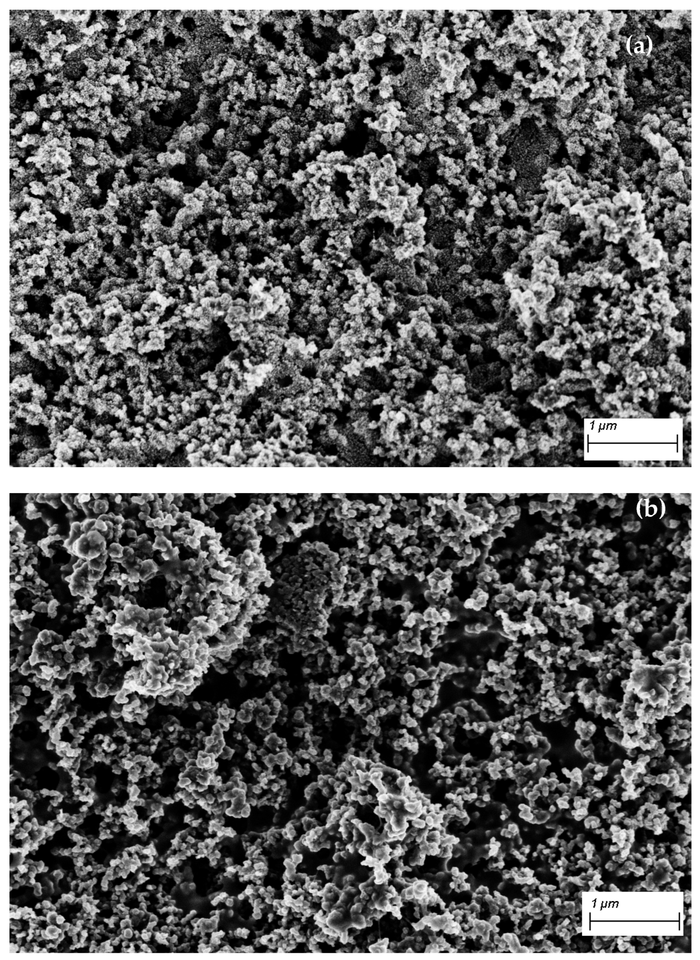
XPS measurements were performed to determine the chemical composition and oxidation state of the Pt nanoparticles on the sputtered electrode (Figure S1), confirming the presence of only metallic Pt species, thus the purity of the coatings. For the observation and comparison of the surface morphology of the sputtered and commercial electrodes, images of the surface were obtained by SEM (Figure 2). The sputtered Pt electrode (PtS_GDE) clearly shows a rough surface formed by nanoparticles (Figure 2a), while the commercial sample (PtCom_GDE) presented a smoother surface as Pt nanoparticles are mixed with the carbon black powder (Figure 2b). In the sputtered sample, all of the Pt nanoparticles are on the electrode surface, potentially increasing Pt exposure to the electrolyte.
The size and nanoparticle distribution of the electrodes were analyzed using TEM images. The diameter of 100 nanoparticles was measured from the images to elaborate the PtS_GDE nanoparticle size statistic size histogram. An average size of around 4 nm was obtained with a narrow size distribution from 2 to 6 nm (Figure 3b) for the PtS_GDE sample, and most parts of the Pt nanoparticles showed a well-defined spherical shape (Figure 3a). High-angle annular dark-field scanning TEM (HAADF-STEM) images reveal that Pt nanoparticles on the PtCom_GDE sample are scattered inside the carbon black powder (Figure 3d), while Pt nanoparticles on PtS_GDE are deposited only on the surface of the carbon black MPL. In the case of the PtS_GDE, as a consequence of the high surface area of the MPL, the thickness is non-homogeneous (Figure 3c).
Finally, the Pt content of both samples was obtained from thermogravimetric analyses. The initial weight loss (approximately 17% between 500 and 590 °C) is related to the presence of PTFE in the carbonaceous substrate. In the range of 590–750 °C (around 81%), the rest of the carbon species are calcinated, and the remaining mass corresponds to Pt, the only compound that is stable at high temperatures. Hence, Pt loading was obtained from the mass at the highest analysis temperature. Two measurements were performed for each electrode, and the results show that PtCom_GDE has a Pt loading of 3.93 ± 1.58 wt% (0.3 mg cm−2) while PtS_GDE contains 1.37 ± 0.29% (0.105 mg cm−2) (Figure 3e). This is a remarkable reduction in the Pt loading of 67% with respect to the 0.3 mg cm−2 Pt/C commercial electrode.

3.2. Electrochemical Characterization

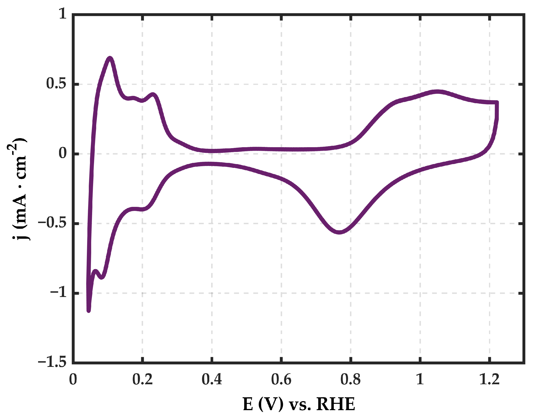
The cyclic voltammogram of the sputtered sample after stabilization in the Ar-saturated 0.5 M H2SO4 electrolyte is depicted in Figure 4. The observed peaks correspond with the reported for polycrystalline Pt with an Hupd region between 0.05 and 0.4 V, followed by the double layer region and, towards more positive potentials, the Pt-oxide formation region. Moving to more negative potential values, the reduction of Pt oxides can be observed in the reserves scan around ca. 0.8 V [33].
To evaluate and compare the HER activity of both electrodes, a potential sweep from 0 V vs. RHE towards cathodic potential values was recorded in the Ar atmosphere. Figure 5 shows the polarization curves where the overpotentials needed to reach a current density value of −10 mA cm2 are the reference for the evaluation of the HER activity of different catalysts [34,35]. As presented in Figure 6, the overpotential for a current density of −10 mA cm2 of the PtCom_GDE sample is 74 mV, while the overpotential at the same current density for the PtS_GDE is 53 mV. These results are preliminary proof that Pt loading can be reduced without compromising the electrode activity towards the HER. Besides, the reduction of the overpotential, when compared to the commercial sample, could be influenced by the fact that in the sputtered electrode, all Pt nanoparticles are placed on the surface in direct contact with the reactant, while in the commercial sample, the Pt active sites can be more difficult to reach since they are mixed with the MPL powder.
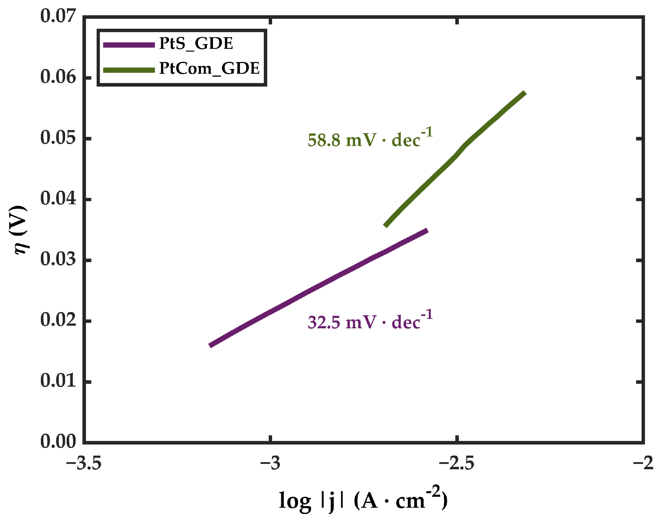
Regarding the kinetic parameters of both electrodes, the Tafel slope for the HER reaction was extracted from the Tafel curves shown in Figure 6. At an acidic pH, the HER occurs through two reaction pathways: Volmer Heyrovsky or Volmer-Tafel. For polycrystalline Pt, the reported values are over 30–40 mV dec−1, which corresponds to the Volmer-Tafel pathway [36,37]. Tafel slopes for PtS_GDE and PtCom_GDE are 32.8 and 58.8 mV dec−1, respectively, which are in concordance with the reported values for polycrystalline Pt. In the case of the PtCom_GDE, the slope is slightly higher than for PtS_GDE, meaning that the HER is happening at a slower pace in the case of the commercial sample. As Pt nanoparticles are mixed with the carbon MPL, this could hinder the access of the reactants to the active sites and the release of gas bubbles, slowing the reaction rate [25].
Since the results of the ex-situ tests indicated that the Pt sputtering electrodes performed better than the commercial ones, in situ tests in electrolysis cells were conducted. Measurements were carried out as described in Section 2.3 in a self-designed single cell. After the 24 h preconditioning, polarization V-i curves were performed every 24 h, applying stationary current densities of 1.5 A cm−2 between each curve. Figure 7 shows the recorded V-i curves at 0 h, 24 h, 72 h, and 168 h for PtCom_GDE (Figure 7a) and PtS_GDE (Figure 7b).
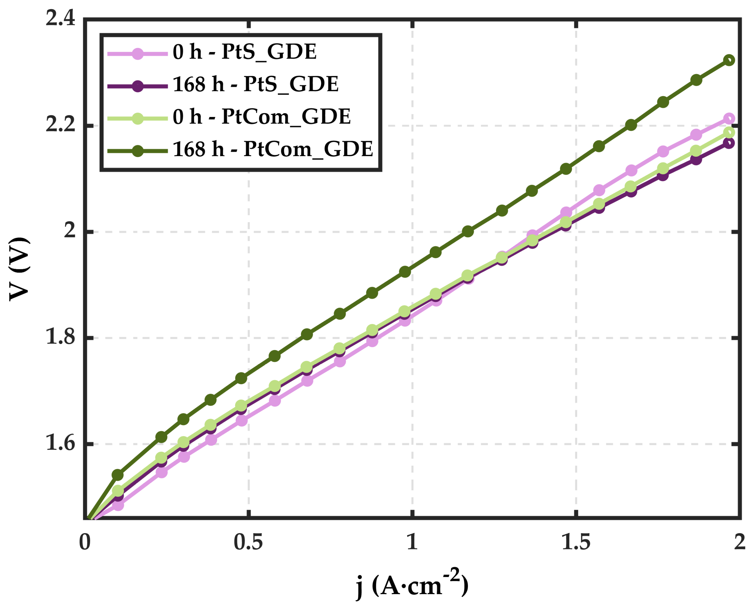
When using the PtCom_GDE sample as the cathode, t = 0 h curve, the potential corresponding to a current density of 1 A cm−2 is 1.85 V. This potential value increases up to 1.93 V after 168 h of operation. For the PtS_GDE, the initial t = 0 h V-i curve shows slightly higher voltages at the second half of the current density sweep compared to the rest of the polarization curves. Nevertheless, the voltage stabilizes completely after the first polarization curve. Figure 8 compares the V-i curves at 0 h and 168 h for both samples, demonstrating that, under the same conditions, the PtS_GDE electrode is more stable with time than the PtCom_GDE sample. Both start with 1.85 V at 1 A cm−2; however, at t = 168 h, the potential value is maintained nearly the same for the PtS_GDE, whereas for the PtCom_GDE electrode, the potential has increased over time.
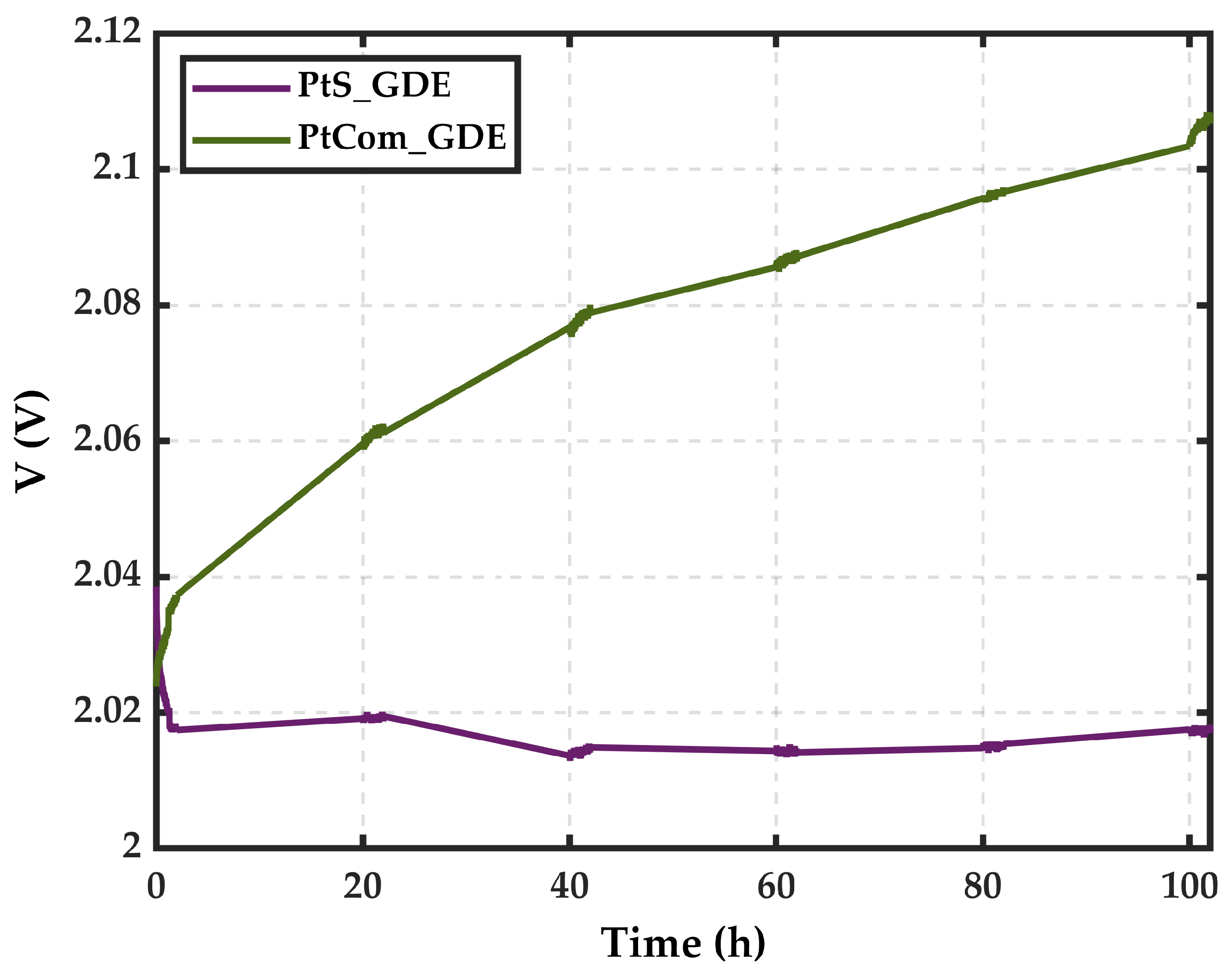
This voltage variation is further observed in stationary current measurements. To estimate the degradation rate, operation potentials at stationary current densities were measured for 2 h every 20 h over a total period of 100 h. From the slope of the curve, the degradation rate can be extracted. Figure 9. presents the V vs. t graphic of PtCom_GDE and PtS_GDE. The same tendencies as seen in V-i curves are observed, hence proving the stability of the PtS_GDE. The slope extracted from the linear regression of the PtCom_GDE measurements corresponds to a degradation rate of 700 µV h−1 at an operation current density of 1.5 A cm−2. Meanwhile, the degradation rate for the PtS_GDE is completely negligible, as the line is almost flat.
Summarizing all the results, it is evident that reducing the amount of Pt is not hindering the cell performance. In fact, using MSGA as a deposition method could enhance cell performance not only because all of the catalytic material is on the MPL surface but also because the deposited nanoparticles could be better attached to the surface as a consequence of an adhesion improvement. One of the major issues of Pt/C catalysts is the lack of adhesion and nanoparticle agglomeration, which negatively impacts performance [38,39].

4. Conclusions

Pt-sputtered electrodes have been successfully developed by gas aggregation magnetron sputtering to study the effect of Pt loading reduction in the performance of a PEM single cell. The surface morphology and composition study confirmed that the catalytic surface was formed by spherical 4 nm pure Pt nanoparticles. The achievement of a 67% reduction in Pt compared with a 0.3 mg cm−2 Pt/C commercial electrode without compromising cell performance content. Although the conditions used in this work need to be transferred and adapted to a magnetron sputtering process, this work proves that magnetron sputtering is a promising method to precisely reduce PGM loadings. Finally, from the obtained results, two main conclusions can be drawn:
  • The amount of Pt is not directly related to an improvement in cell performance. The exposition of Pt active sites seems to be much more relevant than the Pt present in the catalytic coating.
  • MSGA is confirmed as a practical and feasible manufacturing method for developing Pt HER electrodes. This technique successfully produces effective, stable, and effective electrodes in a step process, directly depositing pure Pt nanoparticles on the GDL.
Considering the obtained results, it can be confirmed that magnetron sputtering is a feasible manufacturing method for HER low Pt loading electrodes, enabling the reduction of Pt without worsening cell stability or affecting performance. Therefore, magnetron sputtering technology could be a promising technique for the large-scale production of competitive PEMWE electrodes.

Supplementary Materials

The following supporting information can be downloaded at: https://www.mdpi.com/article/10.3390/coatings14070868/s1, Figure S1. XPS Spectrum of the Pt 4f core-level region of PtS_GDE Pt species.

Author Contributions

Conceptualization, A.V., E.G.-B., L.V.B. and S.R.; methodology, A.V., S.R. and A.A.; validation, A.V. and A.A.; formal analysis, A.V.; investigation, A.V.; data curation, A.A. and A.V.; writing—original draft preparation, A.V.; writing—review and editing, A.V., E.G.-B. and L.V.B.; visualization, A.V.; supervision, E.G.-B. and L.V.B.; project administration, E.G.-B.; funding acquisition, E.G.-B. All authors have read and agreed to the published version of the manuscript.

Funding

This work was supported by the H2PLAN project funded by MCIN and Basque Government with funding from European Union NextGenerationEU (PRTR-C17.I1). Spanish grants PID2020-116712RB-C21 and TED2021-131033B–I00 from MCIN/AEI/10.13039/501100011033 are also acknowledged.

Institutional Review Board Statement

Not applicable.

Informed Consent Statement

Not applicable.

Data Availability Statement

Data are contained within the research article.

Acknowledgments

The author would like to acknowledge the contribution of Ion Alberdi to the design and assembly of the PEM single cell.

Conflicts of Interest

The authors declare no conflicts of interest.

References

  1. Baykara, S.Z. Hydrogen as fuel: A critical technology? Int. J. Hydrogen Energy 2005, 30, 545–553. [Google Scholar] [CrossRef]
  2. Wang, Y.; Pang, Y.; Xu, H.; Martinez, A.; Chen, K.S. PEM Fuel cell and electrolysis cell technologies and hydrogen infrastructure development—A review. Energy Environ. Sci. 2022, 15, 2288–2328. [Google Scholar] [CrossRef]
  3. Wang, T.; Cao, X.; Jiao, L. PEM water electrolysis for hydrogen production: Fundamentals, advances, and prospects. Carbon Neutrality 2022, 1, 1–19. [Google Scholar] [CrossRef]
  4. Ayers, K.E.; Renner, J.N.; Danilovic, N.; Wang, J.X.; Zhang, Y.; Maric, R.; Yu, H. Pathways to ultra-low platinum group metal catalyst loading in proton exchange membrane electrolyzers. Catal. Today 2016, 262, 121–132. [Google Scholar] [CrossRef]
  5. El-Shafie, M. Hydrogen production by water electrolysis technologies: A review. Results Eng. 2023, 20, 101426. [Google Scholar] [CrossRef]
  6. Kamaroddin, M.F.A.; Sabli, N.; Abdullah, T.A.T.; Siajam, S.I.; Abdullah, L.C.; Jalil, A.A.; Ahmad, A. Membrane-Based Electrolysis for Hydrogen Production: A Review. Membranes 2021, 11, 810. [Google Scholar] [CrossRef]
  7. Hancke, R.; Holm, T.; Ulleberg, Ø. The case for high-pressure PEM water electrolysis. Energy Convers. Manag. 2022, 261, 115642. [Google Scholar] [CrossRef]
  8. Grigoriev, S.A.; Fateev, V.N.; Bessarabov, D.G.; Millet, P. Current status, research trends, and challenges in water electrolysis science and technology. Int. J. Hydrogen Energy 2020, 45, 26036–26058. [Google Scholar] [CrossRef]
  9. Carmo, M.; Fritz, D.L.; Mergel, J.; Stolten, D. A comprehensive review on PEM water electrolysis. Int. J. Hydrogen Energy 2013, 38, 4901–4934. [Google Scholar] [CrossRef]
  10. Hassan, N.S.; Jalil, A.A.; Rajendran, S.; Khusnun, N.F.; Bahari, M.B.; Johari, A.; Kamaruddin, M.J.; Ismail, M. Recent review and evaluation of green hydrogen production via water electrolysis for a sustainable and clean energy society. Int. J. Hydrogen Energy 2024, 52, 420–441. [Google Scholar] [CrossRef]
  11. Tang, H.; Peng, Z.; Tian, R.; Ye, L.; Zhang, J.; Rao, M.; Li, G. Platinum-Group Metals: Demand, Supply, Applications and Their Recycling from Spent Automotive Catalysts. J. Environ. Chem. Eng. 2023, 11, 110237. [Google Scholar] [CrossRef]
  12. Villamayor, A.; Galyamin, D.; Barrio, L.V.; Berasategui, E.G.; Rojas, S. Highly active ultralow loading Pt electrodes for hydrogen evolution reaction developed by magnetron sputtering. Int. J. Hydrogen Energy 2024, 64, 50–57. [Google Scholar] [CrossRef]
  13. Durst, J.; Simon, C.; Hasché, F.; Gasteiger, H.A. Hydrogen Oxidation and Evolution Reaction Kinetics on Carbon Supported Pt, Ir, Rh, and Pd Electrocatalysts in Acidic Media. J. Electrochem. Soc. 2015, 162, F190–F203. [Google Scholar] [CrossRef]
  14. Bernt, M.; Siebel, A.; Gasteiger, H.A. Analysis of Voltage Losses in PEM Water Electrolyzers with Low Platinum Group Metal Loadings. J. Electrochem. Soc. 2018, 165, F305–F314. [Google Scholar] [CrossRef]
  15. Zhang, Z.; Baudy, A.; Testino, A.; Gubler, L. Cathode Catalyst Layer Design in PEM Water Electrolysis toward Reduced Pt Loading and Hydrogen Crossover. ACS Appl. Mater. Interfaces 2024, 16, 18. [Google Scholar] [CrossRef] [PubMed]
  16. Liang, X.; Wang, L.; Hamdy, M.S.; Zhang, K.; Sun, K.; Wang, Y.; Xie, Z.; Wu, Q.; Bai, X.; Chen, H.; et al. Status and perspectives of key materials for PEM electrolyzer. Nano Res. Energy 2022, 1, 9120032. [Google Scholar] [CrossRef]
  17. Hrbek, T.; Kúš, P.; Kosto, Y.; Rodríguez, M.G.; Matolínová, I. Magnetron-sputtered thin-film catalyst with low-Ir-Ru content for water electrolysis: Long-term stability and degradation analysis. J. Power Sources 2023, 556, 232375. [Google Scholar] [CrossRef]
  18. Nefedkin, S.I.; Ryabukhin, A.V.; Eletskikh, V.E.; Boldin, R.G.; Mikhnevich, V.D.; Klimova, M.A. Magnetron Technology for Manufacturing of Electrodes for Electrolyzers with Proton-Exchange Membranes. Russ. J. Electrochem. 2024, 60, 200–210. [Google Scholar] [CrossRef]
  19. Jiménez, P.C.; Sievers, G.; Quade, A.; Brüser, V.; Pittkowski, R.K.; Arenz, M. Gas diffusion electrode activity measurements of iridium-based self-supported catalysts produced by alternated physical vapour deposition. J. Power Sources 2023, 569, 232990. [Google Scholar] [CrossRef]
  20. Bernsmeier, D.; Selve, S.; Nissen, J.; Maticiuc, N.; Ibaceta-Jaña, J.; Szyszka, B.; Muydinov, R. Gas Flow Sputtering of Pt/C Films and Their Performance in Electrocatalytic Hydrogen Evolution Reaction. ChemPhysChem 2023, 24, e202200650. [Google Scholar] [CrossRef]
  21. Ivanova, N.A.; Kukueva, E.V.; Shapir, B.L.; Kudinova, E.S.; Akel’kina, S.V.; Alekseeva, O.K. Russian Text © The Author(s), 2020, published in Rossiiskie Nanotekhnologii. Nanotechnol. Russ. 2020, 15, 741–748. [Google Scholar] [CrossRef]
  22. Ivanova, N.A.; Alekseeva, O.K.; Fateev, V.N.; Shapir, B.L.; Spasov, D.D.; Nikitin, S.M.; Presnyakov, M.Y.; Kolobylina, N.N.; Soloviev, M.A.; Mikhalev, A.I.; et al. Activity and durability of electrocatalytic layers with low platinum loading prepared by magnetron sputtering onto gas diffusion electrodes. Int. J. Hydrogen Energy 2019, 44, 29529–29536. [Google Scholar] [CrossRef]
  23. Alekseeva, O.K.; Mikhalev, A.I.; Lutikova, E.K.; Porembsky, V.I.; Presnyakov, M.Y.; Fateev, V.N.; Shapir, B.L.; Grigoriev, S.A. Structural and Electrocatalytic Properties of Platinum and Platinum-Carbon Layers Obtained by Magnetron-Ion Sputtering. Catalysts 2018, 8, 665. [Google Scholar] [CrossRef]
  24. Alekseeva, O.K.; Lutikova, E.K.; Markelov, V.V.; Porembsky, V.I.; Fateev, V.N. Stationary and Pulsed Magnetron Sputtering Technologies for Protective/Catalyst Layer Production for PEM Systems. Int. J. Electrochem. Sci. 2018, 13, 797–811. [Google Scholar] [CrossRef]
  25. Kang, Z.; Yang, G.; Mo, J.; Li, Y.; Yu, S.; Cullen, D.A.; Retterer, S.T.; Toops, T.J.; Bender, G.; Pivovar, B.S.; et al. Novel thin/tunable gas diffusion electrodes with ultra-low catalyst loading for hydrogen evolution reactions in proton exchange membrane electrolyzer cells. Nano Energy 2018, 47, 434–441. [Google Scholar] [CrossRef]
  26. Fedotov, A.A.; Grigoriev, S.A.; Lyutikova, E.K.; Millet, P.; Fateev, V.N. Characterization of carbon-supported platinum nano-particles synthesized using magnetron sputtering for application in PEM electrochemical systems. Int. J. Hydrogen Energy 2013, 38, 426–430. [Google Scholar] [CrossRef]
  27. Huttel, Y. (Ed.) Gas-Phase Synthesis of Nanoparticles; Wiley: Hoboken, NJ, USA, 2017. [Google Scholar]
  28. Martínez, L.; Díaz, M.; Román, E.; Ruano, M.; Llamosa P, D.; Huttel, Y. Generation of nanoparticles with adjustable size and controlled stoichiometry: Recent advances. Langmuir 2012, 28, 11241–11249. [Google Scholar] [CrossRef] [PubMed]
  29. Popok, V.N.; Kylián, O. Gas-Phase Synthesis of Functional Nanomaterials. Appl. Nano 2020, 1, 25–58. [Google Scholar] [CrossRef]
  30. Acsente, T.; Dobrea, M.C.; Satulu, V.; Bita, B.; Dinescu, G. Operation of a magnetron sputtering gas aggregation cluster source in a plasma jet regime for synthesis of core–shell nanoparticles. J. Phys. D Appl. Phys. 2020, 54, 02LT01. [Google Scholar] [CrossRef]
  31. Kratochvíl, J.; Kuzminova, A.; Kylián, O.; Biederman, H. Comparison of magnetron sputtering and gas aggregation nanoparticle source used for fabrication of silver nanoparticle films. Surf. Coatings Technol. 2015, 275, 296–302. [Google Scholar] [CrossRef]
  32. Anantharaj, S.; Noda, S. iR drop correction in electrocatalysis: Everything one needs to know! J. Mater. Chem. A 2022, 10, 9348–9354. [Google Scholar] [CrossRef]
  33. Chen, D.; Tao, Q.; Liao, L.W.; Liu, S.X.; Chen, Y.X.; Ye, S. Determining the Active Surface Area for Various Platinum Electrodes. Electrocatalysis 2011, 2, 207–219. [Google Scholar] [CrossRef]
  34. Raveendran, A.; Chandran, M.; Dhanusuraman, R. A comprehensive review on the electrochemical parameters and recent material development of electrochemical water splitting electrocatalysts. RSC Adv. 2023, 13, 3843–3876. [Google Scholar] [CrossRef]
  35. Wei, C.; Rao, R.R.; Peng, J.; Huang, B.; Stephens, I.E.L.; Risch, M.; Xu, Z.J.; Shao-Horn, Y. Recommended Practices and Benchmark Activity for Hydrogen and Oxygen Electrocatalysis in Water Splitting and Fuel Cells. Adv. Mater. 2019, 31, e1806296. [Google Scholar] [CrossRef]
  36. Shinagawa, T.; Garcia-Esparza, A.T.; Takanabe, K. Insight on Tafel slopes from a microkinetic analysis of aqueous electrocatalysis for energy conversion. Sci. Rep. 2015, 5, 13801. [Google Scholar] [CrossRef]
  37. Dubouis, N.; Grimaud, A. The hydrogen evolution reaction: From material to interfacial descriptors. Chem. Sci. 2019, 10, 9165–9181. [Google Scholar] [CrossRef]
  38. Pu, Z.; Amiinu, I.S.; Kou, Z.; Li, W.; Mu, S. RuP2-Based Catalysts with Platinum-like Activity and Higher Durability for the Hydrogen Evolution Reaction at All pH Values. Angew. Chem. Int. Ed. 2017, 56, 11559–11564. [Google Scholar] [CrossRef]
  39. Liu, Y.; Mustain, W.E. Evaluation of tungsten carbide as the electrocatalyst support for platinum hydrogen evolution/oxidation catalysts. Int. J. Hydrogen Energy 2012, 37, 8929–8938. [Google Scholar] [CrossRef]
Figure 1. Scheme of the PEM single-cell components.
Coatings 14 00868 g001
Figure 2. SEM images of (a) PtS_GDE and (b) PtCom_GDE.
Coatings 14 00868 g002
Figure 3. STEM images of (a) PtS_GDE, (b) size distribution histogram and cross-section colored HAAF-STEM images of (c) PtS_GDE and (d) PtCom_GDE and (e) TGA measurements of PtS_GDE.
Coatings 14 00868 g003
Figure 4. Cyclic voltammetry of PtS_GDE.
Coatings 14 00868 g004
Figure 5. LSV curves of PtS_GDE and PtCom_GDE in an Ar-saturated 0.5 M H2SO4 solution.
Coatings 14 00868 g005
Figure 6. Tafel plots of PtS_GDE and PtCom_GDE.
Coatings 14 00868 g006
Figure 7. Polarization V-i curves at t 0 h, 24 h, 72 h, and 168 h of (a) PtCom_GDE and (b) PtS_GDE.
Coatings 14 00868 g007
Figure 8. Comparison of polarization V-i curves at t 0 h and 168 h of PtCom_GDE and PtS_GDE.
Coatings 14 00868 g008
Figure 9. Comparison of voltage evolution with time of both samples.
Coatings 14 00868 g009
Disclaimer/Publisher’s Note: The statements, opinions and data contained in all publications are solely those of the individual author(s) and contributor(s) and not of MDPI and/or the editor(s). MDPI and/or the editor(s) disclaim responsibility for any injury to people or property resulting from any ideas, methods, instructions or products referred to in the content.