Article

Thermodynamic Analysis of Typical Alloy Oxidation and Carburization in High-Temperature CO2 Atmosphere

State Key Laboratory of Advanced Nuclear Energy Technology, Nuclear Power Institute of China, Chengdu 610213, China
Coatings 2024, 14(7), 869; https://doi.org/10.3390/coatings14070869
Submission received: 8 June 2024 / Revised: 30 June 2024 / Accepted: 8 July 2024 / Published: 11 July 2024

Abstract

:
The corrosion of structural materials is a crucial issue of the application of supercritical carbon dioxide in the Brayton power cycle system. The oxidation and carburization behaviors of typical alloy materials in high-temperature CO2 environments are studied based on thermodynamic analysis technology, including the analysis of the oxidation and carburization performance of the CO2 atmosphere as well as the corrosion behaviors of alloy elements under 500 °C, 600 °C, and 650 °C. In addition, the oxide film characteristics of T91 and 800H alloys, including phase composition and morphology structure, are studied at 500 °C and 650 °C. Research has found that for the T91, FeCr2O4 and Fe3O4 can form a continuous oxide film layer with coverage and SiO2, VO, and MnCr2O4 oxides are mainly in the inner layer of the oxide film. For the 800H, Cr2O3 and MnCr2O4 can form flakes of oxide film layers, while Al2O3, TiO2, and SiO2 are distributed as scattered grains near the interface between the oxide film and the matrix material. Both T91 and 800H will produce chromium carbides, which will reduce the toughness of the material.

1. Introduction

High-temperature CO2, especially supercritical CO2 (S-CO2), has a wide range of applications because of its unique physical and chemical properties. The S-CO2 Brayton power cycle system is the most typical application example [1]. At present, materials selection in an S-CO2 environment and the corrosion mechanisms of structural materials are the key issues in the design and development of the S-CO2 advanced cycle system [2,3,4]. Prior studies have conducted corrosion test analysis on various typical materials, including ferritic steels, austenitic steels, and nickel-based alloys, and have roughly explored their corrosion resistance characteristic and corrosion law [5,6,7,8,9,10]. The corrosion test results indicate that T91 (ferritic steel) and 800H (austenitic steel) are important candidate materials in the S-CO2 Brayton power cycle system. However, it is worth noting that relying solely on corrosion testing methods to explore all issues is somewhat challenging, mainly due to the high time cost consumption. Therefore, theoretical simulations or predictions are essential, such as thermodynamic theory.
Thermodynamic principles can be used to judge and analyze the corrosion behavior characteristics of materials from the source of the corrosion, which has a good guiding role in material selection and corrosion resistance prediction. Several commercial thermodynamic and kinetic software programs, such as Thermo-calc, DICTRA, HSC, JMatPro, and Factstage, have been employed to predict corrosion or analyze the S-CO2 environments. Their specific contributions include predicting the phase evolution at elevated temperatures [11], calculating the equilibrium oxygen partial pressure of the S-CO2 phase [12] and metal oxides [13], showing how element activity is affected by alloy composition [14,15], drawing the oxides/carbide stability diagram [13], confirming the activity of carbon for carbide precipitation [15], and providing the phase diagram as a function of temperature or composition [16,17].
From a thermodynamic perspective, the oxidation and carburization behavior of alloy materials is mainly influenced by two aspects: one is the oxygen partial pressure and carbon activity in the environment, and the other is the equilibrium oxygen partial pressure and carbon activity corresponding to the oxidation and carburization of alloy elements in the alloy material. Herein, oxygen partial pressure refers to the pressure at which individual oxygen is present in a gaseous environment, and the higher the oxygen partial pressure, the stronger the oxidizing ability of the gaseous environment. Carbon activity refers to the level of carbon activity in the environment, and the higher the carbon activity, the stronger the ability of the environment to carbonize and contact materials. The equilibrium oxygen partial pressure refers to the oxygen partial pressure corresponding to a chemical reaction in equilibrium. When the oxygen partial pressure in the environment is greater than the equilibrium oxygen partial pressure of the oxide of the alloy element in the material at that temperature, the alloy element will oxidize and generate the corresponding oxide. When the oxygen partial pressure in the environment is less than the equilibrium oxygen partial pressure of the oxide at that temperature, the oxide cannot form. The formation of carbides is also based on this principle. For example, Young [18] analyzed the corrosion characteristics of typical materials in carbon dioxide through thermodynamical methods and elucidated the oxidation behavior and carbonization principle of the materials.
This article will delve into the oxidation and carburization behavior of alloy materials in a high-temperature CO2 atmosphere based on thermodynamic analysis methods, analyze the oxygen partial pressure and carbon activity of the CO2 environment, explore the oxidation and carburization behavior of typical steel materials (including ferritic steel and austenitic steel), and analyze the carburization behavior and composition of the inner layer of the oxide film under different temperatures of 500 °C, 600 °C, and 650 °C. Based on the thermodynamic analysis method, oxidation and carburization behavior analysis is also conducted on T91 and 800H alloys at 500 °C and 650 °C, respectively.

2. Analytic Methods

Based on thermodynamic calculations of the oxygen partial pressure and carbon activity formed by the decomposition of CO2, the oxidation and carburization performance of the CO2 atmosphere is analyzed. For oxidation research into typical steel materials, including ferritic steels and austenitic steels, the formation reactions of stable oxides for the main constituent alloy elements (Fe, Cr, Ni, Al, Si, Mn, etc.) are studied through the Gibbs free energy. Similarly, thermodynamic calculations are also performed on the carbonization reactions of these alloy elements, and the corresponding standard Gibbs free energy for the carbonization reaction is obtained. By comparing the oxygen partial pressure and carbon activity required for the oxidation and carbonization of the alloy elements with the oxygen partial pressure and carbon activity under a CO2 environment, the possibility of oxidation and carburization of ferritic steel and austenitic steel in a CO2 environment under 500 °C, 600 °C, and 650 °C is analyzed. For calculating the carbon activity required for the carbonization reaction of Cr element in alloys, the thermodynamic software Thermocalc-2022b and the basic substance database provided by the software were used, respectively.
During oxidation behavior analyses of alloys in a CO2 environment, the pressure condition chosen here is the commonly used pressure value in the S-CO2 Brayton cycle system, which is about 20 MPa. At the same time, a comparative analysis is conducted on the effect of pressure on alloy oxidation by selecting different pressure values (0, 10, and 20 MPa). The selection of temperature range from 500 °C to 650 °C in thermodynamic analysis is also based on the commonly used temperature range in the S-CO2 Brayton power cycle system.
During thermodynamic calculation, T91 and 800H alloys, which are candidate materials in the S-CO2 Brayton power cycle system, are selected as typical representatives of ferritic steel and austenitic steel, respectively. The main elemental composition of T91 and 800H alloys are shown in Table 1. Thermodynamic analysis for T91 and 800H alloys is conducted on elements with a mass ratio greater than 0.1 wt% in the alloy, such as Fe, Cr, Ni, Si, Mn, Al, Ti, Mo, and V. The standard Gibbs free energy and equilibrium oxygen partial pressure required for the oxidation reaction of these main constituent elements in T91 and 800H are calculated under 500 °C and 650 °C. By comparing the oxygen partial pressure required for oxidation of T91 and 800H, as well as the equilibrium oxygen partial pressure of the CO2 environment under these temperature conditions, the oxidation behaviors of T91 and 800H in the CO2 environment at 500 °C and 650 °C are analyzed. Schematic diagrams of the oxidation and carburization of T91 and 800H alloys are also made on the basis of the thermodynamic analytic results. For the verification of the thermodynamic analysis results, a comparison was made with the characterization analysis results of corrosion tests of T91 and 800H in the same temperature CO2 environment in the literature.

3. Results and Discussion

3.1. Oxidation Behavior of Alloys in a CO2 Environment

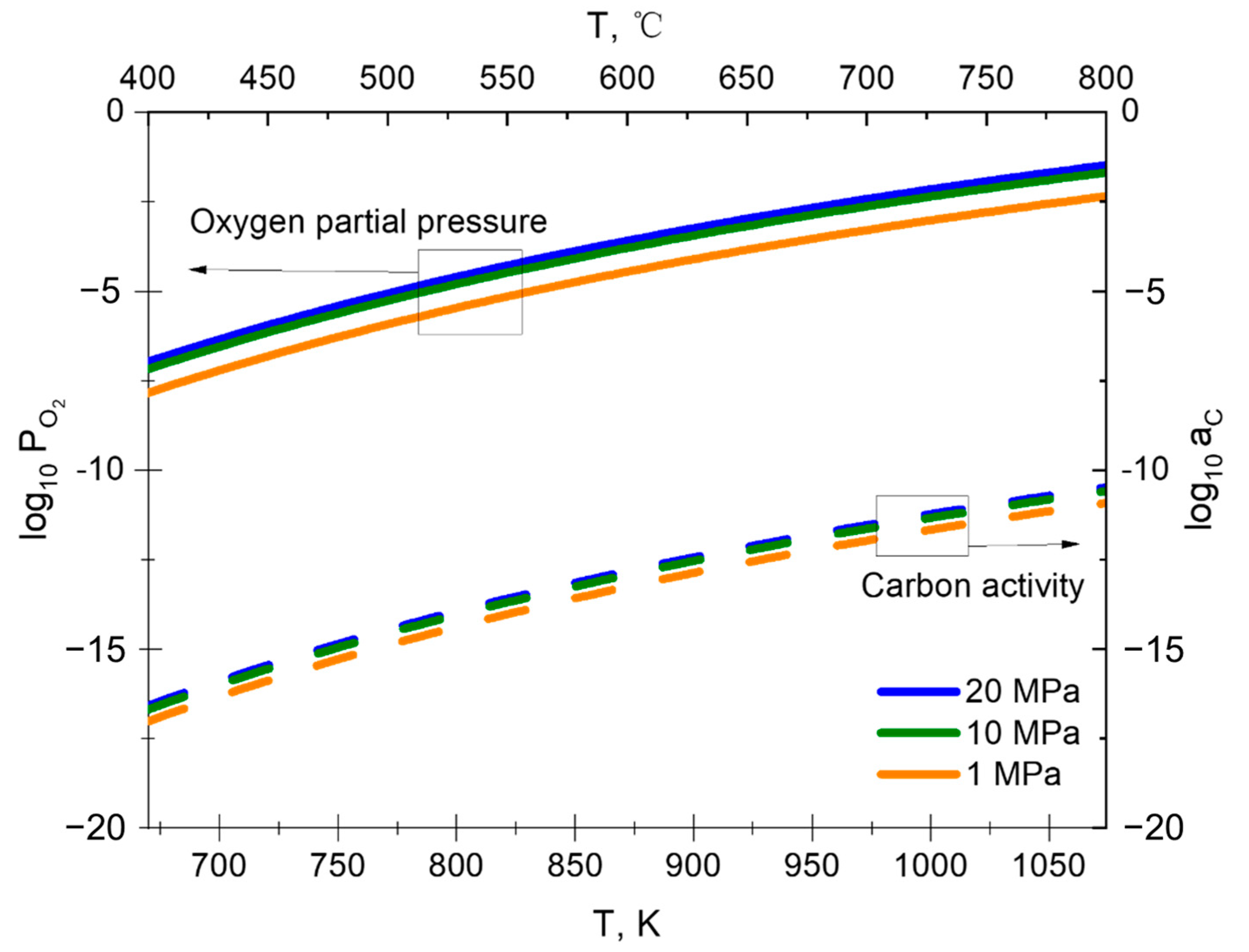
3.1.1. Equilibrium Decomposition of the CO2

When studying the corrosion behavior of steel alloy materials in a CO2 environment, it is necessary to first determine the phase of the oxide film under the corresponding temperature and oxygen partial pressure conditions. In a pure CO2 atmosphere, the oxygen used to drive the growth of oxide films on the material surface comes from the equilibrium decomposition of CO2.
C O 2 g = C O g + 1 / 2 O 2 ( g )
k C O 2 = p O 2 0.5 p C O / p C O 2
l n k C O 2 = G C O 2 0 / R T
In the formula, the oxygen partial pressure p O 2 is an important parameter that affects which kind of oxide film is formed on the material surface. It can be solved by the Equilibrium constant k and the Gibbs free energy ∆G of the CO2 decomposition reaction. From the thermodynamic data handbook [19], the Gibbs free energy of CO2 can be obtained by Equation (4).
G C O 2 0 ( J / m o l ) = 280950 + 85.23 T ( 1 / K )
In Formula (4), G C O 2 0 is the Gibbs free energy of reaction (1) from right to left, T is the temperature, and K is the Kelvin temperature unit.
Assuming that CO2 decomposes on the gas–solid surface of the material, x (x < 1) mol of 1 mol CO2 undergoes decomposition and generates x mol CO and x/2 mol O2. The ambient Total pressure is P, so the calculation of oxygen partial pressure in a CO2 environment can be expressed as follows:
p O 2 = x / 2 ( 1 x + x + x / 2 ) P = x 2 + x P
p C O = 2 x 2 + x P
p C O 2 = 1 x ( 1 x + x + x / 2 ) P = 2 ( 1 x ) 2 + x P
Then, the Equilibrium constant of CO2 can be expressed as,
k C O 2 2 = x / 2 + x P · 2 x / 2 + x P 2 / 2 1 x / ( 2 + x ) 2 P 2 = P x 3 / [ 2 + x 1 x ]
Since x << 1, the above equation can be simplified as,
k C O 2 2 = P x 3 / 2
So
x = ( 2 k C O 2 2 P ) 1 / 3
Therefore, the partial pressure of oxygen in a CO2 atmosphere is a function of temperature (reflected by k C O 2 ) and environmental Total pressure,
p O 2 = ( P k C O 2 2 ) 2 / 3
The partial pressure of oxygen in a CO2 environment at different temperatures and 20 MPa Total pressure is listed in Table 2.

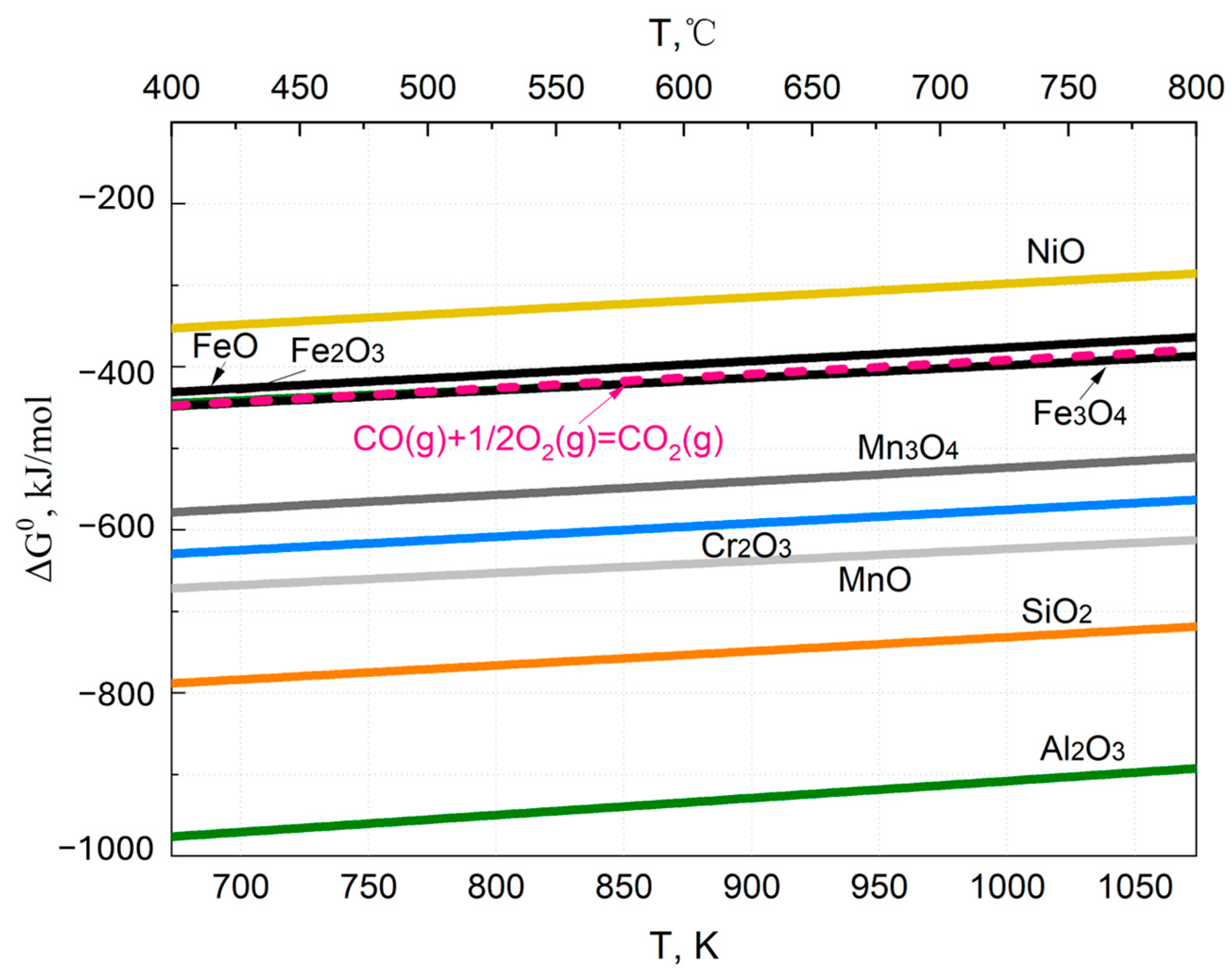
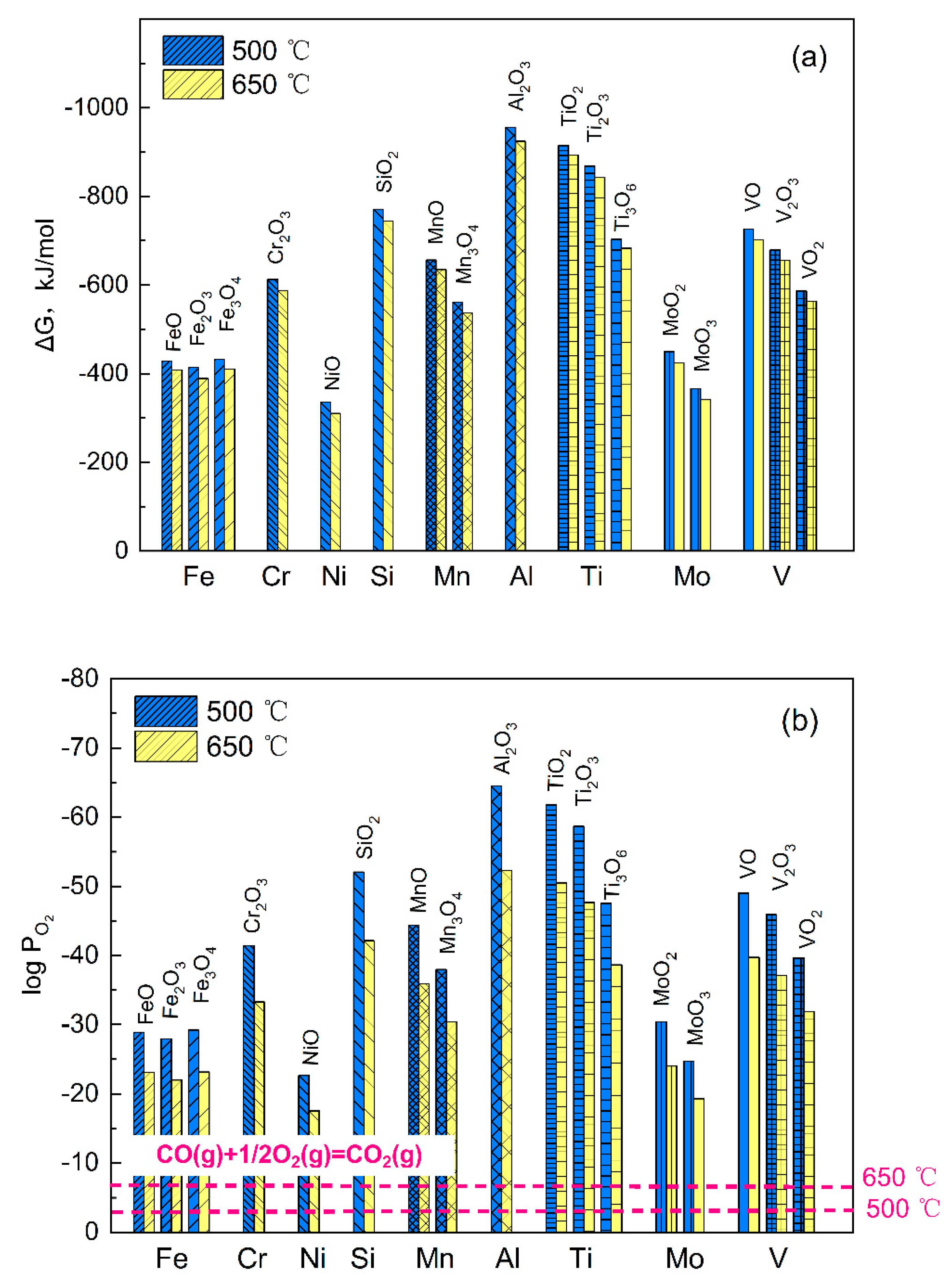
3.1.2. Oxidation of the Alloy

According to thermodynamics, when a material’s surface comes into contact with an oxidizing atmosphere, an oxidation reaction occurs, generating all stable oxides that can exist. The reaction of alloy element M in the material with oxygen to generate oxides can be simply treated as the following reaction equation.
x M s + y / 2 O 2 g = M x O y ( s )
The thermodynamic stability of oxide formation is that the oxide is in the oxygen partial pressure atmosphere, ( p O 2 ) d i s s o c , corresponding to the balance of chemical decomposition (reaction (12) from right to left).
l n k M x O y = l n ( p O 2 ) d i s s o c y / 2 = G M x O y 0 / R T
In the formula, G M x O y 0 is the Gibbs free energy (J mol−1) of reaction (12). It should be noted that this reaction assumes that the activity of a single metal is 1, but for alloys, the activity is usually 0.1–1.
For typical steel materials, including ferritic steel and austenitic steel, the main constituent alloy elements include Fe, Cr, Ni, Al, Si, Mn, etc. The formation reactions of stable oxides corresponding to these alloy elements are mainly shown in Table 3.
The composite oxide formed on the surface of the alloy after oxidation is usually composed of octahedral and tetrahedral oxides, and metal elements such as Fe, Cr, Al, Si, and Mn are filled in the gaps between the tetrahedral and octahedral oxides. Composite oxides usually have high thermodynamic stability, and their Gibbs free energy of formation is usually very low. As long as the corresponding alloy element can form oxides such as C r 2 O 3 , F e 3 O 4 , and M n O , corresponding composite oxides usually can form. So the chemical reactions and Gibbs free energy of the composite oxide are no longer listed here.
Based on Equation (4) and Table 3, the Gibbs free energy of CO2 and various oxides varies with temperature are shown in Figure 1. From Figure 1, it can be seen that Fe oxidation on the material surface will preferentially generate F e 3 O 4 , then F e 2 O 3 and F e O . Moreover, compared to the Gibbs free energy of CO2 decomposition, F e 2 O 3 and FeO have higher Gibbs free energy, making them difficult to form. Figure 1 also shows that the Gibbs free energy of M n O , M n 3 O 4 , C r 2 O 3 , and A l 2 O 3 is lower than that of F e 3 O 4 . If Fe, Cr, Si, Al, and Mn elements coexist during material oxidation, the material will preferentially generate A l 2 O 3 , followed by S i O 2 , M n O , C r 2 O 3 , M n 3 O 4 , and F e 3 O 4 oxides, respectively. In addition, it can be seen from Figure 1 that the Ni element in the material is difficult to oxidize under a CO2 atmosphere, and there will be no NiO present in the oxide film on the surface of the material if free O2 is not formed.
According to Formula (13), the equilibrium oxygen partial pressure generated by oxides can be obtained through Gibbs free energy
l o g 10 p O 2 = 2 G M x O y 0 / 2.303 y R T
Substituting Equation (14a–i) into Equation (15) allows the equilibrium oxygen partial pressure of each oxide decomposition to be solved. The temperature-dependent graph of the equilibrium oxygen partial pressure of the oxide is shown in Figure 2.
From Figure 2, it can be seen that the equilibrium decomposition oxygen partial pressure of CO2 under a pressure of 20 MPa is 20~30 orders of magnitude higher than that of F e 3 O 4 . Therefore, under a CO2 atmosphere of 20 MPa, the oxygen partial pressure on the material surface is sufficient to support the oxidation of Fe, Cr, Al, Mn, and Si to form oxides. Moreover, when alloy elements such as Fe, Cr, Al, Si, and Mn that are prone to forming composite oxides can undergo oxidation, their corresponding composite oxides can usually be oxidized and formed under sufficient elemental composition, such as iron chromium spinel, manganese chromium spinel, etc. The calculated equilibrium oxygen partial pressure data of each oxide decomposition in Figure 2 can also be used for studying the dynamic growth model of oxide films during material oxidation and corrosion processes.
In addition, it should be noted that the main composition of the oxide film formed by material surface oxidation corrosion is not only related to the oxide phase that can be formed in thermodynamics, but also influenced by the proportion of alloy elements in the material. For example, when the proportion of alloy elements in the material is less than a sufficiently low value, such as 0.1 wt%, even though the alloy element can form corresponding oxides from a thermodynamic perspective, the formed oxides cannot form continuous or large areas of oxides in the oxide film due to its small proportion. Therefore, oxides with a proportion of less than a certain value will hardly affect the dynamic growth of the overall oxide film, and microscopic characterization techniques such as TEM are also hard to discover them. When the proportion of alloy elements in the material is greater than a certain large value (such as 1 wt%), if a corresponding stable oxide can be formed, a clear area or even continuous flake of oxide distribution can be formed in the oxide film, which can provide a certain protective effect on the material. This phenomenon can be verified in the microscopic characterization results of various material corrosion tests.

3.2. Thermodynamic Analysis of Alloys Carburization in CO2 Environment

In a high-temperature and high-pressure CO2 environment, the surface of steel materials not only undergoes oxidation reactions to generate various oxides but also exhibits the carburization behavior of alloy elements. Here, we first analyze the carbon activity in the environment and then study the carburization behavior of steel materials.

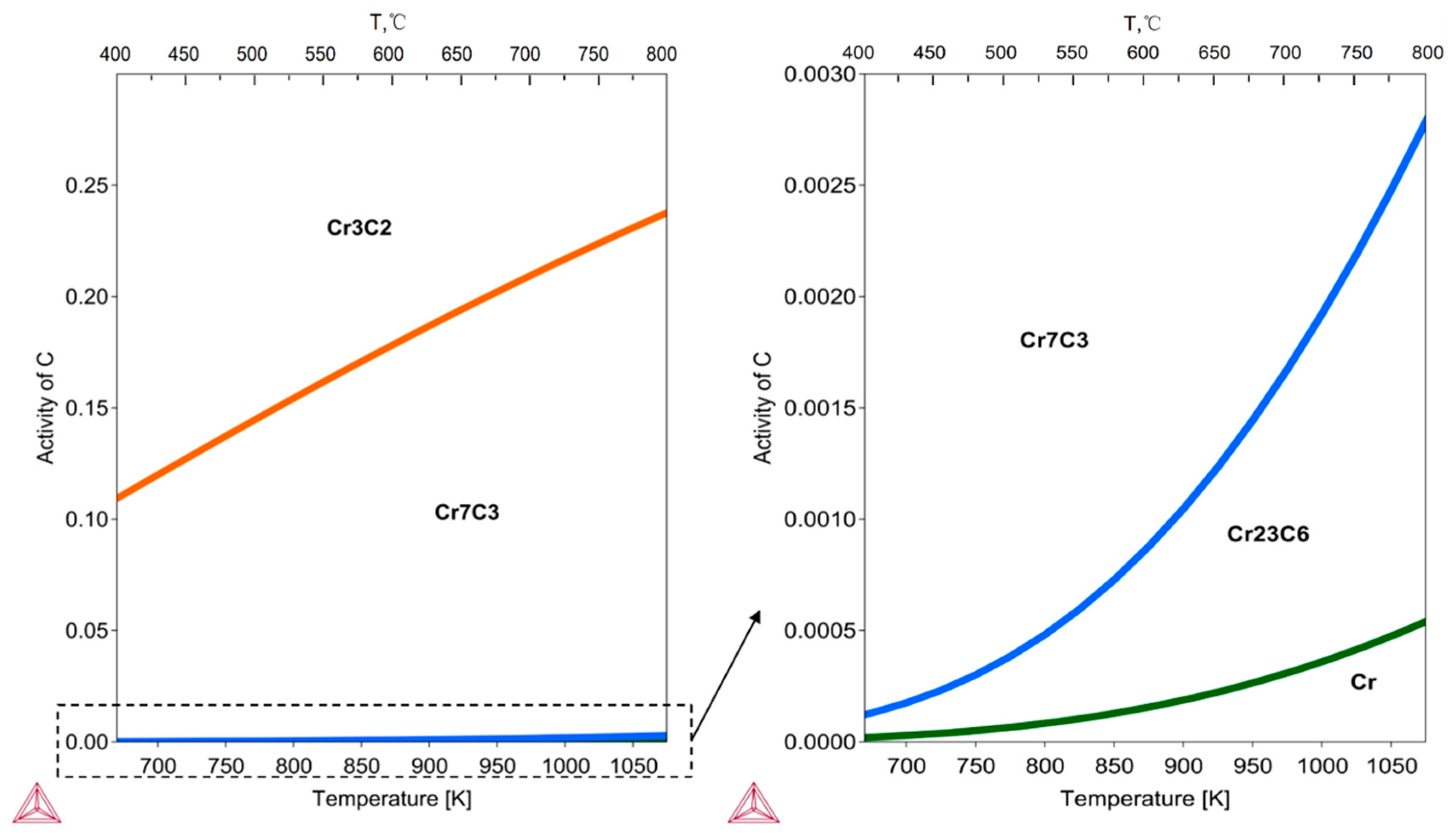
3.2.1. Carbon Activity in the Environment

The C in the CO2 environment mainly comes from the decomposition of CO2 and the formation of CO again, as shown below:
C O g = C s + 1 / 2 O 2 ( g )
G C O 0 ( J / m o l ) = 114400 85.77 T ( 1 / K )
l n k C O = ln p O 2 0.5 a C / p C O = G C O 0 / R T
The partial pressure of Equation (18) can be calculated based on the CO2 equilibrium decomposition in Section 2, ignoring the impact of CO decomposition (where the CO content in the environment is very low) on the partial pressure of the environment.
p C O = ( 2 P k C O 2 ) 2 / 3
Therefore, the carbon activity in the environment is as follows:
a C = p C O p O 2 0.5 e x p ( G C O 0 / R T )
a C = P k C O 2 p O 2 e x p ( G C O 0 / R T )
a C = ( 4 P k C O 2 ) 1 3 e x p ( G C O 0 / R T )
From Equation (21), it can be seen that the carbon activity in the environment is related to the oxygen partial pressure, and the smaller the oxygen partial pressure, the greater the carbon activity. As shown in Figure 3, the oxygen partial pressure and carbon activity in CO2 environments are calculated under different temperature and pressure conditions based on Formulas (11) and (22). From Figure 3, it can be seen that when the pressure increases from 1 MPa to 20 MPa, the oxygen partial pressure and carbon activity in the environment do not change much, and the oxygen partial pressure can increase by about an order of magnitude. However, when the temperature increases from 400 °C to 800 °C, there is a significant order of magnitude increase in both oxygen partial pressure and carbon activity in the environment. Oxygen partial pressure can increase by five orders of magnitude, and carbon activity can increase by seven orders of magnitude.

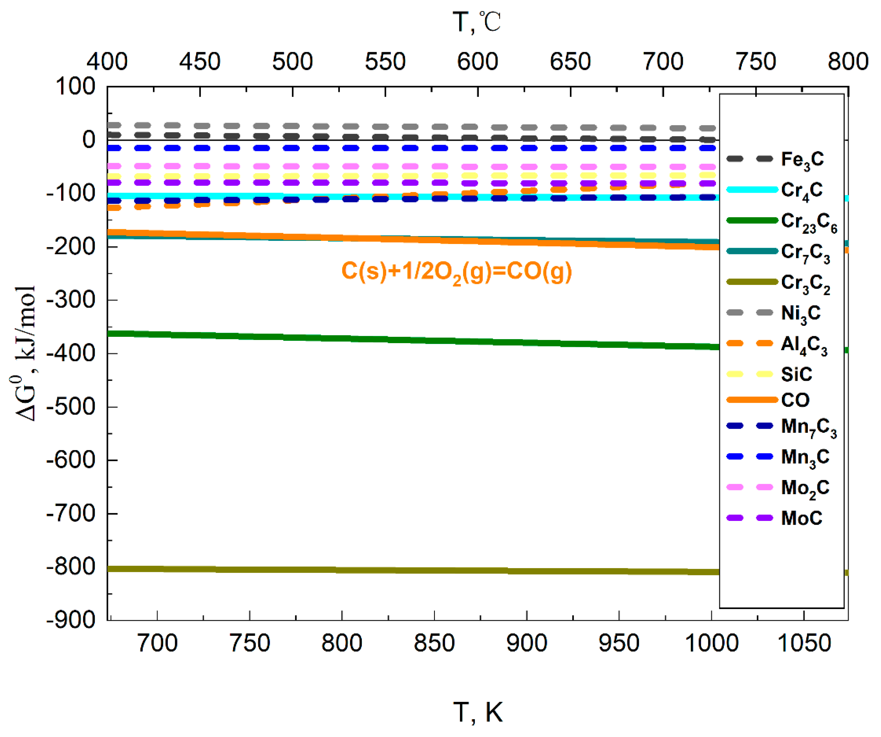
3.2.2. Carburization of Alloy Materials

In high-temperature and high-pressure CO2 environments, steel materials may not only undergo oxidation and corrosion to form an oxide film, but also undergo carburization behavior of alloy elements in the material, forming a carbonized layer in the oxide film. For the main alloying elements of ferritic steel, austenitic steel, such as Fe, Cr, Ni, Al, Si, Mn, and Mo, the possible carburization reactions and generated carbides are shown in Table 4.
According to Formulas (17) and (23a–l), the Gibbs free energy and temperature relationship diagrams for the standard generation of various carbides can be obtained as shown in Figure 4. From Figure 4, it can be seen that compared to Fe, Ni, Al, Si, Mn, and Mo elements, the standard Gibbs free energy of formation of carbides formed by the Cr element is lower, and the chromium carbides generated are more stable. In a CO2 atmosphere, carbides that can be formed are C r 23 C 6 , C r 7 C 3 , and C r 3 C 2 , while other carbides such as C r 4 C and those corresponding to Fe, Ni, Al, Si, Mn, and Mo are difficult to generate. This indicates that the carbides formed by ferritic steel and austenitic steel in CO2 environments are basically chromium carbides.
The thermodynamic software Thermocalc-2022b [23] was used to analyze the Cr-C phase diagram and obtain the carburization of Cr under different temperature and carbon activity conditions, as shown in Figure 5. From Figure 5, it can be seen that the carbides can form within the temperature range of 400 °C to 800 °C and when carbon activity levels are below 0.3 include C r 23 C 6 , C r 7 C 3 , and C r 3 C 2 , which is consistent with the results in Figure 4. Within the temperature range of 400 °C to 800 °C, when the carbon activity is below 0.003, the Cr element is first carbonized to be C r 23 C 6 and then C r 7 C 3 as the carbon activity increases. When the carbon activity in the environment increases to above 0.1–0.3, the Cr element begins to be carbonized as C r 3 C 2 .
Comparing the carbon activity in the CO2 environment in Figure 3 with the equilibrium carbon activity in the chromium carbide in Figure 5, it was found that the carbon activity in the CO2 environment (1 × 10⁻¹⁷~1 × 10⁻¹⁰) is much smaller than the equilibrium activity of Cr to form corresponding carbides (1 × 10⁻⁴~1 × 10⁻¹). Therefore, when the surface of the alloy material comes into direct contact with the CO2 environment, chromium carbides cannot form on its surface. From the corrosion test results of alloy materials in high-temperature and high-pressure CO2 environments, it can be seen from the references [24,25,26] that there is indeed no formation of carbides on the surface of the material’s oxide film. The carbides in the oxide film are formed in the inner layer of the oxide film, which is the interface between the oxide film and the substrate material. The carburization behavior of alloy elements in the inner layer of the oxide film will be specifically discussed in the next section.

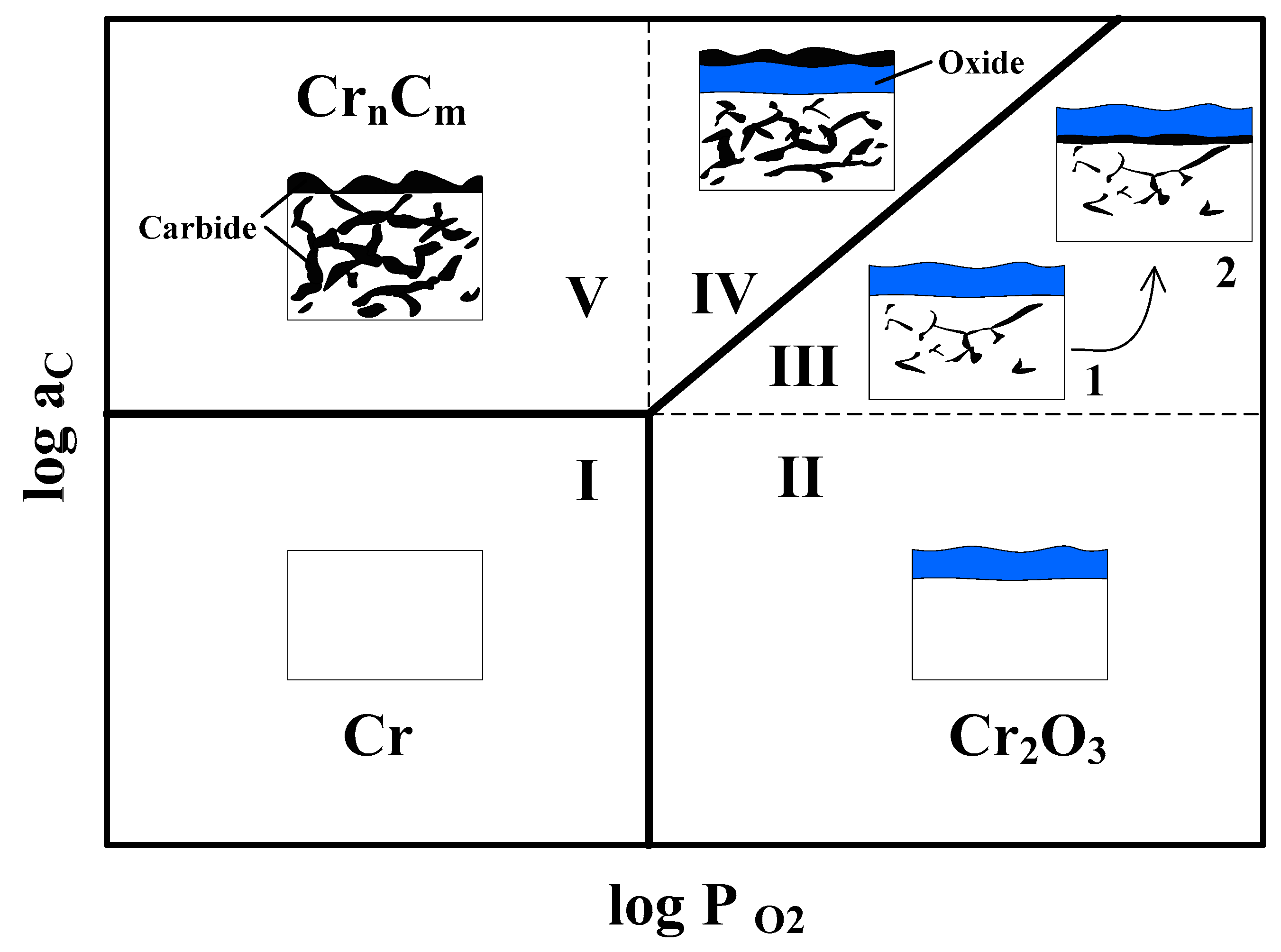
3.3. Decarburization and Carburization Behavior of Alloys

Carbides have poorer toughness compared to oxides, exhibiting significant brittleness [12,13]. For the high-temperature oxidation process of structural materials, people usually do not want obvious carbides to appear inside the oxide film or the matrix material, especially the formation of a carbide layer between the oxide film and the matrix. This is because when a relatively continuous carbonization layer is formed between the oxide film layer and the substrate, the brittleness of the carbonization layer increases the risk of peeling off the oxide film, and the substrate material may lose its protective oxide film on the surface, ultimately leading to bare leakage of the material substrate and entering the rapid corrosion stage again [17,18,19].
The carburization behavior of elements in alloy materials is related to the carbon activity in the environment and the equilibrium decomposition of carbides. When the carbon activity in the environment is much lower than the equilibrium decomposition carbon activity corresponding to carbides, carbides cannot be formed. For example, the surface of the material oxide film mentioned in the previous section will not produce carbides. When the carbon activity in the environment is greater than the equilibrium decomposition carbon activity corresponding to carbides, corresponding carbides will be formed.
For alloy materials with a loose oxide film formed on the surface in a CO2 environment, as shown in Figure 6a, the pore channels of the loose structure in the oxide film provide a free diffusion path for gaseous substances CO2 and CO, making the carbon activity at the oxide/alloy interface consistent with that in the gas layer (1 × 10⁻¹⁷~1 × 10⁻¹⁰), much lower than the equilibrium decomposition carbon activity of chromium carbide (1 × 10⁻⁴~1 × 10⁻¹). Therefore, carburization of chromium cannot happen at the oxide/alloy interface, and due to the lower carbon activity at the oxide/alloy interface than in the material, the alloy material will undergo decarburization behavior, causing the carbides in the original alloy material to decompose.
For alloy materials that can form a dense oxide film on the surface in a CO2 environment, as shown in Figure 6b, the dense oxide film makes it impossible for gaseous substances to reach the surface of the base material freely and quickly, and the oxygen partial pressure in the oxide film will show a decreasing trend from outside to inside due to the thermodynamic equilibrium of the oxide. According to the reverse constraint relationship between carbon activity and oxygen partial pressure in Formula (21), it can be seen that the carbon activity in the oxide film shows an increasing trend, as shown in Figure 6b. When the carbon activity reaches the equilibrium decomposition carbon activity of carbides, carbides form in the inner layer of the oxide film. Due to the fact that the carbon activity at the scale/alloy interface is greater than that in the material, carburization behavior also occurs inside the alloy matrix material, forming dispersed carbides. Alloy materials with good corrosion resistance in general CO2 environments, such as 316 and 800H, will form dense oxide films under high temperature and pressure conditions, and produce carbides in the inner layer of the oxide film [16,27,28,29].
For example, for steel materials containing Cr, a dense Cr2O3 oxide layer can usually be formed on the surface of the material in a CO2 environment, corresponding to the situation shown in Figure 6b. At this point, the inner side of the Cr2O3 oxide layer is in its equilibrium oxygen partial pressure state. By substituting Equations (2) and (21) into the equilibrium oxygen partial pressure of Cr2O3, the carbon activity here can be calculated, and the temperature-dependent curves of the oxygen partial pressure and carbon activity on the inner side of the Cr2O3 oxide layer, as shown in Figure 7, can be obtained. From Figure 7, it can be seen that the theoretical calculation value of carbon activity inside the Cr2O3 oxide layer is large, greater than 1020. Compared with Figure 5, it can be discovered that all Cr elements at this location can be carbonized. When all nearby Cr elements are carbonized, the excess carbon will further form pure carbon. The carbon activity at that location will be determined as one if a pure carbon layer appears, which is the actual carbon activity of the straight line in the dot in Figure 7.
According to the analysis in Section 3.2, Cr can form carbides in CO2 environments comparing with the alloy elements Fe, Cr, Ni, Al, Si, Mn, and Mo. Therefore, this study takes the Cr element as an example to investigate its carburization and oxidation behavior under common application temperatures of 500 °C, 600 °C, and 650 °C. Based on the calculation method of oxygen partial pressure for oxide equilibrium decomposition in Formula (15) and the carbon activity for Cr carbide equilibrium decomposition in Figure 5, the equilibrium carbon activity and equilibrium oxygen partial pressure for Cr carburization and oxidation under different temperature conditions are obtained, as shown in Table 5 and Figure 7.
Figure 8 analyzes the oxidation and carbonization of Cr based on equilibrium oxygen partial pressure and carbon activity, respectively. From Table 5 and Figure 8, it can be seen that temperature has a significant impact on the equilibrium oxygen partial pressure of Cr2O3. When it increases from 500 °C to 650 °C, the equilibrium oxygen partial pressure increases from 10−46.9 Pa to 10−37.7 Pa. However, for Cr carbides, the effect of temperature is not significant. When the temperature increases from 500 °C to 650 °C, the carbon activity of the carbides only increases by less than an order of magnitude. For CO2 environments with high temperatures and pressures ranging from 500 °C to 650 °C, its oxygen partial pressure is greater than 10−10 and the carbon activity is less than 10−10. From Figure 8, it can be seen that this environment is in the Cr2O3 phase region and there is no carbide formation. Only when a dense Cr2O3 oxide film is formed does the equilibrium oxygen partial pressure inside the oxide film change, and carbon activity begins to significantly increase. Then, the environment inside the oxide film enters the CrnCm + Cr2O3 phase zone, and carbides begin to form: first C r 23 C 6 , followed by C r 7 C 3 and C r 3 C 2 . After all the surrounding Cr elements are carbonized, pure carbon begins to form in the inner layer of the Cr2O3 oxide film.
The schematic diagram of the composition of the oxide film on the surface of materials under different environments, represented by the Cr element, is shown in Figure 9. When the environment is in Zone I, the Cr element on the material surface neither oxidizes nor carbonizes. When the environment is in Zone II, all the oxide films on the surface of the material are oxides, without the formation of carbides, such as shown in Refs. [10,30]. When the environment is in Zone III, the material first forms an oxide layer, and then carbides (such as C r 23 C 6 , C r 7 C 3 , and C r 3 C 2 mentioned above) begin to appear in the substrate material and the inner layer of the oxide film, which means that carburization occurs first inside the matrix material and then gradually appears at the oxide/alloy interface (such as shown in Refs. [9,31,32,33]). When the environment is in region IV, carbides first form on the surface of the material, and there are oxides in the inner layer of the carbides. When the environment is in the V region, all Cr elements in the material are carbonized without the formation of Cr oxides. Compared to other regions, materials can form a protective film layer with a certain density and toughness in the II and III regions, which brings anti-corrosion effects to the materials.

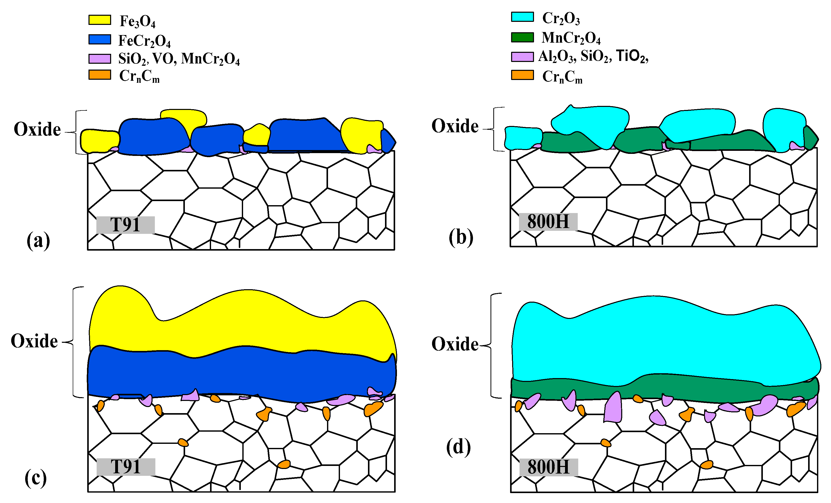
3.4. Oxidation and Carburization Analysis of T91 and 800H

Based on the thermodynamic analysis of alloy material oxidation and carburization discussed above, the oxidation and carburization of ferrite steel material T91 and austenitic steel material 800H were carried out at 500 °C, 650 °C, and 20 MPa pressure conditions, respectively.
As mentioned earlier, the main phase composition of the oxide film formed by material surface oxidation and corrosion is not only related to thermodynamics, but also influenced by the proportion of alloy elements in the material. When the proportion of alloy elements in the material is less than a sufficiently low value, the oxide formed in the oxide film will hardly affect the overall growth of the oxide film and its corrosion resistance. Therefore, thermodynamic analysis is conducted on elements with a mass ratio greater than 0.1 wt%, which is a relatively low proportion in the alloy, such as Fe, Cr, Ni, Si, Mn, Al, Ti, Mo, and V for T91 and 800H alloys.
In order to study the oxidation characteristics of T91 and 800H, Figure 10 calculated and analyzed the Gibbs free energy and equilibrium oxygen partial pressure of their main components undergoing oxidation reactions. Based on Formulas (12) and (13), Figure 10a shows the Gibbs free energy of oxide formation corresponding to the main constituent elements of T91 and 800H at 500 °C and 650 °C, respectively. From Figure 10a, it can be seen that when T91 and 800H first undergo oxidation, they will first form thermally stable oxides such as Al2O3, SiO2, and Cr2O3. For alloy elements with multiple types of corresponding oxides, such as Ti, Mo, Mn, V, and Fe, the oxidation of the alloy will preferentially generate relatively stable oxides such as TiO2, MoO2, MnO, VO, and Fe3O4. By comparing the Gibbs intrinsic energy of the generation of oxides of various alloy elements, it can be seen that the oxidizability of the Ni element is poor. Under the same oxygen environment, it is only possible to generate oxide NiO when all nearby alloy elements are oxidized.
The equilibrium decomposition oxygen partial pressure for the elements in T91 and 800H alloy is calculated based on Formula (15). Figure 10b calculates the equilibrium decomposition oxygen partial pressure according to the oxides listed in Figure 10a and presents the oxygen partial pressure in a CO2 environment under conditions of 20 MPa, 500 °C, and 650 °C. It can be seen from Figure 10b that all oxides can be generated in this environment, and the oxygen partial pressure required for the equilibrium decomposition of Al2O3, TiO2, SiO2, VO, MnO, and Cr2O3 with good stability increases sequentially. When a dense oxide film is formed on the surface of the material, the environmental oxygen partial pressure in the material decreases sequentially from the outer side to the inner side. As the thickness of the dense oxide film gradually increases, the environmental oxygen partial pressure difference in the oxide film gradually increases, resulting in the distribution of oxides Al2O3, TiO2, SiO2, VO, MnO, and Cr2O3 in the oxide film from the inside to out. For Fe3O4 and MoO2, oxides with high equilibrium decomposition oxygen partial pressure will appear on the outer side of the oxide film. If NiO can form, it will be on the outermost side of the oxide film. When the temperature rises from 500 °C to 650 °C, the equilibrium decomposition oxygen partial pressure of each oxide significantly increases by 5–10 orders of magnitude.
The elements in T91 and 800H alloy materials may not only oxidize to form the above oxides, but also form composite oxides. The possible composite oxides formed by the common alloy elements Fe, Cr, Ni, Mn, Si, and Al are also analyzed herein. Table 6 lists the chemical equation and Gibbs free energy generated by each typical composite oxide. Compound oxides with complex decimal separator stoichiometric ratios, such as Fe0.6Cr2.4O4, will not be specifically discussed here.
From Table 6, it can be seen that the Gibbs free energy of the formation of each composite oxide is less than zero, indicating that it can exist stably once formed. According to the chemical reaction equations for the formation of various composite oxides, it can be seen that the formation of some composite oxides requires the formation of corresponding metal oxides, such as NiO, Cr2O3, MnO, etc., before the recombination of metal oxides can occur. Therefore, if the corresponding metal oxide cannot be formed in an oxygen environment, the corresponding composite oxide is also difficult to form. This phenomenon is fully reflected in the Ni element. As mentioned earlier, the oxide of the Ni element is poor, and NiO can only be generated when all alloy elements near the T91 and 800H surfaces are oxidized. Therefore, composite oxides of the Ni element, such as NiFe2O4, NiCr2O4, NiAl2O4, and NiSiO3, are difficult to form by combining metal oxides. Compared with the Ni element, composite oxides corresponding to other metal elements are easier to form, such as FeCr2O4, MnCr2O4, MnAl2O4, and MnSiO3.
According to the Gibbs free energy of the formation of composite oxides under 500 °C and 650 °C conditions in Table 6, it can be seen that MnCrAl2O4 has high thermodynamic stability, and can be formed preferentially compared with FeCr2O4, MnAl2O4, and MnSiO3, followed by FeCr2O4. The thermodynamic stability of MnAl2O4 and MnSiO3 composites is much lower than that of FeCr2O4 and MnCr2O4, and they will the last to be generated.
Based on the above thermodynamic analysis, combined with the alloy element composition of T91 and 800H, the oxidation characteristics and oxide film structure can be predicted as shown in Figure 11.
For T91, in the early stage of oxidation, SiO2, VO, MnO, and Cr2O3 are preferentially formed on the surface of T91. Due to the low content of Si, V, and Mn elements (much less than 0.5 wt%) in T91, Si, V, and Mn elements will be quickly oxidized, and the abundant oxygen will continue to react with the remaining Cr elements to form Cr2O3. At the same time, MnO and Fe react with Cr2O3 to generate MnCr2O4 and FeCr2O4. When the Cr near the surface of T91 is basically consumed, the Fe element begins to be oxidized to generate Fe3O4, as shown in Figure 11a. In the middle stage of oxidation, as the oxygen partial pressure on the material surface decreases with the thickness of the oxide film from the outside to the inside, FeCr2O4 (corresponding to the equilibrium decomposition oxygen partial pressure of Cr2O3) forms in the inner layer of the oxide film and Fe3O4 forms in the outer layer of the oxide film based on the corresponding equilibrium decomposition oxygen partial pressure of each oxide. Moreover, due to the high proportion of Cr and Fe elements, FeCr2O4 and Fe3O4 can form a continuous oxide film layer with coverage, as shown in Figure 11c, which can provide excellent corrosion protection for the T91. For SiO2, VO, and MnCr2O4 oxides, due to their low equilibrium decomposition oxygen partial pressure, their formation position is mainly in the inner layer of the oxide film, and they are scattered in very small grain shapes (due to the small proportion of their elemental composition) near the boundary between the oxide film and the matrix. The schematic diagram of the formation process of T91 oxide film is shown in Figure 11.
The thermodynamic analysis results of the phase composition of the T91 oxide film mentioned above are basically consistent with the TEM, XRD, and other detection results of the oxide film in the literature [3,9,10]. As shown in Figure 12a–c, the oxide film of T91 after corrosion in a high-temperature CO2 environment, obtained from cross-sectional EPMA analysis and structural analysis with the SEM and TEM, is mainly divided into two layers, the outer layer is Fe3O4, and the inner layer is FeCr2O4 [33], which is highly consistent with the thermodynamic analysis results in this article. In addition, by comparing Figure 11 and Figure 12, it can be seen that the thermodynamic analysis results of T91 corrosion not only show the double-layer structure characteristics of the oxide film, but also analyze the presence of trace amounts of SiO2, VO, MnCr2O4, and CrnCm in the oxide film, which are difficult to detect in the experimental results shown in Figure 12a–c.
For 800H, in the initial stage of oxidation, Al2O3, TiO2, and SiO2 are preferentially formed on the surface of 800H. When these metal elements are completely consumed, nearby Cr and Mn elements begin to oxidize, forming corresponding MnCr2O4. When the Mn element is completely consumed again, nearby Cr will continue to oxidize to form Cr2O3. Due to the high content of Cr (20.34 wt%) in the 800H alloy, its elemental composition can support its continuous oxidation, thereby inhibiting the oxidation of Fe and Ni elements. Therefore, unlike T91, the presence of a large amount of Cr in 800H inhibits the oxidation of Fe elements, preventing abundant formation of FeCr2O4 and Fe3O4 on the material surface. The schematic diagram of the oxide film structure at the initial stage of 800H oxidation is shown in Figure 11b. In the middle stage of oxidation, as the oxygen partial pressure decreases from outside to inside in the oxide film, Al2O3, TiO2, SiO2, and MnCr2O4 continue to form in the inner layer of the oxide film based on the corresponding equilibrium decomposition oxygen partial pressure of each oxide, while Cr2O3 forms in the outer layer of the oxide film. According to the composition proportion of each element, Cr2O3 and MnCr2O4 can form flakes of oxide film layers, while Al2O3, TiO2, and SiO2 are distributed as scattered grains near the interface between the oxide film and the matrix material, as shown in Figure 11d. Therefore, for 800H, its protective oxide film mainly consists of a continuous Cr2O3 layer and MnCr2O4 layer. Compared with T91, due to the different proportions of alloy element composition, 800H material forms more scattered and distributed oxides than T91. Figure 12d–f show the TEM results (HADDF image, line scan result, and EDS mapping image results, respectively) of the 800H alloy in a corrosion test from reference [26]. It can be seen that the above results of the oxide film phase obtained from the thermodynamic analysis are consistent with the experimental results shown in Figure 12d–f and other corrosion tests [16,28,29], confirming the reliability of the thermodynamic analysis results. Due to the limitations of experimental detection accuracy, the phase composition of the 800H oxide film shown in Figure 12d–f does not show the trace amounts of Al2O3, TiO2, and SiO2 as shown in the corrosion thermodynamic analysis results.
For the carburization situation of T91 and 800H, there are significant differences in the carburization situation of these two materials due to the difference in surface oxide film. However, the overall carburization situation is in stage III of Figure 9, where the material surface mainly forms an oxide film, and carbides will appear on the inner side of the oxide film and in the material matrix. Because the inner layers of the oxide films of T91 and 800H are dense oxides containing Cr, the oxygen partial pressure and corresponding carbon activity of the inner layers of the oxide films are basically the same. According to the decarburization and carburization behavior analysis of the inner layer alloy of the oxide film in Section 3.3, it can be concluded that the theoretical calculation value of the carbon activity on the inner side of the Cr2O3 oxide layer (which can be preliminarily considered to be the same as the oxygen partial pressure and carbon activity at the FeCr2O4 and MnCr2O4 film layers) is large. The Cr element at this location can be fully carbonized, generating C r 23 C 6 first, followed by C r 7 C 3 and C r 3 C 2 . After all nearby Cr elements are carbonized, the excess carbon will further form pure carbon in the iron matrix.
Therefore, chromium carbides will appear at the interface between the inner side of oxide films, such as T91 and 800H, and the substrate material. Once a relatively continuous carbonization layer is formed between the oxide film layer and the substrate, the brittleness of the carbonization layer will increase the risk of peeling off the oxide film, leading to bare leakage of the material substrate and rapid oxidation again [17,18,19]. Due to the lower Cr content in the T91 (8.52%) compared to that in the 800H (20.34%), T91 is more likely to exhibit Cr-depleted areas near the interface between the matrix and oxide film and is also more prone to the formation of carbides compared to the 800H. According to the experimental results of the oxidation and carburization of T91 and 800H in high-temperature CO2, as shown in Figure 12, as the corrosion time prolongs, there will be carburization in both T91 and 800H, and the position and phase of carbides are basically consistent with the thermodynamic analysis above.

4. Conclusions

This article provides an in-depth analysis of the oxidation and carburization behavior of alloy materials in high-temperature CO2 environments from a thermodynamic perspective. It studies the oxygen partial pressure and carbon activity in a CO2 atmosphere, analyzes the oxidation and carburization performance of medium environments from a thermodynamic perspective, and explores the oxidation and carburization behavior of the main alloy elements Fe, Cr, Ni, Al, Si, Mn, etc. in typical steel materials (including ferritic steel and austenitic steel). The carburization behavior and composition of the inner layer of the oxide film at 500 °C and 650 °C were analyzed. Based on thermodynamic analysis, the structural characteristics of the oxide film after oxidation and carburization were analyzed using T91 and 800H as examples. Research has found that the morphology characteristics of the oxide film obtained from thermodynamic technology are highly consistent with the corrosion test results, and the thermodynamic method can discover trace substances that are difficult to characterize from conventional test results, such as silicon dioxide, carbides, etc.
However, the thermodynamic methods used in this article to study the oxidation and carbonization processes of materials have two main limitations. First, the oxidation and carbonization of alloy elements in materials are not only related to the oxygen partial pressure and carbon activity, but also to the atomic composition and crystal structure around the element. The second is that the corrosion behavior of materials is a dynamic-dominated process, which means the oxidation and carburization behavior of materials is not only a thermodynamic process, but also a coupled process of thermodynamics and kinetics. The diffusion coefficient of alloy elements in the matrix material and oxide film directly affects the formation of oxide film on the surface of the material. For example, at 650 °C, the diffusion coefficients DC [34] and DCr [35] in α-Fe are estimated as 2.4 × 10⁻⁷ and 5.6 × 10⁻¹⁴ cm2 s−1, respectively, and chromium is therefore assumed not to diffuse on a macroscopic scale. This means that the formation of chromium carbide is dominated by the diffusion behavior of carbon, and the location of the chromium carbide formation will be the original position of the chromium element in the matrix material.
In order to more accurately infer and analyze the oxidation and carburization behavior of materials, it is necessary to combine thermodynamic and kinetic analysis in the future to more accurately estimate the corrosion characteristics of materials in CO2 environments. In addition, gaseous impurities such as water, oxygen, and carbon monoxide that may exist during the operation of the S-CO2 Brayton power cycle system can also affect the corrosion characteristics of structural materials in this environment. Thus, future research also needs to focus on analyzing the high-temperature oxidation behavior of structural materials in carbon dioxide containing impurities.

Funding

This research was funded by the Nuclear Power Institute of China, Grant No. 2410YCJJ1 and No. 2410YCJJ2.

Institutional Review Board Statement

Not applicable.

Informed Consent Statement

Not applicable.

Data Availability Statement

Data are contained within the article.

Conflicts of Interest

The author declares no conflict of interest.

References

  1. Yun, S.; Zhang, D.; Li, X.; He, X.; Tian, W.; Qiu, S.; Su, G.H.; Zhao, Q. Superstructure design and optimization on closed Brayton cycle system of fluoride-salt-cooled high-temperature advanced reactor. Appl. Energy 2023, 347, 121404. [Google Scholar] [CrossRef]
  2. Li, K.; Zhu, Z.; Xiao, B.; Luo, J.-L.; Zhang, N. State of the art overview material degradation in high-temperature supercritical CO2 environments. Prog. Mater. Sci. 2023, 136, 101107. [Google Scholar] [CrossRef]
  3. Liang, Z.; Gui, Y.; Wang, Y.; Zhao, Q. Corrosion performance of heat-resisting steels and alloys in supercritical carbon dioxide at 650 °C and 15 MPa. Energy 2019, 175, 345–352. [Google Scholar] [CrossRef]
  4. Teeter, L.; Adam, B.; Wood, T.; Tucker, J.D. Comparison of the corrosion of materials in supercritical carbon dioxide, air, and argon environments. Corros. Sci. 2021, 192, 109752. [Google Scholar] [CrossRef]
  5. Feng, J.; Wang, Z.M.; Zheng, D.; Song, G.-L. The localized corrosion of mild steel in carbonated cement pore solution under supercritical carbon-dioxide in a simulated geothermal environment. Constr. Build. Mater. 2021, 274, 122035. [Google Scholar] [CrossRef]
  6. Gui, Y.; Zhao, Q.; Wang, S.; Liang, Z. Effect of shot-peening on corrosion behavior of austenitic steel in supercritical carbon dioxide at 700 °C. Corros. Sci. 2022, 199, 110180. [Google Scholar] [CrossRef]
  7. Tan, L.; Anderson, M.; Taylor, D.; Allen, T.R. Corrosion of austenitic and ferritic-martensitic steels exposed to supercritical carbon dioxide. Corros. Sci. 2011, 53, 3273–3280. [Google Scholar] [CrossRef]
  8. Wang, Y.; Zhou, Z.; Jia, H.; Gao, R.; Ran, M.; Zheng, W.; Zhang, M.; Li, H.; Zhang, J.; Zeng, X.; et al. Understanding the excellent corrosion resistance of Fe-12Cr ODS alloys with and without Si in supercritical CO2 through advanced characterization. Corros. Sci. 2023, 210, 110827. [Google Scholar] [CrossRef]
  9. Yang, H.; Liu, W.; Gong, B.; Jiang, E.; Huang, Y.; Zhang, G.; Zhao, Y. Corrosion behavior of typical structural steels in 500 °C, 600 °C and high pressure supercritical carbon dioxide conditions. Corros. Sci. 2021, 192, 109801. [Google Scholar] [CrossRef]
  10. Zhu, Z.; Cheng, Y.; Xiao, B.; Khan, H.I.; Xu, H.; Zhang, N. Corrosion behavior of ferritic and ferritic-martensitic steels in supercritical carbon dioxide. Energy 2019, 175, 1075–1084. [Google Scholar] [CrossRef]
  11. Guo, T.; Xu, Y.; Liu, S.; Liang, Z.; Zhao, Q. Characteristics of the corrosion products on three scratched heat-resisting alloys in closed-loop supercritical and hightemperature CO2. Corros. Sci. 2022, 198, 110148. [Google Scholar] [CrossRef]
  12. Lee, H.; Subramanian, G.; Kim, S.; Jang, C. Effect of pressure on the corrosion and carburization behavior of chromia-forming heat-resistant alloys in hightemperature carbon dioxide environments. Corros. Sci. 2016, 111, 649–658. [Google Scholar] [CrossRef]
  13. Mahaffey, J.; Schroeder, A.; Adam, D.; Brittan, A.; Anderson, M.; Couet, A. Effects of CO and O2 Impurities on Supercritical CO2 Corrosion of Alloy 625. Metall. Mater. Trans. A Phys. Metall. Mater. Sci. 2018, 49, 3703–3714. [Google Scholar] [CrossRef]
  14. Lee, H.J.; Kim, S.H.; Jang, C. Characterization of Alloy 600 joints exposed to a high-temperature supercritical-carbon dioxide environment. Mater. Charact. 2018, 138, 245–254. [Google Scholar] [CrossRef]
  15. Subramanian, G.; Lee, H.; Kim, S.; Jang, C. Corrosion and carburization behaviour of Ni-xCr binary alloys in a high-temperature supercritical-carbon dioxide environment. Oxid. Met. 2018, 89, 683–697. [Google Scholar] [CrossRef]
  16. Adam, B.; Teeter, L.; Mahaffey, J.; Anderson, M.; Árnadóttir, L.; Tucker, J. Effects of corrosion in supercritical CO2 on the microstructural evolution in 800H alloy. Oxid. Met. 2018, 90, 453–468. [Google Scholar] [CrossRef]
  17. Bidabadi, M.; Chandra-Ambhorn, S.; Rehman, A.; Zheng, Y.; Zhang, C.; Chen, H. Carbon depositions within the oxide scale and its effect on the oxidation behavior of low alloy steel in low (0.1 MPa), sub-(5 MPa) and supercritical (10 MPa) CO2 at 550 °C. Corros. Sci. 2020, 177, 108950. [Google Scholar] [CrossRef]
  18. Young, D.J. Corrosion by Carbon Dioxide. In High Temperature Oxidation and Corrosion of Metals; Elsevier: Amsterdam, The Netherlands, 2016; pp. 495–547. [Google Scholar]
  19. Turkdogan, E.T. Physical Chemistry of High Temperature Technology; Academic Press: New York, NY, USA, 1980; pp. 5–26. [Google Scholar]
  20. Rao, Y.K. Stoiochimetry and Thermodynamics of Metallurgical Processes; Cambridge University Press: Cambridge, CA, USA, 1985. [Google Scholar]
  21. Comrt, H.; Partt, J.N. The standard molar Gibbs free energy of formation of NiO from high-temperature emf measurements. J. Chem. Thermodyn. 1984, 16, 1145–1148. [Google Scholar] [CrossRef]
  22. Robie, E.A.; Hemingway, B.S. Low-temperature molar heat capacities and entropies of MnO2 (pyrolusite), Mn3O4 (hausmanite), and Mn2O3 (bixbyite). J. Chem. Thermodyn. 1985, 17, 165–181. [Google Scholar] [CrossRef]
  23. Sundman, B.; Jansson, B.; Andersson, J.O. The Thermo–Calc databank system. CALPHAD Comput. Coupling Phase Diagr. Thermochem. 1985, 9, 153–190. [Google Scholar] [CrossRef]
  24. Bidabadi, M.H.S.; Zhang, C.; Chen, H.; Yang, Z.-G. Temperature dependence of carbon deposits within oxide scale on CrMoV steel in atmospheric and supercritical CO2. Corros. Sci. 2022, 195, 109979. [Google Scholar] [CrossRef]
  25. Firouzdor, V.; Sridharan, K.; Cao, G.; Anderson, M.; Allen, T.R. Corrosion of a steel and nickel-based alloys in high temperature supercritical carbon dioxide environment. Corros. Sci. 2013, 69, 281–291. [Google Scholar] [CrossRef]
  26. Guo, X.; Liu, Z.; Li, L.; Cheng, J.; Su, H.; Zhang, L. Revealing the long-term oxidation and carburization mechanism of 310S SS and Alloy 800H exposed to supercritical carbon dioxide. Mater. Charact. 2022, 183, 111603. [Google Scholar] [CrossRef]
  27. Olivares, R.I.; Young, D.J.; Marvig, P.; Stein, W. Alloys SS316 and Hastelloy-C276 in Supercritical CO2 at High Temperature. Oxid. Met. 2015, 84, 585–606. [Google Scholar] [CrossRef]
  28. Pint, B.A.; Su, Y.F.; Lance, M.J.; Pillai, R.; Keiser, J.R. Internal carburization and scale formation on austenitic steels in supercritical carbon dioxide. Mater. High. Temp. 2023, 40, 308–317. [Google Scholar] [CrossRef]
  29. Cao, G.; Firouzdor, V.; Sridharan, K.; Anderson, M.; Allen, T.R. Corrosion of austenitic alloys in high temperature supercritical carbon dioxide. Corros. Sci. 2012, 60, 246–255. [Google Scholar] [CrossRef]
  30. He, L.-F.; Roman, P.; Leng, B.; Sridharan, K.; Anderson, M.; Allen, T.R. Corrosion behavior of an alumina forming austenitic steel exposed to supercritical carbon dioxide. Corros. Sci. 2014, 82, 67–76. [Google Scholar] [CrossRef]
  31. Furukawa, T.; Inagaki, Y.; Aritomi, M. Compatibility of FBR structural materials with supercritical carbon dioxide. Prog. Nucl. Energy 2011, 53, 1050–1055. [Google Scholar] [CrossRef]
  32. Gui, Y.; Liang, Z.; Shao, H.; Zhao, Q. Corrosion behavior and lifetime prediction of VM12, Sanicro 25 and Inconel 617 in supercritical carbon dioxide at 600 °C. Corros. Sci. 2020, 175, 108870. [Google Scholar] [CrossRef]
  33. Gui, Y.; Liang, Z.; Wang, S.; Zhao, Q. Corrosion behavior of T91 tubing in high temperature supercritical carbon dioxide environment. Corros. Sci. 2023, 211, 110857. [Google Scholar] [CrossRef]
  34. Gheno, T.; Monceau, D.; Zhang, J.; Young, D.J. Carburisation of ferritic Fe–Cr alloys by low carbon activity gases. Corros. Sci. 2011, 53, 2767–2777. [Google Scholar] [CrossRef]
  35. Bowen, A.W.; Leak, G.M. Diffusion in Bcc Iron Base Alloys. Metall. Trans. 1970, 1, 2767–2773. [Google Scholar] [CrossRef]
Figure 1. Temperature dependence of Gibbs free energy generated by CO2 and various oxides.
Coatings 14 00869 g001
Figure 2. Decomposition equilibrium oxygen partial pressure of CO2, under 20 MPa, and various oxides as a function of temperature.
Coatings 14 00869 g002
Figure 3. Oxygen partial pressure and carbon activity in CO2 environment under different temperature and pressure conditions.
Coatings 14 00869 g003
Figure 4. Standard Gibbs free energy and temperature relationship diagram for various carbides.
Coatings 14 00869 g004
Figure 5. Cr-C phase diagram under different temperature and carbon activity conditions.
Coatings 14 00869 g005
Figure 6. Carburization behavior of alloy materials under CO2 environmental conditions: (a) no carburization layer is formed under loose oxide film, and the alloy material is decarburized; (b) an internal carburization layer appears under the dense oxide film, and the alloy material carbonizes. aCs is the original carbon activity in the alloy material.
Coatings 14 00869 g006
Figure 7. Equilibrium oxygen partial pressure and carbon activity inside the dense Cr2O3 oxide layer. The carbon activity includes theoretical calculation curves and actual curves. The theoretical calculation curve indicates that Cr can be fully carbonized at this location, while the actual curve indicates the formation of a pure carbon layer at this location.
Coatings 14 00869 g007
Figure 8. Equilibrium oxygen partial pressure and carbon activity diagrams of Cr-C-O phase formation under different temperature conditions: (a) 500 °C, (b) 600 °C and (c) 650 °C.
Coatings 14 00869 g008
Figure 9. Schematic diagram of oxide film formation under different oxygen partial pressures and carbon activity environments.
Coatings 14 00869 g009
Figure 10. Oxide formation corresponding to the main constituent elements (wt% > 0.1) of T91 and 800H alloys: (a) Gibbs free energy of oxides; (b) oxygen partial pressure of oxides equilibrium decomposition.
Coatings 14 00869 g010
Figure 11. Schematic diagram of oxidation and carburization of T91 and 800H alloys: (a,b) Initial corrosion stage of T91 and 800H alloys; (c,d) corrosion mid-term of T91 and 800H alloys.
Coatings 14 00869 g011
Figure 12. Corrosion test results for alloy T91 and 800H: (ac) Cross-sectional analysis of T91 exposed to S-CO2 at 620 °C and 15 MPa for 1000 h [33]; (df) cross-sectional analysis of Alloy 800H exposed to sCO2 at 650 °C/20 MPa for 1000 h [26].
Coatings 14 00869 g012
Table 1. Main elemental composition of T91 and 800H alloys (wt%).
AlloyFeCrNiCSiMnAlTiMoCoVNb
T9189.398.520.070.090.290.41<0.015-0.90-0.250.08
800H45.7720.3431.660.0770.640.680.350.48----
Table 2. Oxygen partial pressure in a 20 MPa CO2 environment under different temperature conditions.
T, °COxygen Partial Pressure, Pa
4501.27 × 10−6
5009.55 × 10−6
5505.61 × 10−5
6002.69 × 10−4
6501.09 × 10−3
7003.81 × 10−3
7501.18 × 10−2
8003.29 × 10−2
Table 3. Oxidation reaction and Gibbs free energy of alloy elements.
Oxidation Reaction of
Alloy Elements
Gibbs Free Energy of Reaction,
J/mol
F e s + 0.5 O 2 g = F e O ( s ) G F e O 0 = 264000 + 64.59 T ( 1 / K ) (14a)[20]
3 F e s + 2 O 2 g = F e 3 O 4 ( s ) G F e 3 O 4 0 = 1103120 + 307.38 T ( 1 / K ) (14b)[20]
2 F e s + 1.5 O 2 g = F e 2 O 3 ( s ) G F e 2 O 3 0 = 815023 + 251.12 T ( 1 / K ) (14c)[20]
2 C r s + 1.5 O 2 g = C r 2 O 3 ( s ) G C r 2 O 3 0 = 1110140 + 247.32 T ( 1 / K ) (14d)[19]
N i s + 0.5 O 2 g = N i O ( s ) G N i O 0 = 232450 + 83.59 T ( 1 / K ) (14e)[21]
2 A l s + 1.5 O 2 g = A l 2 O 3 ( s ) G A l 2 O 3 0 = 1675100 + 313.20 T ( 1 / K ) (14f)[20]
S i s + O 2 g = S i O 2 ( s ) G S i O 2 0 = 904760 + 173.38 T ( 1 / K ) (14g)[19]
3 M n s + 2 O 2 g = M n 3 O 4 ( s ) G M n 3 O 4 0 = 1381640 + 334.67 T ( 1 / K ) (14h)[22]
M n s + 0.5 O 2 g = M n O ( s ) G M n O 0 = 385360 + 73.75 T ( 1 / K ) (14i)[22]
Table 4. Carburization reaction and Gibbs free energy of the generated carbides.
Oxidation Reaction of Alloy ElementsGibbs Free Energy of Reaction, J/mol
3 F e s + C s = F e 3 C ( s ) G F e 3 C 0 = 29040 28.03 T   ( 1 / K ) (23a)[19]
4 C r s + C s = C r 4 C ( s ) G C r 4 C 0 = 96200 11.7 T   ( 1 / K ) (23b)[19]
23 C r s + 6 C s = C r 23 C 6 ( s ) G C r 23 C 6 0 = 309600 77.4 T   ( 1 / K ) (23c)[19]
7 C r s + 3 C s = C r 7 C 3 ( s ) G C r 7 C 3 0 = 153600 37.2 T   ( 1 / K ) (23d)[19]
3 C r s + 2 C s = C r 3 C 2 ( s ) G C r 3 C 2 0 = 791000 17.7 T   ( 1 / K ) (23e)[19]
3 N i s + C s = N i 3 C ( s ) G N i 3 C 0 = 39750 17.2 T   ( 1 / K ) (23f)[19]
4 A l s + 3 C s = A l 4 C 3 ( s ) G A l 4 C 3 0 = 221820 + 141.26 T   ( 1 / K ) (23g)[19]
S i s + C s = S i C ( s ) G S i C 0 = 73050 + 7.66 T   ( 1 / K ) (23h)[20]
7 M n s + 3 C s = M n 7 C 3 ( s ) G M n 7 C 3 0 = 127600 + 21.09 T   ( 1 / K ) (23i)[20]
3 M n s + C s = M n 3 C ( s ) G M n 3 C 0 = 13930 1.09 T   ( 1 / K ) (23j)[20]
2 M o s + C s = M o 2 C ( s ) G M o 2 C 0 = 45600 4.18 T   ( 1 / K ) (23k)[19]
M o s + C s = M o C ( s ) G M o C 0 = 75300 5.44 T   ( 1 / K ) (23l)[19]
Table 5. Equilibrium carbon activity of Cr carburization and equilibrium oxygen partial pressure of Cr oxidation under different temperature conditions.
T, °CCr2O3
log10 PO2
Cr2C3
log10 aC
Cr7C3
log10 aC
Cr23C6
log10 aC
500−46.867−0.844−3.416−4.161
600−40.316−0.753−3.057−3.788
650−37.682−0.716−2.908−3.632
Table 6. Chemical reaction formulas and Gibbs free energy for the formation of composite oxides corresponding to typical elements in T91 and 800H alloy materials.
Composite OxideChemical ReactionΔG, J/mol [19]500 °C ΔG,
kJ/mol
650 °C ΔG,
kJ/mol
FeCr2O4 F e s + 0.5 O 2 g + C r 2 O 3 ( s ) = F e O · C r 2 O 3 ( s ) G F e C r 2 O 4 0 = 316700 + 72.59 T ( 1 / K ) −260.588−249.699
NiFe2O4 N i O s + F e 2 O 3 ( s ) = N i O · F e 2 O 3 ( s ) G N i F e 2 O 4 0 = 19900 3.77 T ( 1 / K ) −22.8142−23.3797
NiCr2O4 N i O s + C r 2 O 3 ( s ) = N i O · C r 2 O 3 ( s ) G N i C r 2 O 4 0 = 53600 + 8.4 T ( 1 / K ) −47.1068−45.8468
NiAl2O4 N i O s + A l 2 O 3 ( s ) = N i O · A l 2 O 3 ( s ) G N i A l 2 O 4 0 = 4180 12.55 T ( 1 / K ) −13.8812−15.7637
NiSiO3 2 N i O s + S i O 2 ( s ) = 2 N i O · S i O 2 ( s ) G N i S i O 3 0 = 15500 + 9.2 T ( 1 / K ) −8.3884−7.0084
MnCr2O4 M n s + 2 C r s + 2 O 2 g = M n O · C r 2 O 3 ( s ) G M n C r 2 O 4 0 = −1495500+321.07T ( 1 / K ) *−1247.31 *−1199.15 *
MnAl2O4 M n O s + A l 2 O 3 ( s ) = M n O · A l 2 O 3 ( s ) G M n A l 2 O 4 0 = 48100 + 7.3 T ( 1 / K ) −42.4571−41.3621
MnSiO3 2 M n O s + S i O 2 ( s ) = 2 M n O · S i O 2 ( s ) G M n S i O 3 0 = 53600 + 24.73 T ( 1 / K ) −34.4837−30.7742
*: The value or formulation is the Gibbs free energy of the reaction between Mn and Cr elements and O to generate MnCr2O4, not the Gibbs free energy of the reaction between MnO and Cr2O3.
Disclaimer/Publisher’s Note: The statements, opinions and data contained in all publications are solely those of the individual author(s) and contributor(s) and not of MDPI and/or the editor(s). MDPI and/or the editor(s) disclaim responsibility for any injury to people or property resulting from any ideas, methods, instructions or products referred to in the content.

