Article

Experimental Study of Surface Microtexture Formed by Laser-Induced Cavitation Bubble on 7050 Aluminum Alloy

1
School of Mechanical Engineering, Nantong Institute of Technology, Nantong 226002, China
2
Jiangsu Key Laboratory of 3D Printing Equipment and Application Technology, Nantong Institute of Technology, Nantong 226002, China
3
Division of Information and Communication Convergence Engineering, Mokwon University, Daejeon 35349, Republic of Korea
4
School of Mechanical Engineering, Nantong University, Nantong 226019, China
*
Author to whom correspondence should be addressed.
Coatings 2024, 14(9), 1230; https://doi.org/10.3390/coatings14091230
Submission received: 21 August 2024 / Revised: 20 September 2024 / Accepted: 21 September 2024 / Published: 23 September 2024

Abstract

:
In order to study the feasibility of forming microtexture at the surface of 7050 aluminum alloy by laser-induced cavitation bubble, and how the density of microtexture influences its tribological properties, the evolution of the cavitation bubble was captured by a high-speed camera, and the underwater acoustic signal of evolution was collected by a fiber optic hydrophone system. This combined approach was used to study the effect of the cavitation bubble on 7050 aluminum alloy. The surface morphology of the microtexture was analyzed by a confocal microscope, and the tribological properties of the microtexture were analyzed by a friction testing machine. Then the feasibility of the preparation process was verified and the optimal density was obtained. The study shows that the microtexture on the surface of a sample is formed by the combined results of the plasma shock wave and the collapse shock wave. When the density of microtexture is less than or equal to 19.63%, the diameters of the micropits range from 478 μm to 578 μm, and the depths of the micropits range from 13.56 μm to 18.25 μm. This shows that the laser-induced cavitation bubble is able to form repeatable microtexture. The friction coefficient of the sample with microtexture is lower than that of the untextured sample, with an average friction coefficient of 0.16. This indicates that the microtexture formed by laser-induced cavitation bubble has a good lubrication effect. The sample with a density of 19.63% is uniform and smooth, having the minimum friction coefficient, with an average friction coefficient of 0.14. This paper provides a new approach for microtexture processing of metal materials.

1. Introduction

The laser-induced cavitation bubble [1] has been developed based on underwater laser ablation technology [2,3], and is formed through the threshold value of laser breakdown liquid, which is usually accompanied by the formation of plasma and the release of shock waves [4,5]. Subsequently, the cavitation bubble collapses on the surface of the material, resulting in collapse shock waves and microjets [6,7,8]. The laser-induced cavitation bubble has the advantages of strong controllability, good spherical symmetry, and accurate positioning [1], and is widely used in many fields such as medicine [9,10], aerospace [11], and microelectronics [12]. In the field of material surface micro-forming, existing laser microtexture techniques cannot meet the current higher requirements for the type, scale, and precision of surface microstructures. Laser surface texturing is accompanied by an ablation phenomenon [13], and laser peening texturing has the disadvantage of high cost [14]. A high-precision laser processing method is urgently needed. The laser-induced cavitation bubble that forms local plastic deformation has significant advantages, such as energy concentration, low loss, and suppression of thermal effect [15]. Therefore, the laser-induced cavitation bubble also has advantages in the field of micro-forming.
Up to the present, there have been extensive studies on laser-induced cavitation bubbles. Ren XD [16,17] et al. found that the mechanical effect generated by cavitation bubbles can be correctly utilized to avoid material damage. Long J et al. [18,19] studied the impact of different liquid media and depths on the material surface. Soyama H et al. [20] showed that laser-induced cavitation bubbles significantly improved the fatigue life of an aluminum alloy surface. Gu J et al. [21,22] have shown that laser-induced cavitation bubbles can change the surface physical properties of materials. In order to study the influence of the laser-induced cavitation bubble on surface topography, Takada N [23] et al. found that additional pits were formed on the bottom surface of the ablative pit due to the collapse of the cavitation bubble during liquid-phase laser ablation. Wang L [24,25] et al. used laser-induced cavitation bubbles to impact copper foil to process micro-grooves. Zhang Z et al. [26] showed that laser-induced plasma has excellent performance in processing the surface microstructure of high-quality hard and brittle materials. Ye Y et al. [27] studied the influence of different laser parameters on the formation of micro-dimples by underwater laser ablative texture. There are no reports on the use of laser-induced cavitation bubbles to investigate the surface microtexture of materials.
In this paper, micropits were sequentially formed on the surface of 7050 aluminum alloy by laser-induced cavitation bubble, forming microtextures with densities of 0%, 8.72%, 12.56%, 19.63%, and 34.88%. The evolution of the cavitation bubble during microtexture was captured by a high-speed camera, and the underwater acoustic signal of evolution was collected by an optical fiber hydrophone to investigate the formation mechanism of pits. The morphology of the microtexture surface was analyzed by a confocal microscopy, and the feasibility of the microtexture formed by laser-induced cavitation bubble was confirmed. The optimal process density of microtexture formed by laser-induced cavitation bubble was determined by a friction testing machine, which provided a new idea for laser microtexture processing of metal materials.

2. Materials and Methods

(1)
Sample preparation
The sample material is 7050 aluminum alloy (Hongmai, Shanghai, China, 7050-T7451), known for its good formability, and its main physical and mechanical properties are shown in Table 1. The material was processed into a sample of 20 mm × 20 mm × 5 mm by wire cutting. Then, in order to reduce the experimental error and increase the accuracy of the experiment, the surface of the sample was successively polished using sandpaper ranging from 60# to 2500# to achieve a mirror-like finish. After polishing, the sample was cleaned and dried in an ultrasonic cleaning instrument. Subsequently, a copper foil with a thickness of 100μm was adhered to the surface of the sample as a sacrificial layer.
(2)
Laser-induced cavitation bubble microtexture platform
In order to realize the laser-induced cavitation bubble microtexture test, a laser-induced cavitation bubble test platform was built, as shown in Figure 1. The laser source used was an Nd:YAG solid-state pulse laser (Beamtech, Beijing, China, NimmaExtra), with a laser wavelength of 1064 nm, a pulse width of 9 ns, and a repetition frequency of 5 Hz. After the laser beam is expanded 4 times, it is directed through a reflected light path and finally focused vertically by a convex lens into a transparent water tank made of acrylic, which has a high light transmittance and measures 100 mm × 100 mm. The water tank is placed on a three-dimensional mobile platform (Zolix, Beijing, China, CZF20-120), with an adjustable range of 100 mm. The precision of the X and Y axes is 0.1 mm, and the precision of the Z axis is 0.05 mm.
(3)
Testing equipment
To study the mechanism of laser-induced cavitation bubble formation, we used the testing equipment shown in Figure 2. A high-speed camera (The Phantom, Wayne, NJ, USA, V2012) is used to capture the evolution process of the laser-induced cavitation bubble. The resolution is 128 × 128 pixels, the frame rate is 400,000 fps, and the exposure time is 2.5 µs. A fiber optic hydrophone system (Precious Acoustics, Dorchester, UK, FOPHv2) is utilized to convert underwater acoustic signals into electrical signals, enabling the detection of shock waves during the process of laser-induced cavitation bubble formation.
To obtain the feasibility and optimal process parameters for the microtexture formed by laser-induced cavitation bubble, the surface microtexture of 7050 aluminum alloy was measured and characterized using a confocal microscopy (NanoFocus, Oberhausen, Germany, µsurf). The main technical parameters of the equipment are as follows: (1) LED light source: λ = 505 nm; MTBF: 50,000 h; (2) Measurement time: 5~10 s; (3) X/Y direction platform moving range: 50 mm × 50 mm; resolution: 0.3 µm; (4) Z-direction measurement range: 250 µm; resolution: 2 nm; (5) Objective lens: 5×, 20×, 50×, 100× (optional). The friction coefficient of the microtexture was tested using a friction and wear testing machine (RTEC, San Jose, CA, USA, MFT-5000). A friction pin with a diameter of 6 mm and a length of 20 mm was selected, and the samples were textured or untextured 7050 aluminum alloy. The conditions of starved lubrication were simulated in the experiment, and 30# mechanical oil was chosen as the lubricating medium. The settings of the friction test parameters are shown in Table 2.
(4)
Test procedure
The laser beam is vertically focused in the water tank on the three-dimensional moving platform through the reflected light path, and the target material with a sacrificial layer of copper foil is installed at the bottom of the water tank containing 500 mL of deionized water. By adjusting the three-dimensional moving platform, the laser is focused on the surface of the sample, and the focal spot diameter is 0.5 mm. The fiber optic hydrophone probe is placed approximately 2 mm from the laser focus and at a 45° angle to the sample surface to collect the sound pressure signal. The LED matrix light source (Oimtt, Nanjing, China, OS200) is turned on with an optical efficiency of 50–200 lumens/watt to provide a background cold light source for the test. The high-speed camera is positioned on the opposite side of the light source, in the same line as the laser focus and the matrix light source. The pulsed laser, high-speed camera, fiber optic hydrophone system, and oscilloscope are connected by a synchronization controller, which triggers the high-speed camera to start shooting when the laser emits a pulse, setting the laser to break through the water and appear as bright plasma at 0 μs. Based on previous research results, the optimal process parameters were selected [15], and the laser parameters are shown in Table 3. After laser-induced cavitation bubble impact, a micropit is formed on the surface of the sample.
In order to study the technology of the laser-induced cavitation bubble forming microtexture, samples with microtexture densities of 0%, 8.72%, 12.56%, 19.63%, and 34.88% were prepared for testing. The three-dimensional moving platform was adjusted to move the laser focus position and form multiple micropits, thereby creating the microtexture, as shown in Figure 3. The surface morphology of the microtexture was analyzed to verify the feasibility of the process and obtain the optimal process parameters.

3. Discussion and Analysis

3.1. Feasibility Study on Formation of Micropit by Laser-Induced Cavitation Bubble

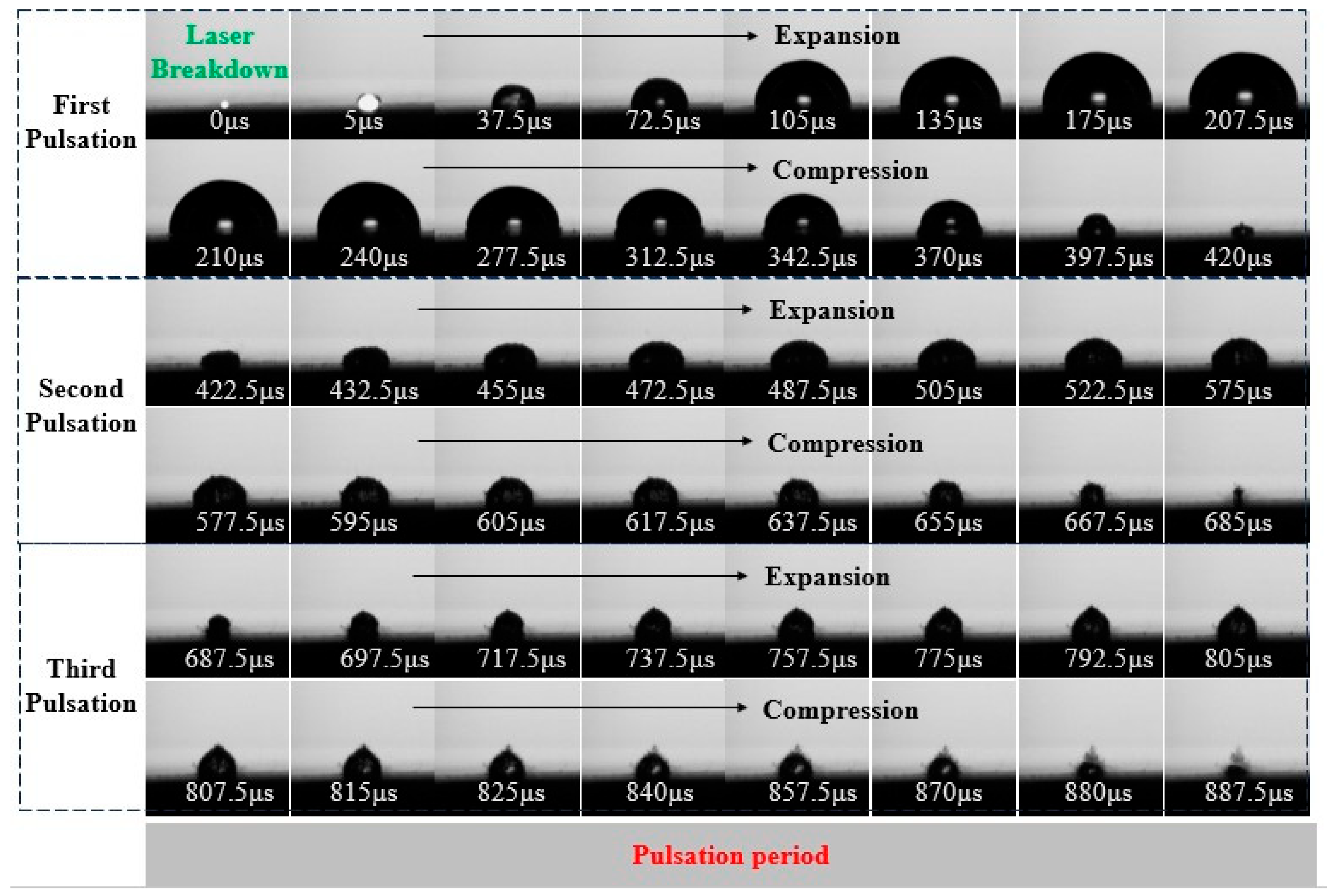
The evolution of a cavitation bubble induced by laser with an energy of 400 mJ is shown in Figure 4. The cavitation bubble induced by the laser exhibits three evolution periods, and the total duration of these three evolution periods is 887.5 μs. At 0 μs, the laser breaks down the local liquid, and high-temperature and high-pressure plasma [4] is formed on the surface of the material. Promoted by the solid–liquid pressure, the cavitation bubble begins to expand near the wall. However, the existence of the solid wall causes the cavitation bubble to expand in a hemispherical shape, and then the cavitation bubble enters the evolution process. The first evolution period is from 5 μs to 420 μs, with a total duration of 415 μs. The second evolution period is from 422.5 μs to 685 μs, during which an irregular hemispherical cavitation bubble is formed. The third evolution period is from 687.5 μs to 887.5 μs. The durations of the second and third evolution periods are shortened to 262.5 μs and 200 μs, respectively. After the cavitation bubble experiences these three evolution periods, it eventually collapses and dissipates in the liquid. The relationship between the size of the cavitation bubble and time induced by a laser energy of 400 mJ is shown in Figure 5. It can be seen from Figure 5 that the maximum radius of the cavitation bubble decreases with the increase in the number of evolution periods. The maximum radius of the cavitation bubble in the first evolution period is 2.8 mm, and the maximum radii of the cavitation in the second and third evolution periods are 1.61 mm and 1.26 mm, respectively. The decline rates gradually slow down to 42.5% and 21.74%, respectively. It can be inferred that the energy of the cavitation bubble decreases with the number of evolution periods, and most of the energy of the cavitation bubble is consumed during the first evolution process.
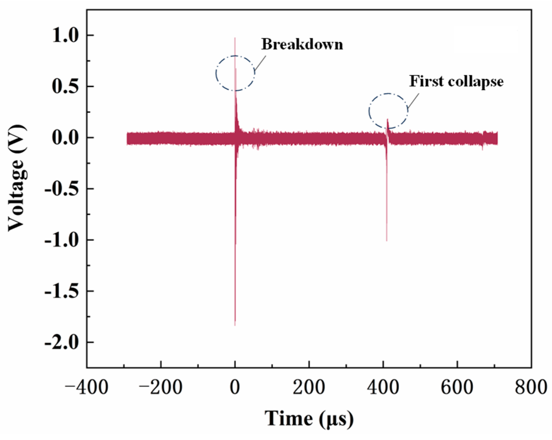
The laser-induced cavitation bubble underwater acoustic signal with an energy of 400 mJ is shown in Figure 6. It can be seen from Figure 6 that the optical fiber hydrophone captures two underwater acoustic signals in total. According to previous studies [15], the first wave peak represents the laser plasma shock wave. At 0 μs, the laser breaks down the local liquid, and plasma is formed on the specimen surface, resulting in a plasma shock wave. The mechanical effect of the plasma shock wave acts on the surface of the material and is captured by the optical fiber hydrophone probe to form the first wave peak. The second wave peak is located at 420 μs, representing the shock wave generated by the cavitation bubble collapse in the first evolution period. The failure to capture the second period’s collapse shock wave signal indicates that the cavitation bubble energy in the second evolution period is small and it is difficult to form a capturable shock wave. Given the decreasing trend of energy combined with the increase in the number of evolution periods shown in Figure 5, it can be inferred that the third evolution period’s collapse shock wave signal cannot be captured, further proving that most of the energy of the cavitation bubble is consumed in the first evolution process. In addition, some small wave peaks are still observed, but they are inconsistent with the evolution cycle of the cavitation bubble, which proves that they are not caused by cavitation bubble collapse. According to the research of scholars Lu et al. [28], it can be inferred that the tiny wave peaks in the underwater acoustic signal may be caused by the weak shock wave generated by the cavitation bubble during the evolution process and the noise signal generated during the operation of the laser, and they are unavoidable and negligible interference signals.
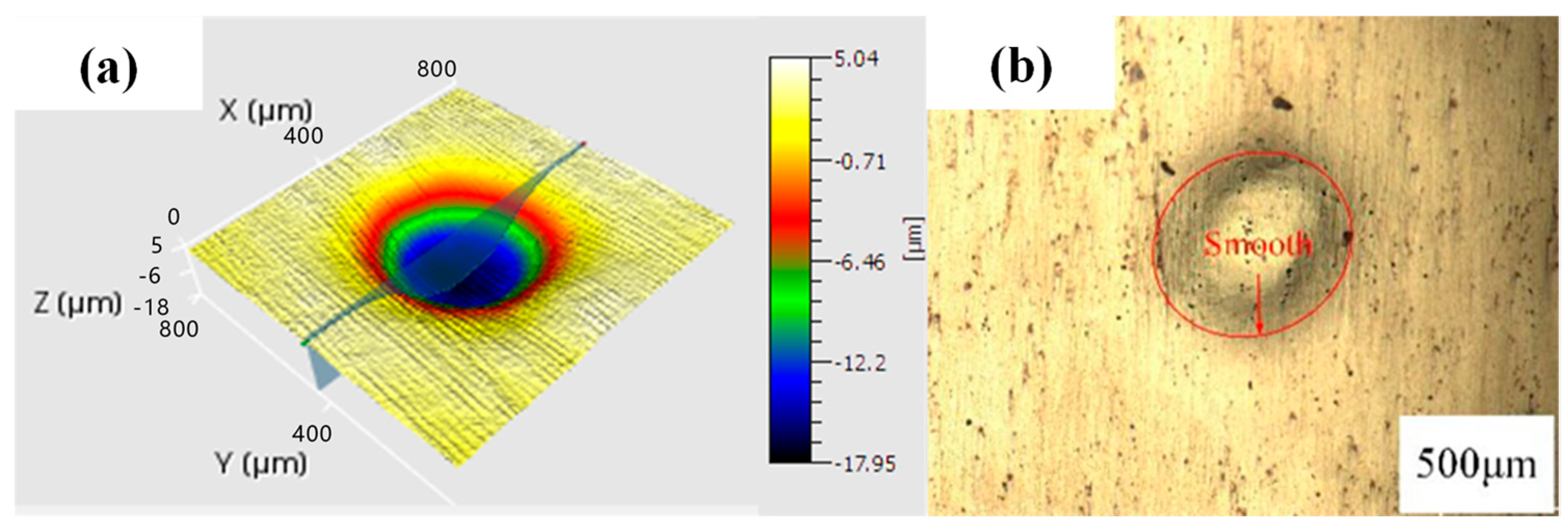
After laser-induced cavitation bubble impact, a micropit was formed on the surface of the sample. The morphology of the micropit was observed by confocal microscopy, as shown in Figure 7. The surface of the micropit formed by laser-induced cavitation bubble has no ablation generated, which can be seen in the combination of Figure 5 and Figure 6. The micropit is formed under the combined action of the plasma shock wave and the first period collapse shock wave, and the impact of shock waves generated by other evolution periods is small, which proves the feasibility of laser-induced cavitation bubble formation for micropit.

3.2. Study on Surface Morphology of Microtexture Formed by Laser-Induced Cavitation Bubble

Micropits were formed at different positions on the sample surface successively to form microtexture. In order to better reflect the influence of density on microtexture morphology, the density of the laser-induced cavitation bubble was optimized by means of an arithmetic sequence method, and samples with different densities of microtexture were manufactured. The parameters of the samples are shown in Table 4, following the calculation formula of density [29], where ρt is the density of the microtexture, r is the diameter of micropits, and L is the center distance of micropits. In this experiment, the values of L selected were 1.5 mm, 1.25 mm, 1 mm, and 0.75 mm.
ρ t = π r 2 / L 2 × 100 %
After the laser-induced cavitation bubble impact, macroscopic observation of the microtexture arrays was conducted. Samples with different microtexture densities are shown in Figure 8. Microtextures with densities of 8.72%, 12.56%, 19.63%, and 34.88% were formed on the surface of 7050 aluminum alloy using laser-induced cavitation bubbles. The overall morphology of these microtexture is of regular circular micropits.
The three-dimensional morphology of the sample surface observed by a confocal microscopy is shown in Figure 9. It can be seen from Figure 9 that microtexture edges of different densities have small protrusions. When the density of microtexture is 34.88%, the protrusions may affect the edge morphology of surrounding micropits, resulting in defects. When the densities of microtexture are 8.72%, 12.56%, and 19.63%, the microtexture surface morphology is flat, and the protrusions do not affect the adjacent micropits. No cracks are found at the micropits boundary, which proves that laser-induced cavitation can form microtexture with good surface morphology.
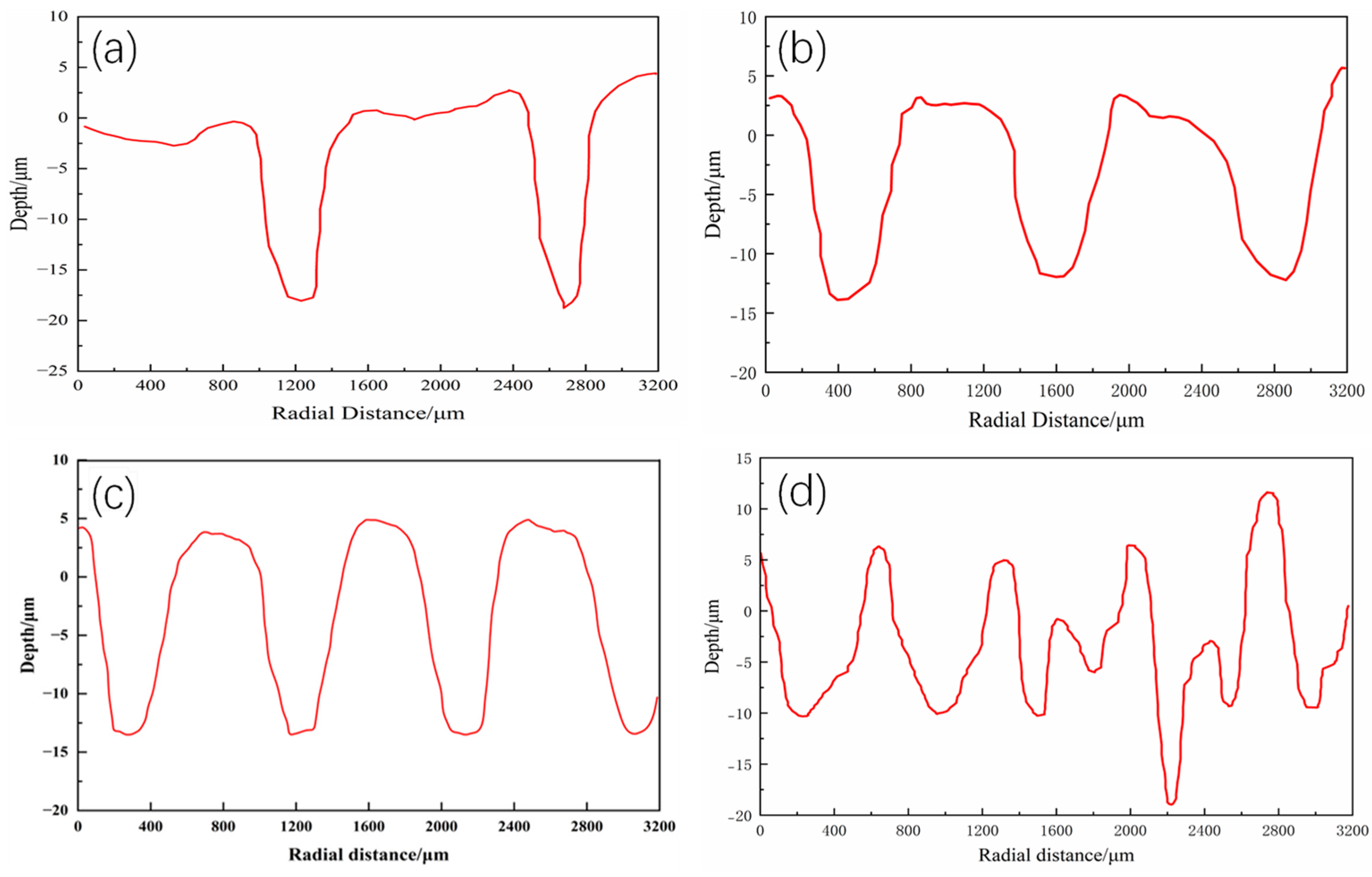
The two-dimensional cross-sections of samples with varying microtexture densities are shown in Figure 10. As evident from Figure 10, there is no significant change in the size of micropits within the same density level. For the sample with a density of 8.72%, the diameter of the micropits is approximately 478 μm, and the average depth is 18.25 μm. As the density of microtexture increases, the diameter of the micropits generally exhibits an increasing trend, whereas the depth shows a decreasing trend. At densities of 19.63% and 12.56%, the size of the micropits changes minimally, with a diameter of approximately 578 μm and an average depth of approximately 13.56 μm. As shown in Figure 11, the hardness at the bottom of the micropits increases with density. This could be attributed to the introduction of compressive stress during the formation of adjacent micropits, leading to local strengthening of the sample and inhibiting the downward growth of the micropits, directing micropits’ expansion towards the surrounding areas instead. However, when the density increases from 12.56% to 19.63%, the diameters of the micropits decrease. Combining this with Figure 11, it is apparent that at a density of 19.63%, the hardness of the spacing area between micropits increases significantly. This may stem from the decreased distance between micropits and the increased extrusion forces between them. According to Figure 10d, when the density is excessively high, the presence of adjacent micropits significantly impacts the topography of the micropits. The depth of the micropits becomes less than 10 μm, and even stratification and distortion are observed.
In summary, microtexture formed by laser-induced cavitation bubble has a certain impact on the mechanical properties of the sample, but it does not cause deterioration of mechanical properties. When the density of the microtexture is less than or equal to 19.63%, the size of the microtexture is primarily influenced by laser parameters. Specifically, the diameters of the micropits range from 478 μm to 578 μm, and the depths of the micropits range from 13.56 μm to 18.25 μm. This demonstrates that laser-induced cavitation bubble technology can be utilized to create repeatable microtexture with a specific density and depth, and favorable surface topography.

3.3. Study on Friction and Wear Properties of Microtexture Formed by Laser-Induced Vacuuming

Microtexture on material surface is widely used to enhance the properties of metal materials, and the friction coefficient is a crucial index for evaluating the quality of the microtexture. To further investigate the optimal process density of microtexture formed by laser-induced cavitation bubble technology, friction and wear tests were conducted on samples with varying densities to determine the optimal density.
The variation of the friction coefficient is shown in Figure 12a. The evolution of the internal friction coefficient during the first 50 s of the running-in period is shown in Figure 12b. It is evident from Figure 12b that the friction coefficients of the five groups of samples are initially very high and exhibit a pronounced decline within the first 5 s. This can be attributed to the presence of small protrusions and indentations on the sample surface, leading to a reduced actual contact area and a significant increase in the friction coefficient. As time progresses and the grinding effect of the friction pairs takes place, the protrusions gradually diminish, the sample surface becomes smoother, and the wear rate gradually decelerates. The test reaches a stable wear stage within 50 s, characterized by a significantly reduced wear rate and a relatively stable friction coefficient, which persists until the sample fails or the test concludes.
Figure 12a reveals that after stabilization, the friction coefficient of the sample with a microtexture density of 0% continues to rise slowly, with the friction curve sharply increasing and exhibiting violent oscillations in the later stages of friction. This is higher than in the samples with microtexture. The absence of micropits on the untextured sample’s surface prevents the storage of oil for lubrication, resulting in the continuous consumption and gradual destruction of the lubricating film formed during the initial friction stages under starved lubrication conditions. Consequently, the friction pair’s contact form transitions from mixed friction to dry friction, leading to a higher friction coefficient. In contrast, the friction coefficients of the microtextured samples decrease rapidly. Samples with varying microtexture densities also exhibit distinct trends in the running-in and steady-state stages. Notably, the friction coefficient of the sample with a microtexture density of 8.72% increases slowly after the stable wear stage, followed by a sharp increase and violent oscillations at 350 s into the friction test. This stage stabilizes again after 100 s. This behavior is attributed to the reduced number of micropits, which fails to adequately store abrasive particles and oil generated during friction. These impurities accumulate in the pit spacing, altering the lubrication and friction conditions, causing the friction to re-enter the running-in period. Therefore, the friction curve of the sample with a microtexture density of 8.72% exhibits a similar trend to that of the untextured sample. The friction coefficient trends of the other three groups of samples are uniform, with the friction stability stage lasting until the end of the test. However, the curve of the sample with a microtexture density of 34.88% is higher than that of the sample with a microtexture density of 19.63%. This is determined to be due to the increased microtexture density decreasing the area of the sample’s contact surface, resulting in severe uneven wear of the wear track [30,31]. Additionally, as shown in Figure 9d, defects in the microtexture surface contribute to the higher friction coefficient of the sample with a microtexture density exceeding 19.63%.
As shown in Figure 12, the microtexture formed by laser-induced cavitation bubble exhibits a pronounced lubrication effect, resulting in a friction coefficient lower than that of the untreated sample. Notably, the sample with a microtexture density of 19.63% exhibits the minimum friction coefficient, averaging at 0.14. In conclusion, the optimal process parameter density for forming microtexture by laser-induced cavitation bubble is 19.63%.

4. Conclusions

In this paper, the formation of microtexture with different densities by laser-induced cavitation bubble is examined, which provides a basis for further study of the microtexture technology of laser-induced cavitation bubbles.
The micropit is formed under the combined action of the plasma shock wave and the cavitation bubble collapse shock wave during the first evolution period, and its surface is formed without ablation. This indicates that the laser-induced cavitation bubble is capable of forming microtexture on the surface of the sample.
When the density of microtexture is less than or equal to 19.63%, the sample has a smooth surface without ablation, and the microtexture size is primarily influenced by laser parameters. The diameters of the micropits range from 478 μm to 578 μm, and the depths of the micropits range from 13.56 μm to 18.25 μm. This demonstrates that laser-induced cavitation bubbles can produce repeatable microtexture with specific density and depth on the surface of 7050 aluminum alloy.
The average friction coefficients of the samples with densities of 8.72%, 12.56%, 19.63%, and 34.88% are 0.153, 0.146, 0.140, and 0.142, respectively. These values are lower than that of the untextured sample, which has an average friction coefficient of 0.16. This proves that the microtexture formed by laser-induced cavitation bubble has a significant lubrication effect. Furthermore, the friction coefficient shows a decreasing trend with increasing density. When the density of microtexture is 19.63%, the surface morphology is flat with no obvious defects, having the minimum friction coefficient. Therefore, the optimal density of microtexture is 19.63%.

Author Contributions

Conceptualization, B.L. and B.-W.M.; data curation, B.L. and H.G.; formal analysis, B.L., B.-W.M. and Y.M.; funding acquisition, Y.C.; investigation, R.Z.; methodology, B.L. and B.-W.M.; project administration, Y.C.; resources, R.Z., H.G. and Y.C.; software, B.L. and B.-W.M.; supervision, H.G. and Y.C.; validation, B.L. and Y.M.; writing—original draft, B.L.; writing—review and editing, Y.M. and R.Z. All authors have read and agreed to the published version of the manuscript.

Funding

The Doctoral Studio Research Project of Nantong Institute of Technology (Grant No. ZX202102), the Science and Technology Project of Nantong (Grant Nos. JC2023059, JCZ2023001), the Natural Science Foundation of the Jiangsu Higher Education Institutions of China (Grant Nos. 21KJB460018, 24KJA460007), the Jiangsu Province Higher Education Excellent Science and Technology Innovation Team Laser Processing and Metal Additive Manufacturing Technology and Application (Grant No. SJK2023-3), the Priority Discipline Construction Program of Jiangsu Province (Grant No. 2022-2), and the Key Laboratory of Laser Processing and Metal Additive of the provincial science and technology service platform cultivation project of Nantong Institute of Technology (Grant No. XQPT202101).

Institutional Review Board Statement

Not applicable.

Informed Consent Statement

Not applicable.

Data Availability Statement

The original contributions presented in the study are included in the article; further inquiries can be directed to the corresponding authors.

Conflicts of Interest

The authors have no conflicts to disclose.

References

  1. Zhang, Z.; Wei, S.; Wang, P.; Qiu, W.; Zhang, G. Progress in applications of laser induced cavitation on surface processing. Opt. Laser Technol. 2024, 170, 110212. [Google Scholar] [CrossRef]
  2. Wee, L.M.; Ng, E.Y.K.; Prathama, A.H.; Zheng, H. Micro-machining of silicon wafer in air and under water. Opt. Laser Technol. 2011, 43, 62–71. [Google Scholar] [CrossRef]
  3. Bao, J.; Long, Y.; Tong, Y.; Yang, X.; Zhang, B.; Zhou, Z. Experiment and simulation study of laser dicing silicon with water-jet. Appl. Surf. Sci. 2016, 387, 491–496. [Google Scholar] [CrossRef]
  4. Zhou, R.; Li, K.; Cao, Y.; Shi, W.; Yang, Y.; Tan, L.; Hu, R.; Jin, Y. Experimental Study of Laser induced Cavitation Bubble near Wall: Plasma Shielding Observation. Water 2024, 16, 1324. [Google Scholar] [CrossRef]
  5. Nath, A.; Keare, A. Measurement of charged particles and cavitation bubble expansion velocities in laser induced breakdown in water. Laser Part. Beams 2008, 26, 425–432. [Google Scholar] [CrossRef]
  6. Klaseboer, E.; Fong, S.W.; Turangan, C.K.; Khoo, B.C.; Szeri, A.J.; Calvisi, M.L. Interaction of lithotripter shockwaves with single inertial cavitation bubble. J. Fluid Mech. 2007, 593, 33–56. [Google Scholar] [CrossRef]
  7. Lai, G.; Geng, S.; Zheng, H.; Yao, Z.; Zhong, Q.; Wang, F. Early Dynamics of a Laser induced Underwater Shock Wave. J. Fluids Eng.-Trans. ASME 2022, 144, 011501. [Google Scholar] [CrossRef]
  8. Wen, H.; Yao, Z.; Zhong, Q.; Tian, Y.; Sun, Y.; Wang, F. Energy partitioning in laser induced millimeter-sized spherical cavitation up to the fourth oscillation. Ultrason. Sonochem. 2023, 95, 106391. [Google Scholar] [CrossRef]
  9. Brujan, E.-A.; Vogel, A. Stress wave emission and cavitation bubble dynamics by nanosecond optical breakdown in a tissue phantom. J. Fluid Mech. 2006, 558, 281, Erratum in J. Fluid Mech. 2008, 608, 411. [Google Scholar] [CrossRef]
  10. Sankin, G.N.; Yuan, F.; Zhong, P. Pulsating Tandem Microbubble for Localized and Directional Single-Cell Membrane Poration. Phys. Rev. Lett. 2010, 105, 078101. [Google Scholar] [CrossRef]
  11. Sinibaldi, G.; Occhicone, A.; Pereira, F.A.; Caprini, D.; Marino, L.; Michelotti, F.; Casciola, C.M. Laser induced cavitation: Plasma generation and breakdown shockwave. Phys. Fluids 2019, 31, 103302. [Google Scholar] [CrossRef]
  12. Chichkov, B.N.; Momma, C.; Nolte, S.; Von Alvensleben, F.; Tünnermann, A. Femtosecond, picosecond and nanosecond laser ablation of solid. Appl. Phys. A 1996, 63, 109–115. [Google Scholar] [CrossRef]
  13. Mao, B.; Li, B.; Lin, D.; Liao, Y. Enhanced room temperature-stretch formability of AZ31B magnesium alloy sheet by laser shock peening. Mater. Sci. Eng. A 2019, 756, 219–225. [Google Scholar] [CrossRef]
  14. Wang, L.; Guo, Z.; Deng, Y.; Chen, T.; Xie, M.; Xiao, Y.; Zou, Z. Experimental research into microgroove stamping by laser induced cavitation. Opt. Laser Technol. 2022, 146, 107549. [Google Scholar] [CrossRef]
  15. Cao, Y.; Hu, R.; Shi, W.; Zhou, R. Experimental Study on Near-Wall Laser induced Cavitation Bubble Micro-Dimple Formation on 7050 Aluminum Alloy. Water 2024, 16, 1410. [Google Scholar] [CrossRef]
  16. Ren, X.D.; He, H.; Tong, Y.Q.; Ren, Y.P.; Yuan, S.Q.; Liu, R.; Wang, D.S. Experimental investigation on dynamic characteristics and strengthening mechanism of laser induced cavitation bubble. Ultrason. Sonochem. 2016, 32, 218–223. [Google Scholar] [CrossRef]
  17. Tzanakis, I.; Eskin, D.G.; Georgoulas, A.; Fytanidis, D.K. Incubation pit analysis and calculation of the hydrodynamic impact pressure from the implosion of an acoustic cavitation bubble. Ultrason. Sonochem. 2014, 21, 866–878. [Google Scholar] [CrossRef]
  18. Long, J.; Eliceiri, M.H.; Ouyang, Y.; Zhang, Y.; Xie, X.; Grigoropoulos, C.P. Effects of immersion depth on the dynamics of cavitation bubble generated during ns laser ablation of submerged targets. Opt. Lasers Eng. 2021, 137, 106334. [Google Scholar] [CrossRef]
  19. Long, J.; Eliceiri, M.H.; Wang, L.; Vangelatos, Z.; Ouyang, Y.; Xie, X.; Zhang, Y.; Grigoropoulos, C.P. Capturing the final stage of the collapse of cavitation bubble generated during nanosecond laser ablation of submerged targets. Opt. Laser Technol. 2021, 134, 106647. [Google Scholar] [CrossRef]
  20. Soyama, H.; Kikuchi, T.; Nishikawa, M.; Takakuwa, O. Introduction of compressive residual stress into stainless steel by employing a cavitating jet in air. Surf. Coat. Technol. 2011, 205, 3167–3174. [Google Scholar] [CrossRef]
  21. Zhang, H.; Ren, X.; Tong, Y.; Larson, E.A.; Adu-Gyamfi, S.; Wang, J.; Li, X. Surface integrity of 2A70 aluminum alloy processed by laser induced peening and cavitation bubble. Results Phys. 2019, 12, 1204–1211. [Google Scholar] [CrossRef]
  22. Gu, J.; Liu, H.; Luo, Z.; Liu, A.; Ren, X. Laser cavitation processing of mild steel: Surface integrity, microstructure and stress corrosion performance. Mater. Today Commun. 2023, 35, 105464. [Google Scholar] [CrossRef]
  23. Takada, N.; Nakano, T.; Sasaki, K. Formation of cavitation-induced pits on target surface in liquid-phase laser ablation. Appl. Phys. A-Mater. Sci. Process. 2010, 101, 255–258. [Google Scholar] [CrossRef]
  24. Wang, L.; Deng, Y.; Zou, Z.; Xiao, Y.; Su, G.; Guo, Z. The forming of microgroove in copper foil on multiple laser induced cavitation impacts. J. Manuf. Process. 2022, 78, 82–91. [Google Scholar] [CrossRef]
  25. Wang, L.; Deng, Y.; Zou, Z.; Xiao, Y.; Su, G.; Guo, Z. Microgroove formation in thin copper by laser induced cavitation bubble shock: Numerical and experimental investigation. Appl. Opt. 2022, 61, 1841–1850. [Google Scholar] [CrossRef] [PubMed]
  26. Zhang, Z.; Zhang, Y.; Liu, D.; Zhang, Y.; Zhao, J.; Zhang, G. Bubble Behavior and Its Effect on Surface Integrity in Laser induced Plasma Micro-Machining Silicon Wafer. J. Manuf. Sci. Eng.-Trans. ASME 2022, 144, 091008. [Google Scholar] [CrossRef]
  27. Ye, Y.; Wu, M.; Ren, X.; Zhou, J.; Li, L. Hole-like surface morphologies on the stainless steel surface through laser surface texturing underwater. Appl. Surf. Sci. 2018, 462, 847–855. [Google Scholar] [CrossRef]
  28. Lu, Z.; Gu, J.; Zhang, P.; Luo, C.; Ren, X. Investigation on laser cavitation micro-forming process: Deformation behavior of 1060 aluminum foil and bubble evolution in a gap. J. Manuf. Process. 2021, 67, 619–627. [Google Scholar] [CrossRef]
  29. Cao, Y.; Hu, R.; Shi, W.; Wang, Z.; Qiu, M.; Zhang, X.; Li, B. Experimental study on laser peen texturing and tribological properties of E690 high-strength steel. Opt. Laser Technol. 2023, 157, 108784. [Google Scholar] [CrossRef]
  30. Zhang, J.; Wu, C.; Shi, X.; Xue, Y.; Huang, Q.; Zhang, K. Tribological Properties and Frictional Noise Behavior of Inconel 625 with Microtexture Filled by Sn-Ag-Cu. J. Mater. Eng. Perform. 2022, 31, 82–93. [Google Scholar] [CrossRef]
  31. Yang, X.; Fu, Y.; Ji, J.; Chen, T.; Pan, C. Study on tribological properties of surface concave convex microtexture on the mold steel. Ind. Lubr. Tribol. 2020, 72, 1167–1171. [Google Scholar] [CrossRef]
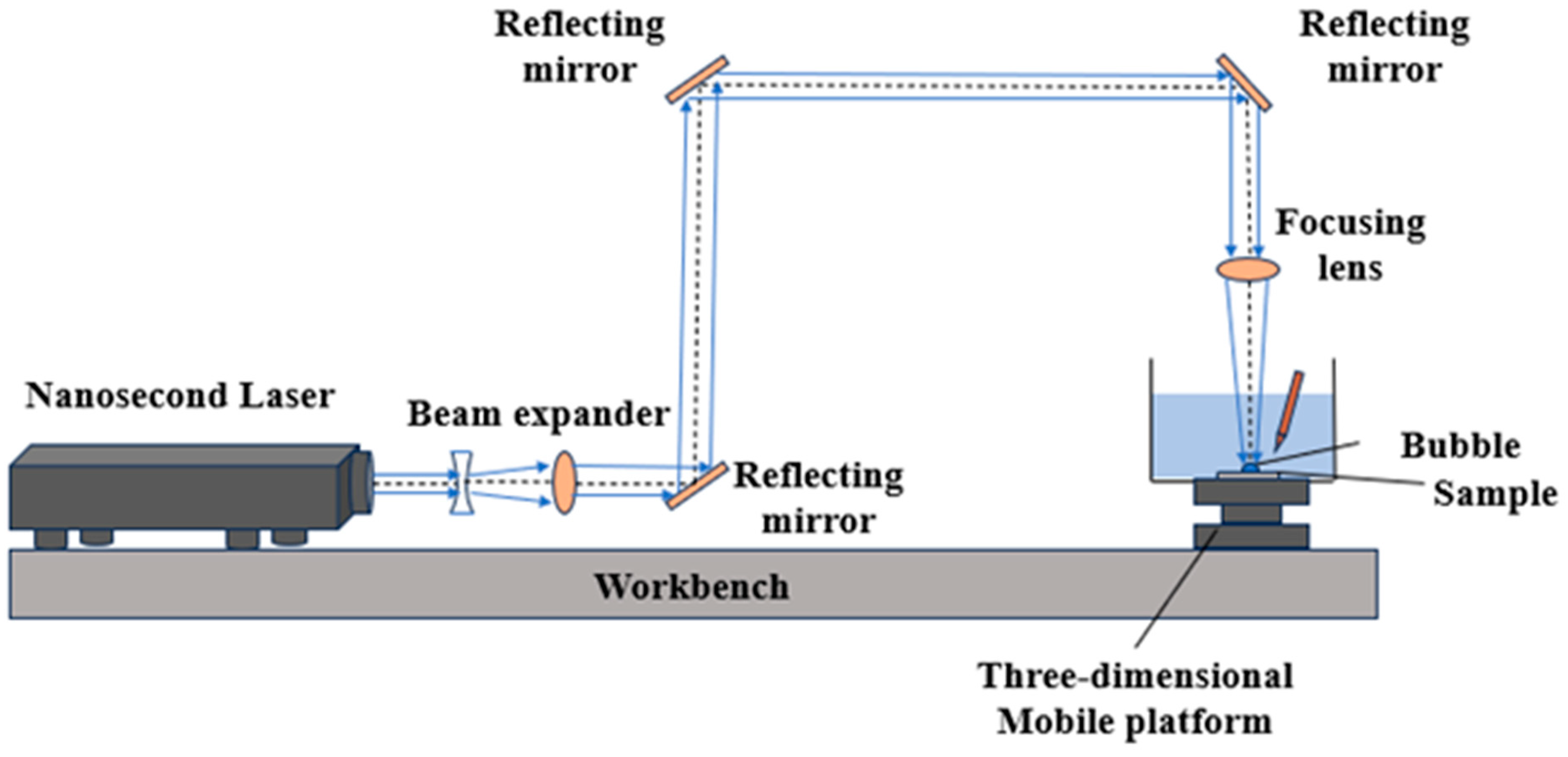
Figure 1. Schematic diagram of laser-induced cavitation bubble microtexture platform.
Coatings 14 01230 g001
Figure 2. Test equipment: (a) high-speed camera, (b) fiber optic hydrophone, (c) confocal microscope, (d) friction and wear testing machine.
Coatings 14 01230 g002
Figure 3. The route of microtexture formed by laser-induced cavitation bubble.
Coatings 14 01230 g003
Figure 4. Evolution of laser-induced cavitation bubble with an energy of 400 mJ.
Coatings 14 01230 g004
Figure 5. Relationship between size and time of laser-induced cavitation bubble with an energy of 400 mJ.
Coatings 14 01230 g005
Figure 6. Underwater acoustic signal of laser-induced cavitation bubble with energy of 400 mJ.
Coatings 14 01230 g006
Figure 7. The micropitted three-dimensional morphology of the specimen surface: (a) three-dimensional morphology of the micropit, (b) the morphology of the micropit.
Coatings 14 01230 g007
Figure 8. Macroscopic morphology of samples with different densities: (a) 0%, (b) 8.72%, (c) 12.56%, (d) 19.63%, (e) 34.88%.
Coatings 14 01230 g008
Figure 9. Surface 3D morphology of samples with different densities: (a) 8.72%, (b) 12.56%, (c) 19.63%, (d) 34.88%.
Coatings 14 01230 g009
Figure 10. Two-dimensional cross-section of samples with different densities: (a) 8.72%, (b) 12.56%, (c) 19.63%, (d) 34.88%.
Coatings 14 01230 g010
Figure 11. Relationship between mechanical properties of sample and density.
Coatings 14 01230 g011
Figure 12. Friction curves of different microtexture densities. (a) 600S rule of friction coefficient. (b) 50S rule of friction coefficient.
Coatings 14 01230 g012
Table 1. 7050 aluminum alloy physical and mechanical properties [15].
DensityModulus of ElasticityPoisson’s RatioYield StrengthTensile Strength
2780/(kg·m−3)72 GPa0.33435.7 MPa534.624 MPa
Table 2. Parameters of friction test.
Test Parameter ValueNumerical Value
Frequency (Hz)2
Load (N)8
Time (s)600
Room temperature (°C)8
Travel (mm)25
Table 3. Parameters of laser-induced cavitation bubble microtexture test [15].
Test Parameter ValueNumerical Value
Wave length (nm)1064
Pulse width (ns)9
Frequency (Hz)5
Spot diameter (mm)0.5
Energy (mJ)400
Number of shocks1
Table 4. Process parameters of laser-induced cavitation bubble microtexture.
Test NumberDensity of Microtexture
10%
28.72%
312.56%
419.63%
534.88%
Disclaimer/Publisher’s Note: The statements, opinions and data contained in all publications are solely those of the individual author(s) and contributor(s) and not of MDPI and/or the editor(s). MDPI and/or the editor(s) disclaim responsibility for any injury to people or property resulting from any ideas, methods, instructions or products referred to in the content.