Abstract
This study investigates the fabrication of a ZrSiO4-based coating (ZSO coating) on substrate surfaces using atmospheric plasma spraying (APS) technology, with ZrSiO4 as the feedstock material. A comprehensive characterization of the coating systems was conducted, including an in-depth analysis of phase composition and a systematic evaluation of the effects of spray thickness and heat treatment temperature on phase evolution, microstructural development, and the resulting properties. The coatings’ resistance to silicon corrosion and the associated failure mechanisms were thoroughly examined. The key findings reveal that the plasma-sprayed coatings form a multiphase system composed of ZrSiO4, along with the decomposition products of ZrO2 and SiO2. Optimal performance was observed within a critical thickness range of 154–240 μm. Post-deposition heat treatment at 1500 °C significantly improved the integrity of the coatings, as evidenced by a marked reduction in crack density and porosity, leading to substantial enhancement in densification. The coatings demonstrated outstanding performance in the high-temperature silicon corrosion tests, maintaining structural integrity after 4 h of exposure to molten silicon and its oxides at 1500 °C. Notably, the coatings effectively prevented the penetration of silicon into the C/C substrate, preserving strong interfacial adhesion without the formation of permeable cracks. Furthermore, post-corrosion analysis showed that the surface reaction products could be easily removed, underscoring the coatings’ exceptional protective capability for the underlying C/C substrate.
1. Introduction
The new energy industry plays a crucial role in national renewable energy development strategies, with silicon-based cells dominating the market. Monocrystalline and polycrystalline Si provide the foundational materials for photovoltaic conversion. In the production of crystalline Si, carbon/carbon (C/C) composites, known for their elevated strength, low thermal expansion coefficient, impact resistance, high modulus, and excellent corrosion resistance, have emerged as ideal structural materials for the thermal environments within Si furnaces. During the manufacturing process of crystalline Si, elevated temperatures lead to the volatilization of substantial amounts of SiO2 and Si vapor from the quartz crucibles containing the Si feedstock and molten Si. When these gases interact with carbon-based thermal field materials, silicide reactions may occur, resulting in material corrosion that significantly compromises the structural integrity of the materials which destabilizes the thermal field. Furthermore, this poses safety risks to the crystalline Si furnace equipment.
Given the limited research on the silicon corrosion resistance of C/C composites, this study aims to address this gap by conducting a comprehensive investigation into several mainstream technologies, focusing on both substrate modification [1,2] and surface coating techniques [3,4]. Notably, dense coatings have demonstrated significant efficacy in isolating the substrate from the silicon-containing medium, playing a decisive role in enhancing the silicon corrosion resistance of C/C composites in high-temperature environments. Consequently, the development of coatings with exceptional silicon corrosion resistance to ensure the safe operation of C/C composites has become a central focus in the current research landscape [5]. Extensive research has established that ZrSiO4 is more readily available than ZrO2, occurring naturally in sandy deposits across much of the Earth’s surface, which significantly reduces material costs. This silicate ceramic exhibits outstanding thermal properties, including a thermal conductivity of 5.1 W/m·°C at room temperature that decreases to 3.5 W/m·°C below 1000 °C [6]. Notably, it maintains a remarkably low linear thermal expansion coefficient of 4.1 × 10⁻⁶ °C−1 across a broad temperature range from ambient to 1400 °C [7]. The material also demonstrates exceptional chemical corrosion resistance and a high dissociation temperature of 1675 °C [8,9], which exceeds the typical silicon production temperature of 1500 °C, suggesting its strong potential as a silicon-corrosion-resistant coating.
Given these superior properties and excellent compatibility with C/C composites, ZSO coatings are particularly promising for high-temperature silicon corrosion protection in C/C composite systems. APS [10,11,12] offers distinct advantages for this application, including cost-effectiveness, established industrial infrastructure, compatibility with diverse feedstock materials, and high deposition rates, making it one of the most competitive coating technologies [13]. The high melting point of ZrSiO4 is effectively addressed by APS, as the process enables rapid melting and deposition of zirconium silicate particles that form strong mechanical interlocking with the C/C substrate surface.
In this study, the APS technique was used to synthesize ZSO coating on the surface of C/C composites. The optimal coating thickness was established by systematically varying the number of spraying passes. Uncoated C/C substrates were also prepared as a control for comparative analysis. The resistance of the coatings to Si element corrosion was subsequently assessed in an argon atmosphere at a temperature of 1500 °C with Si, SiO and SiO2 as the corrosion medium. This study comprehensively examined the phase composition, microstructural characteristics, and elemental distribution of the coatings before and after the corrosion exposure and the protective mechanism was discussed in detail.
2. Experimental Section
2.1. Coating Preparation
In this study, needled C/C composite with a density of 1.5 g/cm3 and commercially available ZrSiO4 powders (particle size 1.5–5 µm) (Baishun Biotechnology Co., Ltd., Shanghai, China) are used as raw materials. The comprehensive procedure for the preparation of ZSO coatings on the C/C samples is outlined as follows and illustrated in Figure 1:
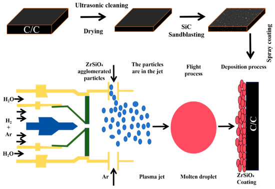
Figure 1.
Flow chart of atmospheric plasma sprayed ZSO coating.
- The C/C samples were cleaned ultrasonically for 6 min using an ultrasonic cleaning system (DY-040S-2, Ding Yu, Shenzhen, China) and then dried in an oven for 9 h.
- The cleaned C/C composite samples underwent sandblasting with a sandblasting machine (BH-PS1090DA-Z, Bai Hui, Wenzhou, China), using SiC particles (50 mesh size) as the abrasive material, for 3 s.
- The CZrSiO4-agglomerated powder with a particle size of 400 mesh was employed as the raw material for APS. The spraying process parameters were configured to include 1–4 deposition cycles, with each cycle lasting 2 s, resulting in the successful preparation of a ZSO coating on the surface of C/C composites. During the spraying process, a mixture of Ar and H2 was utilized as the working gas. Ar, a commonly used plasma gas, exhibits high ionization energy and stability. Under the influence of a high-voltage electric field, argon ionizes to form a plasma, providing a high-temperature and high-energy environment. H2, on the other hand, serves as a potent reducing agent, capable of establishing a reducing atmosphere at elevated temperatures. This atmosphere aids in removing oxides from the material surface, particularly preventing oxidation of the coating during the spraying process. The spraying parameters are listed in Table 1.
 Table 1. The spraying parameters for ZSO coating.
2.2. Corrosion Process
The ZSO-coated samples were cut into approximately 10 × 10 × 10 mm cubes and placed in BN crucibles (to prevent the failure of ordinary graphite crucibles at high temperatures, BN crucibles with excellent heat resistance were selected as an alternative material). The samples were then embedded with Si, SiO, and SiO2 powders, respectively. The corrosion tests were conducted in a tube furnace (TL-1500, BYT, Tianjin, China) at 1500 °C in an Ar atmosphere for 4 h, followed by cooling in the furnace. Meanwhile, uncoated C/C substrates served as control samples under identical corrosion conditions.
2.3. Microstructure and Phase Characterizations
The phase composition of the samples was characterized by X-ray diffraction (XRD, BRUKER D8 ADVANCE-A2, Saarbrücken, Germany) using Cu Kα radiation (λ = 1.5406 Å). The measurements were conducted under the following conditions: an accelerating voltage of 40 kV, a tube current of 40 mA, and a scanning step size of 0.02° in continuous scan mode. To enhance data quality, a monochromatic filter was employed to eliminate Kβ radiation and minimize fluorescence background. No peak fitting was applied during data acquisition to ensure the integrity of the raw diffraction patterns [14]. Microstructural features, including both surface and cross-sectional coatings, were examined with field emission scanning electron microscopy (FESEM, TESCAN MIRA LMS, Brno, Czech Republic). Elemental composition analysis was conducted using an energy-dispersive X-ray spectrometer (EDS, Quantax 200 XFlash 6|60, BRUKER, Saarbrücken, Germany) coupled with field-emission scanning electron microscopy (FESEM). The EDS measurements were performed at an accelerating voltage of 20 kV, utilizing secondary electron imaging mode for optimal spatial resolution and elemental detection.
3. Results and Discussion
3.1. Microstructure and Composition
The macroscopic structure of the ZSO-coated specimens, depicted in Figure 2, exhibits several notable features. The ZSO coating appears white with a rough surface characterized by protrusions and recesses, a result of the sandblasting treatment applied before APS. This treatment improves the adhesion of the ZSO coating to the C/C. Furthermore, the ZSO coating demonstrates excellent spreadability on the C/C, resulting in a homogeneous distribution without evidence of agglomeration [15].

Figure 2.
Typical macroscopic structure of ZSO-coated specimens.
Figure 3a presents the XRD patterns of both the ZrSiO4 powder and the surface of the ZSO coating. Compared to the ZrSiO4 powder, the intensity of the ZrSiO4 diffraction peaks in the ZSO coating is significantly reduced, while diffraction peaks corresponding to three phases—m-ZrO2, t-ZrO2, and SiO2—are observed, indicating the partial decomposition of ZrSiO4 into ZrO2 and SiO2. The researchers found that the high temperatures in the plasma jet decomposed ZrSiO4 [16,17], and the rapid quenching on the C/C substrate prevented its reformation from SiO2 and ZrO2. According to the widely accepted binary phase diagram established by Butterman and Foster [18,19], m-ZrO2 is the stable phase at low temperatures, while t-ZrO2 exhibits stability at high temperatures. After spraying, as the temperature decreases, t-ZrO2 is expected to transform into m-ZrO2. However, on one hand, the presence of SiO2 inhibits this phase transformation [20,21], and alternatively, after spraying, the surface temperature of the ZSO coating rapidly drops below the t–m transition temperature (800–1000 °C), resulting in insufficient energy for the phase transformation, thereby suppressing its occurrence. Consequently, the phase composition of the ZSO coating includes ZrSiO4, m-ZrO2, t-ZrO2, and SiO2. The following equations represent the corresponding reaction processes:
ZrSiO4 (s) = ZrO2 (s) + SiO2 (s)
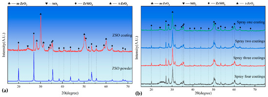
Figure 3.
XRD patterns: (a) ZrSiO4 raw material and ZSO coating, and (b) ZSO coatings after 1 to 4 cycles of APS.
As illustrated in Figure 3b, the phase composition of the ZSO-coated sample demonstrates remarkable stability with increasing APS cycle counts. Notably, the absence of detectable C diffraction peaks confirms the adequacy of the coating thickness. Furthermore, a systematic enhancement in the intensity of the amorphous SiO2 peak at 2Theta ≈ 25° is observed with progressive spraying cycles. This phenomenon can be attributed to the augmented generation of SiO2 resulting from ZrSiO4 dissociation during the coating thickness accumulation process.
Figure 4 presents the surface microstructure and EDS analysis results of the ZSO coating. Figure 4a,c indicate that the ZSO-coated surface is predominantly constituted of numerous spherical particles. The growth and stacking of these small spherical particles result in a relatively rough surface. In Figure 4b, several “small black dots” can be discerned on the surfaces of these spherical particles. An EDS analysis of these “small black dots” indicates that the main elemental composition is C. It can be inferred that this C originated prior to the APS process, during which ZrSiO4 powder, deionized water, and an organic binder were amalgamated to form a suspension. This suspension was subsequently processed through an atomizer to generate fine liquid droplets. Following atomization, the droplets underwent heating and drying, resulting in the formation of spherical composite powders. During the cooling phase after APS, C from the organic compounds precipitates onto the surfaces of these spherical particles. In Figure 4d, it is apparent that some spherical particles on the ZSO-coated surface have been impacted by molten droplets, resulting in splattering that exposes the internal morphology of the small particles. EDS analysis by randomly selecting different positions of spherical particles shows that Zr is the main component of the particles, and a small amount of C is detected.
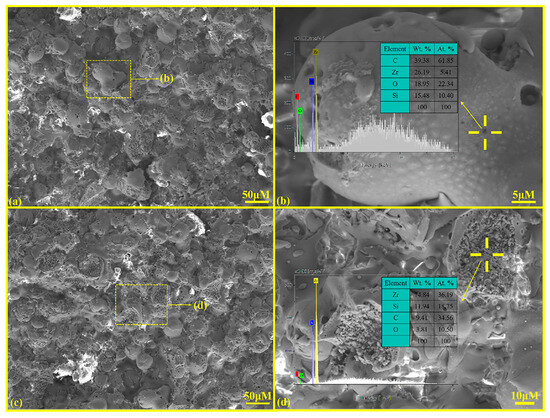
Figure 4.
SEM and EDS analysis of ZSO coating: (a) surface morphology; (b) high-magnification of “yellow frame” in (a); (c) surface morphology; and (d) high-magnification of “yellow frame” in (c).
Figure 5 presents the cross-sectional microstructures of the ZSO coating after different spraying times, with magnified images and their EDS mapping results as insets. Figure 5a,f,k,o show that the gray-white ZSO coating thickness increases from 74.5 μm to 225.0 μm as spraying times progress from one to four, becoming more continuous, uniform, dense, crack-free, and strongly adhered to the substrate with an embedded interfacial structure. Figure 5c,h,m,q reveal small C inclusions in the ZSO coating, resulting from the organic decomposition during plasma spraying.

Figure 5.
Cross-sectional microstructure of ZSO coating: (a) single-layer spray coating; (b) high magnification image of (a); (c–e) distribution maps of C, Zr, and O elements in (b); (f) double-layer spray coating; (g) high magnification image of (f); (h–j) distribution maps of C, Zr, and O elements in (g); (k) triple-layer spray coating; (l) high magnification image of (k); (m,n) distribution maps of C and Zr elements in (l); (o) quadruple-layer spray coating; (p) high magnification image of (o); (q–s) distribution maps of C, Zr, and O elements in (p).
As illustrated in Figure 6b, when the spraying frequency is increased to five times, cracks develop at the interface between the ZSO coating and the C/C substrate. This phenomenon is attributed to the internal stress within the ZSO coating reaching a critical threshold, which promotes particle agglomeration and subsequently diminishes the binding strength between the ZSO coating and the C/C, ultimately leading to interfacial cracking. In contrast, the coating sample subjected to four spraying passes does not display any signs of interfacial cracking, as depicted in Figure 6a. Comparative experiments revealed that the maximum coating thickness can attain 240 μm; within the thickness range of 154 μm to 240 μm, the ZSO coating exhibits optimal encapsulation performance. Consequently, ZSO coatings within this thickness range were selected for further study.
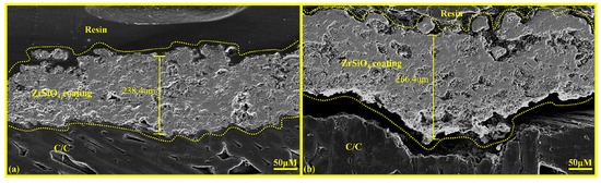
Figure 6.
Cross-sectional microstructural morphology of ZSO coating: (a) coating sprayed four times, and (b) coating sprayed five times.
3.2. Preheating Treatment of ZSO Coating
Research conducted by N.M. Rendtorff et al. demonstrates that thermal treatment can significantly improve the thermal stability of ZSO coatings [22,23]. In light of this finding, the present study implemented annealing processes at 1500 °C and 1600 °C for a duration of 2 h. The objective was to examine how such thermal treatments affect the densification of the ZSO coating developed in this research.
Figure 7 shows the cross-sectional microstructure and surface XRD patterns of the ZSO coating under different heat treatment conditions. Figure 7a shows the microstructural morphology of the ZSO coating prior to heat treatment, revealing a significant number of pores in the cross-section of the untreated ZSO coating. These pores can allow Si, SiO, and SiO2 vapors to penetrate into the C/C substrate, leading to corrosion. Figure 7b displays the cross-sectional diagram of the ZSO coating after heat treatment at 1500 °C, where it is evident that the number of pores within the ZSO coating decreases. This phenomenon occurs due to the reaction between part of the ZrO2 and SiO2 in the ZSO coating, which produces ZrSiO4. The ZrSiO4 then combines with the C precipitated from the organic material, forming a mixture that effectively fills the cracks and pores in the ZSO coating. Figure 7c illustrates the cross-sectional diagram of the ZSO coating after heat treatment at 1600 °C. At this temperature, a volume reduction occurs as ZrO2 reacts with SiO2 to form ZrSiO4. As a consequence, the originally dense coating, primarily composed of ZrO2 and SiO2, is replaced by a relatively loose and porous coating predominantly composed of ZrSiO4.
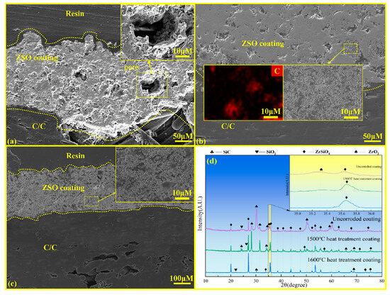
Figure 7.
Cross-sectional microstructural and surface XRD analysis of ZSO coating: (a) without heat treatment; (b) heat treatment at 1500 °C; (c) heat treatment at 1600 °C; and (d) XRD patterns under different treatments.
The different outcomes of the same reaction on the ZSO coating can be primarily attributed to the variation in the heat treatment temperature. According to the XRD spectrum in Figure 7d, after heat treatment at 1500 °C, the diffraction peaks of ZrSiO4 increase, while those of ZrO2 decrease. However, ZrO2 remains the dominant phase. This indicates that after annealing at 1500 °C, only a small amount of ZrO2 reacts with SiO2, and the coating remains predominantly composed of ZrO2. Meanwhile, the ZrSiO4 formed during the reaction effectively combines with the C precipitated from the organic material in the coating, filling the pores. In contrast, after heat treatment of the ZSO coating at 1600 °C, ZrSiO4 becomes the dominant phase, indicating that a significant amount of ZrO2 reacts with SiO2 in the coating. The larger volume of ZrO2 reacts with SiO2 to form the smaller volume ZrSiO4, resulting in a looser and porous ZSO coating [24,25]. Therefore, it is essential to perform heat treatment of the ZSO coating at 1500 °C following the spraying process.
3.3. Corrosion Resistance of ZSO-Coatings Against Si and Its Oxides
3.3.1. Corrosion Resistance of ZSO-Coating Against Si
Figure 8 presents the XRD spectra of C/C substrates with and without ZSO coating after 4 h of Si corrosion. The surface of the uncoated C/C primarily consists of C, SiC, and residual Si phases, with SiC presenting the predominant peak. This result indicates that, at a temperature of 1500 °C, the C/C substrate reacts rapidly upon contact with Si, leading to the formation of a significant amount of SiC. In contrast, after Si corrosion, the primary peak of the ZSO coating remains ZrSiO4, with the detection of C, SiC, and a handful of residual Si. The C originates from the decomposition of organic components in the coating, while the generation of SiC results from the reaction between Si and the C released from these organic materials. The following are the phase reaction equations at 1500 °C:
C(s) + Si(g)→SiC(s)
Figure 8.
XRD patterns of ZSO coating and uncoated C/C substrate following 4 h of Si corrosion.
Figure 9 presents the cross-sectional SEM graphics and EDS analysis results for both uncoated and ZSO-coated samples after 4 h of Si corrosion. The white substance observed on the surface in Figure 9a corresponds to residual Si. In contrast, Figure 9e shows no residual Si on the surface. This is caused by the significant difference in the coefficients of thermal expansion between the ZSO-coated sample and the residual Si, which promotes the separation of the residual Si from the coating surface. Upon cooling, the Si can be removed from the surface. In industrial applications, this helps prevent the malignant accumulation of Si on the coating surface, thereby protecting carbon-based thermal protection materials. As shown in Figure 9f–i, the Si elements did not penetrate the coating to reach the interior of the C/C, which aligns with the findings from the XRD analysis in Figure 8. This result confirms that the SiC formed on the coating surface is produced by the reaction between Si and the C released from the organic material in the coating. A comparison of Figure 9b,g indicates that the uncoated C/C matrix experienced Si vapor infiltration through surface pores during the corrosion process, leading to significant Si accumulation within the C/C. After cooling, this accumulation hindered the normal contraction of the carbon fibers, leading to matrix cracking. The reaction between the C/C surface and Si produced a SiC layer characterized by high hardness and brittleness, ultimately damaging the surface of the C/C and reducing its operational lifespan. In contrast, the ZSO coating exhibited no signs of Si infiltration, demonstrating excellent adhesion between the ZSO coating and the C/C. Therefore, the ZSO coating effectively prevents Si penetration and provides significant resistance to Si corrosion.
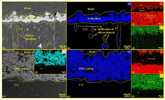
Figure 9.
Cross-sectional SEM images and EDS analysis of uncoated and ZSO coating after 4 h of Si corrosion: (a) micrographs of C/C; (b–d) elemental mapping of Si, C and O corresponding to (a); (e) micrographs of the ZSO coating; (f–i) elemental mapping of Zr, Si, C and O corresponding to (e).
3.3.2. Corrosion Resistance of ZSO Coating Against SiO
Figure 10 presents the XRD spectra of C/C substrates with and without ZSO coating after 4 h of SiO corrosion. As illustrated in Figure 10, the uncoated C/C substrate surface mainly consists of C, SiC, Si, and SiO2 phases, with C being the dominant component. This phenomenon arises from the inherent instability of SiO: at 1500 °C, part of the SiO vapor evaporates, while the rest undergoes disproportionation upon cooling, forming Si and SiO2. Consequently, the C/C surface exhibits Si and SiO2 but no residual SiO. The formed Si and SiO2 further react with C, resulting in the generation of a limited amount of SiC. In contrast, for the ZSO coating, the primary peak in the XRD patterns remains ZrSiO4 after SiO corrosion, indicating the stability of the coating’s phase. In addition, SiC was found in the XRD pattern, and the source of C was the same as the analysis of Si corroding the ZSO coating in Figure 8. Therefore, the synthesis of SiC results from the reaction between Si and SiO2, which are produced by SiO disproportionation, and C released by organic compounds in the coating. The following are the phase reaction equations at 1500 °C:
2SiO(g)→Si(g) + SiO2(g)
C(s) + Si(g)→SiC(s)
3C(s) + SiO2(g)→SiC(s) + 2CO(g)
Figure 10.
XRD patterns of ZSO coating and uncoated C/C substrate following 4 h of SiO corrosion.
Figure 11 presents the cross-sectional SEM diagrams and EDS analysis of C/C substrates with and without a ZSO coating after 4 h of SiO corrosion. According to the results shown in Figure 11e–g,i, SiO did not penetrate the coating to reach the interior of the C/C. This confirms that the SiC observed on the coating surface in Figure 10 is formed by the reaction between C released from the precipitation of organic compounds in the coating of Si and SiO2 generated from the disproportionation of SiO.
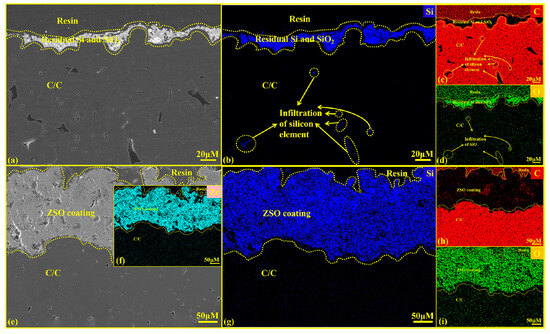
Figure 11.
Cross-sectional SEM images and EDS analysis of uncoated and ZSO coating after 4 h of SiO corrosion: (a) micrographs of C/C; (b–d) elemental mapping of Si, C and O corresponding to (a); (e) micrographs of the ZSO coating; (f–i) elemental mapping of Zr, Si, C and O corresponding to (e).
Figure 11a shows a layer of grayish-white material on the C/C surface, resulting from the Si and SiO2 produced by the disproportionation of SiO during the gradual cooling in the furnace. Figure 11b–d indicates that SiO vapor enters the C/C through surface pores and undergoes disproportionation during the slow cooling process, reacting with C to form SiC. This reaction disrupts the internal structure of the C/C, and the SiC layer formed upon cooling hinders the normal contraction of the carbon fibers, leading to cracking in the substrate and the formation of a hard, brittle SiC on the surface. Ultimately, this will degrade the C/C and reduce its service life. Figure 11e shows that no grayish-white Si and SiO2 are present on the ZSO-coated surface. This is because of the large disparity in the coefficients of thermal expansion between the Si and SiO2 mixture and the ZSO coating, causing them to separate naturally during cooling. After corrosion, the ZSO coating shows no significant changes and adheres well to the substrate. Figure 11f–i indicates that no Si element was detected within the C/C substrate, confirming that throughout the corrosion process, SiO vapor did not penetrate the ZSO coating, thereby demonstrating the effectiveness of the ZSO coating in preventing SiO corrosion of the substrate.
3.3.3. Corrosion Resistance of ZSO Coating Against SiO2
Figure 12 presents the XRD spectra of C/C substrates, both with and without a ZSO coating, after 4 h of SiO2 corrosion. The surface phases of the uncoated C/C mainly include C, SiO2, and SiC, with the dominant peak corresponding to C. This suggests that a reaction occurred between C/C and SiO2 at 1500 °C, leading to the formation of a handful of SiC. Similar to the corrosion of the ZSO coating by Si and SiO, the SiC phase is also detected on the surface of the ZSO coating after SiO2 corrosion, with the C source being the same. Specifically, SiO2 reacts with the C precipitated by the organic matter in the coating to form a small amount of SiC. The following are the phase reaction equations at 1500 °C:
3C(s) + SiO2(g)→SiC(s) + 2CO(g)
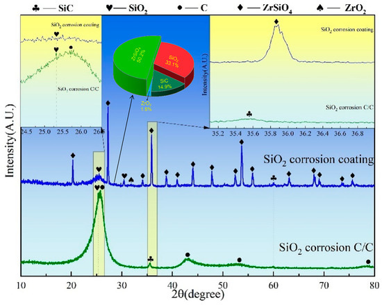
Figure 12.
XRD patterns of ZSO coating and uncoated C/C substrate following 4 h of SiO2 corrosion.
Figure 13 presents a cross-sectional SEM diagram and the EDS analysis of the C/C substrates with and without a ZSO coating after 4 h of SiO2 corrosion. Figure 13e–i show that SiO2 did not penetrate the ZSO coating into the C/C substrate. This supports the analysis results in Figure 12, which show that the SiC on the ZSO-coated surface formed from the reaction between C, derived from organic compound precipitation, and SiO2.
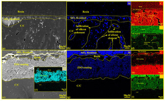
Figure 13.
Cross-sectional SEM images and EDS analysis of uncoated and ZSO-coated samples after 4 h of SiO2 corrosion: (a) micrographs of C/C; (b–d) elemental mapping of Si, C and O corresponding to (a); (e) micrographs of the ZSO-coated samples; (f–i) elemental mapping of Zr, Si, C and O corresponding to (e).
In Figure 13a, a layer of dispersed grayish-white material, identified as residual SiO2, is visible on the C/C surface. The significant difference in thermal expansion coefficients between SiO2 and the C/C, SiO2 creates a shell-like coating upon cooling, which can be easily peeled off with minimal force. After peeling, a small amount of SiO2 remains adhered to the substrate, resulting in the microstructure depicted in Figure 13a–d illustrates that molten SiO2 and its vapor penetrate the interior of the C/C substrate through surface pores, leading to the formation of numerous corrosion zones. Upon cooling, the presence of SiO2 prevents the carbon fibers from contracting normally, resulting in substrate cracking. The C/C surface produces a hard yet brittle SiC layer, further compromising the integrity of the C/C material and reducing its service life.
From Figure 13e, it can be observed that the coating is separated from the residual SiO2 by a cold embedding resin. This separation occurs because of the large difference in thermal expansion coefficients between the ZSO coating and SiO2, causing SiO2 to detach from the coating during cooling. This indicates a weak binding force between SiO2 and the coating, which does not affect the adhesion force between the ZSO coating and the C/C substrate. Consequently, residual SiO2 can be easily removed from the coating surface after cooling. Figure 13f–i shows that Si was not detected within the C/C substrate, suggesting that throughout the SiO2 corrosion process, SiO2 vapor did not penetrate the ZSO coating, further confirming the superior corrosion resistance of the ZSO coating to SiO2.
4. Conclusions
This study addresses the issue of siliconization and the subsequent degradation of the service performance of C/C composites in high-temperature, silicon-rich environments. The research integrates coating protection technology by applying plasma spraying to fabricate ZSO coatings and evaluates their silicon corrosion resistance at 1500 °C. Based on the experimental results and analysis, the following conclusions are drawn:
- (1)
- The ZSO coatings, fabricated using atmospheric plasma spraying, exhibit optimal performance within a thickness range of 154–240 μm. After annealing at 1500 °C, significant reductions in crack density and porosity are observed, resulting in enhanced densification.
- (2)
- In an argon environment, the ZSO coatings demonstrate excellent resistance to silicon corrosion after 4 h of exposure at 1500 °C to Si, SiO, and SiO2. The coatings effectively prevent the penetration of silicon into the C/C substrate, with no permeable cracking, while maintaining strong interfacial adhesion with the C/C substrate.
Author Contributions
Writing—original draft preparation, formal analysis and data curation, methodology, and data analysis H.Y. (Haijiang Yu); Writing—review and editing, supervision and validation, H.Y. (Huiyong Yang); Visualization and investigation, Software, D.W., Y.X., L.W. and Z.C.; Methodology, Formal analysis, W.L., R.L. and J.H. All authors have read and agreed to the published version of the manuscript.
Funding
The work reported here was funded by the Jiangxi Provincial Natural Science Foundation (20232BAB204019), the National Natural Science Foundation of China (52272063), and the Aeronautical Science Foundation of China (2024Z055056001).
Institutional Review Board Statement
Not applicable.
Informed Consent Statement
Not applicable.
Data Availability Statement
The data presented in this study are available upon request from the corresponding author.
Conflicts of Interest
The authors declare no conflicts of interest. The funders had no role in the design of the study; in the collection, analyses, or interpretation of data; in the writing of the manuscript; or in the decision to publish the results.
References
- Zhao, Z.; Li, K.; Kou, G.; Li, W. Comparative research on cyclic ablation behavior of C/C-ZrC-SiC and C/C-ZrC composites at temperatures above 2000 °C. Corros. Sci. 2022, 206, 110496. [Google Scholar] [CrossRef]
- Zhao, Z.; Li, K.; Li, W. Ablation behavior of ZrC-SiC-ZrB2 and ZrC-SiC inhibited carbon/carbon composites components under ultrahigh temperature conditions. Corros. Sci. 2021, 189, 109598. [Google Scholar] [CrossRef]
- Li, J.; Zhang, Y.; Zhao, Y.; Zou, Y.; Lv, J.; Li, J. A novel (Hf1/3Zr1/3Ti1/3)C medium-entropy carbide coating with excellent long-life ablation resistance applied above 2100 °C. Compos. Part B Eng. 2023, 251, 110467. [Google Scholar] [CrossRef]
- Teng, L.; Shi, X.-H.; Wang, H.-H.; Li, W.; Yin, X.-M.; Li, H.-J. A new method to improve the laser-ablation resistance of Si-SiC coating on C/C composites: Laser cladding. J. Eur. Ceram. Soc. 2022, 42, 6425–6434. [Google Scholar] [CrossRef]
- Zhu, X.; Ou, C.; Li, T.; Zhang, Y.; Lv, J.; Chen, R. HfSi2-HfB2-SiC coating prepared at low temperature to protect SiC-coated C/C composites against oxidation at 1473–1973K. Ceram. Int. 2024, 50, 13490–13499. [Google Scholar] [CrossRef]
- Rendtorff, N.M.; Garrido, L.B.; Aglietti, E.F. Effect of the addition of mullite–zirconia to the thermal shock behavior of zircon materials. Mater. Sci. Eng. A 2008, 498, 208–215. [Google Scholar] [CrossRef]
- Rendtorff, N.M.; Grasso, S.; Hu, C.; Suarez, G.; Aglietti, E.F.; Sakka, Y. Dense zircon (ZrSiO4) ceramics by high energy ball milling and spark plasma sintering. Ceram. Int. 2012, 38, 1793–1799. [Google Scholar] [CrossRef]
- Kaiser, A.; Lobert, M.; Telle, R. Thermal stability of zircon (ZrSiO4). J. Eur. Ceram. Soc. 2008, 28, 2199–2211. [Google Scholar] [CrossRef]
- Rendtorff, N.M.; Garrido, L.B.; Aglietti, E.F. Thermal shock resistance and fatigue of Zircon–Mullite composite materials. Ceram. Int. 2011, 37, 1427–1434. [Google Scholar] [CrossRef]
- Drexler, J.M.; Shinoda, K.; Ortiz, A.L.; Li, D.; Vasiliev, A.L.; Gledhill, A.D.; Sampath, S.; Padture, N.P. Air-plasma-sprayed thermal barrier coatings that are resistant to high-temperature attack by glassy deposits. Acta Mater. 2010, 58, 6835–6844. [Google Scholar] [CrossRef]
- Feuerstein, A.; Knapp, J.; Taylor, T.; Ashary, A.; Bolcavage, A.; Hitchman, N. Technical and Economical Aspects of Current Thermal Barrier Coating Systems for Gas Turbine Engines by Thermal Spray and EBPVD: A Review. J. Therm. Spray Technol. 2008, 17, 199–213. [Google Scholar] [CrossRef]
- Yao, D.-J.; Li, H.-J.; Wu, H.; Fu, Q.-G.; Qiang, X.-F. Ablation resistance of ZrC/SiC gradient coating for SiC-coated carbon/carbon composites prepared by supersonic plasma spraying. J. Eur. Ceram. Soc. 2016, 36, 3739–3746. [Google Scholar] [CrossRef]
- Rosado, E.; Cañas, E.; Recio, P.; Sánchez, E.; Moreno, R. ZrSiO4/ZrO2 thermal barrier coatings produced by suspension plasma spraying. J. Eur. Ceram. Soc. 2024, 44, 460–470. [Google Scholar] [CrossRef]
- Salam, M.Y.A.; Ogunmuyiwa, E.N.; Manisa, V.K.; Yahya, A.; Badruddin, I.A. Enhancing phase charac-terization of AlCuCrFeNi high entropy alloys using hybrid machine learning models: A comprehensive XRD analysis. J. Mater. Res. Technol. 2025, 36, 592–605. [Google Scholar] [CrossRef]
- Li, Y.; Zeng, F.; Gao, B.; Chen, H.; Zhang, F.; Gu, Y. Durable anti-oxidation mechanism and failure analysis of the ZrSiO4 compound glass coating for carbon/carbon composites. Surf. Coat. Technol. 2018, 349, 233–241. [Google Scholar] [CrossRef]
- Ramaswamy, P.; Seetharamu, S.; Varma, K.B.R.; Rao, K.J. Thermal barrier coating application of zircon sand. J. Therm. Spray Technol. 1999, 8, 447–453. [Google Scholar] [CrossRef]
- Rudajevová, A. Thermal properties of plasma-sprayed ZrSiO4 material. Surf. Coat. Technol. 1994, 64, 47–51. [Google Scholar] [CrossRef]
- Butterman, W.C.; Foster, W.R. Zircon Stability and the ZrO2-SiO2 Phase Diagram. Am. Mineral. 1967, 52, 880–885. [Google Scholar]
- McPherson, R.; Shafer, B.V. Spherulites and phase separation in plasma-dissociated zircon. J. Mater. Sci. 1984, 19, 2696–2704. [Google Scholar] [CrossRef]
- Garvie, R.C. Stabilization of the tetragonal structure in zirconia microcrystals. J. Phys. Chem. 1978, 82, 218–224. [Google Scholar] [CrossRef]
- Nagarajan, V.S.; Rao, K.J. Crystallization studies of ZrO2−SiO2 composite gels. J. Mater. Sci. 1989, 24, 2140–2146. [Google Scholar] [CrossRef]
- Suzuki, M.; Sodeoka, S.; Inoue, T. Structure Control of Plasma Sprayed Zircon Coating by Substrate Preheating and Post Heat Treatment. Mater. Trans. 2005, 46, 669–674. [Google Scholar] [CrossRef]
- McPherson, R.; Shafer, B.V.; Wong, A.M. Zircon-Zirconia Ceramics Prepared from Plasma Dissociated Zircon. J. Am. Ceram. Soc. 1982, 65, c57–c58. [Google Scholar] [CrossRef]
- Suzuki, M.; Inoue, S.S.L.; Ueno, K. Effect of Heat Treatment on Plasma-Sprayed Zircon (ZrSiO ZrSiO4). Mater. Manuf. Process. 1998, 13, 575–580. [Google Scholar] [CrossRef]
- Rendtorff, N.M.; Suárez, G.; Conconi, M.S.; Singh, S.K.; Aglietti, E.F. Plasma Dissociated Zircon (PDZ) Processing; Influence of the Zr:Si Ratio in the Composition, Microstructure and Thermal Re-Crystallization. Procedia Mater. Sci. 2012, 1, 337–342. [Google Scholar] [CrossRef][Green Version]


Disclaimer/Publisher’s Note: The statements, opinions and data contained in all publications are solely those of the individual author(s) and contributor(s) and not of MDPI and/or the editor(s). MDPI and/or the editor(s) disclaim responsibility for any injury to people or property resulting from any ideas, methods, instructions or products referred to in the content. |
© 2025 by the authors. Licensee MDPI, Basel, Switzerland. This article is an open access article distributed under the terms and conditions of the Creative Commons Attribution (CC BY) license (https://creativecommons.org/licenses/by/4.0/).