Article

MOF-Derived Hollow Dodecahedral Carbon Structures with Abundant N Sites and Co Nanoparticle-Modified Cu Foil for Dendrite-Free Lithium Metal Battery

1
Faculty of Engineering, Huanghe Science & Technology University, Zhengzhou 450006, China
2
School of Materials Science and Engineering, Provincial and Ministerial Co-Construction of Collaborative Innovation Center for Non-Ferrous Metal New Materials and Advanced Processing Technology, Henan University of Science and Technology, Luoyang 471023, China
3
Henan Key Laboratory of Non-Ferrous Materials Science & Processing Technology, Luoyang 471023, China
*
Authors to whom correspondence should be addressed.
Coatings 2025, 15(4), 490; https://doi.org/10.3390/coatings15040490
Submission received: 24 February 2025 / Revised: 16 April 2025 / Accepted: 18 April 2025 / Published: 20 April 2025
(This article belongs to the Special Issue Multilayer Coatings for Nanomaterials: From Synthesis to Applications)

Abstract

:
In this work, hollow dodecahedral carbon structures with abundant N-doping sites and metal nanoparticles (NC-Co-CNTs) based on MOF-derivative materials were designed and prepared as host materials for lithium metal to ensure uniform lithium deposition on a Cu current collector. NC-Co-CNTs have good electrical conductivity, which ensures fast electron transport and Li+ transfer. The carbon nanotubes catalytically derived by Co can promote the uniform distribution of Li+ along the hollow dodecahedral carbon surface and deposition inside the cavity, and the larger electronegativity of N-doped sites and lithophilic sites such as Co nanoparticles can effectively adsorb lithium, inducing the Li+ to be deposited in the form of spherical lithium in a dendrite-free state, inhibiting the growth of dendritic lithium and improving the electrochemical performance of the lithium metal battery. Based on the above advantages, the electrodes of NC-Co-CNT-based symmetric cells present superior cycling performance for more than 1100 h with low overpotential at 1 mAh cm−2/1 mAh·cm−2. Even cycling at high current density of 5 mA cm−2 and high deposition parameters of 5 mAh cm−2, it still cycles for up to 800 h at a relatively low overpotential.

1. Introduction

To meet the demand for advanced energy storage devices with high energy density [1,2,3], metallic lithium metal is considered a very promising anode material for high-energy density rechargeable batteries because of its high theoretical specific capacity (3860 mAh g−1), light weight (0.534 g cm−3), and lowest redox potential (−3.04 V vs. SHE) [4,5,6]. Nevertheless, the loss of active lithium and the rapid growth of lithium dendrites during charge–discharge cycles would lead to sluggish capacity performance and safety risks, which might hinder commercial applications of lithium metal batteries [7,8,9]. The uneven and random lithium plating–stripping on the copper foil with a lithiophobic nature and defect sites during cycling are widely believed to be an important cause of the generated inactive lithium and lithium dendrite growth [10]. Hence, modifying the copper foil with abundant lithium nucleation sites is crucial for regulating the uniform deposition–stripping of lithium during cycling to produce high-performance lithium metal batteries [11]. Among the surface modification strategies, coating the functionalized layers on copper foil is a simple, direct, and effective strategy. Researchers have explored various functionalized coating layers for copper foil to attain nucleation control and deposition uniformity [12,13]. For example, some metals possess strong lithiophilic affinity, such as Au [14,15], Ag [16,17,18], and Zn [19], etc. They could improve the lithiophilicity of copper foil and be beneficial to lithium adsorption and nucleation. To ensure uniform lithium deposition during cycles, lithiophilic metals should be uniformly and firmly dispersed on surface of the copper foil as small particles. For instance, Jung et al. introduced highly periodic Au dot nanopatterns on copper substrates by nanolithography to spatially induce uniform lithium deposition, which resulted in significantly improved cycling performance [20]. In addition, N-containing functional groups can effectively induce uniform lithium deposition [21,22,23]. Zhang [21] et al. designed a nitrogen-doped graphene matrix as a modified layer on Cu foil. The modified layer with abundant lithiophilic N-containing groups facilitated more lithium uniform nucleation and induced Li+ to preferentially deposit itself on the surface of N-doped graphene. Furthermore, Patrike et al. developed a 3D honeycomb boron carbon nitride (HBCN) as a functional scaffold on copper foil [24]. The boron and nitrogen doping, large surface area, and mesoporous structure in the HBCN provided abundant lithium nucleation sites for subsequent dendrite-free lithium growth. Hence, to obtain high-performance lithium metal batteries through engineering coating layers on copper foil, the following conditions need to be met: (1) a mesoporous structure with high surface area inducing uniform lithium deposition and accommodating lithium expansion, (2) evenly distributed defects from element doping providing uniform and abundant lithium nucleation sites, and (3) a conducting matrix facilitating a guided path for Li plating–stripping. A Li metal cell comprising a Li-deposited HBCN as an anode and LFP as a cathode has shown stable performance. However, designing materials with the three advantages as coating layer on copper foil through simple preparation method is still challenging.
Metal–organic frameworks (MOFs) consisting of metal ions and organic ligands have unique properties, such as high porosity and chemical/structural adjustability [25,26]. MOF-derived carbon materials are potential candidates for inducing uniform metal ion plating–stripping and accommodating the volume change of metal plating–stripping during cycling [27,28]. Zeolite imidazole frames ZIF-8 and ZIF-67, a typical class of MOF materials, are composed of zinc (Zn) and cobalt (Co) metal ions, respectively, and are assembled with 2-methylimidazole (2-MeIm) as organic linker to obtain rhombohedral dodecahedron ZIFs with large voids. Kim et al. reported a porous carbon matrix material derived from ZIF-8 to be a promising candidate material for lithium metal storage due to its large pore volume and high electrical conductivity [29]. In this architecture, the presence of Zn atoms increases the host’s lithium affinity and promotes stable lithium metal deposition. Lee et al. reported a bimetallic ZIF-derived carbon material for a lithium metal negative electrode that can regulate the uniform deposition of lithium and presents stable cycling performance of the electrode [30]. In addition, the synergistic effect of lithiophilic sites and carbon nanotubes (CNTs) with high electron conductivity facilitates uniform lithium deposition and then improves the electrochemical performance of lithium metal batteries [31,32,33].
Inspired by the above work, MOF-derived Co-embedded and N-doped carbon architectures (NC-Co-CNTs) were designed as coating layers on copper foil in this work. The embedded Co nanoparticles were used as active sites to guide the deposition of lithium through inducing the deposition of Li+ at the nanoscale. In addition, the hollow structure regulated the uniform deposition of lithium metal as spherical lithium with small nucleation overpotential, effectively avoiding the generation of dendritic lithium. The results show that the NC-Co-CNT-modified copper foil presents improved electrochemical performance with a relatively low overpotential for up to 800 h when cycling at high current density of 5 mA·cm−2. This work provides a promising strategy to develop structurally engineered lithiophilic copper foil for high-energy-density LIBs.

2. Materials and Methods

2.1. Preparation of ZIF-8

Zn(NO3)2·6H2O, dimethylimidazole (2-MeIm), and methanol were used as raw materials without further purification. First, 0.901 g of Zn(NO3)2·6H2O was dissolved in 30 mL of methanol with stirring to form solution A (0.10 mol L−1). Then, 1.005 g of 2-MeIm was dissolved in 20 mL of methanol to form solution B (0.61 mol L−1). Solution B was poured into solution A and subsequently stirred for 30 min. Afterwards, the precipitate was collected after the mixed solution had aged at room temperature for 24 h through centrifugal washing with methanol and dried under vacuum at 60 °C for 12 h. Finally, the ZIF-8 was obtained.

2.2. Preparation of ZIF-8@ZIF-67

First, 0.1 g of ZIF-8 was ultrasound-dispersed into 30 mL methanol, 0.15 g of Co(NO3)2·6H2O was added to the solution, and ultrasound applied for 30 min to form solution C. Then, 0.328 g of 2-MeIm was dissolved in 10 mL methanol solution to form solution D. Solution D was slowly poured into solution C under magnetic stirring, and subsequently aged at room temperature for 24 h. Finally, the precipitate was collected by centrifugal washing with methanol and dried under vacuum at 60 °C for 12 h to obtain the ZIF-8@ZIF-67 composite.

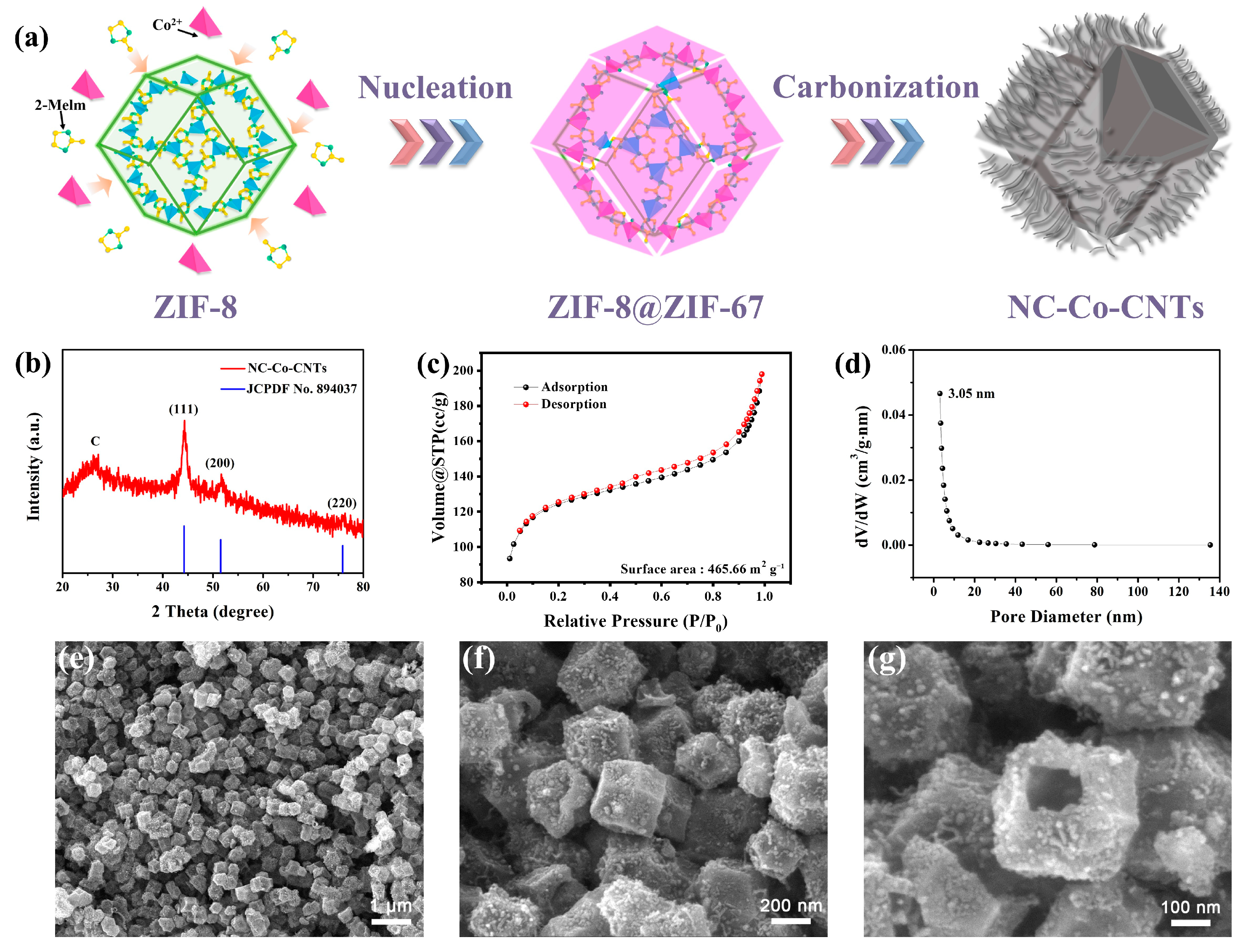
2.3. Preparation of NC-Co-CNTs

The obtained ZIF-8@ZIF-67 composite was transferred to a tube furnace, then heated at 800 °C for 4 h at a heating rate of 2 °C min−1. The product was cooled to room temperature and then ground to obtain NC-Co-CNTs with hollow structure.

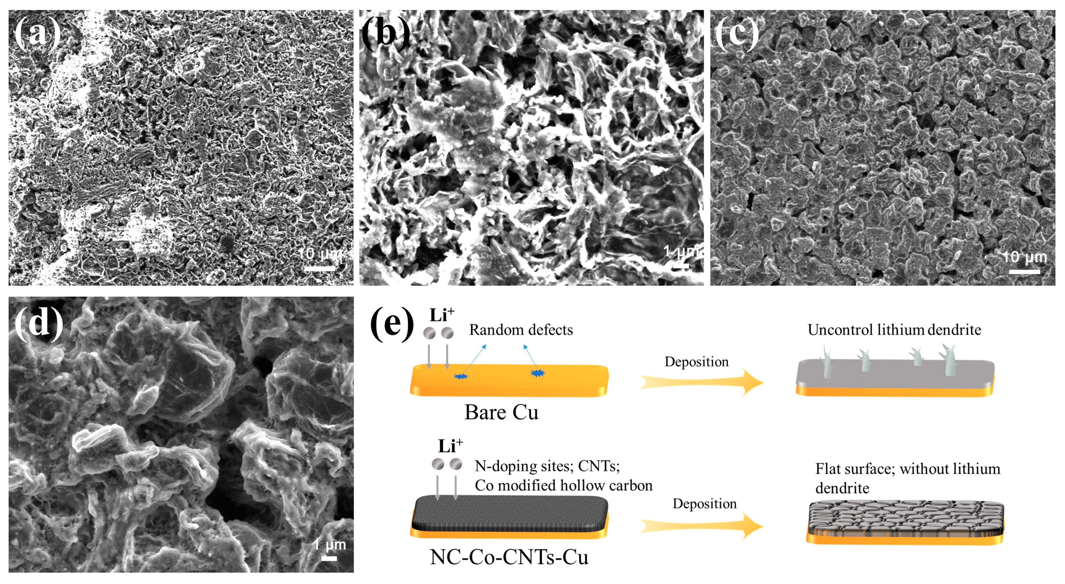
2.4. Preparation of NC-Co-CNT-Modified Copper Foil

The NC-Co-CNTs were dispersed into N-methyl pyrrolidone (NMP) with ultrasonic vibration for 30 min. Polyvinylidene fluoride (PVDF) was added to the above solution with a mass ratio of NC-Co-CNTs to PVDF of 9:1. The uniform seriflux obtained after the magnetic stirring of the mixed solution for 6 h was scraped from the cleaned copper foil and dried in vacuum at 60 °C for 12 h to obtain NC-Co-CNT-modified copper foil (NC-Co-CNT-Cu). For comparison, the bare copper foil (b-Cu) was prepared through washing copper foil with diluted hydrochloric acid and then dried at 60 °C for 12 h.

2.5. Electrochemical Measurements

All electrochemical performances of prepared products were evaluated in CR2032 coin cells assembled in a glove box filled with argon. Lithium bis((trifluoromethyl)sulfonyl)azanide (1 M) dispersed in 1,3-dioxolane (DOL)–1,2-dimethoxyethane (DME) = 1:1 vol% with 1 wt% LiNO3 was used as electrolyte. The Li/NC-Co-CNTs and Li/Cu cells were assembled by NC-Co-CNT-Cu/b-Cu electrodes as working electrodes and lithium foil as counter electrode to evaluate the nucleation overpotential and coulombic efficiency. The prepared electrodes had 10 mAh·cm−2 of lithium deposited on them through electrochemical deposition at a current density of 1 mA·cm−2 (labeled NC-Co-CNT-Li or b-Cu-Li), and then assembled into the symmetric batteries to measure electrochemical behavior of lithium plating and stripping. All electrochemical performances of assembled batteries were tested by the Neware battery test system (BTS-5V20mA, NEWARE TECHNOLOGY LIMITED, Shenzhen, China).

2.6. Characterization

The crystalline structures of the synthesized NC-Co-CNT composites were investigated by XRD (Bruker D8 Advance, Cu Kα radiation). In addition, the microstructure of the NC-Co-CNT composites was characterized by field-emission scanning electron microscopy (FESEM, Gemini SEM 500) and the field emission transmission electron microscope (TEM, JEOL ARM-200F). The Raman spectra were recorded on a JY LABRAM-HR confocal laser micro-Raman spectrometer to study the degree of order of carbon materials in the prepared NC-Co-CNT composites. XPS measurements were conducted on an ESCALAB 250Xi (Thermo-VG Scientific, Waltham, MA, USA) to determine the chemical state of the surface elements of NC-Co-CNT composites. Thermogravimetric analysis (TGA) of the NC-Co-CNT composites was conducted on a Mettler Toledo TGA/SDTA851 thermal analyzer to analyze the carbon content. The specific surface area of samples was examined using the Brunauer–Emmett–Teller (BET) equation based on N2 adsorption–desorption isotherms (Mike ASAP-2460). The roughness of lithium deposits on surfaces of both the b-Cu electrode and NC-Co-CNT-modified Cu electrode was assessed using an optical profilometer (Bruker Contour GT-K 3D, Bruker Nano GmbH, Karlsruhe, Germany). The N and H content in NC-Co-CNTs was analyzed and determined using an oxygen, nitrogen, and hydrogen analyzer (Horiba EMGA-830, HORIBA, Ltd., Kyoto, Japan).

3. Results and Discussion

The synthesis process of NC-Co-CNTs is shown in Figure 1a. The Zn-MOFs were obtained by a simple one-step room-temperature crystallization route using Zn2+ and 2-methylimidazole, and powder X-ray diffraction (XRD) patterns confirmed that these Zn-MOFs presented a crystal structure similar to that of ZIF-8 (Figure S1). The ZIF-8@ZIF-67 composite with core–shell structure was obtained by epitaxial growth at room temperature using similar cell parameters and topological structures of ZIF-8 and ZIF-67 [34]. The corresponding XRD spectrum of the ZIF-8@ZIF-67 composite is shown in Figure S2, which is consistent with that previously reported in the literature [34]. The hollow carbon structure derived from ZIF-8 in the inner core formed through one-step pyrolysis. The abundant N elements from organic ligands were doped into the product during heat treatment. The carbon nanotubes were derived from the outer shell using the catalytic characteristics of Co particles. Finally, the hollow NC-Co-CNTs were obtained after a series of steps through carbonization. The XRD spectrum of hollow NC-Co-CNTs in Figure 1b shows that the characteristic peaks of ZIF-8 and ZIF-67 have completely disappeared. A typical diffraction peak at 26.5° corresponds to the (002) crystalline plane of carbon. The other diffraction peaks at 44.3°, 51.6°, and 75.8° correspond well to the (111), (200), and (220) in the PDF card of the Co metal (JCPDS 89-4037), respectively. The diffraction peak corresponding to the crystal plane (111) was taken as the example to calculate the crystallite size of Co in NC-Co-CNTs. According to Scherrer’s formula (D = Kλ/βcosθ) (D is the average thickness of the grain perpendicular to the direction of the crystal surface, nm; K is the Scherrer constant, K = 0.89; λ is the X-ray wavelength, 0.15418 nm; β is the measured sample diffraction peak half-height width, 1.41°; and θ is the diffraction angle, 22.15°), the crystallite size of Co in NC-Co-CNTs was about 6.2 nm. Figure S3 shows the thermogravimetric analysis curve of NC-Co-CNTs in the air. The weight loss from room temperature to 200 °C was attributed to the loss of adsorbed water in the material (10.31%), and the weight change from 200 to 396 °C was attributed to the oxidation of carbon and Co. Finally, only 34% of the mass of the material was retained. After calculation, the proportion of Co metal in NC-Co-CNTs was about 27.8 wt%. The above results indicate the successful preparation of the NC-Co-CNT composites.
The porous characteristic of NC-Co-CNTs were analyzed by N2 adsorption–desorption tests. Based on the BET method, the adsorption–desorption curves demonstrated a typical type IV curve (Figure 1c), and the specific surface area of NC-Co-CNTs reached 465.66 m2 g−1. The pore size distribution curve shown in Figure 1d indicates porous characteristics of NC-Co-CNTs with mesoporous structure. The pore sizes are mainly concentrated at 3.05 nm. The large specific surface area and abundant pore structure of NC-Co-CNTs are beneficial to the rapid transport of Li+/electrons and accommodate the volume expansion of lithium metal during cycling.
The microstructure of the prepared materials was investigated through SEM experiments. Figure 1e,f show the SEM images of NC-Co-CNTs at different magnifications. It can be clearly seen that the NC-Co-CNT composites present a dodecahedral skeleton structure with a particle size around 300 nm. The particle size distribution and uniformity were further analyzed according to the SEM image of NC-Co-CNTs at low magnification (Figure 1e). Through analyzing and counting particles with Nano Measurer software (Nano Measurer 1.2.5) (Figures S4 and S5), it was determined that the particles of NC-Co-CNTs were mainly distributed in the range of 200 to 400 nm. Most particles were about 300 nm. In addition, a large number of short CNTs were extruded from the surface of the dodecahedron. The formation of short CNTs was mainly attributed to the catalytic action of Co nanoparticles within the material [35]. Carbon nanotubes on the surface of the material built a three-dimensional conductive network and facilitated the fast shuttling of electrons and Li+, which induced the uniform deposition of lithium.
To investigate the degree of order of the carbon structure in the NC-Co-CNT composites, the Raman spectrum of NC-Co-CNTs was obtained, as shown in Figure 2a. The ratio of the intensity of the D peak at 1338 cm−1 (corresponding to the disordered state of carbon) and the G peak at 1589 cm−1 (corresponding to graphitic carbon) was 1.125 (ID/IG), which indicated that the derived carbon presented a highly disordered structure [36,37]. To determine the chemical state of the elements on the surface of NC-Co-CNTs, X-ray photoelectron spectroscopy was performed. Figure 2b shows the full XPS spectrum of the powder, showing the presence of Co 2p, C 1s, N 1s, and O 1s in the material. According to the XPS results in Figure 2b, the Co element in the sample was about 1.67 at% and the N element in the sample was about 12.02 at%. The high-resolution spectra of Co 2p, C 1s, N 1s, and O 1s were further analyzed and fitted by AVANTAGE software (Thermo Avantage v5.9931). First, the binding energy (284.8 eV) was used as the reference peak and calibrated. The aim was to make the peak position of the test spectrum relatively more accurate after correction, which was conducive to the analysis of different chemical states of elements. Figure 2c shows the high-resolution Co 2p XPS spectrum. The characteristic peaks at 778.5 eV and 793.5 eV correspond to the peaks of metallic Co, indicating the successful embedding of Co nanoparticles. In addition, the two characteristic peaks at 780.2 eV and 795.6 eV correspond to Co3+, and the characteristic peaks at 782.45 eV correspond to Co2+. The low-intensity characteristic peaks of Co3+ and Co2+ indicate that partial oxidation reaction occurs on the surface of Co nanoparticles [38]. Based on the high-resolution C 1s spectrum (Figure 2d), C-N bonding can be confirmed from the characteristic peak at 285.56 eV, indicating the successful introduction of N-doping sites as structural defects into the derived carbon. The high-resolution spectrum of N 1s is shown in Figure 2e. There are three obvious peaks in the energy spectrum structure, which are distributed at 398.7 eV (pyridine N), at 400.1 eV (pyrrole N), and at 401.2 eV (tetragonal N), respectively [39]. In addition, according to the areas of fitting peaks, the elemental composition of pyridine N, pyrrole N, and tetragonal N was 7.73%, 2.18%, and 2.11%, respectively. The abundant N-doping sites played effective roles in the stable and uniform deposition of lithium metal on the NC-Co-CNTs [30,40]. Further, we conducted elemental analysis to determine the N and H content using the oxygen, nitrogen, and hydrogen analyzer. The N and H content in the sample was about 1.16 wt% and 0.868 wt% (Table S1). The abundant N and H content could be conducive to the stable and uniform deposition of lithium metal on the NC-Co-CNT-Cu. Figure 2f shows the high-resolution spectrum of O 1s, in which oxygen is mainly chemically bonded with carbon and cobalt in carbon and cobalt nanoparticles to form O-Co bonds at 532.7 eV and O-C bonds at 531.2 eV.
To further confirm that NC-Co-CNTs with hollow structure and carbon nanotubes were obtained after annealing of ZIF-8@ZIF-67, the microstructure and elemental composition of NC-Co-CNTs were characterized in detail by transmission electron microscopy (TEM) and energy-dispersive X-ray spectroscopy (EDS), as shown in Figure 3. In Figure 3a, the center and outer edges of NC-Co-CNTs show obvious light–dark boundaries, which confirm the formation of hollow dodecahedral structures. The formation of the hollow structure also provides the potential for storage of lithium metal and can alleviate the volume expansion of the lithium electrode during cycling. At higher magnification (Figure 3b), it is obvious that a large number of carbon nanotubes have been derived from the exterior of the carbonaceous shell layer and the ends of the carbon nanotubes are coated with metal Co nanoparticles. In addition, some Co nanoparticles are embedded in the dodecahedral carbon skeleton, as shown in the yellow ellipse in Figure 3b.
The derived carbon nanotubes were further analyzed by HRTEM. As shown in Figure 3c, the metal Co nanoparticles are encapsulated in the carbon nanotubes. The lattice fringes with interplanar crystal spacing of 0.34 nm and 0.21 nm correspond to the (002) crystal plane of graphitic carbon and the (111) crystal plane of Co metal, respectively. The SAED pattern in this region is shown in Figure 3d. The two diffraction rings match well with (111) and (200) of Co, indicating the formation of Co metal nanocrystallites. The presence of Co nanoparticles enhanced the interaction between Li metal and NC-Co-CNTs, leading to the uniform deposition of Li metal. Figure 3e(f1–f4) show HAADF-STEM images and distribution of elements (elemental mapping was performed with a spatial resolution of 2 nm). The hollow NC-Co-CNTs contain Co, N, C and O elements, which are evenly dispersed in the carbon skeleton. The complete EDS elemental map of Co, N, C, and O elements in Figure S6 further confirms the uniform distribution of the elements within the structure. The N species in the 2-methylimidazole ligand was introduced into the amorphous carbon structure during pyrolysis, which improved the electrical conductivity of the derived carbon and reduced the nucleation barrier of lithium metal [29].
In order to investigate the deposition behavior of lithium metal on modified copper foils, b-Cu and NC-Co-CNT-modified copper foil (NC-Co-CNT-Cu) were used as working electrodes, and lithium foil was used as a counter electrode to assemble the cells for testing. Lithium metal with a surface capacity of 10 mAh·cm−2 was deposited at a current density of 1 mA·cm−2. The obtained lithium deposition nucleation curve is shown in Figure 4a. Compared with b-Cu, NC-Co-CNT-Cu presented a lower nucleation barrier and nucleation overpotential, indicating that it had better lithium metal affinity. This could be due to the abundant pore structure of NC-Co-CNTs providing enough space for lithium deposition and the introduction of N-doping sites and Co NPs reducing the nucleation barrier of lithium metal. The b-Cu electrode displayed a higher nucleation overpotential, which indicated that lithium nucleation on the b-Cu surface needs to overcome a higher energy barrier, making Li+ deposition on the surface of copper foil more difficult.
When 1 mAh·cm−2 was deposited on b-Cu (Figure 4b), there were more holes on the surface. Through further enlargement of the surface morphology (Figure 4c), it can be seen that some lithium metal was deposited on the b-Cu in the form of lithium dendrite. With the increase in lithium deposition capacity to 3 mAh·cm−2, the dendritic lithium metal gradually grew (Figure 4d,e). It can be seen that the dendritic lithium is more robust and interwoven in the SEM images with higher magnification (Figure 4e). After plating of 10 mAh·cm−2 lithium metal (Figure 4f,g), the Li metal gradually filled part of the space between the lithium dendrites, but the enlarged SEM image still shows a large dendritic lithium structure on the surface of b-Cu. When 1 mAh·cm−2 of lithium metal was deposited on the NC-Co-CNT-Cu, no lithium dendrites were observed (Figure 4h,i). As the deposition capacity increased to 3 mAh·cm−2 (Figure 4j,k), the surface of NC-Co-CNT-Cu remained flat. This could be due to the synergistic effect of active N-doping sites and the Co nanoparticle-modified hollow carbon structure of NC-Co-CNTs inducing and accommodating the deposition of lithium metal. When the deposition capacity reached 10 mAh·cm−2, it can be clearly seen from the SEM images (Figure 4l,m) that the surface of the pole plate was completely covered by lithium metal uniformly and existed in the form of spherical lithium without dendritic lithium. In addition, we further evaluated the roughness of lithium deposits on both surfaces with the optical profilometer (Bruker Contour GT-K 3D). Figures S7 and S8 present optical profiles of the bare copper foil (b-Cu) electrode and the NC-Co-CNT-modified Cu electrode after lithium plating for 10 h at 1 mA·cm−2, respectively. Ra is the mean roughness. Rq is the mean square roughness. The Ra and Rp of the b-Cu electrode were 2.2745 μm and 43.8782 μm, respectively. Conversely, the Ra and Rp of the NC-Co-CNT-modified Cu electrode were 4.1098 μm and 19.4255 μm, respectively. The low Ra and high Rp of the b-Cu electrode after lithium plating could be due to uneven lithium plating and stacked lithium dendrites on random active sites. Based on the uneven outlines in Figure S7 and uniform outlines in Figure S8, these results further demonstrate that the NC-Co-CNTs induced uniform deposition of lithium metal and hindered the formation of lithium dendrites.
Using the b-Cu electrode and NC-Co-CNT electrode for comparison, electrochemical tests were carried out using the constant current test method. The voltage–time curve measured by assembling a half-cell with NC-Co-CNTs and lithium metal foil is shown in Figure 5a. The average Coulombic efficiency(CEave) of Li/NC-Co-CNTs was tested and calculated as per Zhang et al. [41]. First, 5 mAh·cm−2 Li was deposited on the electrode plate, and then the lithium was stripped until the battery voltage was 1 V. Again, 5 mAh·cm−2 Li (QT = 5 mAh·cm−2) was deposited at a current density of 0.5 mA·cm−2, followed by 40 cycles (n = 40) performed with QC = 0.5 mAh·cm−2 at the same current density. Finally, the electrode was stripped to 1 V to obtain the lithium-stripping capacity (QS), and the CEave after “n” cycles was calculated using the following formula: CEave = (QS + nQC)/(QT + nQC). The CEave of NC-Co-CNTs electrodes was calculated to be 98.14%.
To further evaluate the reversibility and kinetics of the lithium metal electroplating–stripping process, a series of b-Cu-Li//b-Cu-Li symmetrical batteries and NC-Co-CNT-Li//NC-Co-CNT-Li symmetrical batteries were tested and compared. Figure 5b shows the voltage distribution curves for the symmetrical batteries cycling at 0.5 mA cm−2 with 1 mAh cm−2 of lithium capacity. The overpotential of the NC-Co-CNT-Li-based symmetrical battery was lower than that of the b-Cu-Li-based symmetrical battery. The overpotential of the NC-Co-CNT-Li-based symmetrical battery could maintain only about 10 mV for 900 h. Figure 5c shows the electrochemical performance of the symmetrical batteries’ cycling at 1 mA·cm−2 with capacity of 1 mAh·cm−2. The overpotential of the NC-Co-CNT-Li battery was about 12 mV after cycling for 1100 h. In sharp contrast, the overpotential of the b-Cu-Li battery fluctuated and increased significantly after cycling for 80 h, which indicated that there were dynamic obstacles in the lithium deposition–stripping process on the surface of b-Cu. During the cycle at a high current density (2 mA·cm−2) (Figure 5d), it was found that the overpotential of both NC-Co-CNT-Li and b-Cu-Li batteries increased. However, the overpotential of the b-Cu-Li cell was more than twice that of the NC-Co-CNT-Li cell. In addition, at a high current density of 5 mA·cm−2 with high lithium deposition capacity of 5 mAh·cm−2, Figure 5e shows that the overpotential of the NC-Co-CNT-Li cell is relatively stable for 96 mV after 800 h of lithium plating–stripping. However, the b-Cu-Li battery reached 270 mV after cycling for 197 h. These results show that the nucleation obstruction of lithium-ion deposition–stripping is greatly reduced through NC-Co-CNT-modified copper foil because of the synergistic effect of the lithiophilic N sites, Co nanoparticles, CNTs, and hollow structure.
The surface state of electrodes in the symmetrical batteries after cycling at 1 mA·cm−2 and 1 mAh·cm−2 was further observed by SEM, as shown in Figure 6. Figure 6a,b show the morphology of the electrode structure of b-Cu-Li. It can be clearly seen that the whole electrode is covered with lithium dendrites and the surface is loose and porous with a large amount of dead lithium. These results indicate that the main reason for the premature failure of the b-Cu-Li-based symmetrical batteries was the large number of lithium dendrites and the nonuniform deposition of lithium metal. Figure 6c,d show the morphology of the NC-Co-CNT-Li-based symmetrical battery after cycling for 1100 h. The surface maintains spherical lithium deposition without obvious dead lithium or lithium dendrites, which proves that the NC-Co-CNTs achieved uniform lithium deposition. The mechanism of Li+ deposition behavior on b-Cu and NC-Co-CNT-Cu is shown in Figure 6e. The N-doping sites and Co nanoparticle-modified carbon structure of NC-Co-CNTs, as uniformly dispersed lithiophilic sites, induced uniform lithium deposition. As a result, the surface of NC-Co-CNT-Cu is flat without any sharp points, which can avoid serious safety risks caused by lithium dendrites. Therefore, the NC-Co-CNT electrode exhibits stable lithium deposition–stripping behavior during cycling, demonstrating excellent electrochemical performance.

4. Conclusions

In this work, hollow dodecahedral carbon structures (NC-Co-CNTs) with abundant lithiophilic sites through pyrolysis of ZIF-8@ZIF-67 were synthesized and applied as coating layer on copper foil for high-performance lithium metal batteries. The graphitic carbon nanotubes catalytically derived by Co can promote the uniform distribution of Li+ along the hollow dodecahedral carbon surface and deposition inside the hollow carbon. The abundant lithiophilic N-doped sites (12.02 at%) and Co nanoparticle-modified carbon with large specific surface (465.66 m2 g−1) induced Li+ to be uniformly deposited on the surface of NC-Co-CNT-modified copper foil, which effectively restrained the growth of dendritic lithium or the formation of dead lithium. Based on the above advantages, the electrodes of the NC-Co-CNT-Li based symmetric battery can cycle for more than 1100 h with low overpotential (about 12 mV) at 1 mAh·cm−2, more than a 10-fold improvement on the b-Cu-Li symmetric battery in cycling life. Even cycling at high current density of 5 mA·cm−2 and high lithium plating–stripping capacity of 5 mAh·cm−2, it maintained a relatively low overpotential (about 96 mV) for up to 800 h. The design of the ZIF-8@ZIF-67 derivative-modified copper foil with abundant lithiophilic sites can promote the further optimization and development of MOF-derived materials for high-performance, dendrite-free lithium metal batteries.

Supplementary Materials

The following supporting information can be downloaded at https://www.mdpi.com/article/10.3390/coatings15040490/s1. Figure S1: X-ray diffraction patterns of ZIF-8; Figure S2: X-ray diffraction patterns of ZIF-8@ZIF-67; Figure S3: Thermogravimetric curve of NC-Co-CNTs in air atmosphere; Figure S4: Analysis of particle size by Nano Measurer software from the SEM image of NC-Co-CNTs at low magnification (Figure 1e); Figure S5: Particle size distribution and uniformity from the results by Nano Measurer software; Figure S6: High-angle annular dark-field scanning transmission electron (HAADF-STEM) image, (b–g) element mapping images of C, Co, N, and O of NC-Co-CNTs; Figure S7: Optical profile of the bare copper foil (b-Cu) electrode after lithium plating for 10 h at 1 mA·cm−2; Figure S8: Optical profile of the NC-Co-CNT-modified Cu electrode after lithium plating for 10 h at 1 mA·cm−2; Table S1: N and H content of NC-Co-CNTs by the oxygen, nitrogen, and hydrogen analyzer.

Author Contributions

Conceptualization, methodology, F.W., H.W., X.R., Y.L. and F.R.; data curation, writing—original draft preparation, writing—review and editing, F.W., H.W. and A.J.; project administration, funding acquisition, F.W. and J.Z. All authors have read and agreed to the published version of the manuscript.

Funding

This work was supported by the Henan Province Science and Technology Research Project (232102241006, 232102231010), Zhengzhou Foundation for Basic Research (grant ZZSZX202412), Materials and Chemical Engineering—Key Disciplines (10th Batch) (0203240012), Postgraduate Education Reform and Quality Improvement Project of Henan Province (YJS2025GZZ63), and Natural Science Foundation of Henan Province (242300420021).

Institutional Review Board Statement

Not applicable.

Informed Consent Statement

Not applicable.

Data Availability Statement

The data presented in this study are available on request from the corresponding author.

Acknowledgments

The authors sincerely thank Haisi Hu for her invaluable assistance in securing financial support for this research. Her expertise and dedication in navigating funding processes were pivotal to the realization of this work. We are deeply grateful for her contribution to ensuring the resources necessary for this study.

Conflicts of Interest

The authors declare no conflict of interest.

References

  1. Xu, Z.-L.; Liu, X.; Luo, Y.; Zhou, L.; Kim, J.-K. Nanosilicon anodes for high performance rechargeable batteries. Prog. Mater. Sci. 2017, 90, 1–44. [Google Scholar] [CrossRef]
  2. Gao, Y.-M.; Liu, Y.; Feng, K.-J.; Ma, J.-Q.; Miao, Y.-J.; Xu, B.-R.; Pan, K.-M.; Akiyoshi, O.; Wang, G.-X.; Zhang, K.-K.; et al. Emerging WS2/WSe2@graphene nanocomposites: Synthesis and electrochemical energy storage applications. Rare Met. 2024, 43, 1–19. [Google Scholar] [CrossRef]
  3. Wu, N.; Shen, J.; Zhou, X.; Li, S.; Li, J.; Liu, G.; Guo, D.; Deng, W.; Yuan, C.; Liu, X.; et al. Constructing Iron Vacancies in Thiospinel FeIn2S4 to Modulate Fe D-Band Center and Accelerate Sodiation Kinetics Enabling High-Rate and Durable Sodium Storage. Adv. Energy Mater. 2025, 2405729. [Google Scholar] [CrossRef]
  4. Liu, D.; Wu, B.; Xu, Y.; Ellis, J.; Baranovskiy, A.; Lu, D.; Lochala, J.; Anderson, C.; Baar, K.; Qu, D.; et al. Controlled large-area lithium deposition to reduce swelling of high-energy lithium metal pouch cells in liquid electrolytes. Nat. Energy 2024, 9, 559–569. [Google Scholar] [CrossRef]
  5. Wang, J.; Zhou, T.; Li, Y.; Luo, Z.; Liao, X.; Wang, X.; Pan, J. Growing mulberry-like copper on copper current collector for stable lithium metal battery anodes. J. Colloid Interface Sci. 2025, 680, 129–138. [Google Scholar] [CrossRef] [PubMed]
  6. Liu, Y.-H.; Wang, F.; Wang, H.-B.; Kong, C.-Y.; Wang, G.-X.; Liu, X.-M.; Liu, Y. Shining Light on Fillers Uniform Dispersion of PVDF/Garnet Composite Electrolytes for High-performance Solid-State Li batteries: Fundamentals, Progress, and Perspectives. Rare Met. 2025. [Google Scholar]
  7. Tarascon, J.M.; Armand, M. Issues and challenges facing rechargeable lithium batteries. Nature 2001, 414, 359–367. [Google Scholar] [CrossRef]
  8. Wang, F.; Gao, J.; Liu, Y.; Ren, F. An amorphous ZnO and oxygen vacancy modified nitrogen-doped carbon skeleton with lithiophilicity and ionic conductivity for stable lithium metal anodes. J. Mater. Chem. A 2022, 10, 17395–17405. [Google Scholar] [CrossRef]
  9. Ma, L.; Cui, J.; Yao, S.; Liu, X.; Luo, Y.; Shen, X.; Kim, J.-K. Dendrite-free lithium metal and sodium metal batteries. Energy Storage Mater. 2020, 27, 522–554. [Google Scholar] [CrossRef]
  10. Lin, D.; Liu, Y.; Cui, Y. Reviving the lithium metal anode for high-energy batteries. Nat. Nanotechnol. 2017, 12, 194–206. [Google Scholar] [CrossRef]
  11. Qiu, J.; Qiu, R.; Mao, Z.; Han, Y.; Madhusudan, P.; Wang, X.; Wang, C.; Qi, C.; Yu, X.; Zeng, S.; et al. A review on copper current collector used for lithium metal batteries: Challenges and strategies. J. Energy Storage 2024, 100, 113683. [Google Scholar] [CrossRef]
  12. Liu, Y.; Xu, Y.; Wang, J.; Sun, Y.; Feng, X.; Xiang, H. Regulated lithium deposition behavior by an artificial coating of Cu foil for dendrite-free lithium metal batteries. Mater. Today Sustain. 2022, 18, 100127. [Google Scholar] [CrossRef]
  13. Zhai, P.; He, Q.; Jiang, H.; Gao, B.; Zhang, B.; Chen, Q.; Yang, Z.; Wang, T.; Gong, Y. Thickness-Dependence of 2D g-C3N4 Artificial Interface Layers on Lithium Metal Deposition. Adv. Energy Mater. 2024, 14, 2302730. [Google Scholar] [CrossRef]
  14. Song, R.; Ge, Y.; Wang, B.; Lv, Q.; Wang, F.; Ruan, T.; Wang, D.; Dou, S.; Liu, H. A new reflowing strategy based on lithiophilic substrates towards smooth and stable lithium metal anodes. J. Mater. Chem. A 2019, 7, 18126–18134. [Google Scholar] [CrossRef]
  15. Li, J.; Ma, Z.; Yang, K.; Zhao, F.; Yang, H.; Wang, H.; He, Y. Laser-Generated Au nanoparticles as lithophilic sites in self-supported film host for anode-free lithium metal battery. J. Colloid Interface Sci. 2025, 678, 578–587. [Google Scholar] [CrossRef]
  16. Yang, K.; Li, L.; Xiao, Y.; Zhang, Q.; Xi, C.; Li, B.; Yu, Y.; Yang, C. Congener-derived template to construct lithiophilic organic-inorganic layer/interphase for high volumetric capacity dendrite-free Li metal batteries. Chin. Chem. Lett. 2024, 35, 108451. [Google Scholar] [CrossRef]
  17. Xia, H.-y.; Wang, D.-l.; Wang, Y.-k.; Fu, Z.-w. Study on Stable Lithiophilic Ag Modification Layer on Copper Current Collector for High Coulombic-Efficiency Lithium Metal Anode. J. Electrochem. Soc. 2023, 170, 060546. [Google Scholar] [CrossRef]
  18. Liu, Z.; Ha, S.; Liu, Y.; Wang, F.; Tao, F.; Xu, B.; Yu, R.; Wang, G.; Ren, F.; Li, H. Application of Ag-based materials in high-performance lithium metal anode: A review. J. Mater. Sci. Technol. 2023, 133, 165–182. [Google Scholar] [CrossRef]
  19. Song, Y.-X.; Lu, W.-Y.; Chen, Y.-J.; Yang, H.; Wu, C.; Wei, W.-F.; Chen, L.-B.; Ouyang, X.-P. Coating highly lithiophilic Zn on Cu foil for high-performance lithium metal batteries. Rare Met. 2022, 41, 1255–1264. [Google Scholar] [CrossRef]
  20. Jung, W.-B.; Chae, O.B.; Kim, M.; Kim, Y.; Hong, Y.J.; Kim, J.Y.; Choi, S.; Kim, D.Y.; Moon, S.; Suk, J.; et al. Effect of Highly Periodic Au Nanopatterns on Dendrite Suppression in Lithium Metal Batteries. ACS Appl. Mater. Interfaces 2021, 13, 60978–60986. [Google Scholar] [CrossRef]
  21. Zhang, R.; Chen, X.-R.; Chen, X.; Cheng, X.-B.; Zhang, X.-Q.; Yan, C.; Zhang, Q. Lithiophilic Sites in Doped Graphene Guide Uniform Lithium Nucleation for Dendrite-Free Lithium Metal Anodes. Angew. Chem. Int. Ed. 2017, 56, 7764–7768. [Google Scholar] [CrossRef] [PubMed]
  22. Yu, W.-J.; Wang, J.; Liu, F.; Cao, Y.; Deng, B.; Li, J.; Xie, H.; Zhang, J.; Tong, H.; Liang, C. Self-supporting heteroatomic S/N co-doped carbon scaffold for robust lithium metal anodes. Carbon 2025, 236, 120106. [Google Scholar] [CrossRef]
  23. Li, P.; Liu, Y.; Bao, X.; Xie, J.; Li, Z.; Li, H.; Ren, Q.; Feng, X.; Hu, Y.; Ma, Y. Nitrogen and fluorine co-doped graphene for ultra-stable lithium metal anodes. Nano Res. 2024, 17, 7212–7220. [Google Scholar] [CrossRef]
  24. Patrike, A.; Karbhal, I.; Wasnik, K.; Torris, A.; Maibam, A.; Krishnamurty, S.; Shelke, M.V. High rate, high temperature, dendrite free plating/stripping of Li in 3-dimensional honeycomb boron carbon nitride to realize an ultrastable lithium metal anode. J. Energy Storage 2023, 68, 107547. [Google Scholar] [CrossRef]
  25. Wang, F.; Liu, Y.; Wei, H.-J.; Li, T.-F.; Xiong, X.-H.; Wei, S.-Z.; Ren, F.-Z.; Volinsky, A.A. Recent advances and perspective in metal coordination materials-based electrode materials for potassium-ion batteries. Rare Met. 2021, 40, 448–470. [Google Scholar] [CrossRef]
  26. Cheng, N.-C.; Wu, Y.C.; Chu, Y.-C.; Hsu, H.-Y.; Chen, W.-C.; Wang, P.-H.; Chang, T.-L.; Chang, J.-K.; Wang, C.-Y. A modulated MOF as a modification layer on copper foil for lithium dendrite suppression. J. Mater. Chem. A 2024, 12, 8474–8486. [Google Scholar] [CrossRef]
  27. Zhuang, Z.; Zhang, F.; Gandla, D.; Jadhav, V.V.; Liu, Z.; Hu, L.; Lu, F.; Tan, D.Q. Metal–Organic Framework-Derived ZnO, N Dually Doped Nanocages as an Efficient Host for Stable Li Metal Anodes. ACS Appl. Mater. Interfaces 2023, 15, 38530–38539. [Google Scholar] [CrossRef]
  28. Zhou, T.; Shen, J.; Wang, Z.; Liu, J.; Hu, R.; Ouyang, L.; Feng, Y.; Liu, H.; Yu, Y.; Zhu, M. Regulating Lithium Nucleation and Deposition via MOF-Derived Co@C-Modified Carbon Cloth for Stable Li Metal Anode. Adv. Funct. Mater. 2020, 30, 1909159. [Google Scholar] [CrossRef]
  29. Kim, J.; Lee, J.; Yun, J.; Choi, S.H.; Han, S.A.; Moon, J.; Kim, J.H.; Lee, J.-W.; Park, M.-S. Functionality of Dual-Phase Lithium Storage in a Porous Carbon Host for Lithium-Metal Anode. Adv. Funct. Mater. 2020, 30, 1910538. [Google Scholar] [CrossRef]
  30. Lee, J.; Choi, S.H.; Qutaish, H.; Hyeon, Y.; Han, S.A.; Heo, Y.-U.; Whang, D.; Lee, J.-W.; Moon, J.; Park, M.-S.; et al. Structurally stabilized lithium-metal anode via surface chemistry engineering. Energy Storage Mater. 2021, 37, 315–324. [Google Scholar] [CrossRef]
  31. Lin, J.; Chen, Z.; Zhao, W.; Han, J.; Chen, B.; Chen, Y.; Liu, Q.; Wu, H.B. A 3D mixed ion-electron conducting framework for dendrite-free lithium metal anodes. Nanoscale 2025, 17, 1282–1288. [Google Scholar] [CrossRef] [PubMed]
  32. Kim, Y.B.; Seo, H.Y.; Senthamaraikannan, T.G.; Cho, J.S.; Kang, Y.C.; Lim, D.-H.; Park, G.D. One-step synthesis of zinc oxide-carbon microspheres decorated with multi-voids and carbon nanotubes via spray pyrolysis for enhanced stability in lithium metal anodes. J. Mater. Sci. Technol. 2024, 192, 95–107. [Google Scholar] [CrossRef]
  33. Sun, X.; Man, J.; Liu, K.; Liu, W.; Sun, J.; Zhang, N.; Zhou, Y.; Geng, Z.; Li, S.; Sun, J. Uniform lithium deposition enabled by a carbon nanotubes framework modified with nanosized ZIF-8 particles for dendrite-free lithium metal anode. Appl. Surf. Sci. 2023, 616, 156474. [Google Scholar] [CrossRef]
  34. Banerjee, R.; Phan, A.; Wang, B.; Knobler, C.; Furukawa, H.; O’Keeffe, M.; Yaghi, O.M. High-Throughput Synthesis of Zeolitic Imidazolate Frameworks and Application to CO2 Capture. Science 2008, 319, 939–943. [Google Scholar] [CrossRef]
  35. Li, Z.; He, H.; Cao, H.; Sun, S.; Diao, W.; Gao, D.; Lu, P.; Zhang, S.; Guo, Z.; Li, M.; et al. Atomic Co/Ni dual sites and Co/Ni alloy nanoparticles in N-doped porous Janus-like carbon frameworks for bifunctional oxygen electrocatalysis. Appl. Catal. B Environ. 2019, 240, 112–121. [Google Scholar] [CrossRef]
  36. Li, Y.; Wang, G.; Yu, H.; Liu, F.; Miao, L.; Wang, L.; Song, Y. Yolk-shell structured ZnO@N-doped carbon with controllable cavity as anode of lithium ion battery. J. Energy Storage 2025, 109, 115143. [Google Scholar] [CrossRef]
  37. Sun, J.; Li, P.; Cheng, Z.; Tang, C.; Du, A.; Zhang, H. Bacteria-Derived Carbon Composite Anode for Highly Durable Lithium-Ion Storage Enabled by Heteroatom Doping and Pore Construction. Adv. Funct. Mater. 2025, 2500154. [Google Scholar] [CrossRef]
  38. Zhao, J.; Konh, M.; Teplyakov, A. Surface chemistry of thermal dry etching of cobalt thin films using hexafluoroacetylacetone (hfacH). Appl. Surf. Sci. 2018, 455, 438–445. [Google Scholar] [CrossRef]
  39. Zang, W.; Sumboja, A.; Ma, Y.; Zhang, H.; Wu, Y.; Wu, S.; Wu, H.; Liu, Z.; Guan, C.; Wang, J.; et al. Single Co Atoms Anchored in Porous N-Doped Carbon for Efficient Zinc−Air Battery Cathodes. ACS Catal. 2018, 8, 8961–8969. [Google Scholar] [CrossRef]
  40. Kim, J.; Young, C.; Lee, J.; Heo, Y.-U.; Park, M.-S.; Hossain, M.S.A.; Yamauchi, Y.; Kim, J.H. Nanoarchitecture of MOF-derived nanoporous functional composites for hybrid supercapacitors. J. Mater. Chem. A 2017, 5, 15065–15072. [Google Scholar] [CrossRef]
  41. Adams, B.D.; Zheng, J.; Ren, X.; Xu, W.; Zhang, J.-G. Accurate Determination of Coulombic Efficiency for Lithium Metal Anodes and Lithium Metal Batteries. Adv. Energy Mater. 2018, 8, 1702097. [Google Scholar] [CrossRef]
Figure 1. (a) Schematic illustration of the preparation of NC-Co-CNTs, (b) X-ray diffraction patterns of NC-Co-CNTs, (c) N2 adsorption–desorption curve and (d) corresponding pore size distribution curve, (eg) SEM images of NC-Co-CNTs at different magnifications.
Coatings 15 00490 g001
Figure 2. (a) Raman spectrum of NC-Co-CNTs, (bf) X-ray photoelectron spectroscopy of NC-Co-CNTs: (b) survey spectrum, (cf) high-resolution spectrum of Co 2p, C 1s, N 1s, and O 1s, respectively.
Coatings 15 00490 g002
Figure 3. Transmission electron microscopy images of NC-Co-CNTs: (a,b) TEM images, (c) HRTEM image, (d) selected area electron diffraction (SAED) image, (e) high-angle annular dark-field scanning transmission electron microscopy (HAADF-STEM) image, (f1f4) element mapping images of Co, N, C, and O of NC-Co-CNTs.
Coatings 15 00490 g003
Figure 4. (a) Lithium metal nucleation overpotential profiles of bare copper foil (b-Cu) and NC-Co-CNT-modified Cu, (bm) SEM of b-Cu and NC-Co-CNT-modified Cu electrodes at current density of 1 mA·cm−2 for different plating times: (b,c) and (h,i) 1 h, (d,e) and (j,k) 3 h, (f,g) and (l,m) 10 h.
Coatings 15 00490 g004
Figure 5. Electrochemical performance. (a) Voltage–time plot of NC-Co-CNT-modified Cu. (b) Galvanostatic charge–discharge profiles of b-Cu-Li and NC-Co-CNT-Li symmetric cells at 0.5 mA·cm−2 and 1 mAh·cm−2. The insets are the enlarged voltage–time profiles at different hours. (ce) Galvanostatic charge–discharge profiles of b-Cu-Li and NC-Co-CNT-Li symmetric cells: (c) 1 mA·cm−2, 1 mAh·cm−2, (d) 2 mA·cm−2, 1 mAh·cm−2, (e) 5 mA·cm−2, 5 mAh·cm−2.
Coatings 15 00490 g005
Figure 6. Comparison of SEM images of NC-Co-CNT-modified Cu electrodes and b-Cu-Li electrodes after cycling at 1 mA·cm−2 and schematic illustrations of lithium metal deposition mechanisms: (a,b) b-Cu-Li electrodes after the battery’s failure, (c,d) NC-Co-CNT-modified Cu electrode after cycling for 1100 h, (e) schematic illustration of lithium metal deposition mechanisms on b-Cu and NC-Co-CNT-modified Cu.
Coatings 15 00490 g006
Disclaimer/Publisher’s Note: The statements, opinions and data contained in all publications are solely those of the individual author(s) and contributor(s) and not of MDPI and/or the editor(s). MDPI and/or the editor(s) disclaim responsibility for any injury to people or property resulting from any ideas, methods, instructions or products referred to in the content.

