Article

Research on the Formation Behaviour and Tribological Service Mechanism of Ni-Based Composite Coatings Prepared by Thermal Spraying Assisted with Alternating Current Magnetic Field

1
Avic Harbin Aircraft Industry Group Co., Ltd., Harbin 150060, China
2
National-Defense Technology Industrial Resin-Based Structural Composite Technology Application-Innovation Center, Harbin 150060, China
3
Heilongjiang Aviation Composite Engineering Technology Research Center, Avic Harbin Aircraft Industry Group Co., Ltd., Harbin 150060, China
4
School of Materials Science and Chemical Engineering, Harbin University of Science and Technology, Harbin 150080, China
*
Authors to whom correspondence should be addressed.
Coatings 2025, 15(5), 496; https://doi.org/10.3390/coatings15050496
Submission received: 11 February 2025 / Revised: 1 April 2025 / Accepted: 3 April 2025 / Published: 22 April 2025

Abstract

:
In this paper, an alternating current (AC) magnetic field-assisted device was employed to enhance the preparation process of supersonic plasma spraying coatings. The phase structure and mechanical service characteristics of the five types of coatings were tested. The research found that the porosity of the coating decreased from 3.93% to 1.58%, the hardness increased from 702.88 to 921.12 HV, the bonding strength increased from 26 MPa to 38.3 MPa, and the tribological coefficient decreased from 0.6859 to 0.4670. The mechanism is that the AC magnetic field enhances the internal structure of the coating through electromagnetic stirring, electromagnetic oscillation and other effects. It also stirs the solidification process of the powder particles, improves the melting behaviour of the coating particles at the interface, and enhances the bonding quality of the coating. The improvement of the microstructure and mechanical properties further improves the tribological properties of the coating. At the same time, it is found that the higher the intensity of the AC magnetic field is not necessarily better for the improvement of the coating performance. When the AC magnetic field voltage reaches the peak of the device, the coating formation process is disturbed by the AC magnetic field, and the coating quality formed under the same spraying process is poor. Appropriate control of the AC magnetic field can effectively improve the internal structure and service quality of the coating. This provides a new technical idea and theoretical research basis for the development of advanced equipment surface engineering protection.

Graphical Abstract

1. Introduction

With the development of advanced equipment manufacturing technology, the surface performance of components has received extensive attention, and surface coating protection technology has emerged accordingly [1,2]. Especially during the service of advanced equipment, high-strength and high-wear-resistant coating materials are often required for surface protection design. Currently, Ni-based ceramic phase powders are widely used [3,4]. Due to their own characteristics such as high-temperature oxidation resistance, thermal corrosion resistance, and high wear resistance, they are widely applied in the hot end components of aero engines, crankshafts and connecting rods, as well as gas turbine blades, etc [5].
For the surface protection of equipment components, the common spraying techniques adopted include: Supersonic Plasma Spraying (SPS) [6], Atmospheric Plasma Spraying (APS) [7], High Velocity Oxygen Fuel Spraying (HVOF), Vacuum Plasma Spraying (VPS) [8], and Cold Spraying (CS) [9], etc. Among them, SPS is an upgraded version of techniques such as APS and HVOF. SPS utilizes the special structural design of the Laval nozzle and mainly uses Ar gas for high-temperature (approximately 10,000 K) and high-speed (above 400 m/s) spraying. It has a high heating temperature for the sprayed powder and a fast particle flight speed, enabling the preparation of dense coatings for the entire material system [10]. VPS is an emerging approach for spraying within a vacuum chamber. It is often combined with cold spraying, taking advantage of the low-temperature and aerodynamic advantages of cold spraying to fabricate some low-melting-point powders [11]. Cold spraying and vacuum cold spraying can produce dense coatings due to their high-speed characteristics. However, due to their low processing temperatures, they can only spray highly plastic powders. Particularly for the Ni-based ceramic powders in this study, deposition is nearly impossible. Hence, SPS technology holds distinct advantages in the preparation of Ni-based ceramic coatings.
However, with the continuous changes in the service environment of mechanical equipment, many fields such as aerospace, marine equipment, and industrial machinery require a highly reliable and high-quality surface coating. However, the SPS technology itself has problems such as high porosity of the coating and poor bonding quality of high-temperature powders, which seriously restrict the development of this technology. Especially in the protective application of Ni-based ceramic coatings, the presence of ceramic phases inside constantly interferes with the bonding characteristics of Ni-based powders, resulting in many pores and fine cracks. This is a devastating blow to the wear resistance of the coating. How to further optimize the existing technology has become a hot topic for researchers. After years of research and development, the supersonic plasma spraying technology has reached the characteristics of high temperature and high speed due to its own structural design. To further improve the coating quality, it is more about optimizing the coating from the perspective of external energy field assistance [12]. Among them, magnetic field assistance is widely used in the thermal spraying process due to its advantages such as non-contact and simple device. According to the changes in magnetic induction intensity, magnetic field assistance devices can be divided into three categories: steady magnetic field [13], pulsed magnetic field, and AC magnetic field. These three types of magnetic field strengthening technologies all have their own characteristics. Especially in the supersonic plasma spraying process, they have good effects on the formation behaviour of molten metal particles and the stress homogenization of coating materials. However, the action mechanisms of different types are also quite different. The research group previously used steady magnetic fields and AC magnetic fields to strengthen the supersonic plasma spraying process and conducted in-depth research on their action mechanisms [14,15]. A steady magnetic field is a type of magnetic field where the direction and intensity of the field do not change over time [16]. Previously, the research group designed a steady magnetic field auxiliary device using neodymium iron boron steady magnets, which operates under 100 V. Its advantages include a simple design and convenient adjustment of the magnetic field direction, allowing for surface coating preparation on various complex workpieces [17,18]. The performance of coatings assisted by a steady magnetic field has improved, but the effects have not been particularly significant. This is mainly related to the application of the steady magnetic field. It can adjust the magnetic field intensity and direction to meet the different magnetic field environment requirements of complex solidification experiments. However, the device has some drawbacks, such as a relatively small magnetic field intensity and inability to adjust the field strength [19]. A pulsed magnetic field is a type of magnetic field generated by intermittent pulse currents, which appear intermittently [20]. Both the frequency and intensity of the magnetic field can be adjusted according to the equipment. The research group has conducted in-depth research in this direction previously [13,14]. The greatest advantage of a pulsed magnetic field is that it can provide a high-intensity magnetic field environment and control the magnetic field process parameters through equipment [21]. However, its disadvantages are also obvious. During the operation of the pulsed magnetic field equipment, there will be intermittent periods without a magnetic field. If this occurs at a critical moment when the molten metal is forming during the coating process, the effect of the pulsed magnetic field will be greatly reduced. An AC magnetic field is a type of magnetic field where both the direction and magnetic induction intensity change over time [22,23,24]. When an AC magnetic field is applied during the processing of molten metal, it causes the generation of induced eddy currents within the melt, resulting in electromagnetic stirring and forced convection. These two effects have significant application value in the solidification process of molten powder during supersonic plasma spraying technology, especially in the principle of enhancing the dissipation of pores in the melt. Currently, no scholars have explored the application of AC magnetic fields in assisting supersonic plasma spraying.
Based on this, this paper prepares surface coatings under different field strength variations by using the method of supersonic plasma spraying assisted by AC magnetic field to meet the demanding conditions of high strength and wear resistance for aviation equipment components. By analysing the parameters such as the internal pore distribution, crystal structure, hardness, bonding strength and residual stress of the coatings, the formation mechanism of the supersonic plasma spraying coatings under the action of AC magnetic field is given. Furthermore, the tribological behaviour of the coatings is analysed to reveal the mechanism of improving the comprehensive service performance of the coatings by AC magnetic field. This provides technical support and theoretical basis for the design of high wear-resistant protective coatings on the surface of advanced equipment.

2. Experimental

2.1. Coating Preparation

In this paper, an AC magnetic field-assisted device was utilized for the preparation of supersonic plasma spray coatings. The AC magnetic field was applied at the end of the supersonic plasma spray flame. It played a role in improving the spreading and stacking formation of the sprayed particles. The overall structure of the device is shown in Figure 1a. The magnets were mostly made of high-strength and high-conductivity Cu-Nb alloy and had a pre-set central through-hole for placing the test materials. After designing the AC magnetic field intensity and the winding structure of the wires, the inner diameter of the magnet was set to 100 mm for coating preparation. Subsequently, the number of AC magnet coils and the winding method were determined through the calculation of the magnetic field distribution of the multi-layer solenoid. A voltage of 100–220 V was applied to the magnet through a transformer, with the frequency controlled at 50 Hz. A 100 mm × 100 mm grid paper was placed above the centre of the magnet, and the distribution of the AC magnetic field above the magnet was tested using a Gauss tester (TM-901EXP). The testing procedure was as follows: The sensor of the tester was positioned at the position to be tested on the grid paper, the magnet switch was turned on, the AC magnetic field would constantly fluctuate, but the peak value would be recorded by the tester. After recording the data, the magnet was switched off. The above experiment was repeated at all the positions to be tested on the grid paper. This paper documented the distribution of the AC magnetic field in the area where the sample was located. The results are presented in Figure 1b–d. It can be observed from the figures that the intensity of the AC magnetic field increases with the increase in voltage. The magnetic field is concentrated at the centre position. When the voltage is 220 V, the intensity of the AC magnetic field is the highest, reaching 1015 Gs. Subsequently, supersonic plasma spraying was conducted under different magnetic field intensities. The powder used in the spraying experiment was Ni-based alloy powder, with detailed elemental composition as follows: Ni (Bal.), Cr (15.94 wt%), Fe (4.98 wt%), B (4.23 wt%), Si (4.31 wt%), and C (3.53 wt%). XRD phase analysis was conducted on the powder, and the diffraction peaks are shown in Figure 1b.
After comparison with standard PDF cards, it was found that the main phases in the powder were CrB, Cr3Si, Ni3Si2, and Ni4B3. Among them, B and Si formed metal composite materials with the base Ni, and Cr also formed ceramic-like strengthening phases with B and Si. These composite phases played a role in enhancing the strength of the powder and improving its fluidity. The substrate used was 1045 steel. Before spraying, the substrate surface was sandblasted to increase the surface roughness and thereby enhance the bonding strength of the coating. The sand grain size was 0.5–1.2 mm, and the air pressure was 0.4 MPa. The sandblasted samples were placed on the spraying fixture and subjected to supersonic plasma spraying under different AC magnetic field intensities. The spraying process parameters are listed in Table 1. To explore the influence of the magnetic field, all the spraying process parameters of the coatings were set to the same conditions, and only the magnetic field intensity parameter was changed during the experiment. It is worth noting that the AC magnetic field used in this study was present throughout the spraying process and could enhance the entire supersonic plasma spraying process. For the convenience of subsequent discussion, the samples were named according to the magnet voltage values. The abbreviations for the five samples were: No processing, 100 V, 150 V, 200 V, and 220 V. For other spraying preparation details, please refer to the literature published by our research group [25].

2.2. Coating Characterisation and Evaluation

This section introduces the performance testing methods of coating samples prepared with the assistance of AC magnetic fields. The tests mainly include coating morphology and mechanical and tribological properties. Morphology tests mainly involve cross-sectional morphology, coating thickness, porosity, and crystallographic information tests; mechanical properties mainly include hardness, adhesion strength, and residual stress. Tribological properties involve the analysis of the reciprocating friction and wear process of the coating. The detailed parameters and models of the equipment are as follows:
(1) The morphology of the coating is mainly tested using a scanning electron microscope, with the main model being Hitachi S4800 (Hitachi High-Tech, Tokyo, Japan). After cutting and polishing the coating samples, the distribution and size characteristics of various phases at the cross-sectional position of the coating are analysed in detail. An EDS probe is used to analyse the distribution of elements. Finally, Image Pro software (Image-Pro® 10) is used to statistically analyse the porosity of many cross-sectional morphology photos.
(2) The mechanical properties of the coating mainly include hardness, adhesion strength, and residual stress. Hardness is tested using a Vickers hardness tester (Shimadzu HMV-2000, Shimadzu Corporation, Kyoto, Japan), with hardness measurements taken every 25 mm from the substrate to the coating. Relevant data is recorded. Adhesion strength is tested using the bonding tensile method. The coating samples are bonded to the fixture with FM1000 model film (Hirano Tecseed Co., Ltd., Osaka, Japan), and the adhesion strength of the coating is tested using a universal tensile testing machine (MTS809, MTS Systems Corporation, Eden Prairie, MI, USA). Three sets of valid values are selected for the analysis of the coating’s adhesion performance. Residual stress is analysed specifically using an X-ray stress analyser (X Stress Robot, Stresstech Co., Ltd., Vantaa, Finland). Residual stress data at multiple random positions on the coating surface are tested and finally combined into a stress distribution map.
(3) The tribological properties of the coating were analysed specifically using a reciprocating friction and wear testing machine (UMT-5, Bruker Corporation, Billerica, MA, USA). The coating in this study needs to meet the high wear resistance requirements of the surface of aviation rotating parts. Its service environment has the particularity of frequent short-distance strong friction and long-term service. To better simulate the service process of the parts, the test parameters are set as follows: the loading force is 30 N, the loading time is 30 min, the reciprocating distance is 5 mm, and the friction pair is a GCr15 steel ball (to better simulate the actual working conditions). According to the ideal state, the contact Hertz stress calculation was carried out on it, and the result was approximately 2.07 GPa. This is far lower than the average hardness of the Ni60 coating, ensuring that the coating fails due to wear rather than plastic deformation. After the tribological experiment, a white light interferometer (Bruker Contour GT-K, Bruker Corporation, Billerica, MA, USA) is used to analyse the wear morphology.

3. Results and Discussion

3.1. Microstructure and Phase Structure Analysis of Coating

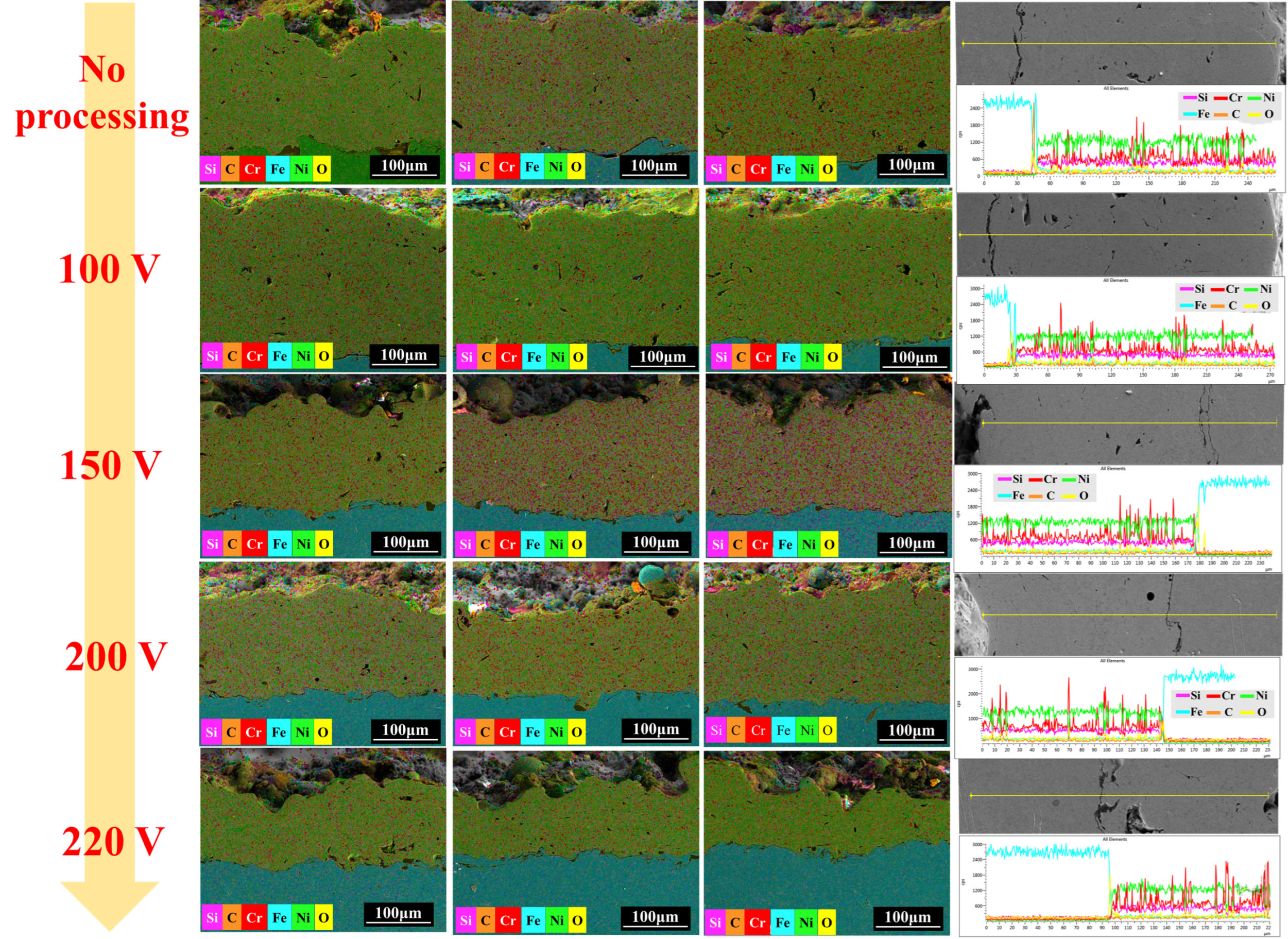
3.1.1. Analysis of Sectional Structure and Dimensional Characteristics of Coating

Based on the results of the scanning electron microscope test, the cross-sectional microstructure of the coatings under different conditions was analysed. The cross-sectional microstructure of the coatings under no magnetic field and under AC magnetic fields of 100 V, 150 V, 200 V, and 220 V was measured at the same magnification. The morphology results are shown in Figure 2. It can be seen from the figure that the cross-sectional quality of the No Processing sample is relatively poor, with many pores and uneven distribution, some of which are concentrated inside the unmelted particles. These pores are caused by the original defects of the powder. However, if the melting and bonding quality of the powder during the spraying process improves, there will be no obvious internal pores in the powder. At the same time, obvious cracks were also observed at the interface, which is related to the incomplete spreading behaviour of the droplets. The droplets cannot fully wet the microstructure of the substrate surface. Thus, it can be discovered that the action of the AC magnetic field can improve the spreading quality. However, at this point, the 100 V AC magnetic field, due to its relatively low intensity, does not have as obvious an effect on the molten coating as the AC magnetic field at higher voltages.
The results of the 150 V sample are shown in the SEM image corresponding to 150 V in Figure 2. The pores have significantly decreased, but their sizes are still large. The formation of these pores is consistent with that of the 100 V sample, both caused by poor spreading quality of the single droplet lamellar structure. The 200 V sample has a larger number of pores, but their sizes are smaller. This phenomenon is related to the increasing intensity of the AC magnetic field, which leads to a more obvious electromagnetic stirring effect inside the coating. During the spraying process of the molten coating, the AC magnetic field continuously changes the direction of the magnetic field, generating a constantly changing Lorentz force inside the metal droplets. This causes the small voids existing inside (one type is captured by the droplet during spreading and has not yet escaped, and the other type is the pores existing inside the powder due to reactions) to continuously detach from their original positions and float up, eventually escaping from the coating. This makes the coating denser. Finally, there is the 220 V sample with the strongest field strength. It can be clearly seen that the coating thickness of this sample has decreased. Under the same scale, the coating deposition efficiency has declined, and the pore distribution is more random. Some areas show a reduction in pores, but large-scale defects still exist. This seriously affects the quality of the coating. This is due to the excessive AC magnetic field strength, which causes chaos in the internal spreading and stacking process during the formation of coating particles. Some droplets are affected by the electromagnetic stirring effect too obviously, reaching the extent of capturing surrounding pores, thereby increasing the porosity of the coating.
The bonding state at the interface can also be seen from Figure 2. Due to the mechanical bonding between the coating and the substrate during the supersonic plasma spraying process, delamination often occurs at the interface. The interface mainly relies on mechanical interlocking to increase the bonding strength of the coating. This is an inherent defect of supersonic plasma spraying. Currently, only the post-treatment of coating remelting can make the coating and the substrate form a metallurgical bond, forming a coating with no interface delamination at all. From Figure 2, all samples have different degrees of interface delamination. The gaps at the interfaces of the samples without magnetic field and at 100 V and 150 V are significantly wider than those at 200 V and 220 V. However, the delamination at the interfaces of 200 V and 220 V is relatively good, and the delamination is far better than the average level of supersonic plasma spraying coatings. But at the interface of 220 V, pores are clearly present. Since there are no moist or gas-releasing substances in the spraying material, it further proves that the pores are caused by the excessive AC magnetic field intensity, which leads to excessive disorder during particle spreading and entraps the surrounding gas.
Subsequently, this paper further analysed the elemental distribution of the cross-section of the coating. The results are shown in Figure 3. The cross-sectional elemental distribution and the overall quality of the coating were analysed by area scanning and line scanning tests for the five coatings. As can be seen from Figure 3, the coating part is mainly green Ni element, the substrate is mainly blue Fe element, and the red Cr element strengthening phase is distributed in the coating. A detailed observation of Figure 3 shows that the red Cr element strengthening phase in the No Processing sample is unevenly distributed, with obvious blank areas not covered by the strengthening phase. However, for the coatings after magnetic field strengthening, such as the 150 V and 200 V samples, the uneven distribution of the strengthening phase is rarely found. This phenomenon indicates that the Cr phase strengthening substances at the cross-section of the coating have been thoroughly stirred by the AC magnetic field, causing the internal phase structure to be rearranged and more regular. The Cr phases in the XRD results are ceramic-like phases such as CrB and Cr3Si. These materials have a relatively higher strength than Ni-based metallic materials. After being uniformly distributed within the coating, they can provide support and significantly improve the hardness distribution and friction and wear performance of the coating in the subsequent process.
The line scanning results of No Processing show that the coating thickness is about 230 μm. While for the 100 V, 150 V, 200 V, and 220 V samples, the thicknesses are 240 μm, 175 μm, 145 μm, and 110 μm respectively. As the magnetic field intensity increases, the coating thickness also changes, showing a general downward trend. During the preparation of the coating samples, the orthogonal test method was adopted to determine the optimal parameters of the supersonic plasma spraying process. Meanwhile, all five coatings were prepared under the same supersonic plasma spraying parameters, and the control variable method was used, with the only varying process parameter being the intensity of the AC magnetic field. Therefore, the variation in coating thickness is closely related to the effect of the AC magnetic field. The AC magnetic field continuously performs electromagnetic stirring and oscillation on the coating, expelling the pores inside the coating and making the structure more compact, which in turn leads to a reduction in coating thickness. Additionally, as the field strength increases, it was found that under a 220 V magnetic field, the coating thickness decreased by nearly half. Besides the reduction in coating porosity, it is also related to the interference of the AC magnetic field on some of the sprayed particles, causing some particles to fail to deposit and spread on the coating. This results in a continuous decrease in coating thickness as the field strength increases. This also indicates that the magnetic field strength of the AC magnetic field device is not positively correlated with the coating quality. Excessively high magnetic field strength can significantly affect the coating quality. In addition to porosity and internal formation quality, other mechanical properties inside the coating will also change accordingly.
The coating thickness statistics are shown in Table 2. The coating thicknesses under no magnetic field and 100 V AC magnetic field are similar. The coating thicknesses gradually decrease under 150 V, 200 V and 220 V AC magnetic fields. This is mainly because the Joule heat generated between the AC magnetic field and the particles makes the particle spreading better, and the electromagnetic stirring and electromagnetic oscillation make the coating more compact. The coating thickness under 220 V AC magnetic field drops particularly much, which may also be due to the excessive magnetic field intensity, causing the particles to receive chaotic Lorentz forces during flight and resulting in a divergent flight trajectory. This leads to a decrease in the coating deposition rate.

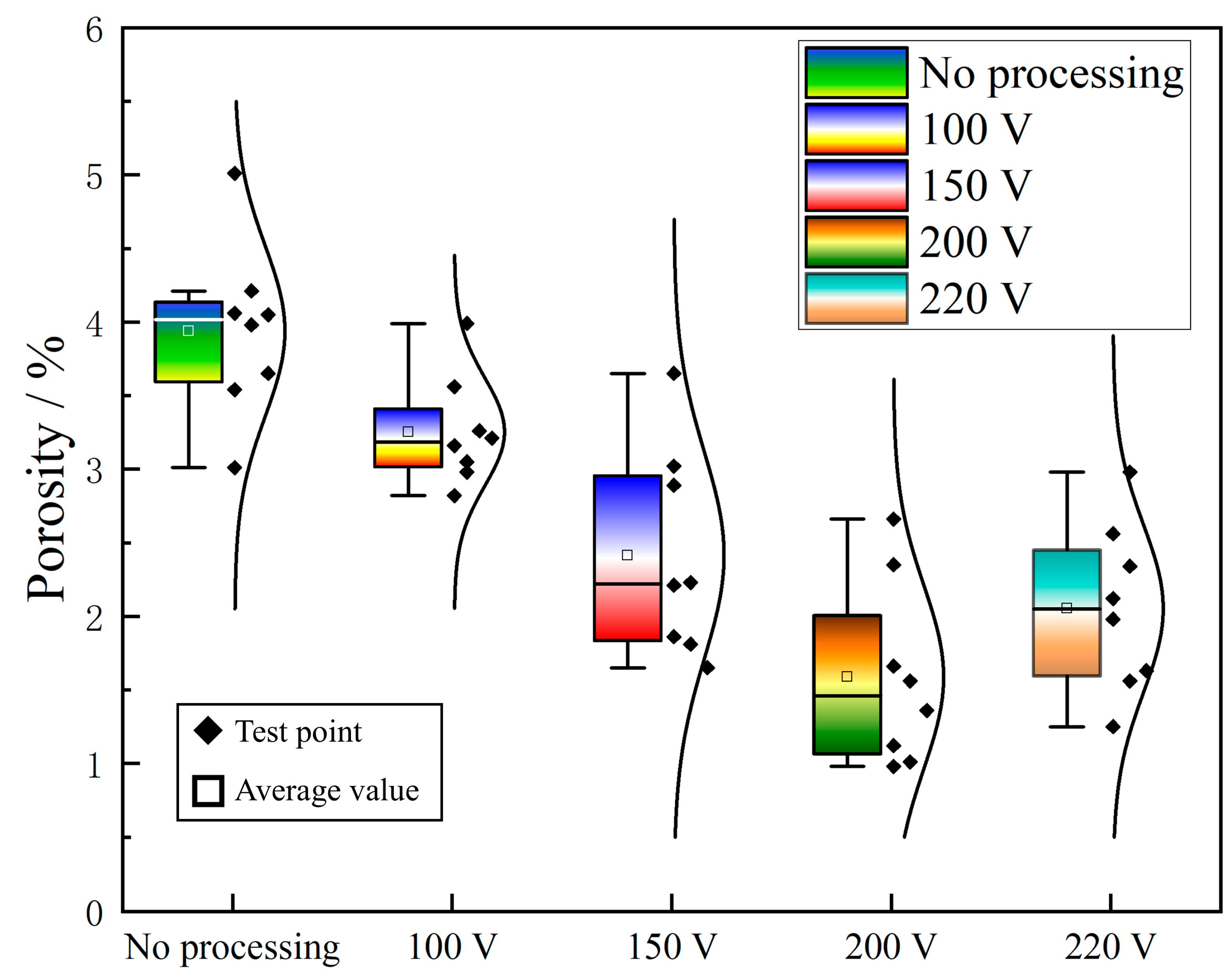
3.1.2. Analysis of Coating Porosity Results

This paper statistically analyses the porosity results of five different gradient coatings. From the results in Section 3.1.1, it can be found that as the magnetic field intensity increases, the internal defects of the coating continuously decrease. However, the coating thickness also decreases, and at 220 V magnetic field, the thickness has already reached half of that without a magnetic field. This will also affect the porosity statistics, so many sample data calculations must be conducted for each type of coating. Targeted porosity results were calculated in 8 photos, and finally, the porosity statistics results graph as shown in Figure 4 was formed.
It can be seen from the figure that as the intensity of the AC magnetic field increases, the porosity inside the coating is constantly decreasing. The mean porosity values from No Processing to 220 V are 3.93%, 3.25%, 2.41%, 1.58%, and 2.05% respectively. The porosity of the samples does not continuously decrease with the increase of the magnetic field intensity. At 220 V, there is no obvious improvement effect. At the same time, from Figure 4, it can also be seen that the dispersion of the 150 V sample is relatively large. This indicates that there is a deviation in its internal quality. However, the overall mean is still in a downward trend. The mean porosity values of the 200 V and 220 V samples are the better results among the samples. However, the dispersion of the 220 V sample is greater, and the error bars are longer. Comparing the results in Figure 2 can also clearly illustrate this point. There is a phenomenon of pore concentration in some SEM samples. However, most of them are in a dense structure. Based on the porosity statistics results, it can be further confirmed that the AC magnetic field within an appropriate range can effectively improve the internal quality of the coating, especially for the control of the coating porosity. However, excessive magnetic field intensity will also affect the internal quality, especially in the thickness of the coating and the problem of pore concentration, which will cause greater harm.

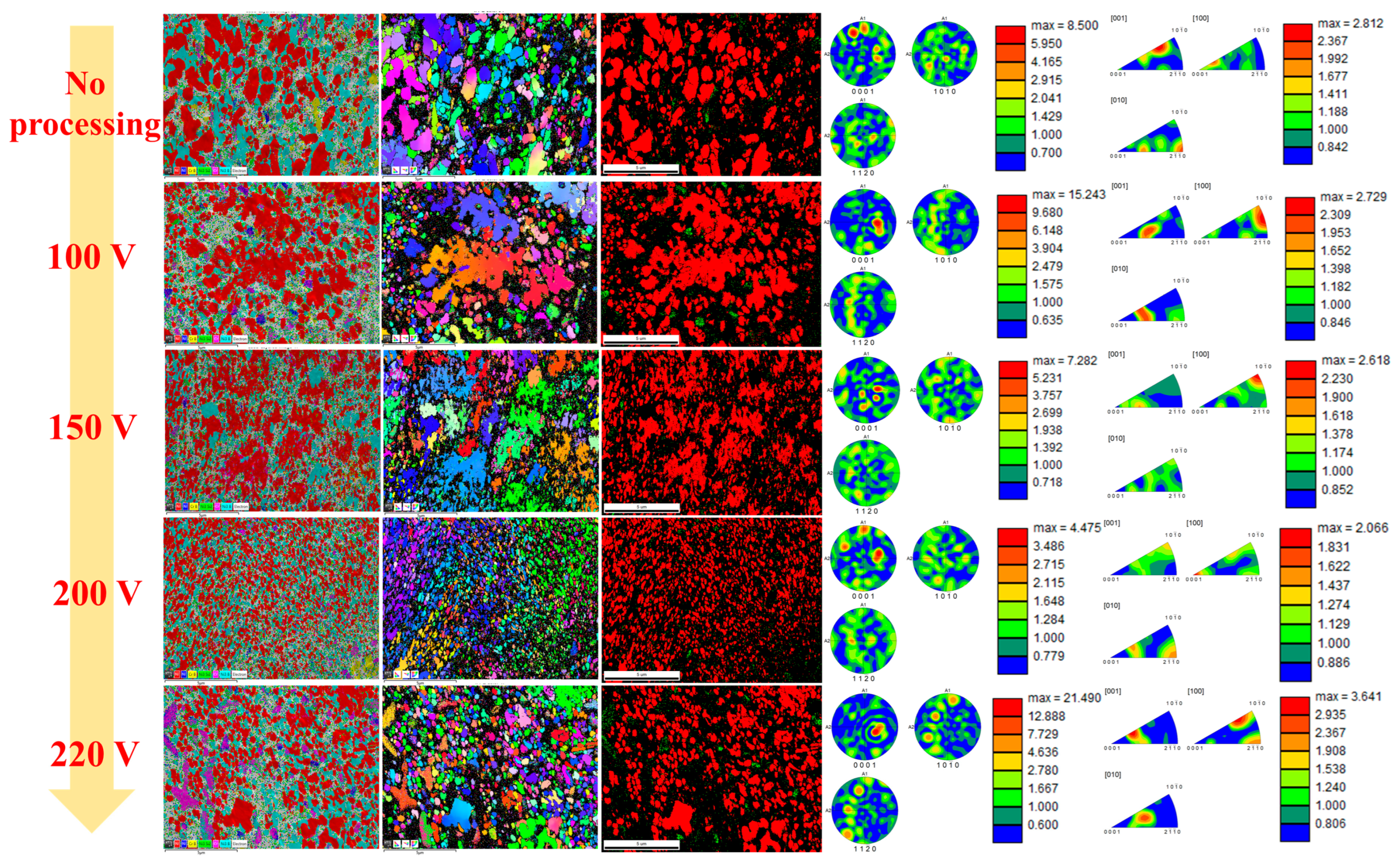
3.1.3. Analysis of Coating Crystallographic Parameters

The AC magnetic field has a quite distinct improvement effect on the crystallographic information of the coating. We analysed the distribution of crystal phase structures, sizes and orientation information of the five types of samples. The results are presented in Figure 5.
It can be seen from the EBSD result graph that the crystal size is constantly decreasing with the increase of the magnetic field. Especially when the magnetic field intensity is 200 V, the crystal shows an obvious refinement phenomenon, forming a typical fine grain strengthening feature. At the same time, the Ni phase structure was selected for analysis and it was also found that the crystal structure was refined. However, the refinement was not as obvious at 220 V as at 200 V. This further indicates that the AC magnetic field has a significant improvement effect on the coating preparation process. The mechanism of action is as follows: (1) The AC magnetic field generates induced eddy currents and Lorentz forces during the solidification of the coating droplets, causing intense flow of the coating droplets. This breaks the segregation of the melt composition, promotes the uniform distribution of nucleation points, and inhibits grain coarsening. (2) The electromagnetic stirring effect can also cause the dendrites formed during the coating melt shaping process to be pulled by the shear force, thereby forming more fine nuclei and significantly increasing the number of grains. (3) The AC magnetic field accelerates the heat dissipation of the melt coating, increases the local undercooling, and increases the nucleation rate. (4) The electromagnetic oscillation effect caused by the AC magnetic field hinders the migration and diffusion of atoms, restricting the further growth of grains. Through the above action mechanisms, the grains inside the coating gradually refine, but the refinement effect does not further improve at 220 V. This is because the AC magnetic field intensity is too large currently, causing the coating melt to oscillate too violently, affecting the spreading of the molten coating. It makes it more in contact with the outside world, introducing impurities, and thereby suppressing the grain refinement phenomenon. Subsequently, we analysed the texture orientation of the coating. The texture orientation of the coating without a magnetic field is on the [010] crystal plane and the (2 11 ¯ 0) crystal direction. At 100 V, it is on the [100] crystal plane and between the (10 1 ¯ 0) and (2 11 ¯ 0) crystal directions. The 150 V sample is at the [100] crystal plane and the (10 1 ¯ 0) position. At 200 V and 220 V, multiple texture orientation positions appear. After the coating is subjected to the AC magnetic field during the preparation process, the crystal refinement effect is produced first, and then the orientation of most of the crystals also changes accordingly. At the same time, the AC magnetic field also promotes the alignment of grains along the easy magnetization axis according to the ferromagnetic characteristics of Ni-based materials, and the crystal structure orientation is deflected accordingly. When most of the crystal structures are deflected in one direction, a crystal texture is produced. The existence of texture makes the coating behave more regularly when subjected to stress. Especially when the texture orientation of the crystal is parallel to the stress direction, the crystals all face the stress direction and can resist more stress loads, which significantly improves the service performance of the coating.

3.2. Analysis of Mechanical Properties of Coating

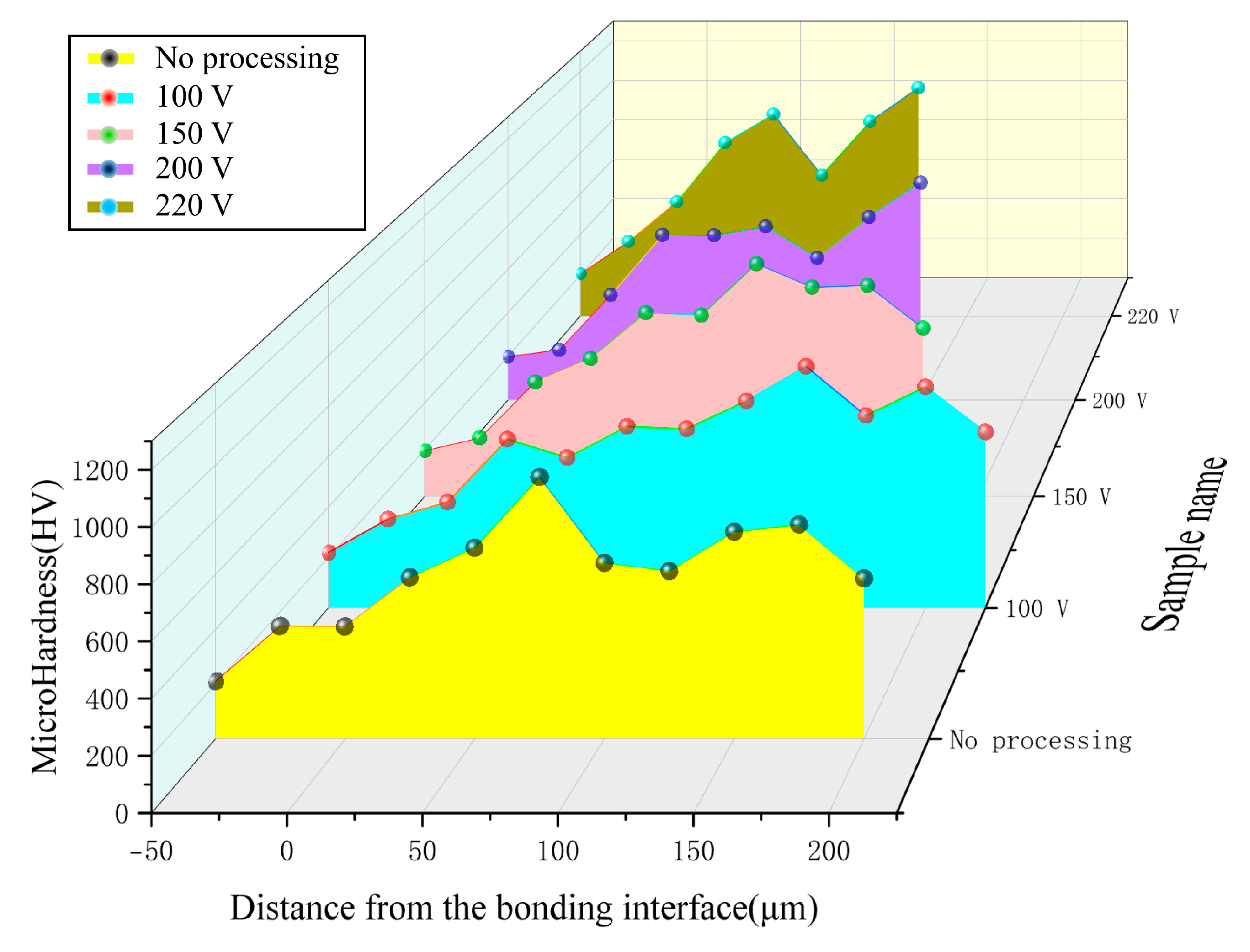
3.2.1. Analysis of Hardness Test Results of the Coating

The hardness of Ni-based composite coatings is a crucial indicator reflecting the service performance of the coatings themselves. Particularly for the surfaces of rotating structural components such as bearings during actual service, the hardness values of the surface and subsurface are significant indicators for evaluating the service quality of the components. Commonly, a hard and wear-resistant coating is fabricated on the surfaces of large structural components such as crankshafts through supersonic plasma spraying. Figure 6 presents the hardness distribution results of five gradient coatings. To better analyse the hardness of the coating on the component, the hardness distribution results measured in this paper extend from the substrate to the interface and up to the coating surface, thereby reflecting the actual state of the surface and subsurface of the component coating. It can be discerned from the results that there is no distinct hardness disparity at the substrate and interface of the five coatings, suggesting that the metallurgical bonding effect of the coating at the interface is not prominent. This portion merely reflects the hardness of the substrate. Subsequently, as it extends to the coating, the hardness value gradually varies. Due to the inconsistent coating thickness, the average value is analysed. The average hardness values of the five coatings from No Processing to 220 V are 702.88, 752.27, 809.04, 800.35, and 921.12 HV, respectively. It can be observed from the hardness results that the hardness escalates with the increase in the magnetic field intensity. Nevertheless, the hardness values of the 150 V and 200 V samples are nearly identical. The hardness value of the 220 V sample increases significantly. Simultaneously, it can be noted from Figure 6 that the 220 V sample has obvious peaks and troughs, indicating that the randomness of the hardness value is relatively substantial. This is associated with the thinner coating and random defect distribution of the 220 V sample. Additionally, by comparing the hardness results of the surface and subsurface of the coating, it is discovered that the hardness of the 200 V and 220 V samples exhibits the same trend, with relatively lower hardness in the subsurface. During the friction and wear process, the peak contact stress frequently occurs slightly beneath the surface. If the hardness value at this position is higher, it will demonstrate lower plasticity and higher brittleness. Whereas a softer surface will be the opposite. This structure of a soft outer layer and a hard core can withstand more friction loads, significantly reducing the defects and cracks caused by the surface, and thereby enhancing the tribological performance of the coating. However, it is found from the figure that the 200 V and 220 V samples do not exhibit this characteristic in the subsurface; conversely, the No processing, 100 V, and 150 V samples display this phenomenon. This will result in the 200 V and 220 V samples being more prone to tribological damage at the initial stage of the subsequent tribological service. Nevertheless, the overall hardness value of the coating portion of the 200 V and 220 V samples is higher, and their long-term wear service performance is still superior to other samples. Furthermore, it is once again determined that the hardness of the magnetic field is not positively correlated with the magnetic field intensity during the coating preparation process, and its optimal control range is approximately 900 Gs at 200 V.

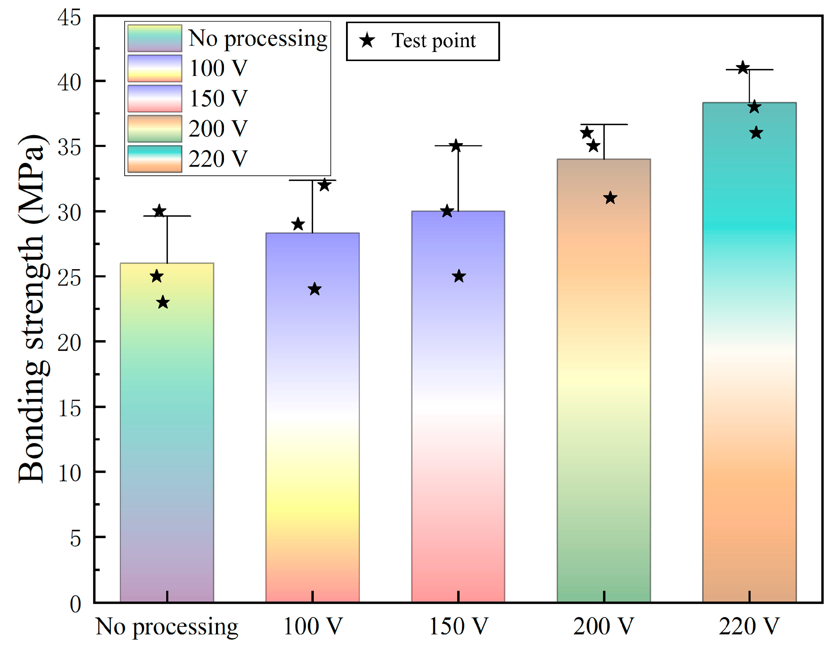
3.2.2. Analysis of Test Results of Bonding Strength of Coating

The bonding strength of the coating is also a crucial indicator reflecting the quality of the coating. The supersonic plasma spraying technology mainly yields mechanical bonding, thus the bonding strength is predominantly associated with the interface structure and the wetting state between the droplets. Meanwhile, the AC magnetic field will prominently influence the wetting behaviour of the coating via electromagnetic stirring, thereby affecting the bonding strength of the coating. Figure 7 shows the statistical results of the bonding strength of five types of coatings. To ensure the authenticity of the data, each coating sample was tested three times, and the corresponding results are marked with star symbols in Figure 7.
It can be observed from Figure 7 that with the increase in the intensity of the AC magnetic field, the bonding strength of the coating undergoes a marked enhancement. This is closely associated with the electromagnetic effect generated by the AC magnetic field. The AC magnetic field has a distinct electromagnetic stirring and oscillation effect on the molten coating. Electromagnetic stirring can optimize the pores and defects present within the molten coating, particularly exerting a significant optimizing effect on the pores that are difficult to escape. It also serves to evenly distribute the defects, preventing their concentration and adverse impact on the bonding performance. Electromagnetic oscillation can directly act on the pores through oscillation, accelerating their escape. Once the pores and defects have been significantly ameliorated, the lamellar structure within the coating will be combined more tightly, forming superior mechanical and metallurgical bonding characteristics, and ultimately improving the bonding strength of the coating. It is worth noting that since the powder employed in the experiment is Ni-based metal powder, it exhibits ferromagnetic properties below the Curie temperature. It will also be further attracted by the AC magnetic field, augmenting the contact area between the interfaces and further enhancing the bonding strength of the coating. This constitutes the primary reason why the bonding strength of the coating does not exhibit a significant downward trend at 220 V. The improvement effect on the bonding strength continues to increase as the intensity of the AC magnetic field rises. This differs from the results of hardness and porosity. It indicates that the AC magnetic field has a highly pronounced improvement effect on the bonding strength of the coating and does not lead to performance deterioration due to an excessively high field strength. This is related to the fact that the bonding strength reflects the internal structure of the coating and the bonding state between the coating structure and the substrate interface. Ferromagnetic powder will be continuously drawn to form more mechanical interlocking states at the interface, thereby continuously elevating the bonding strength.

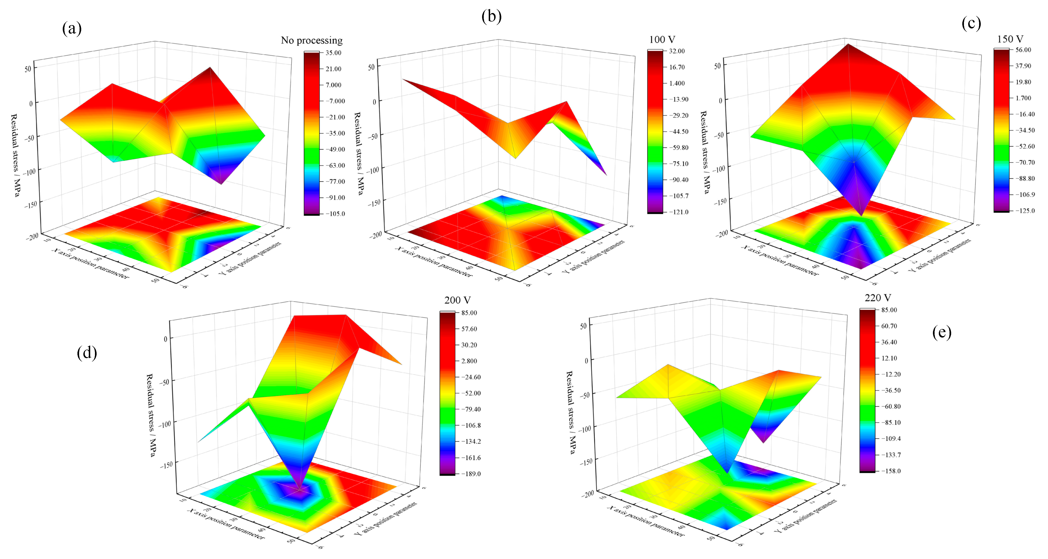
3.2.3. Analysis of Residual Stress Test Results of Coating

The distribution of residual stress in the coating exerts a significant influence on the surface structure quality of the coating itself, the interfacial bonding state, and the ultimate tribological service performance. It is also a crucial factor causing surface warping and cracking of the coating. Hence, in this paper, the residual stress values at multiple points on the coating surface were measured, and the residual stress distribution results as depicted in Figure 8 were summarized.
It can be discerned from Figure 8a–e that the upper and lower graduations of the ordinate are within the same range. With the increase of the magnetic field, the distribution of residual stress shifts downward overall. Particularly during the 150 V, 200 V, and 220 V processes, the decline is more pronounced. The average values of residual stress for the five types of coatings, ranging from No Processing to 220 V, are −31.4, −35.5, −33.3, −43.7, and −47.3 MPa respectively. A marked decrease can be perceived in the average values of residual stress. From the distribution trends in Figure 8, we can also observe that the surfaces of the 150 V, 200 V, and 220 V coatings (as depicted in Figure 8c–e) are almost entirely in a state of residual compressive stress. Residual stress in the coating fabrication process mainly comprises thermal stress, phase transformation stress, and deposition process stress. Among them, thermal stress is related to the thermal expansion coefficients between the coating and the substrate. The coating fabrication is a rapid quenching process, often resulting in a significant amount of residual tensile stress due to thermal stress. Phase transformation stress is mainly associated with the phase transformation of the coating material during the cooling process. For the Ni-based metal coating in this article, the majority undergoes contraction phase transformation, and the main residual stress generated is also tensile stress. Deposition process stress is mainly induced by the bombardment of high-energy particles on the metal surface. The characteristics of high temperature and high velocity applied to the particles in supersonic plasma spraying generate a considerable amount of residual stress. The above three aspects all exert a regulatory role on the residual stress of the coating. The AC magnetic field applied in this paper can enhance the undercooling degree and crystal structure of the coating through various electromagnetic effects such as electromagnetic stirring and electric field oscillation, thereby controlling the growth of residual tensile stress and achieving the control of the internal stress of the coating. This leads to the continuous increase of the residual stress of the coating with the increase of the AC magnetic field. During the service of the coating, instantaneous scratch wear, short-term reciprocating wear, and long-term fatigue wear are all related to residual stress. Particularly, the presence of residual compressive stress has an excellent improvement effect on the service performance of the coating. Residual compressive stress can inhibit the initiation and propagation of surface microcracks and enhance the surface load-bearing capacity, making the coating surface more resistant to wear. Conversely, residual tensile stress will significantly promote crack propagation in the coating and even cause the failure phenomenon of coating spalling. Simultaneously, residual tensile stress will also weaken the bonding force between the coating and the substrate, increasing the risk of coating warping and deformation. Therefore, the AC magnetic field can induce more residual compressive stress within the coating by controlling thermal stress and phase transformation stress, thereby exerting a favourable role in improving the wear resistance performance of the coating surface.

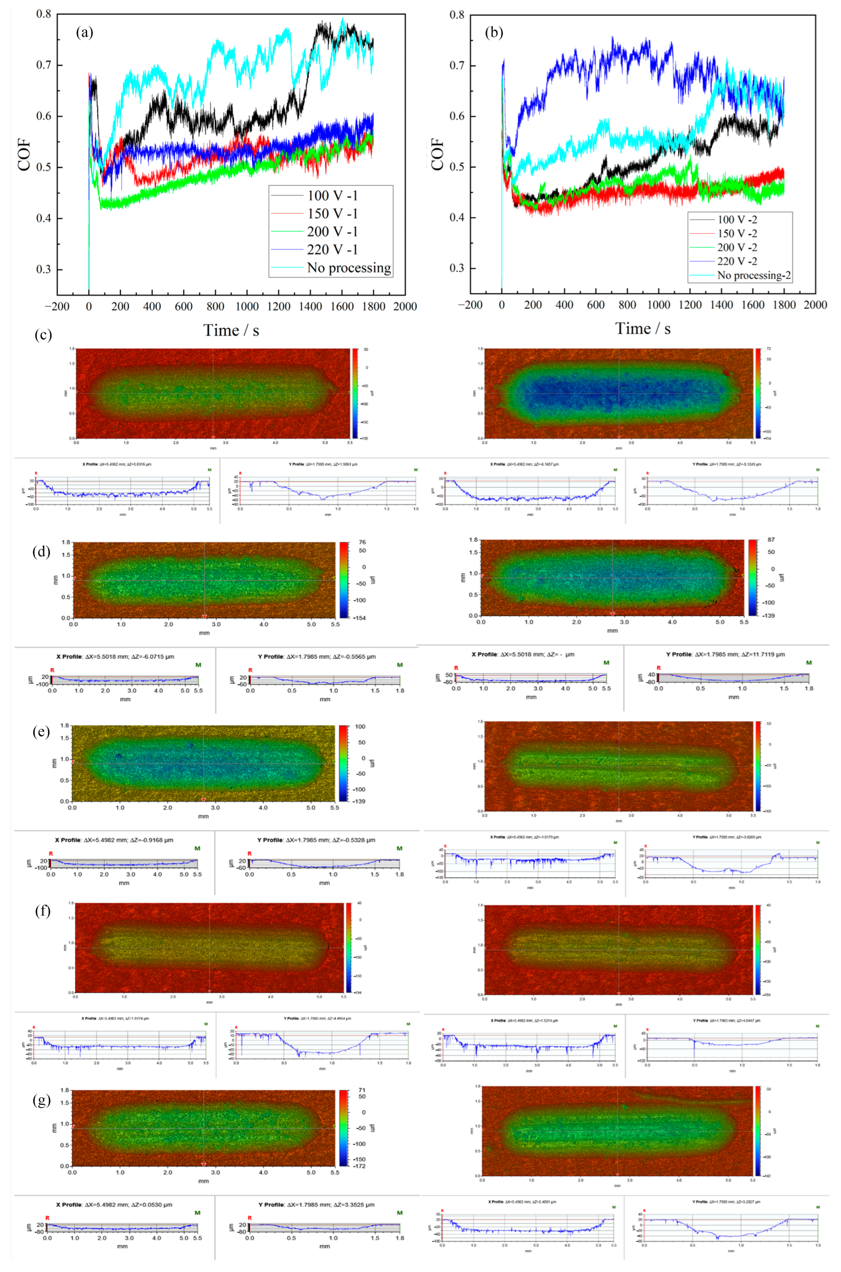
3.3. Analysis of Tribological Properties of Coatings

Figure 9 depicts the test results of the tribological properties of five types of coatings. Among them, Figure 9a and Figure 9b respectively represent the two sets of tribological curve test outcomes of the five types of coatings. Figure 9c, Figure 9d, Figure 9e, Figure 9f, Figure 9g respectively correspond to the three-dimensional morphology results of wear from No processing to 220 V samples.
It can be observed from Figure 9a that the tribological curve of the No processing sample is almost consistently at a relatively high level. Subsequently, there are the 100 V, 150 V and 200 V samples, while the tribological curve of the 220 V sample is close to that of the 150 V sample, but neither performs as well as the 200 V sample. However, from Figure 9b, a different outcome emerges. The No processing sample exhibits poor performance. The 150 V sample yields the best result among these samples, while the 220 V sample has the poorest performance, even worse than the No processing sample. Figure 9c–g show the white light wear morphologies of five groups of samples. From the wear morphologies, the edges of the wear marks of the samples without magnetic field and at 150 V and 220 V have obvious damages. This is related to the bonding strength and density of the coating. The edge of the wear mark at 200 V is neat, without any breakage or large-scale damage, indicating that there is more internal residual compressive stress and higher bonding strength. Through the three-dimensional morphology, the wear volume can be further calculated. For more precise analysis, we conducted statistics on the parameters and formed the results as shown in Table 3:
It can also be discerned from Table 1 that the statistical outcomes are analogous to those in Figure 9. By contrasting the average tribological curve values and the computed wear volume results, it can be discovered that the results of 150 V and 200 V among the five coatings are relatively superior. The optimal performance is manifested in the 150 V-2 sample. Nevertheless, the overall service performance of 200 V is more favourable. The 220 V sample does not exhibit excellent tribological performance, but it is still somewhat better than the samples without magnetic field treatment. Tribological performance is a crucial indicator reflecting the ultimate quality of the coating. It directly reveals various defect issues within the coating, particularly the pore distribution, phase structure, hardness, and residual stress within the coating. The key properties of the coating were tested in the foregoing section. It was discovered that upon treatment with a 200 V AC magnetic field, the porosity of the coating decreased from 3.93% to 1.58%. The phase structure was conspicuously refined, and the hardness escalated from 702.88 to 921.12 HV. The bonding strength ascended from 26 MPa to 38.3 MPa. Based on the outcomes of the tribological performance, it can be concluded that the AC magnetic field exerts an overall ameliorating effect on the coating, with the optimal process occurring at 200 V. At this juncture, the AC magnetic field, via electromagnetic effects, causes the coating droplets to exhibit superior melting quality. During the spreading process, they have more contact with the substrate interface. Simultaneously, the electromagnetic stirring and oscillation effects of the AC magnetic field will further eliminate the pores and defects within the coating, enabling the lamellar structure within the coating and the bonding between the lamellar structure and the substrate surface to be more favourable, thereby enhancing the bonding strength of the coating and rendering its structure more compact. Concurrently, a considerable amount of residual compressive stress is introduced.
These factors all have a pronounced improvement effect on the tribological performance [26]: (1) The coating is more compact internally, which will diminish the fluctuation of the friction coefficient attributed to the presence of pores during the friction process, thereby enhancing the anti-wear performance of the coating [26]. (2) The reduction of internal defects in the coating will also curtail the occurrence of micro-cracks and large-scale pitting and spalling during service [27]. (3) The improvement of the coating bonding quality will render the coating less susceptible to obvious delamination and spalling [28]. (4) The existence of residual compressive stress can inhibit the initiation and propagation of surface cracks and augment the surface load-bearing capacity [29]. The combined influence of these factors optimizes the tribological performance.

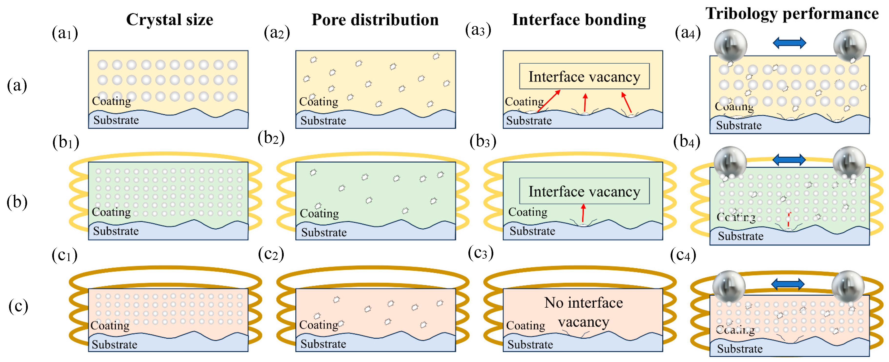
3.4. The Forming Mechanism and Tribological Behaviour of Coating Were Discussed with the Aid of High Strength Energy Field

In this section, based on the analysis results of the microstructure, mechanical properties and tribological properties of the coating presented earlier, the formation mechanism of the coating with the assistance of the AC magnetic field and its influence on the tribological properties are summarized. The summary diagram of the mechanism is shown in Figure 10.
To better delineate the effect of the AC magnetic field, we selected three representative coating formation mechanisms for elaboration. Figure 10a depicts the coating formation mechanism at No processing, Figure 10b represents the coating formation mechanism at 200 V, and Figure 10c illustrates the coating formation mechanism at 220 V.
First, by comparing Figure 10(a1–c1), it can be seen that the crystal size inside the coating becomes increasingly finer under the action of the AC magnetic field. This corresponds to the EBSD results in Figure 4. The main mechanism is related to the electromagnetic stirring and electromagnetic oscillation effects caused by the AC magnetic field during the spraying process. Among them, electromagnetic stirring accelerates the flow inside the melt, breaks the dendrites in the melt, and increases the rate and efficiency of crystal nucleation and grain refinement. At the same time, electromagnetic stirring also helps to suppress the composition segregation in the melt and improve other comprehensive mechanical properties inside the coating. The AC magnetic field also utilizes electromagnetic stirring to generate forced convection. The main basis is Faraday’s law of electromagnetic induction. When the magnetic flux through a certain cross-section change, it drives the directional movement of charged particles. Charged particles move in a circular motion under the centripetal Lorentz force in the magnetic field. Therefore, a certain speed of circular forced flow is generated inside the melt, and a directional induced current is produced in the melt. The forced convection effect can break the primary dendrites, and the dendrite fragments enter the melt and re-nucleate, which is conducive to the formation of equiaxed crystals and grain refinement. At the same time, it can also promote heat transfer, reduce the temperature gradient inside the coating, increase the local undercooling, and increase the nucleation rate, which further reduces the grain size. The electromagnetic oscillation effect caused by the AC magnetic field also further hinders the migration and diffusion of atoms, limits the grain growth, and avoids defects such as cracks caused by coarse primary grains. The combined strengthening of the two effects can also promote rapid crystal nucleation. In addition, since the supersonic plasma spray coating belongs to a rapid cooling process, many nanoscale crystals are formed. The effect of the AC magnetic field is continuously amplified, ultimately resulting in grain refinement. However, in Figure 10(c1), the 220 V sample has a too high AC magnetic field intensity, and the coating powder particles are constantly disturbed during flight. This leads to a significant decrease in the coating deposition efficiency and thickness. This result also corresponds to Figure 2 and Figure 3. The crystal size inside the coating does not show a more refined state due to the change in the particle flight and spreading behaviour. The refinement of the crystal structure has the most obvious impact on improving the strength and hardness of the coating. The higher the coating hardness, the less likely it is to be damaged by frictional loads, thereby improving the tribological properties of the coating.
Figure 10(a2), Figure 10(b2) and Figure 10(c2) respectively show the pore distribution of the coating under the influence of the AC magnetic field. This result corresponds to Figure 2 and Figure 5. Under the action of the AC magnetic field, the coating powder particles undergo obvious electromagnetic stirring and flow. This causes the internal residual pores to continuously escape, thereby reducing the internal pores of the coating and improving the coating’s density. However, in Figure 10(c2), it is found that the 220 V sample has a thinner coating. Some pores are not controlled and discharged by the AC magnetic field, resulting in no obvious decrease in the pore result. The reduction of internal pores in the coating will increase the overall density, making it smoother during wear and avoiding fluctuations in the friction coefficient caused by local defects.
Figure 10(a3), Figure 10(b3) and Figure 10(c3) respectively show the interface bonding conditions of the coating. This result corresponds to the bonding strength results in Figure 6. Due to the better spreading quality of the particles under the action of the AC magnetic field, the particles at the interface can better wet the substrate interface. More interlocking structures are formed at the coating interface, increasing the bonding strength of the coating. At the same time, due to the reduction of pores in Figure 10b, the inclusions are more evenly distributed under the electromagnetic stirring effect, reducing the occurrence of pores and inclusions at the interface. Pores and inclusions can form local cracks in the subsequent spraying process, seriously affecting the interface bonding quality and even causing cracking at the interface and inside the coating. The internal bonding quality of the coating and its bonding strength with the substrate are significantly improved due to the AC magnetic field. This performance will further reduce the delamination and spalling phenomena generated during the wear process, thereby improving the tribological performance of the coating. Figure 10(a4,b4,c4) summarize the service mechanism of the tribological performance of the coating. Tribological performance is the core indicator reflecting the overall service quality of the coating. It has a clear correlation with the surface quality, internal structure and overall stress state of the coating. The AC magnetic field improves the hardness, porosity and bonding strength of the coating by improving the internal crystal structure, pore content and interface spreading quality of the coating. These parameters are all key indicators for evaluating the tribological performance of the coating. The combined effect of the three aspects has greatly improved the tribological performance of the coating.

4. Conclusions

In this paper, an AC magnetic field auxiliary device was employed to fabricate Ni-based composite coatings under the control of a gradient magnetic field via supersonic plasma spraying. The formation and subsequent tribological service behaviours of the coatings under AC magnetic fields ranging from 0 to 220 V were explored, and the following conclusions were drawn:
(1) The gradient AC magnetic field brought about significant changes in the porosity distribution, phase structure, hardness, bonding strength, and residual stress of the coatings. Through the comparison between the coatings treated without a magnetic field and those under the optimal magnetic field conditions, it was discovered that after AC magnetic field reinforcement, the porosity of the coatings decreased from 3.93% to 1.58%, the phase structure was notably refined, the hardness rose from 702.88 to 921.12 HV, the bonding strength increased from 26 MPa to 38.3 MPa, and the residual compressive stress significantly augmented. These enhancements in the fundamental microstructure and mechanical properties collectively improved the tribological performance of the coatings, with the tribological coefficient dropping from 0.6859 to 0.4670.
(2) The AC magnetic field enhanced the internal quality of the coatings by influencing the flight and spreading of the coating powder particles. From the SEM results, it was clearly observed that the enhanced spreading ability of the particles led to a reduction in cross-sectional porosity and a decrease in interface defects. This was associated with the electromagnetic stirring and forced convection effects of the AC magnetic field. By substituting manual stirring, the compactness of the coatings was continuously enhanced, and internal defects were mitigated. These improvement measures not only impacted the porosity and bonding strength but also facilitated particle nucleation acceleration, grain refinement, hardness increase, and an increase in the residual compressive stress within the coatings. Ultimately, they directly influenced various microstructures and mechanical properties of the coatings.
(3) The AC magnetic field also exerted a marked improvement on the tribological behaviour of the coatings. The improvements in hardness and bonding strength enabled the coatings to withstand more intense frictional load impacts. The reduction in porosity contributed to a decrease in tribological service fluctuations, and the increase in residual compressive stress hindered the occurrence of cracking and warping in the coatings. These combined effects effectively enhanced the tribological service performance of the coatings.
(4) The magnetic field strength of the AC magnetic field was not positively correlated with the service quality of the coatings. Particularly when the magnetic field strength was excessively high, it would lead to a reduction in coating thickness. This was attributed to the fact that the coating powder particles, after being disturbed by the AC magnetic field, were unable to fully spread on the substrate. This phenomenon concurrently affected the porosity and hardness of the coatings and deteriorated their tribological performance.

Author Contributions

Conceptualization, Q.Y., Z.W. and Y.J.; methodology, Q.Y., Y.D. and X.Z.; formal analysis, J.X. and Y.D.; Data curation, Z.W. and F.B.; writing—original draft, J.X. and X.Z.; writing—review & editing: Y.D., J.L. and Y.J.; supervision, F.B. and J.L. All authors have read and agreed to the published version of the manuscript.

Funding

The paper was financially supported by the General program of the Heilongjiang Natural Science Foundation Outstanding youth project (Grant Nos. YQ2022E010 and YQ2024E040) and the National Funded Postdoctoral Researchers Program (Grant. No. GZC20230637).

Institutional Review Board Statement

Not applicable.

Informed Consent Statement

Not applicable.

Data Availability Statement

The data presented in this study are available on request from the corresponding author (wangzhiyuan@hrbust.edu.cn).

Acknowledgments

The authors gratefully acknowledge the Army Armored Force Academy and Harbin Institute of Technology for their equipment support and theoretical guidance.

Conflicts of Interest

Authors Qingwen Yun, Jun Xiong, Ying Dong, Xi Zhu, Jinyu Li and Yunan Jin were employed by the company Avic Harbin Aircraft Industry Group Co., Ltd. The remaining authors declare that the research was conducted in the absence of any commercial or financial relationships that could be construed as a potential conflict of interest.

References

  1. Li, X.; Liu, H.; Guo, W.; Zhou, L.; Cui, Q.; Deng, X.; Shu, W.; Shi, T.; Xing, Z.; Wang, H. Effect of TiO2 content on the thermal control properties of Al2O3-xTiO2 composite coatings prepared by supersonic plasma spraying technology. J. Mater. Res. Technol. 2024, 32, 3582–3593. [Google Scholar] [CrossRef]
  2. Kalluri, S.; Yoon, M.; Jo, M.; Liu, H.K.; Dou, S.X.; Cho, J.; Guo, Z. Feasibility of cathode surface coating technology for high-energy lithium-ion and beyond-lithium-ion batteries. Adv. Mater. 2017, 29, 1605807. [Google Scholar] [CrossRef] [PubMed]
  3. Yang, M.; Liang, Y.; Huang, T.; Jin, Q.; Kong, D.; Song, P. Oxidation behaviour properties of carbide ceramic reinforced Ni-based composite coatings at 700 °C. Ceram. Int. 2024, 50, 37504–37517. [Google Scholar] [CrossRef]
  4. Zhou, L.; Ma, G.; Wang, H.-D.; Wang, W.; Mou, H.; Zhu, X.; Zhao, H.; Li, Y.; Tan, N. High-aspeed laser cladded Ni-based cermet coating with high ceramic phase content derived from core-shell structured powder. Surf. Coat. Technol. 2024, 489, 131110. [Google Scholar] [CrossRef]
  5. Miyamoto, N. Automotive Coatings and Applications. In Thermal Spray Technology; ASM International: Almere, The Netherlands, 2013; pp. 298–305. [Google Scholar]
  6. Michalak, M.; Latka, L.; Sokolowski, P.; Toma, F.-L.; Myalska, H.; Denoirjean, A.; Ageorges, H. Microstructural, mechanical and tribological properties of finely grained Al2O3 coatings obtained by SPS and S-HVOF methods. Surf. Coat. Technol. 2020, 404, 126463. [Google Scholar] [CrossRef]
  7. Nowakowska, M.; Łatka, L.; Sokołowski, P.; Szala, M.; Toma, F.-L.; Walczak, M. Investigation into microstructure mechanical properties effects on sliding wear cavitation erosion of Al2O3–TiO2 coatings sprayed by, A.P.S.; SPS; S-HVOF. Wear 2022, 508, 204462. [Google Scholar] [CrossRef]
  8. Kovářík, O.; Haušild, P.; Siegl, J.; Chráska, T.; Matějíček, J.; Pala, Z.; Boulos, M. The influence of substrate temperature on properties of APS and VPS W coatings. Surf. Coat. Technol. 2015, 268, 7–14. [Google Scholar] [CrossRef]
  9. Alidokht, S.A.; Wu, L.; Bessette, S.; Chromik, R.R. Microstructure and tribology of cold spray additively manufactured multimodal Ni-WC metal matrix composites. Wear 2024, 538, 205218. [Google Scholar] [CrossRef]
  10. XZhang, C.; Xu, B.S.; Tu, S.T.; Xuan, F.Z.; Wang, H.D.; Wu, Y.X. Effect of spraying power on the microstructure and mechanical properties of supersonic plasma-sprayed Ni-based alloy coatings. Appl. Surf. Sci. 2008, 254, 6318–6326. [Google Scholar] [CrossRef]
  11. Han, D.; Pan, Y.; Niu, Y.; Chen, Y.; Qi, Z.; Pan, X.; Zheng, X.; Chen, G. Isothermal oxidation resistance microstructure evolution of VPS-TiAlCrY coating on TiAl single crystals at 1100–1200 °C. Corros. Sci. 2022, 208, 110664. [Google Scholar] [CrossRef]
  12. Song, J.; He, D.; Guo, W.; Huang, Y.; Li, Z.; Wang, H.; Xing, Z. Effect of magnetic field type on the flight state of supersonic plasma spray particles and coating properties. J. Therm. Spray Technol. 2023, 32, 1637–1651. [Google Scholar] [CrossRef]
  13. Wang, Z.; Huang, Y.; Zhou, J.; Zhang, L.; Xing, Z.; Wang, H.; Shan, D. Effect of Fe content on the tribological properties of Ni60 coatings applied by pulsed magnetic field assisted supersonic plasma spraying. Mater. Charact. 2022, 185, 111771. [Google Scholar] [CrossRef]
  14. Zhou, J.; Guo, W.; He, D.; Huang, Y.; Cai, Z.; Zhou, L.; Xing, Z.; Wang, H. Study on preparation and wear resistance of NiCrBSi-WC/Co composite coatings by pulsed magnetic field assisted supersonic plasma spraying. Surf. Coat. Technol. 2022, 448, 128897. [Google Scholar] [CrossRef]
  15. Zhang, L.; Huang, Y.; He, D.; Guo, W.; Li, G.; Dong, T. Effect of Steady Magnetic Field on Microstructure and Effect and Properties of NiCrBSi Coating by Supersonic Plasma Properties Plasma Spraying. Rare Met. Mater. Eng. 2023, 52, 103–110. [Google Scholar]
  16. Wang, J.; Fautrelle, Y.; Nguyen-Thi, H.; Reinhart, G.; Liao, H.; Li, X.; Zhong, Y. Thermoelectric magnetohydrodynamic flows and their induced change of solid–liquid interface shape in static magnetic field-assisted directional solidification. Metall. Mater. Trans. A 2016, 47, 1169–1179. [Google Scholar] [CrossRef]
  17. Long, Z.; Wang, J.; Fautrelle, Y.; Li, X. Repeated nucleation behaviors of pure bismuth under a high magnetic field. J. Alloys Compd. 2020, 831, 154746. [Google Scholar] [CrossRef]
  18. Bu, F.; Xue, X.; Wang, J.; Kou, H.; Li, C.; Zhang, P.; Beaugnon, E.; Li, J. Effect of strong static magnetic field on the microstructure and transformation temperature of Co–Ni–Al ferromagnetic shape memory alloy. J. Mater. Sci. Mater. Electron. 2018, 29, 19491–19498. [Google Scholar] [CrossRef]
  19. Wu, M.; Liu, T.; Dong, M.; Sun, J.; Dong, S.; Wang, Q. Directional solidification of Al–8wt.% Fe alloy under high magnetic field gradient. J. Appl. Phys. 2017, 121, 064901. [Google Scholar] [CrossRef]
  20. Hou, M.; Li, K.; Li, X.; Zhang, X.; Rui, S.; Wu, Y.; Cai, Z. Effects of pulsed magnetic fields of different intensities on dislocation density, residual stress, and hardness of Cr4Mo4V steel. Crystals 2020, 10, 115. [Google Scholar] [CrossRef]
  21. Qian, C.; Li, K.; Rui, S.-S.; Hou, M.; Zhang, X.; Wu, Y.; Cai, Z. Magnetic induced re-dissolution and microstructure modifications on mechanical properties of Cr4Mo4V steel subjected to pulsed magnetic treatment. J. Alloys Compd. 2021, 881, 160471. [Google Scholar] [CrossRef]
  22. Zhu, Y.; Zhou, H.; Chen, Z.; Wang, Z.; He, F.; Xu, C. Study on Microstructure and Properties of Ni60A/WC Composite Coating by Alternating-Magnetic-Field-Assisted Laser Cladding. Micromachines 2022, 13, 653. [Google Scholar] [CrossRef] [PubMed]
  23. Duan, W.; Bao, J.; Liu, W.; Zhang, Z.; Cui, J. Simulation on DC casting of magnesium alloy under out-of-phase pulsed magnetic field with different coil connection strategies. Int. J. Heat Mass Transf. 2020, 162, 120353. [Google Scholar] [CrossRef]
  24. Zhang, X.; Zhang, Y. Experimental study on enhanced heat transfer and flow performance of magnetic nanofluids under alternating magnetic field. Int. J. Therm. Sci. 2021, 164, 106897. [Google Scholar] [CrossRef]
  25. Wang, Z.; Huang, Y.; Guo, W.; He, D.; Wang, H.; Shan, D.; Xing, Z. Development of pulsed magnetic field assisted supersonic plasma spraying. Rev. Sci. Instrum. 2022, 93, 123901. [Google Scholar] [CrossRef]
  26. Munagala VN, V.; Bessette, S.; Gauvin, R.; Chromik, R.R. Sliding wear of cold sprayed Ti6Al4V coatings: Effect of porosity and normal load. Wear 2020, 450, 203268. [Google Scholar] [CrossRef]
  27. Vereschaka, A.A.; Grigoriev, S.N. Study of cracking mechanisms in multi-layered composite nano-structured coatings. Wear 2017, 378, 43–57. [Google Scholar] [CrossRef]
  28. Jiang, C.-P.; Xing, Y.-Z.; Zhang, F.-Y.; Hao, J.-M.; Song, X.-D. Wear resistance and bond strength of plasma sprayed Fe/Mo amorphous coatings. J. Iron Steel Res. Int. 2014, 21, 969–974. [Google Scholar] [CrossRef]
  29. Lu, M.; Wang, H.; Song, X.; Sun, F. Effect of doping level on residual stress, coating-substrate adhesion and wear resistance of boron-doped diamond coated tools. J. Manuf. Process. 2023, 88, 145–156. [Google Scholar] [CrossRef]
Figure 1. The device of supersonic plasma spraying assisted by AC magnetic field (a) Structural diagram of the device (b) The XRD test results of the coating powder (cf) Test diagrams of the AC magnetic field intensity distribution.
Coatings 15 00496 g001
Figure 2. SEM images of coating cross section morphology under different magnetic field intensities.
Coatings 15 00496 g002
Figure 3. EDS diagram of coating cross section morphology under different magnetic field intensities.
Coatings 15 00496 g003
Figure 4. Distribution of coating porosity under different magnetic field intensities.
Coatings 15 00496 g004
Figure 5. EBSD diagram of coating under different magnetic field intensity.
Coatings 15 00496 g005
Figure 6. Distribution of coating hardness under different magnetic field intensities.
Coatings 15 00496 g006
Figure 7. Distribution of coating bonding strength under different magnetic fields.
Coatings 15 00496 g007
Figure 8. Residual stress distribution of coating under different magnetic field intensities (a) No processing (b) 100 V (c) 150 V (d) 200 V (e) 220 V.
Coatings 15 00496 g008
Figure 9. Wear performance results of coatings under different magnetic field intensities (a) COF results of the first group of coatings (b) COF results of the second group of coatings (c) No processing coating wear morphology (d) 100 V coating wear morphology (e) 150 V coating wear morphology (f) 200 V coating wear morphology (g) 220 V coating wear morphology.
Coatings 15 00496 g009
Figure 10. Influence of magnetic field on coating construction mechanism and tribological service mechanism: (a) No processing (b) 200V (c) 220V.
Coatings 15 00496 g010
Table 1. Experimental parameters.
AC Magnetic Field ParametersSpraying Parameters
voltage100 V/150 V/200 V/220 Vspraying voltage120 V
spraying current430 A
peak field strength426/694/920/1015 GsH2 Flow18 L/min
Ar Flow120 L/min
form of actionContinuous inputSpraying times10
spraying distance125 mm
Table 2. Coating thickness statistical.
Group 1Group 2Group 3
No processing190 μm215197
100 V229202220
150 V180181182
200 V166121164
220 V130119117
Table 3. Statistical table of tribological properties of five coatings.
Average COF-1Average COF-2The Wear Volume-1
(×10−3 mm−3)
The Wear Volume-2
(×10−3 mm−3)
No processing0.68590.57850.13860.1344
1 Tesla0.62400.51130.13120.1239
3 Tesla0.52050.45180.12560.1202
5 Tesla0.49310.46700.12120.1195
7 Tesla0.53850.67680.12670.1335
Disclaimer/Publisher’s Note: The statements, opinions and data contained in all publications are solely those of the individual author(s) and contributor(s) and not of MDPI and/or the editor(s). MDPI and/or the editor(s) disclaim responsibility for any injury to people or property resulting from any ideas, methods, instructions or products referred to in the content.

